Article

Formation Kinetics of the Mixed Cyclopentane—Carbon Dioxide Hydrates in Aqueous Sodium Chloride Solutions

1
Guangzhou Institute of Energy Conversion, Chinese Academy of Sciences, Guangzhou 510640, China
2
CAS Key Laboratory of Gas Hydrate, Guangzhou 510640, China
3
Guangdong Provincial Key Laboratory of New and Renewable Energy Research and Development, Guangzhou 510640, China
4
Guangzhou Center for Gas Hydrate Research, Chinese Academy of Sciences, Guangzhou 510640, China
*
Author to whom correspondence should be addressed.
Energies 2020, 13(17), 4388; https://doi.org/10.3390/en13174388
Submission received: 15 July 2020 / Revised: 15 August 2020 / Accepted: 20 August 2020 / Published: 26 August 2020

Abstract

:
Hydrate formation from cyclopentane (CP) and carbon dioxide was measured at 281 K by powder X-ray diffraction (PXRD) and macroscopic methods. The effect of initial pressure and CP mass fraction in liquid phase was analyzed. The results showed that hydrate formation was assumed to start with the nucleation of the mixed CP-CO2 hydrate with small fraction of CO2 followed by a large continuous CO2 adsorption. Initial pressure was found to have a positive correlation with the total CO2 consumptions when the initial pressure was below 2.5 MPa. However, the total CO2 consumptions dropped by over a half as the initial pressure was 3.0 MPa. PXRD revealed that all the hydrate samples formed at different initial pressures were structure II. The CO2 consumptions were assumed to be inhibited by the competitive occupation of 51264 cages between CP and CO2 molecules when the initial pressure was above 2.5 MPa. The CO2 consumptions were also found to be reduced as the CP mass fraction was above 0.25. An excess of CP molecules was not assumed to strengthen the formation of the mixed CP-CO2 hydrates at the initial stage, but increased the thickness of liquid CP film at aqueous brine and hydrate particles, which increased the diffusion resistance of CO2 molecules. Therefore, the suitable initial pressure and the CP mass fraction for the mixed CP-CO2 hydrate formation should be around 2.5 MPa and 0.2, respectively.

Graphical Abstract

1. Introduction

Gas hydrates are stoichiometric solid compounds comprised of water and guest molecules where water molecules constitute a cage-like host lattice through hydrogen bonding, and gas molecules such as methane (CH4) and carbon dioxide (CO2) are trapped in the hydrate cages as guest molecules [1]. Now, growing attention has been paid to gas hydrate because of its huge reserves in nature. A conservative estimation shows that the amount of carbon stored in natural gas hydrates is twice that of all other carbon sources combined [2,3]. Motivated by the mining of natural gas hydrates, gas hydrates have seen a huge push in research and show great potential in some other fields, such as carbon capture, energy storage, refrigerant and desalination [4,5,6,7,8].
The idea of obtaining pure water from seawater by hydrate crystallization provides an alternative for desalination. Compared to thermal distillation, the energy consumption required for hydrate formation is only 4.84 kJ/mol, which is much lower than the heat (40.7 kJ/mol) required for water vaporization [9]. The running conditions of hydrate-based desalination are also higher than those of freezing desalination which is usually carried out below ice point. In addition, the crystallization method has obvious effects on the removal of toxic metal ions, which can be used in pre-desalination systems [10].
At present, the research on hydrate-based desalination technology focuses on moderating the hydrate forming temperature and pressure as well as improving the salt removal efficiency. In view of thermodynamics, large guest molecules such as cyclopentane (CP) and CO2 are reported to greatly moderate the hydrate forming conditions. CO2 hydrate belongs to sI hydrate that comprises six 51262 and two 512 hydrate cages per unit cell and the equilibrium temperature is 1.45 MPa at 273.2 K [11,12]. CP molecules are too large to be trapped in the 51262 cages and form sII hydrate which consists of eight 51264 and sixteen 512 cages per unit cell. Below 283 K, CP hydrate can even be stably preserved at atmospheric pressure [13]. To further increase the hydrate forming temperature, Herslund et al. [14] found that the equilibrium pressure of the mixed CP-CO2 hydrates at 291.6 K is only 2.58 MPa. The mixed CP-CO2 hydrates belonged to structure II hydrate where CP molecules were only encaged in the 51264 cages [15]. In addition, they were found to have higher salt removal efficiency than CP hydrates alone [12,16]. However, the effect of salt removal caused by hydrate growth led to an increase in salt concentration, which was not conducive to the subsequent hydrate growth. Zha et al. [17] noted that the equilibrium pressure of CO2 hydrate increased from 3.2 to 3.8 MPa as the salt concentration increased from 10 to 20 wt%, and the inhibition effect on hydrate growth would be higher with the increasing valence of anions.
To enhance the salt removal efficiency, a series of methods have been proposed, such as reducing the induction time of hydrate nucleation, and increasing the hydrate growth rates and solid–liquid separation efficiency. Takeya et al. [18] proposed to form hydrates using the water produced by the dissociation of ice or hydrates which may greatly reduce the induction time of hydrate formation. Temperature oscillation was also found to have a positive effect on the reduction in the induction time [19]. In hydrate growth stage, He et al. [20] proposed to increase the stirring rate to enhance the hydrate formation rate. To strengthen the heat transfer during hydrate growth, Kang et al. [21] placed a stainless-steel brush in a hydrate reactor in order to remove the hydrate layer attached to the wall. To enhance the solid–liquid separation efficiency, Park et al. [22] used a squeezing operation of a dual cylinder unit to pelletize the hydrates in hydrate slurry. The removal efficiency of different kinds of ions ranged from 72 to 80%. Han et al. [23] used washing, centrifuging and sweating to treat the formed hydrates and the removal efficiency reached 93, 95 and 96 wt% respectively. Liu et al. [24] used a twin reactor to purify the sea water in multi-stage and found that the salt removal increased with the increase in desalination stage. After four stages of desalination, the salt concentration was lower than the standard of drinking water.
Although CP-CO2 mixed hydrates demonstrate well performance in hydrate-based desalination, the kinetic properties of CP-CO2 mixed hydrates in the presence salts have not been fully revealed. To strengthen the formation kinetics of CP-CO2 mixed hydrates, the influence of initial pressure in the range of 1.5 to 3.0 MPa and CP mass fraction in a range of 0.10 to 0.30 was analyzed. The structure of the formed hydrates was also examined by powder X-ray diffraction (PXRD) to check the potential structural change. Finally, the suitable initial pressure and CP mass fraction for hydrate formation were obtained which was suggested to be beneficial to the research of hydrate-based desalination technology.

2. Experimental Section

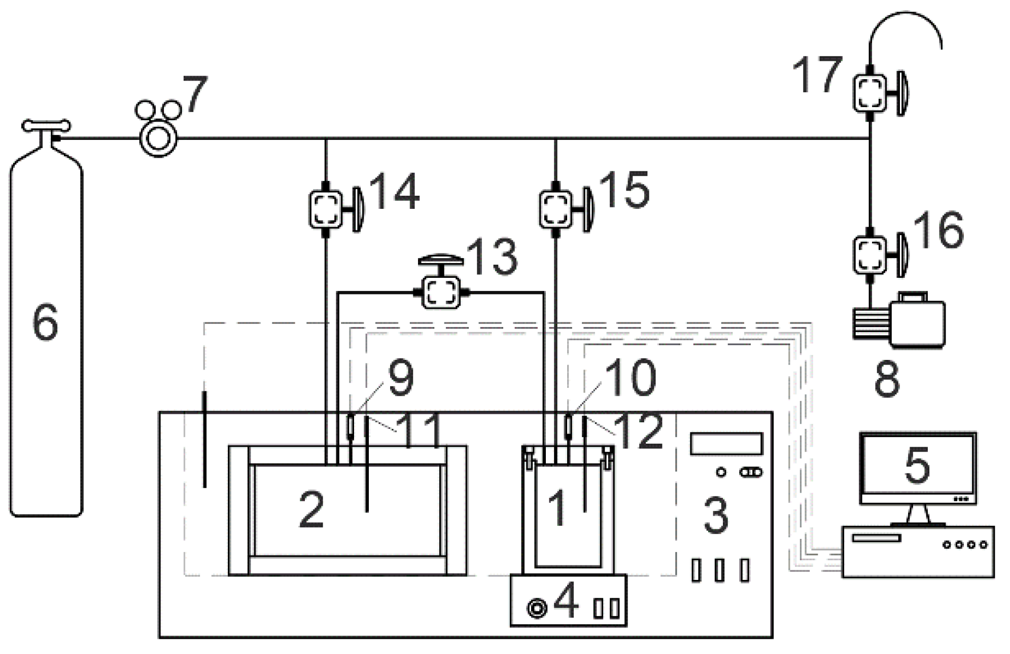
2.1. Materials and Apparatus

To synthesize the CP-CO2 mixed hydrates, research grade CO2 (99.9 mol% in purity, Foshan Gas Co., Ltd., Foshan, Guangdong, China) and CP (99 wt% in purity, Sigma-Aldrich, Shanghai, China) were used as guest molecules, and deionized water (18.0 ± 0.2 mΩ∙cm−1) which is made in the laboratory was used to form the host lattice of hydrates. Sodium chloride with a purity of 99.5 wt% was also supplied by Sigma-Aldrich. All the materials were used without further purification.
The apparatus used for hydrate formation included a high-pressure reactor and a buffer tank with an internal volume of 98 and 516 mL respectively as seen in Figure 1. They were made of stainless steel and connected by a high-pressure needle valve. A magnetic stirrer was equipped in the high-pressure reactor to agitate the liquid content. The temperature and the pressure of the high-pressure reactor and the buffer tank were measured by platinum resistance thermometers (PT100) and pressure transducers, with an uncertainty of ±0.1 K and ±0.015 MPa, respectively. The inner temperature of the high-pressure reactor and buffer tank was controlled by a thermostatic bath with a temperature control range of 263 to 323 K.
The structure of the hydrate samples was measured by a powder X-ray diffraction spectrometer (PANalytical, X’Pert Pro MPD) using Cu Kα radiation (40 kV, 40 mA). The samples were scanned at a scanning rate of 2°/min from 2θ = 5 to 80° with a step of 0.017°. The samples were paved on a stage chilled at 173 K by liquid nitrogen so that the hydrate samples were thought to remain stable during scanning.

2.2. Procedure

The high-pressure reactor was first washed by deionized water three times and dried. Thirty milliliters of prepared liquid consisting of brine (3.5 wt% NaCl) and cyclopentane were loaded into the high-pressure reactor in sequence and evacuated. Then, the buffer tank, which contained about 4 MPa gaseous CO2, and the reactor were connected and cooled in a thermostatic bath. When the temperature reached stability at 281 K, the CO2 in the buffer tank was slowly injected into the reactor to the set value within 1 min. After that, the stirrer was turned on at 300 rpm which was defined as the start of the hydrate formation. The pressure and temperature of the reactor was recorded. In the hydrate formation, no additional CO2 was injected into the reactor and it usually took over 4 days for the hydrate forming system to reach the end, where the fluctuation of the pressure and temperature in the reactor did not surpass 0.02 MPa and 0.1 K within 5 h. In this work, over 70% of the pressure drop caused by hydrate formation took place in the initial 800 min and the remaining 30% was suggested to be controlled by the gas diffusion in the hydrate phase. Therefore, the kinetic performance of hydrate formation in the initial 800 min was compared and discussed, while the total CO2 consumptions were calculated using the pressure and temperature recorded at the start and the end of hydrate formation.
The hydrate samples for PXRD measurements were taken from the macroscopic experiments. After hydrate formation, the reactor was taken from the thermostatic bath and immersed in liquid nitrogen. As the temperature in the reactor reached around 263 K, the reactor was depressurized and opened quickly. Then the reactor was filled with liquid nitrogen to prevent hydrate dissociation and precipitation of water vapor on hydrate surface. Finally, the hydrate samples were finely ground and preserved in liquid nitrogen.

3. Results and Discussion

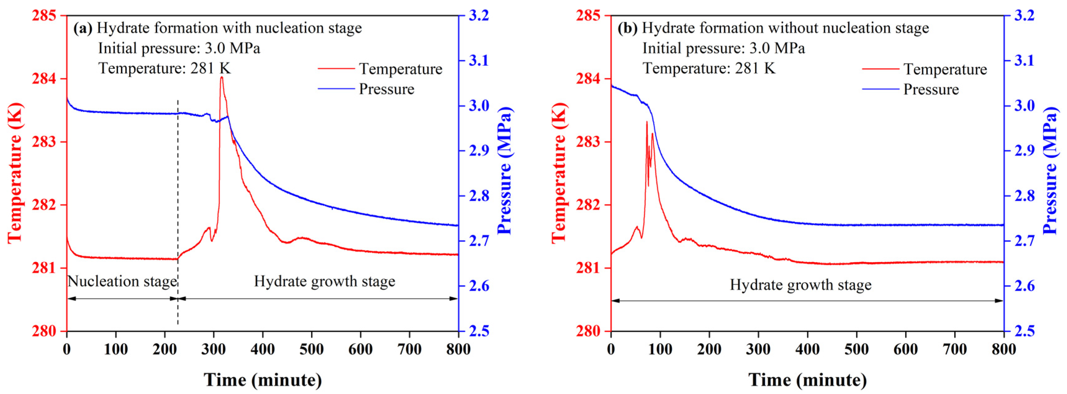
3.1. Kinetic Features

A typical CO2 hydrate formation can be regarded as a crystallization process that starts with a nucleation stage followed by hydrate growth stage [20]. The nucleation stage is the period between the creation of the supersaturate solution and the occurrence of the first crystals of gas hydrates. In the presence of CP, the hydrate crystallization process could be divided into two categories: the hydrate formation with or without a nucleation stage. In the hydrate formation with a nucleation stage, the pressure went through two evident drops accompanied with a sharp rise in temperature respectively. The first pressure drop corresponded to the dissolution of the CO2 molecules into liquid CP and aqueous brine, and the release of the dissolution heat [25,26]. However, CP molecules were immiscible with brine and formed CP hydrate at 281 K, atmospheric pressure [27]. The crystallization of CP hydrates did not take place once they came into contact. In the second pressure drop, CO2 and CP molecules were thought to form the mixed CP-CO2 hydrates simultaneously until a stable state was reached [28]. The heat release from hydrate growth led to the second temperature jump, as seen in Figure 2a. As the hydrate growth proceeded, the number of free water molecules for hydrate formation got fewer, which reduced the growth rate of hydrates so that the temperature rise reduced gradually.
However, the formation of the mixed CP-CO2 hydrates at the initial stage of hydrate growth was a little different from that of typical CO2 hydrate. A gradual increase in temperature was found to occur with no evident pressure decrease at the initial stage of hydrate growth, then a sharp temperature jump was observed, accompanied by an evident decrease in pressure. The gradual temperature increase was suggested to be induced by the heat release of hydrate formation. Since the equilibrium pressure of pure CO2 hydrate in 3.5 wt% NaCl solution was over 3.5 MPa and CP hydrate could form without CO2 at 281 K, the hydrates formed in the initial stage of hydrate growth should be the mixed CP-CO2 hydrates which contained only a small fraction of CO2 molecules [29,30,31,32].
In the hydrate formation without a nucleation stage, the pressure dropped continuously through the hydrate formation. The mixed CP-CO2 hydrates were thought to crystallize once the hydrate formation started. However, the gradual increase in temperature was also found in the initial stage of hydrate growth, indicating that the mixed CP-CO2 hydrates with a small fraction of CO2 tended to form first in the formation of the mixed CP-CO2 hydrates regardless of the presence of nucleation stage [33]. Judging from the pressure decrease during the hydrate growth stage, time consumed for CO2 adsorption was the same for the hydrate formation with or without nucleation stage. In this case, the hydrate formation without a nucleation stage reduced the nucleation time, which was more efficient. In order to standardize the hydrate formation process, the hydrate formation without nucleation stage was used.

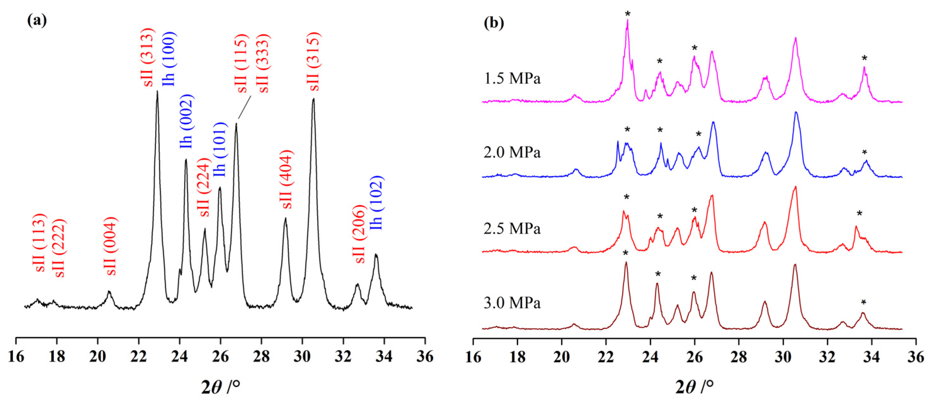
3.2. Effect of Initial Pressure

The effect of initial pressure on the mixed CP-CO2 hydrate formation was measured by setting the CP mass fraction at 0.2 since the CP mass fraction in ideal CP hydrates was 0.186. In Figure 3a, all the pressure profiles were found to start with a slow decrease at the initial stage and followed by a large pressure drop. Interestingly, the time required for the initial stage of hydrate growth lengthened as the initial pressure increased from 1.5 to 3.0 MPa. Theoretically, higher initial pressure corresponded to faster CO2 diffusion and the time required for the initial stage of hydrate growth was shorter as the initial pressure increased. It was likely to be caused by the competitive occupation of 51264 cages between CP and CO2 molecules. With the increasing pressure, more CO2 molecules tended to occupy the 51264 cages, leading to the decrease in stability of sII hydrate. The subsequent growth of the mixed CP-CO2 hydrate was suggested to limited by the adsorption of CP molecules. Therefore, higher pressure was suggested to inhibit the CP hydrate formation at the initial stage. Another phenomenon is that the pressure was found to reach stability within 400 min when the initial pressure was above 2.0 MPa. However, the pressure kept decreasing for over 800 min at the initial pressure of 1.5 MPa. This was assumed to be caused by the low driving force for CO2 penetration in hydrate phase. Therefore, high initial pressure allowed CO2 molecules to be consumed within fewer minutes, although it may prolong the initial stage of hydrate growth.
The total CO2 consumptions were not found to have a positive correlation with initial pressure. At 800 min, the CO2 consumptions rose from 0.020 to 0.029 moles when the initial pressure increased from 1.5 to 2.5 MPa, but dropped by half and down to only 0.014 moles as the initial pressure reached 3.0 MPa as seen in Figure 3b. This was also consistent with the total CO2 consumptions obtained at the end of each experiment, as seen in Table 1. Combined with the analysis of the prolonged initial stage of hydrate growth, the competitive occupation of 51264 cages between CP and CO2 molecules was suggested to inhibit the growth of the hydrate phase and led to a dramatic drop in total CO2 consumption under high initial pressure. Therefore, the formation of the mixed CP-CO2 hydrate was inhibited when the pressure was over 2.5 MPa.
Although the total CO2 consumption reduced by over half as the initial pressure increased from 2.5 to 3.0 MPa, the structures of the formed hydrates were not found to change. The results from PXRD measurements showed that all the formed hydrates belonged to structure II hydrate. In Figure 4a, the Bragg peaks of sII hydrate and hexagonal ice could be clearly seen and no other types of hydrate structures were observed from the samples. It was reported that pure CO2 hydrate could be sI hydrate or the coexistence of sI and sII hydrates under moderate hydrate forming conditions [34,35]. Since the CP mass fraction used for initial pressure tests was 0.2, which was generally in accord with the CP mass fraction in typical CP hydrate, the amount of CP molecules was enough to guarantee all the free water molecules to the host lattice of sII hydrate. On the other hand, CP molecules were too big to occupy the cages in sI hydrate and the mixed CP-CO2 hydrate was more thermodynamically stable than pure CO2 hydrate [15,34,36]. In the presence of NaCl, the hydrate structures with less stability were easier to be destroyed, and sII hydrate was more suitable for stable hydrate forming system. Therefore, the decrease in total CO2 consumption at the initial pressure of 3.0 MPa was not induced by the structural change during hydrate formation, but the competitive occupation of 51264 cages between CP and CO2 molecules [34,37,38,39].

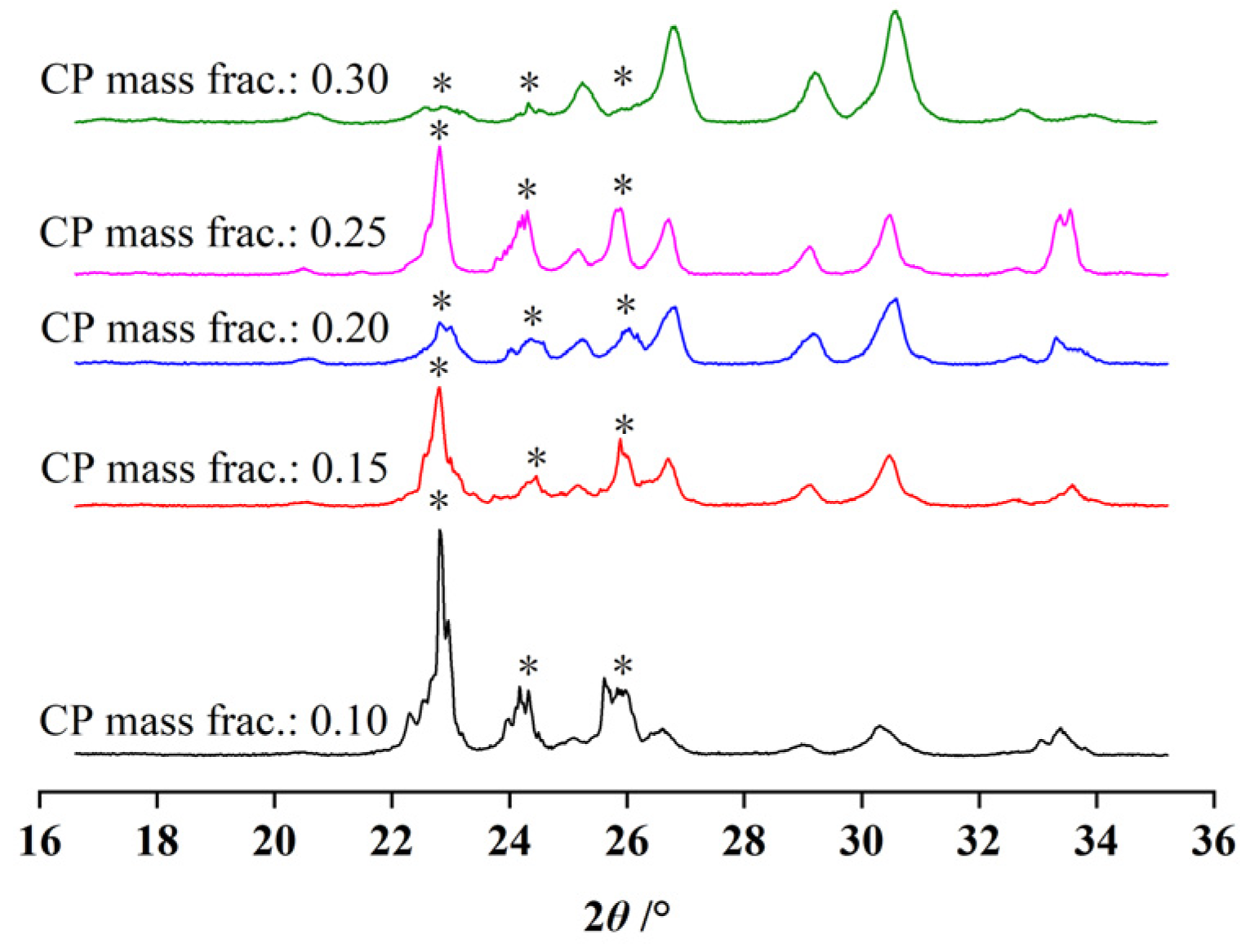
3.3. Effect of the CP Mass Fraction

The effect of CP mass fraction on the mixed CP-CO2 hydrate formation was measured by setting the initial pressure at 3.0 MPa. The pressure drop was found to increase as the CP mass fraction increased from 0.1 to 0.2, as seen in Figure 5a. As the CP mass fraction was above 0.25, the pressure drop reduced significantly and the profiles of pressure were also different. At the initial 400 min, one or two pressure spikes could be seen, which was suggested to be the sudden heat release caused by hydrate formation and gas dissolution. Then, pressure kept decreasing within 800 min, which was different from the experiments where the CP mass fraction was 0.25 and 0.3.
Influenced by the pressure spikes, all the CO2 consumption curves fluctuated at the initial stage of hydrate growth, as seen in Figure 5b. This phenomenon was suggested to be affected by the high initial pressure, which was analyzed above. The CO2 consumptions were also found to be affected by CP mass fraction. The CO2 consumptions increased with an increase in the CP mass fraction from 0.1 to 0.2, but dropped dramatically as the CP mass fraction was 0.25 and 0.3. Since the CP mass fraction in ideal CP hydrates was 0.186, a large amount of excessive free CP molecules would be found in the system as the CP mass fraction reached 0.25 and 0.3 as seen in Table 2. Based on previous analysis, the mixed CP-CO2 hydrate tended to form at the interphase between CP and brine at the initial stage so that excessive CP molecules were not beneficial to the hydrate growth [40,41]. In addition, excessive CP molecules could increase the thickness of liquid CP film on aqueous brine and hydrate particles, which increased the diffusion resistance of CO2 molecules. Therefore, too much CP in the hydrate forming system was not good in enhancing the efficiency of hydrate formation. The highest CO2 consumption occurred when the CP mass fraction was 0.2 which was close to the CP mass fraction in ideal CP hydrates.
PXRD measurements showed that all of the formed hydrates were also structure II. The volume of the formed hydrates grew with an increase in the CP mass fraction. Since the CP mass fraction in ideal CP hydrates was 0.186, excessive amounts of water molecules would be left after the hydrate forming system if the CP mass fraction was below 0.186. Therefore, the Bragg peaks of hexagonal ice were more evident than those of sII hydrates when the CP mass fractions were 0.15 and 0.1, as seen in Figure 6. Theoretically, all of the free water molecules would convert into sII hydrates when the CP mass fraction was above 0.186 since CP hydrate could be formed stably in these thermodynamic conditions without CO2 molecules. In this case, the number of CO2 molecules consumed for hydrate formation could not be used to evaluate the amount of hydrate formed in the system.

4. Conclusions

In this work, the kinetic properties of mixed CP-CO2 hydrate formation were measured at 281 K. PXRD was also used to examine the structure of the formed hydrates. The effect of initial pressure and CP mass fraction in liquid phase was analyzed. The results showed that the formation of the mixed CP-CO2 hydrates was similar to the typical hydrate formation process from the aqueous phase. However, the mixed CP-CO2 hydrate containing a small fraction of CO2 was suggested to form first followed by large continuous CO2 adsorption. The suitable initial pressure and the CP mass fraction for the mixed CP-CO2 hydrate formation was 2.5 MPa and 0.2, respectively. High initial pressure was found to have a positive correlation with the CO2 consumption in crystallization as the initial pressure was below 2.5 MPa. When initial pressure was 3.0 MPa, the total CO2 consumption dropped by more than half. Combined with the results of PXRD, the CO2 adsorption was assumed to be inhibited by competitive occupation of 51264 cages between CP and CO2 molecules. Meanwhile, the CO2 consumption was also found to be inhibited as the CP mass fraction was above 0.25. Excessive CP molecules were not assumed to be beneficial in strengthening the formation of the mixed CP-CO2 hydrates at the initial stage, but in increasing the thickness of liquid CP film at aqueous brine and hydrate particles, which increased the diffusion resistance of CO2 molecules.

Author Contributions

Conceptualization, D.L.; Methodology, X.Z. (Xiaoya Zang); Investigation, Y.Z.; Writing—Review and Editing, X.Z. (Xuebing Zhou). All authors have read and agreed to the published version of the manuscript.

Funding

This research was funded by National Natural Science Foundation of China (51706230), National Key Research and Development Plan of China (2017YFC0307306), Guangdong Natural Science Foundation (2020A1515010374), Guangdong MEPP Fund (No.GDOE [2019]A39).

Conflicts of Interest

The authors declare no conflict of interest. The funders had no role in the design of the study; in the collection, analyses, or interpretation of data; in the writing of the manuscript, or in the decision to publish the results.

References

  1. Sosso, G.C.; Chen, J.; Cox, S.J.; Fitzner, M.; Pedevilla, P.; Zen, A.; Michaelides, A. Crystal Nucleation in Liquids: Open Questions and Future Challenges in Molecular Dynamics Simulations. Chem. Rev. 2016, 116, 7078–7116. [Google Scholar] [CrossRef] [PubMed] [Green Version]
  2. Xu, C.G.; Li, X.S.; Yan, K.F.; Ruan, X.K.; Chen, Z.Y.; Xia, Z.M. Research progress in hydrate-based technologies and processes in China: A review. Chin. J. Chem. Eng. 2019, 27, 1998–2013. [Google Scholar] [CrossRef]
  3. Li, F.G.; Yuan, Q.; Li, T.D.; Li, Z.; Sun, C.Y.; Chen, G.J. A review: Enhanced recovery of natural gas hydrate reservoirs. Chin. J. Chem. Eng. 2019, 27, 2062–2073. [Google Scholar] [CrossRef]
  4. Zhou, X.B.; Liang, D.Q. Enhanced performance on CO2 adsorption and release induced by structural transition that occurred in TBAB∙26H2O hydrates. Chem. Eng. J. 2019, 378, 122128. [Google Scholar] [CrossRef]
  5. Ma, S.H.; Zheng, J.N.; Tian, M.R.; Tang, D.W.; Yang, M.J. NMR quantitative investigation on methane hydrate formation characteristics under different driving forces. Fuel 2020, 261, 116364. [Google Scholar] [CrossRef]
  6. Han, S.; Rhee, Y.W.; Kang, S.P. Investigation of salt removal using cyclopentane hydrate formation and washing treatment for seawater desalination. Desalination 2017, 404, 132–137. [Google Scholar] [CrossRef]
  7. Wang, Y.; Feng, J.C.; Li, X.S.; Zhang, Y.; Li, G. Evaluation of Gas Production from Marine Hydrate Deposits at the GMGS2-Site 8, Pearl River Mouth Basin, South China Sea. Energies 2016, 9, 222. [Google Scholar] [CrossRef] [Green Version]
  8. Chen, J.; Wang, T.; Zeng, Z.; Jiang, J.H.; Deng, B.; Chen, C.Z.; Li, J.Y.; Li, C.H.; Tao, L.M.; Li, X.; et al. Oleic acid potassium soap: A new potential kinetic promoter for methane hydrate formation. Chem. Eng. J. 2019, 363, 349–355. [Google Scholar] [CrossRef]
  9. Karanjkar, P.U.; Lee, J.W.; Morris, J.F. Calorimetric investigation of cyclopentane hydrate formation in an emulsion. Chem. Eng. Sci. 2012, 68, 481–491. [Google Scholar] [CrossRef]
  10. Gao, W.; Habib, M.; Smith, D.W. Removal of organic contaminants and toxiciy from industrial effluents using freezing processes. Desalination 2009, 245, 108–119. [Google Scholar] [CrossRef]
  11. Cha, J.H.; Seol, Y. Increasing Gas Hydrate Formation Temperature for Desalination of High Salinity Produced Water with Secondary Guests. ACS Sustain. Chem. Eng. 2013, 1, 1218–1224. [Google Scholar] [CrossRef]
  12. Zheng, J.N.; Yang, M.J.; Liu, Y.; Wang, D.Y.; Song, Y.C. Effects of cyclopentane on CO2 hydrate formation and dissociation as a co-guest molecule for desalination. J. Chem. Thermodyn. 2017, 104, 9–15. [Google Scholar] [CrossRef]
  13. Galfre, A.; Kwaterski, M.; Brantuas, P.; Cameirao, A.; Herri, J.M. Clathrate Hydrate Equilibrium Data for the Gas Mixture of Carbon Dioxide and Nitrogen in the Presence of an Emulsion of Cyclopentane in Water. J. Chem. Eng. Data 2014, 59, 592–602. [Google Scholar] [CrossRef] [Green Version]
  14. Herslund, P.J.; Daraboina, N.; Thomsen, K.; Abildskov, J.; von Solms, N. Measuring and modelling of the combined thermodynamic promoting effect of tetrahydrofuran and cyclopentane on carbon dioxide hydrates. Fluid Phase Equilibr. 2014, 381, 20–27. [Google Scholar] [CrossRef]
  15. Yu, Y.S.; Zhang, Q.Z.; Li, X.S.; Chen, C.; Zhou, S.D. Kinetics, compositions and structures of carbon dioxide/hydrogen hydrate formation in the presence of cyclopentane. Appl. Energy 2020, 265, 114808. [Google Scholar] [CrossRef]
  16. Zylyftari, G.; Lee, J.W.; Morris, J.F. Salt effects on thermodynamic and rheological properties of hydre forming emulsions. Chem. Eng. Sci. 2013, 95, 148–160. [Google Scholar] [CrossRef]
  17. Zha, L.; Liang, D.Q.; Li, D.L. Phase equilibria of CO2 hydrate in NaCl-MgCl2 aqueous solutions. J. Chem. Thermodyn. 2012, 55, 110–114. [Google Scholar] [CrossRef]
  18. Takeya, S.; Hori, A.; Hondoh, T.; Uchida, T. Freezing-memory effect of water on nucleation of CO2 hydrate crystals. J. Phys. Chem. B 2000, 104, 4164–4168. [Google Scholar] [CrossRef]
  19. Liu, N.; Chen, W.J.; Liu, D.P.; Xie, Y.M. Characterization of CO2 hydrate formation by temperature vibration. Energy Convers. Manag. 2011, 52, 2351–2354. [Google Scholar] [CrossRef]
  20. He, Y.Y.; Rudolph, E.S.J.; Zitha, P.L.J.; Golombok, M. Kinetics of CO2 and methane hydrate formation: An experimental analysis in the bulk phase. Fuel 2011, 90, 272–279. [Google Scholar] [CrossRef]
  21. Kang, K.C.; Linga, P.; Park, K.N.; Choi, S.J.; Lee, J.D. Seawater desalination by gas hydrate process and removal characteristics of dissolved ions (Na+, K+, Mg2+, Ca2+, B3+, Cl, SO42−). Desalination 2014, 353, 84–90. [Google Scholar] [CrossRef]
  22. Park, K.N.; Hong, S.Y.; Lee, J.W.; Kang, K.C.; Lee, Y.C.; Ha, M.G.; Lee, J.D. A new apparatus for seawater desalination by gas hydrate process and removal characteristics of dissolved minerals (Na+, Mg2+, Ca2+, K+, B3+). Desalination 2011, 274, 91–96. [Google Scholar] [CrossRef]
  23. Han, S.; Shin, J.Y.; Rhee, Y.W.; Kang, S.P. Enhanced efficiency of salt removal from brine for cyclopentane hydrates by washing, centrifuging, and sweating. Desalination 2014, 354, 17–22. [Google Scholar] [CrossRef]
  24. Liu, C.L.; Ren, H.B.; Meng, Q.G.; Sun, S.C. An experimental study of CO2 hydrate based-seawater desalination with the R141b as an accelerant. Nat. Gas Ind. 2013, 33, 90–95. [Google Scholar]
  25. Zhou, X.B.; Liang, D.Q.; Yi, L.Z. Experimental study of mixed CH4/CO2 hydrate formation kinetics and modeling. Asia-Pac. J. Chem. Eng. 2014, 9, 886–894. [Google Scholar] [CrossRef]
  26. Hong, S.; Moon, S.; Lee, Y.; Lee, S.; Park, Y. Investigation of thermodynamic and kinetic effects of cyclopentane derivatives on CO2 hydrates for potential application to seawater desalination. Chem. Eng. J. 2019, 363, 99–106. [Google Scholar] [CrossRef]
  27. Lim, Y.A.; Babu, P.; Kumar, R.; Linga, P. Morphology of Carbon Dioxide-Hydrogen-Cyclopentane Hydrates with or without Sodium Dodecyl Sulfate. Cryst. Growth Des. 2013, 13, 2047–2059. [Google Scholar] [CrossRef]
  28. Cai, L.C.; Pethica, B.A.; Debenedetti, P.G.; Sundaresan, S. Formation of cyclopentane methane binary clathrate hydrate in brine solutions. Chem. Eng. Sci. 2016, 141, 125–132. [Google Scholar] [CrossRef]
  29. Zhang, Y.; Sheng, S.M.; Shen, X.D.; Zhou, X.B.; Wu, W.Z.; Wu, X.P.; Liang, D.Q. Phase Equilibrium of Cyclopentane plus Carbon Dioxide Binary Hydrates in Aqueous Sodium Chloride Solutions. J. Chem. Eng. Data 2017, 62, 2461–2465. [Google Scholar] [CrossRef]
  30. Babakhani, S.M.; Ho-Van, S.; Bouillot, B.; Douzet, J.; Herri, J.M. Phase equilibrium measurements and modelling of mixed cyclopentane and carbon dioxide hydrates in presence of salts. Chem. Eng. Sci. 2020, 214, 115442. [Google Scholar] [CrossRef]
  31. Nakane, R.; Gima, E.; Ohmura, R.; Senaha, I.; Yasuda, K. Phase equilibrium condition measurements in carbon dioxide hydrate forming system coexisting with sodium chloride aqueous solutions. J. Chem. Thermodyn. 2019, 130, 192–197. [Google Scholar] [CrossRef]
  32. Matsumoto, Y.; Makino, T.; Sugahara, T.; Ohgaki, K. Phase equilibrium relations for binary mixed hydrate systems composed of carbon dioxide and cyclopentane derivatives. Fluid Phase Equilibr. 2014, 362, 379–382. [Google Scholar] [CrossRef]
  33. Klapproth, A.; Piltz, R.O.; Kennedy, S.J.; Kozielski, K.A. Kinetics of sll and Mixed sI/sII, Gas Hydrate Growth for a Methane/Propane Mixture Using Neutron Diffraction. J. Phys. Chem. C 2019, 123, 2703–2715. [Google Scholar] [CrossRef]
  34. Nesterov, A.N.; Reshetnikov, A.M. New combination of thermodynamic and kinetic promoters to enhance carbon dioxide hydrate formation under static conditions. Chem. Eng. J. 2019, 378, 122165. [Google Scholar] [CrossRef]
  35. Zhang, J.S.; Lee, J.W. Enhanced Kinetics of CO2 Hydrate Formation under Static Conditions. Ind. Eng. Chem. Res. 2009, 48, 5934–5942. [Google Scholar] [CrossRef]
  36. Sloan, E.D.; Koh, C. Clathrate Hydrates of Natural Gases; CRC Press: Boca Raton, FL, USA, 2007. [Google Scholar]
  37. Lv, Q.N.; Li, L.; Li, X.S.; Chen, Z.Y. Formation Kinetics of Cyclopentane plus Methane Hydrates in Brine Water Systems and Raman Spectroscopic Analysis. Energy Fuel 2015, 29, 6104–6110. [Google Scholar] [CrossRef]
  38. Yin, Z.Y.; Khurana, M.; Tan, H.K.; Linga, P. A review of gas hydrate growth kinetic models. Chem. Eng. J. 2018, 342, 9–29. [Google Scholar] [CrossRef]
  39. Guo, D.D.; Ou, W.J.; Ning, F.L.; Fang, B.; Liu, Z.C.; Fang, X.Y.; Lu, W.J.; Zhang, L.; Din, S.U.; He, Z.J. The effects of hydrate formation and dissociation on the water-oil interface: Insight into the stability of an emulsion. Fuel 2020, 266, 116980. [Google Scholar] [CrossRef]
  40. Ishida, Y.; Takahashi, Y.; Ohmura, R. Dynamic Behavior of Clathrate Hydrate Growth in Gas/Liquid/Liquid System. Cryst. Growth Des. 2012, 12, 3271–3277. [Google Scholar] [CrossRef]
  41. Mitarai, M.; Kishimoto, M.; Suh, D.; Ohmura, R. Surfactant Effects on the Crystal Growth of Clathrate Hydrate at the Interface of Water and Hydrophobic-Guest Liquid. Cryst. Growth Des. 2015, 15, 812–821. [Google Scholar] [CrossRef]
Figure 1. Schematic diagram of experimental setup. (1) high-pressure reactor; (2) buffer tank; (3) thermostatic bath; (4) magnetic stirrer; (5) data acquisition; (6) gas cylinder; (7) Pressure relief valve; (8) vacuum pump; (9,10) pressure transducer; (11,12) thermometer; (13–17) needle valves.
Energies 13 04388 g001
Figure 2. Temperature and pressure profiles of typical hydrate growth. (a) Hydrate formation with nucleation stage; (b) hydrate formation without nucleation stage.
Energies 13 04388 g002
Figure 3. Pressure (a) and CO2 consumption (b) profiles in the formation of mixed cyclopentane (CP)-CO2 hydrates.
Energies 13 04388 g003
Figure 4. The powder X-ray diffraction (PXRD) patterns of the hydrate samples formed at 281 K. (a) The Bragg peaks of sII hydrate and hexagonal ice; (b) the spectra of hydrate formed at different initial pressure.
Energies 13 04388 g004
Figure 5. Pressure (a) and CO2 consumption (b) profiles in the formation of mixed CP-CO2 hydrates.
Energies 13 04388 g005
Figure 6. The PXRD patterns of the hydrate samples formed at the liquid phase with different CP mass fraction.
Energies 13 04388 g006
Table 1. Total CO2 consumption in hydrate formation with different initial pressure.
Initial Pressure (MPa)Temperature (K)CP Mass FractionCO2 Consumption (mmol)
1.5 ± 0.01281 ± 0.10.225.6 ± 1.2
2.0 ± 0.03281 ± 0.10.226.0 ± 2.1
2.5 ± 0.04281 ± 0.10.230.0 ± 5.0
3.0 ± 0.02281 ± 0.10.214.1 ± 3.8
Table 2. Total CO2 consumptions in hydrate formation with different CP mass fractions.
Initial Pressure (MPa)Temperature (K)CP Mass FractionCO2 Consumption (mmol)
3.0 ± 0.03281 ± 0.10.108.6 ± 3.7
3.0 ± 0.03281 ± 0.10.1510.4 ± 5.7
3.0 ± 0.05281 ± 0.10.2014.2 ± 5.7
3.0 ± 0.08281 ± 0.10.2511.9 ± 3.8
3.0 ± 0.06281 ± 0.10.309.9 ± 4.3

