Article

Experimental Research on Aftertreatment SCR Sizing Strategy for a Nonroad Mid–Range Diesel Engine

1
College of Machinery and Automation, Wuhan University of Science and Technology, Heping Road, Wuhan 430081, China
2
College of Automotive and Transportation Engineering, Wuhan University of Science and Technology, No. 947 Heping Road, Wuhan 430081, China
*
Author to whom correspondence should be addressed.
Energies 2020, 13(17), 4462; https://doi.org/10.3390/en13174462
Submission received: 29 July 2020 / Revised: 22 August 2020 / Accepted: 26 August 2020 / Published: 29 August 2020

Abstract

:
Urea-Selective Catalytic Reduction (SCR) is widely used to reduce nitrogen oxide (NOx) emissions. This paper presents a comprehensive experimental research work on aftertreatment emissions of NOx and ammonia (NH3) slip for three aftertreatment concepts by introducing the SCR sizing strategy on a 6-cylinder mid-range non-exhaust gas recirculation (EGR) diesel engine to meet China non-road Stage IV regulation limits. It can be observed that the three concepts could meet the regulation limits for NOx emissions and NH3 slip by selecting the appropriate length. There is little effect on emission results during a non-road transient cycle (NRTC) when the aftertreatment inlet/outlet with insulation and without insulation and the emission results on both strategies could meet non-road China Stage IV regulation limits. It is recommended to select Concept 2 which could meet regulation requirements considering multiple factors in the SCR sizing strategy. Substrate impact and NH3/NOx molar ratio (ANR) impact are investigated based on Concept 2. The results show that by applying the SCR substrate aftertreatment with a cell density of 600 cpsi, NOx conversion capability is stronger than that with cell density 400 cpsi for the same SCR size. Current dosing strategy is capable and recommended ANR is 0.9–1.1 if considering dosing strategy optimization. The methodology in this study provides an effective guidance and reference for future aftertreatment SCR sizing strategies in real applications.

Graphical Abstract

1. Introduction

Recently China proposed new non-road Stage IV emission regulations that preliminarily states that for engines with powers within a 130 kW to 560 kW range, the system NOx emission limit should be 2.0 g/kWh, the NH3 slip limit 25 ppm, and the particle matter (PM) limit 0.025 g/kWh, while a particle number (PN) requirement is also added, with a limitation of 5 × 10¹² [1]. Fulfilling this strict emission regulation in non-road diesel engines requires a complex aftertreatment with a Diesel oxidant catalyst (DOC) + Diesel particle filter (DPF) + selective catalytic reduction (SCR) scheme [2]. SCR size is quite critical to determine the appropriate aftertreatment system to meet the regulation requirements for NOx emissions and NH3 slip. The vehicles for non-road applications always have limited space for aftertreatment installation and the aftertreatment cost must be taken into consideration in real applications, which make the SCR size proposal significant.
Many studies have researched different ideas for NOx conversion efficiency improvement. Open loop feed forward control and close loop feedback control have been discussed and it was stated that the main challenge was how to actively manage NH3 storage to maximize NOx reduction while reducing ammonia slip [3]. To achieve low NOx emissions, an integrated control strategy involving a selective catalytic reduction filter (SCRF) + selective catalytic reduction (SCR) scheme was applied [4,5]. Considering the temperature impact on SCR performance, thermal management was applied in the aftertreatment system [6]. A modeling method was applied for analyzing NOx conversion efficiency impact aspects by considering the NH3 storage capability in a DOC+DPF+SCR aftertreatment system [7]. Computational fluid dynamics (CFD) analysis was used to optimize aftertreatment packaging design for better SCR performance and higher NOx conversion efficiency [8,9,10]. Ammonia slip catalyst (ASC) was considered as an aftertreatment to reduce NH3 slip [11,12]. There are studies which discuss catalyst material selection for higher NOx conversion efficiency. Cu-zeolite was claimed to perform well on NOx emissions and could become a good candidate for the next generation SCR technology, especially for applications that require high thermal durability [13,14,15]. It was demonstrated that higher performance was achieved by using highly loaded high porosity and high cell density substrates could enable significant a volume reduction for future heavy duty and off-road diesel aftertreatment systems [16]. The thermal SCR performance degradation was validated and many researchers have studied the SCR catalyst aging impact factors and proposed aging specifications according to real duty cycle applications when developing SCR in aftertreatment systems [17,18,19,20,21,22]. Those studies showed that factors such as temperature, sulfur, urea dosing and so on should be regarded to impact SCR catalyst performance in real applications.
The purpose of this study is to introduce a strategy for aftertreatment SCR sizing for a non-road 6-cylinder mid-range non-EGR Diesel engine to meet the non-road China Stage IV emission regulation requirements, using aftertreatment with a DOC+DPF+SCR scheme under NRTC emission cycle conditions. In this study, three aftertreatment concepts with different SCR size are proposed to conduct the research. Details for approaching the appropriate SCR size and the shortest SCR length for a non-EGR engine while the catalyst diameter is the same are discussed. In order to introduce aftertreatment with technical robustness as well as economic considerations, this research recommends an appropriate solution for determining SCR size for the nonroad mid-range Diesel engine. In addition, it figures out the main factors that could improve the emission results using aftertreatment with the recommended SCR length to optimize the emission results.

2. Experimental Methodology

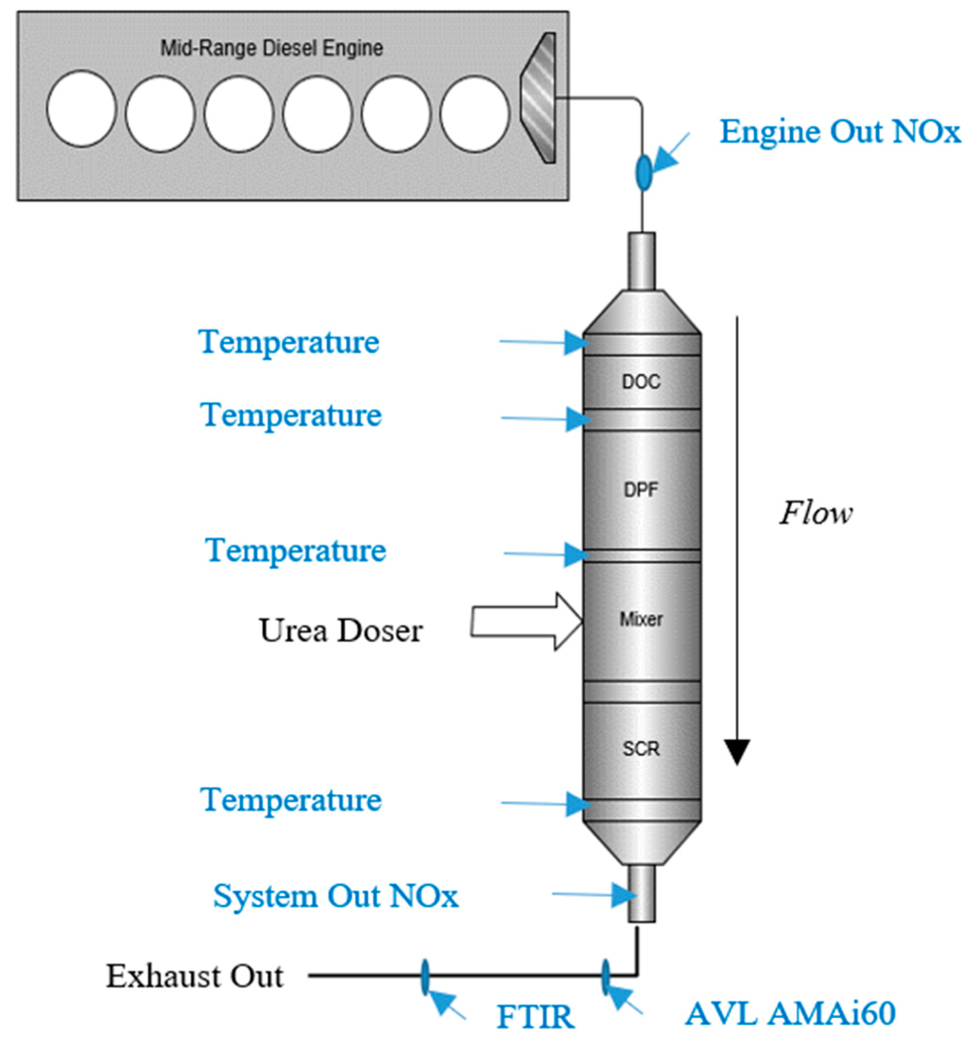
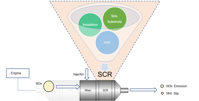
2.1. Aftertreatment Architecture and Test Setup

Figure 1 shows the aftertreatment architecture and test setup used in this experimental study. This complex aftertreatment system has a DOC+DPF+SCR scheme for a non-road mid-range diesel engine, using a urea doser installed on the mixer to inject ammonia into the aftertreatment system when necessary under the control strategy under different engine conditions to achieve the best NOx conversion efficiency. The mixer aims to guarantee the efficient use of urea with an optimum distribution across the catalyst, and the mixer is integrated in the aftertreatment system by clamps. In this experimental setup, the exhaust flow comes out from turbocharger of a nonroad 6-cylinder engine and enters the aftertreatment inlet tube. The exhaust gas then goes across the catalysts (DOC, DPF, SCR) to the aftertreatment outlet tube. In-cylinder post injection is applied in the control strategy for active DPF regeneration. The connection pipe between the turbocharger and the aftertreatment inlet is assumed to be 1.5 m in length per typical non-road applications.
The urea pyrolysis mechanism and droplet evaporation involve complex reactions. The urea droplets would begin to evaporate with rising temperature after being gradually heated by exhaust gas. Urea can be directly pyrolyzed from the solid or liquid phase, as the water starts to evaporate from the aqueous urea solution at the earliest point in time due to its lower boiling point.
In a word, the urea droplets are heated up and water evaporates first, followed by the thermolysis of urea into ammonia and isocyanic acid [23]:
(NH2)2 CO(aq) → (NH2)2 CO(l) + H2O(g)
(NH2)2 CO(l) → NH3 (g) + HNCO(g)
The main reactions in SCR would require that NH3 and NOx to be mixed under stoichiometric conditions (shown in Equations (3)–(5)) to achieve high NOx conversion efficiency:
4NH3 + 4NO + O2 → 4N2 + 6H2O (Standard Reaction)
4NH3 + 3NO2 → (7/2)N2 + 6H2O (Slow Reaction)
4NH3 + 2NO + 2NO2 → 4N2 + 6H2O (Fast Reaction)
In this experimental setup, two NOx sensors are installed to measure the engine out NOx emissions and system out NOx emissions. The NOx conversion efficiency could be calculated accordingly from these two test values. The engine which is applied in these experiments is a 6-cyliner Diesel engine without EGR, using a turbocharged intake system.

2.2. Experimental Methodology

There are a comprehensive research experimental tests guiding how to determine the appropriate SCR size for a non-road mid-range diesel engine with a given SCR diameter. In the series of experimental tests, catalysts would be considered as aged and fresh for different specific tests. When considering aged conditions, the catalysts are aged according to catalyst coating content and the non-road duty cycle requirements which are aged specifically for 50 h under 650 °C using a hydrothermal method in a catalyst aging oven for all catalysts. The NRTC emission cycle is applied in these experiments. Figure 2 shows the parameter variation in an NRTC emission cycle which is in total 1238 s in duration.
Three aftertreatment system concepts of with different SCR lengths using the same SCR diameter are introduced in this study and the aftertreatment packaging is the same in all these concepts. To make sure the sizing strategy is efficient, only the SCR is varied and all other parts (DOC, DPF, mixer. etc.) are the same in all the experiments.
Figure 3 illustrates all the concepts, and the SCR specifications matrix in the experiments is detailed in Table 1. The catalyst has a honeycomb structure.
The urea dosing starting temperature is set as 230 °C in the control strategy and base ANR is 0.95. This strategy is considered as base dosing strategy for the experiments in this paper. We research in these experiments the aftertreatment system inlet/outlet insulation impact on the system emission results. The insulation is packaged on the surface of each catalyst module according to the appropriate size. Table 2 shows the insulation specifications.
When considering the SCR substrate impact on the system emission results, the aftertreatment system of Concept 2–1 is introduced into this experimental. Concept 2–1 is generated based on Concept 2, the only difference between these two concepts being the SCR cell density. The SCR cell density is 600 cpsi in Concept 2, and the SCR cell density is 400 cpsi in Concept 2–1. Table 3 specifies the SCR specifications for Concept 2 and Concept 2–1.
The NOx conversion efficiency deviation with these two SCR substrates concepts is investigated under different system conditions. The conditions specifications are shown in Table 4.
In this experimental research, an AVL AMAi60 instrument is equipped as the NOx emission analyzer. The exhaust gas is introduced into a Horiba Fourier transform infrared (FTIR) spectroscopy system which is used for NH3 analysis to obtain the NH3 slip results. The measurement range is 0–1000 ppm for the two analyzers and these two main analyzers are calibrated for an allowable measurement error within ± 2%. Considering the variations of the whole test setup, the maximum permitted measurement error is within ± 8%. Each test was conducted at least three times and the repeatability of the measurement results was checked. The results which were deemed repeatable were used for the analysis.

3. Results and Discussions

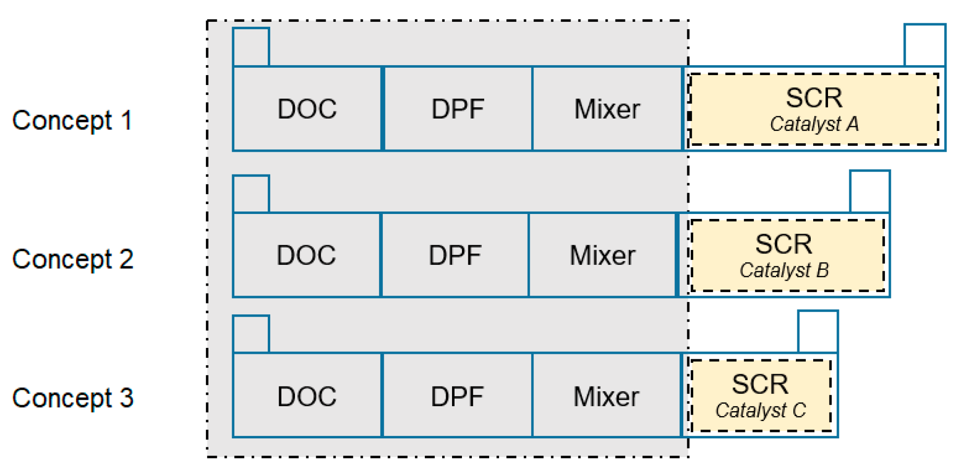
3.1. System Emission Results with Different SCR Size Concepts

Figure 4 shows NOx conversion efficiency results with different SCR size concepts during NRTC. Figure 5 shows the average NH3 slip with the three concepts during NRTC:
(1)
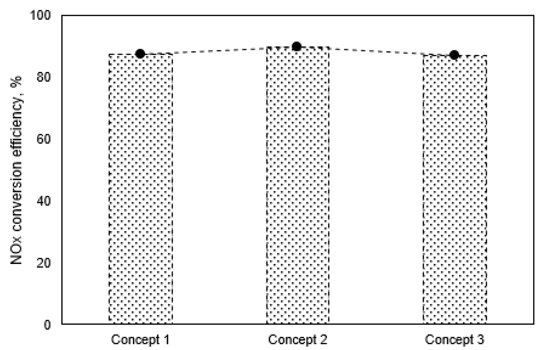
The NOx conversion efficiency is very similar for these three concepts. It could be observed that the NOx emission performance can meet the regulation requirement, and the cumulative NOx emission would be the similar for Concept 1, Concept 2 and Concept 3, when the system urea dosing strategy is the same. These three concepts with different SCR length demonstrate the SCR capability for NOx conversion.
(2)
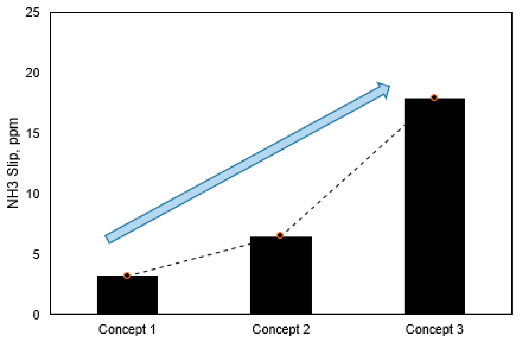
The average NH3 slip during NRTC varies greatly among these three concepts. The average NH3 slip during NRTC is quite low when applying Concept 1 and there is large margin to meet the regulation limit (25 ppm). As the SCR length becomes shorter, the average NH3 slip during NRTC increases. When the SCR length is much shorter, the average NH3 slip result shows a much quicker increase. Concept 1 displays the largest SCR size among the three concepts, which results in better capability for NH3 storage compared with Concept 2 and Concept 3. That results in much less average NH3 slip during NRTC by applying aftertreatment system with Concept 1.
(3)
The average NH3 slip during NRTC is nearly to 20 ppm when applying an aftertreatment system with Concept 3, which would risk exceeding the regulation limit if a shorter SCR length were used based on Concept 3. It can be regarded that the SCR length in Concept 3 is the shortest length to meet the NOx emission limit and NH3 slip limit in the regulation in these experiments.
With the same control and urea dosing strategy, these three concepts with different SCR length can meet the NOx emission and NH3 slip regulation requirements when performing a NRTC emission cycle. According to the above analysis, the emission results could meet China Stage IV regulation limits for NOx emissions and NH3 slip by applying the aftertreatment with Concept 2. When considering real applications, a shorter length of the whole aftertreatment system would be required due to limited installation space on non-road application vehicles. The shorter catalyst could bring lower cost in real applications. Therefore, the aftertreatment with Concept 2 is recommended due to cost and installation space limits, as well as technical robustness of its emission capability. The aftertreatment with Concept 3 could be regarded to have the shortest SCR length which can meet regulation requirements and it is suggested to pay attention to the NH3 slip risk if there is large variation in the whole system.
There were many studies that investigate the factors which impact NOx emission and NH3 slip, especially the temperature influence, as well as the functions of ASC [24,25,26]. In these experiments, the SCR temperature during NRTC is kept within a 250 °C to 400 °C range in most of the real application conditions. In this temperature range, the SCR catalyst could generally achieve the required NOx conversion efficiency with Cu-zeolite under a stable control strategy [27]. The ASC concept is generated based on Concept 3. The total SCR length (d) in the ASC concept includes SCR and ASC, and the ASC length is 0.5 d. The total SCR length in this ASC concept is the same as the length in Concept 3, that is d = c. Figure 6 shows cumulative NOx emission results and average NH3 slip results during NRTC in Concept 3 and with the ASC concept.
It can be seen that the average NH3 slip during NRTC exceeds the regulation limit (25 ppm) in this ASC concept and increases by 45% compared to that in Concept 3. The cumulative NOx emission with the ASC concept increase by 29% compared to that in Concept 3, although the NOx emission is still within the regulation limit. The SCR length in ASC concept is very short and is half the length of that in Concept 3. As a result, when applying this ASC concept, the engine out NOx could not be mixed using the same conditions as in Concept 3.

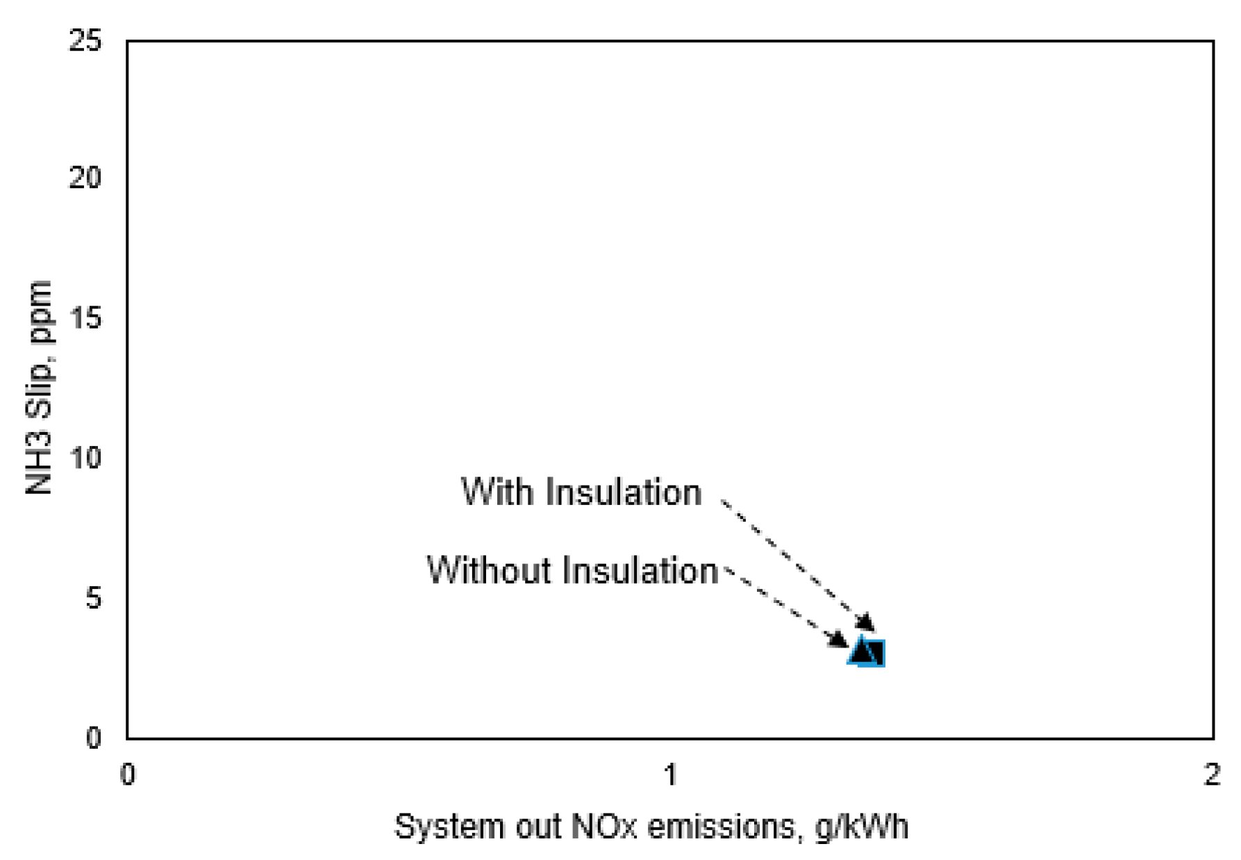
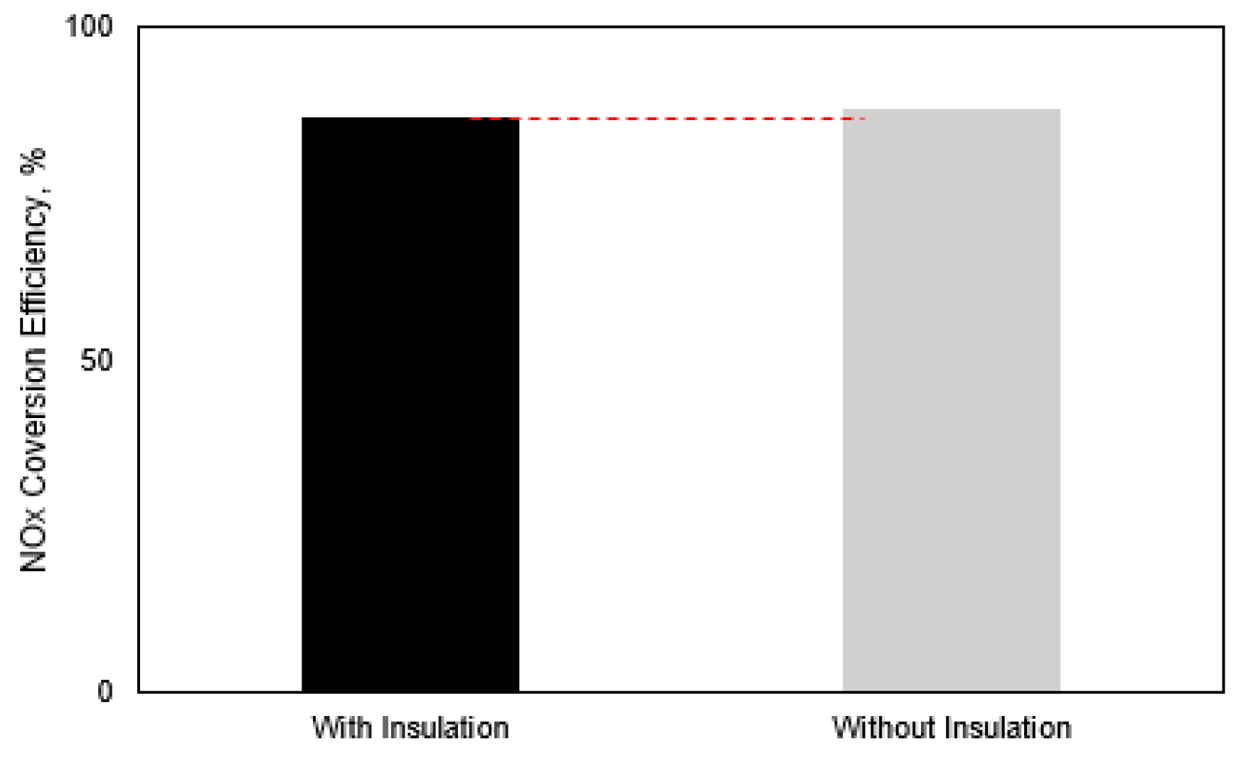
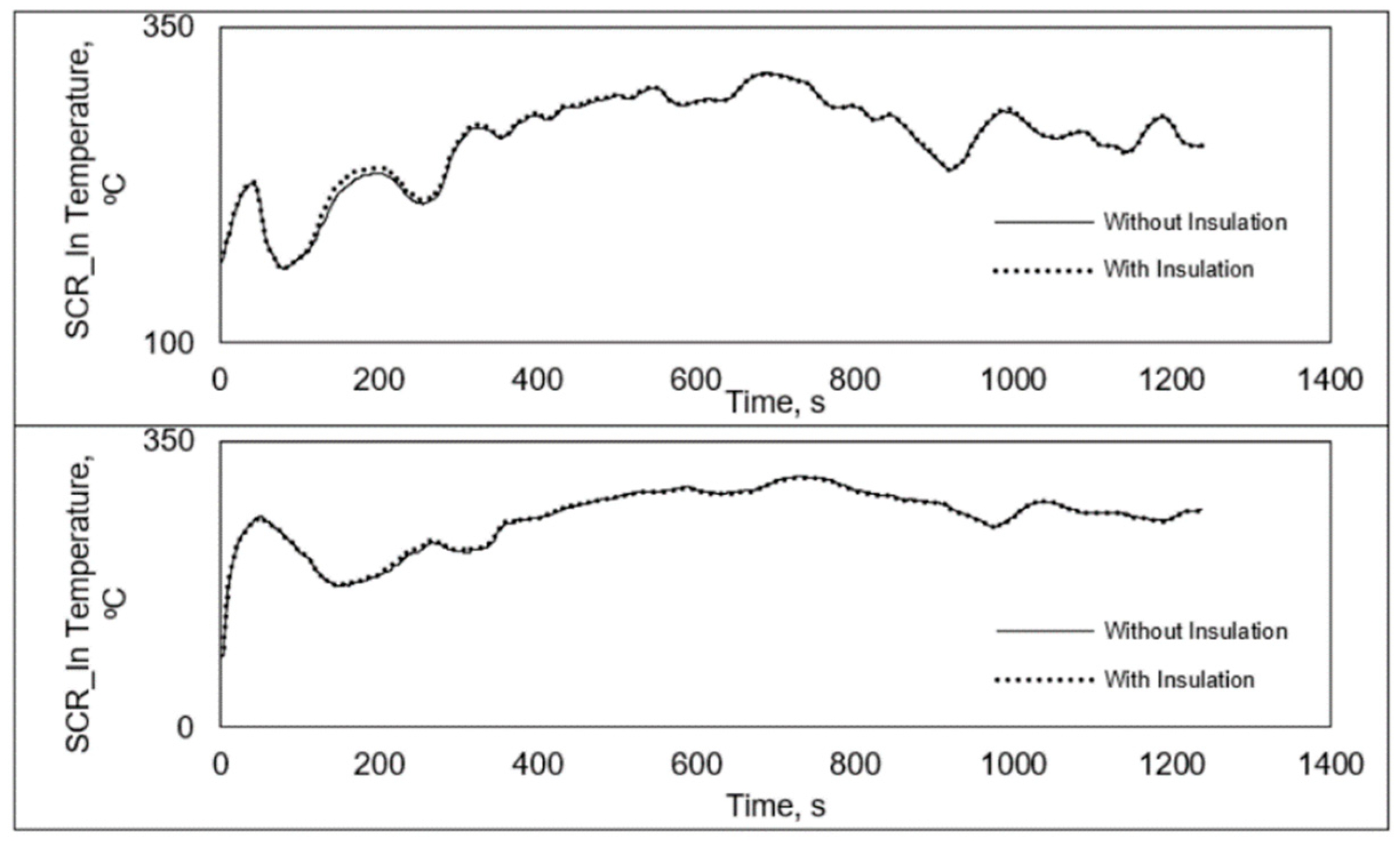
3.2. Inlet/Outlet Insulation Impact on System Emission Results

The aftertreatment concepts in these experimental tests are without insulation on the inlet and outlet package. In this experimental part, we add insulation to the aftertreatment inlet and outlet based on Concept 1. Figure 7 shows cumulative system out NOx emissions and the average NH3 slip results during NRTC for the inlet/outlet with insulation and without insulation. Figure 8 shows the NOx conversion efficiency under these two concepts during NRTC.
(1)
The cumulative system out NOx emission is quite similar when applying the aftertreatment system including an inlet/outlet with insulation as that with inlet/outlet without insulation. The cumulative system out NOx emissions are lower than 1.5 g/kWh during NRTC, with the NOx conversion efficiency being about 84%, which meets the non-road China Stage IV proposed regulation emission limit (2.0 g/kWh).
(2)
The average NH3 slip during NRTC is also quite similar when applying the aftertreatment system by inlet/outlet with insulation as that using inlet/outlet without insulation. The average NH3 slip during NRTC is very low and meets the non-road China Stage IV proposed regulation emission limit (25 ppm).
The insulation is generally used to decrease heat losses and ensure the exhaust gas temperature is kept in a specific range, so that SCR catalyst performs with high efficiency under certain conditions. Figure 9 shows the exhaust gas temperature at points on SCR_In and SCR_Out during NRTC when applying the aftertreatment system using inlet/outlet with insulation compared with that obtained with an inlet/outlet without insulation. It is illustrated that the average exhaust gas temperature is in range of 250 °C to 265 °C at the points of SCR_In and SCR_Out. The exhaust gas temperature variation ratio is within ± 2% under these two conditions during NRTC. This slight exhaust gas temperature variation results in similar emission results by applying aftertreatment inlet/outlet with insulation and without insulation. The connection pipe between the engine turbocharger and aftertreatment inlet is very short in non-road applications, typically 1.5 m, and the connection pipe is designed with insulation on the surface. The average temperature drop from engine turbocharger to the aftertreatment inlet is around 20 °C under the full load cycle using the test setup employed in this research. The exhaust gas temperature could remain high throughout SCR to achieve an appropriate NOx conversion efficiency during NRTC.
In these experiments, there is little effect on emission results during NRTC when the aftertreatment inlet/outlet with insulation and without insulation and the emission results could meet the non-road China Stage IV regulation limit whether the inlet/outlet have insulation or not.

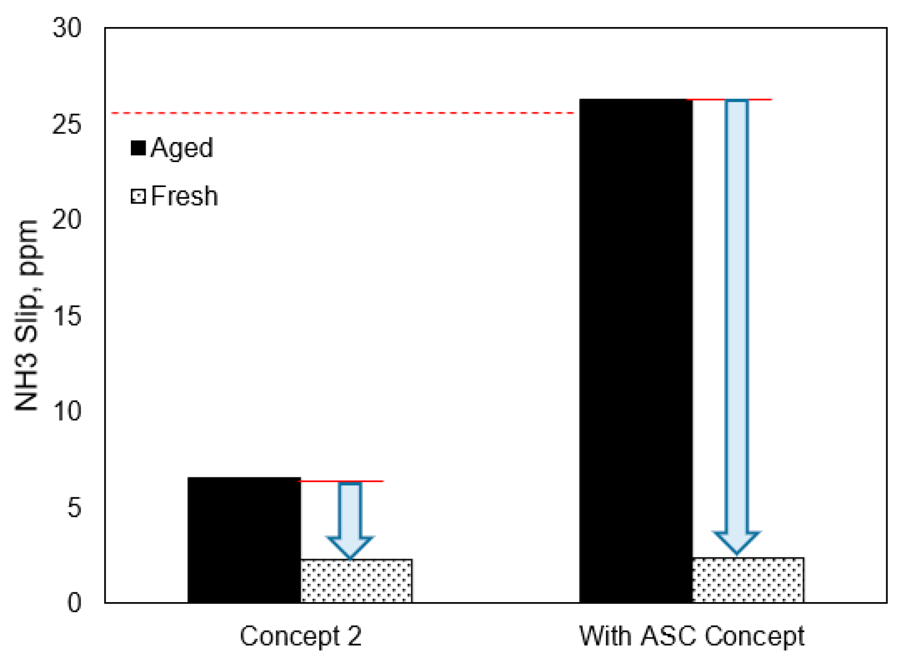
3.3. Catalyst Status Impact on System Emission Results

SCR catalyst performance degradation was validated after long use in real world application due to factors such as temperature, sulfur, duty cycle and so on [28]. The aftertreatment is suggested use aged catalysts in SCR sizing strategy experiments to estimate the useful emission control life in real world according to the regulation requirements. In this experimental part, we compare the emission results between aftertreatment system with aged catalysts and the system with fresh catalyst on the non-road mid-range diesel engine.
Figure 10 shows the NOx conversion efficiency results in Concept 2 and the ASC concept (total SCR length is d) with fresh catalysts and aged catalysts during the NRTC emission cycle. Figure 11 shows the NH3 slip test results in Concept 2 and the ASC concept with fresh catalysts and aged catalysts under the NRTC emission cycle.
(1)
Taking Concept 2 into consideration, it could be observed that the NOx conversion efficiency will be improved by about 2% when applying fresh catalysts compared to applying aged catalysts in the aftertreatment system. It could also be found that the average NH3 slip test results during NRTC are in the low range (less than 10 ppm) under all conditions in these experimental tests. This could prove that the SCR in Concept 2 is capable of converting NOx to meet the regulation standard, while has enough NH3 storage capability with the SCR size to lower NH3 slip even without ASC. A similar NOx conversion efficiency trend could be found in the ASC concept.
(2)
As for the ASC concept, it could be seen that with a fresh catalyst aftertreatment system, the emission results could easily meet the regulation limitations on NOx emissions and NH3 under the NRTC emission cycle conditions. However, the NH3 slip exceeds the regulation limit (25 ppm) with aged catalyst aftertreatment with the same scheme. Although there is an ASC in concept, the total SCR length including ASC used in this experimental Diesel engine is short, which results in high NH3 slip as it is hard for the ASC with limited size to convert NH3.
It is thus recommended to apply the aged catalysts aftertreatment in the SCR sizing strategy to estimate the emission useful life performance in real applications, which would bring higher confidence to propose the appropriate SCR size for this non-road mid-range diesel engine.

3.4. Substrate Impact to System Emission Results
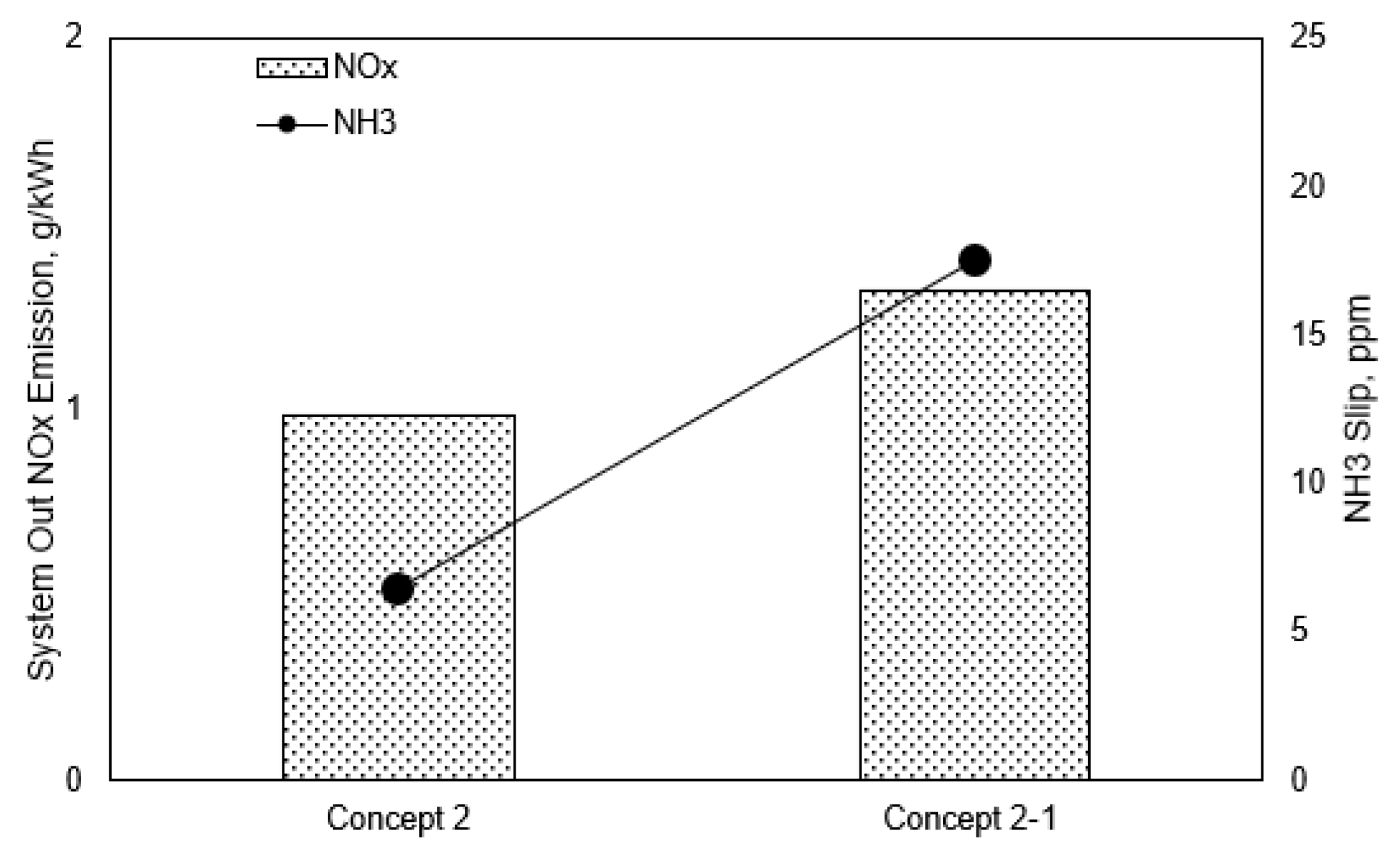
The aftertreatment concepts in these experimental tests are with a SCR cell density of 600 cpsi. We investigated the system emission with aftertreatment applying a SCR cell density of 400 cpsi (Concept 2–1) based on the aftertreatment system with Concept 2. Figure 12 shows the system out NOx emission results over time during NRTC with different SCR substrate concepts. During the whole NRTC emission cycle, the system out NOx emission result is higher with Concept 2–1 than with Concept 2. There is an obvious system out NOx variation from 600 s to 800 s when the engine speed is continuously high during this period in the NRTC emission cycle. The SCR temperature is high during this period, that makes the system out NOx emission still be low.
Figure 13 shows the cumulative NOx emission results and average NH3 slip results during NRTC with different SCR substrate concepts. It could be found that the cumulative NOx emission and average NH3 slip could meet regulation requirements by applying Concept 2 or Concept 2–1 and the emission results are higher by applying the aftertreatment system with Concept 2–1 compared to Concept 2 when the system urea dosing strategy is the same:
(1)
It can be seen that the system out cumulative NOx emission result during the NRTC emission cycle is about 30% higher with the aftertreatment system considering Concept 2–1 compared to Concept 2 and it could meet the regulation requirement (2.0 g/kWh) under both conditions.
(2)
The average NH3 slip results during NRTC show that they could meet the regulation requirement (25 ppm) under both conditions and the NH3 slip result during NRTC is nearly 20 ppm.
Figure 14 shows NOx conversion efficiency deviation with different SCR substrates concepts under three conditions in which the exhaust temperature and space velocity are different. The NOx conversion efficiency deviation is within 6% for the concept of SCR substrates with 400 cpsi cell density compared to that with 600 cpsi cell density, which shows that the NOx conversion efficiency is lower for the concept of SCR substrate with 400 cpsi cell density. That is mainly due to the fact the proportion is different with the two concepts. With the same SCR diameter, the catalyst holes proportion of the concept of SCR substrate with 400 cpsi cell density is less than that with 600 cpsi cell density, which results in less washcoat on the catalyst hole surface. This makes the NOx conversion opportunity less compared to that with 600 cpsi cell density, when the engine out NOx emission and dosing strategy are consistent for these two concepts.
It can be seen that by applying Concept 2 of SCR substrate with 600 cpsi cell density, the NOx emission and NH3 slip results could meet the regulation limits and the NOx conversion capability is stronger than that with 400 cpsi cell density when the SCR size is the same. Therefore, it shows that the SCR substrate with 600 cpsi cell density is better than with 400 cpsi in this experimental research considering the NOx emission and NH3 slip results during the NRTC emission cycle.

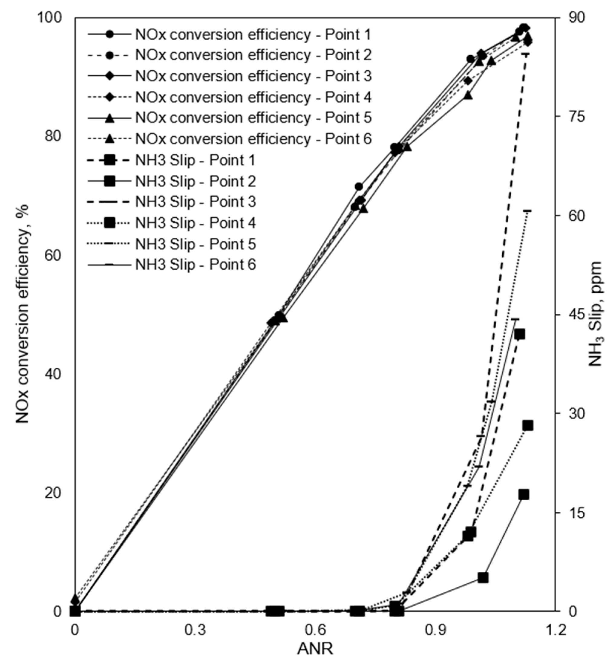
3.5. ANR to System Emission Results
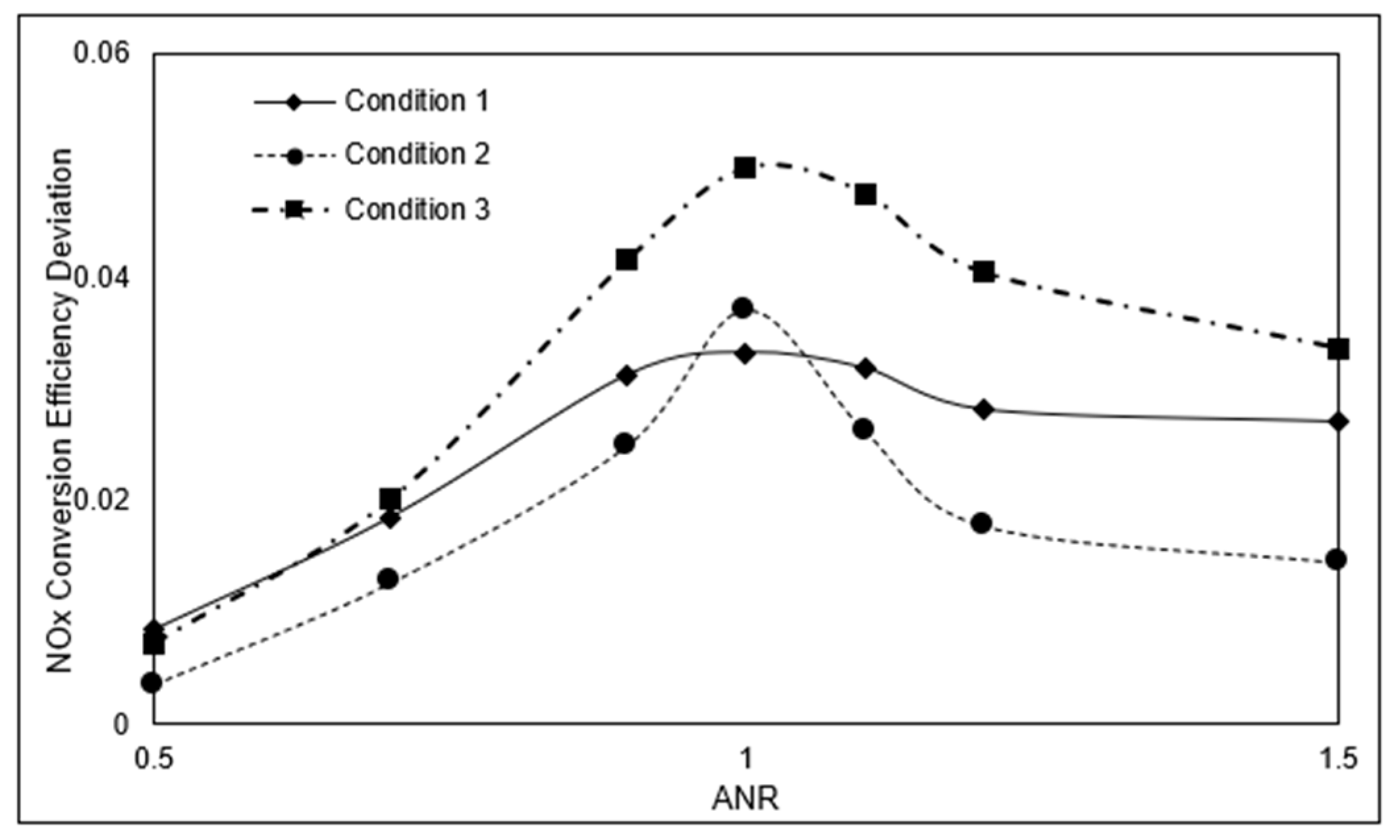
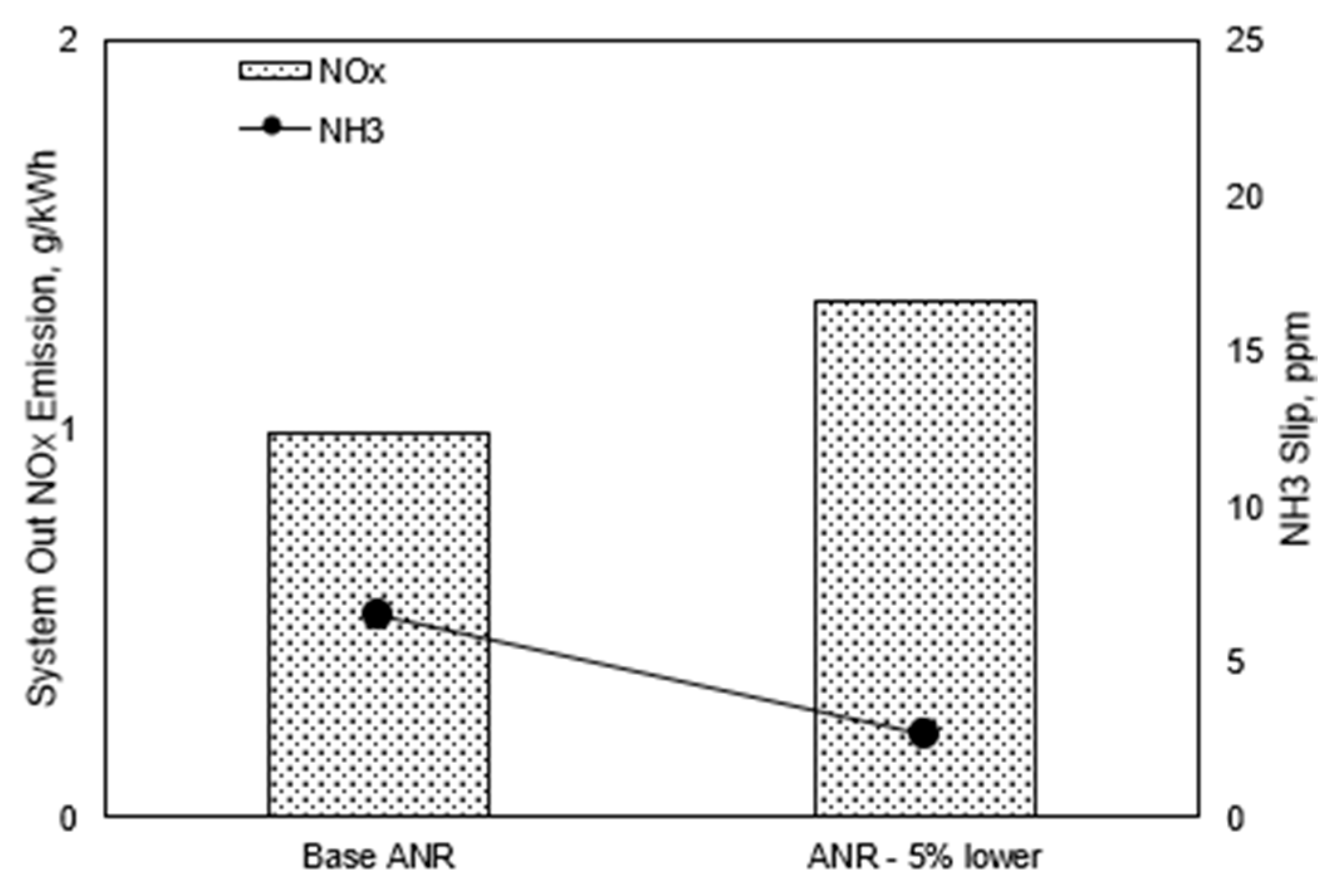
Figure 15 shows the cumulative NOx emission results and average NH3 slip results during NRTC considering ANR adjustment compared to the base dosing strategy. These experiments use aftertreatment with Concept 2. By reducing ANR by 5%, the cumulative NOx emission increases from around 1.0 g/kWh to about 1.5 g/kWh, which is still lower than 2.0 g/kWh and could meet the regulation limits. The system average NH3 slip decreases to less than 5 ppm when adjusting the ANR to 5% lower. Under the same aftertreatment concept, when decreasing the ANR, the amount of NOx would have less opportunity to be converted enough compared to using the base ANR.
As a result, the current dosing strategy for the aftertreatment system with Concept 2 would meet the regulation limits on NOx emissions and NH3 slip. We could adjust ANR in the dosing strategy according to the experimental results. In these experiments, we investigated the NOx conversion efficiency and NH3 slip under different ANR using aftertreatment with Concept 2. Typical boundary conditions are selected from a real off-highway application. Six points with different space velocity and temperature are chosen from the real application to define these boundary conditions, as shown in Figure 16. It shows that the SCR bed temperature is higher than 250 °C and the space velocity is within 150*103/h. Each point in Figure 16 stands for a specific typical condition, and these six points illustrate the boundary conditions which could be regarded to represent the real off-highway application conditions. Therefore, it is necessary to understand the emission results under these six conditions.
Figure 17 shows the NOx conversion efficiency and NH3 slip results by ANR under the six boundary conditions. Under a certain space velocity and temperature condition, as ANR increases, the NOx conversion efficiency increases and the NH3 slip increases too. Based on the reactions in SCR, the NH3 and NOx are mixed under stoichiometric conditions (shows in equations (3)–(5)) to achieve a high NOx conversion efficiency. When ANR increases to a higher value, there would be NH3 slip.
(1)
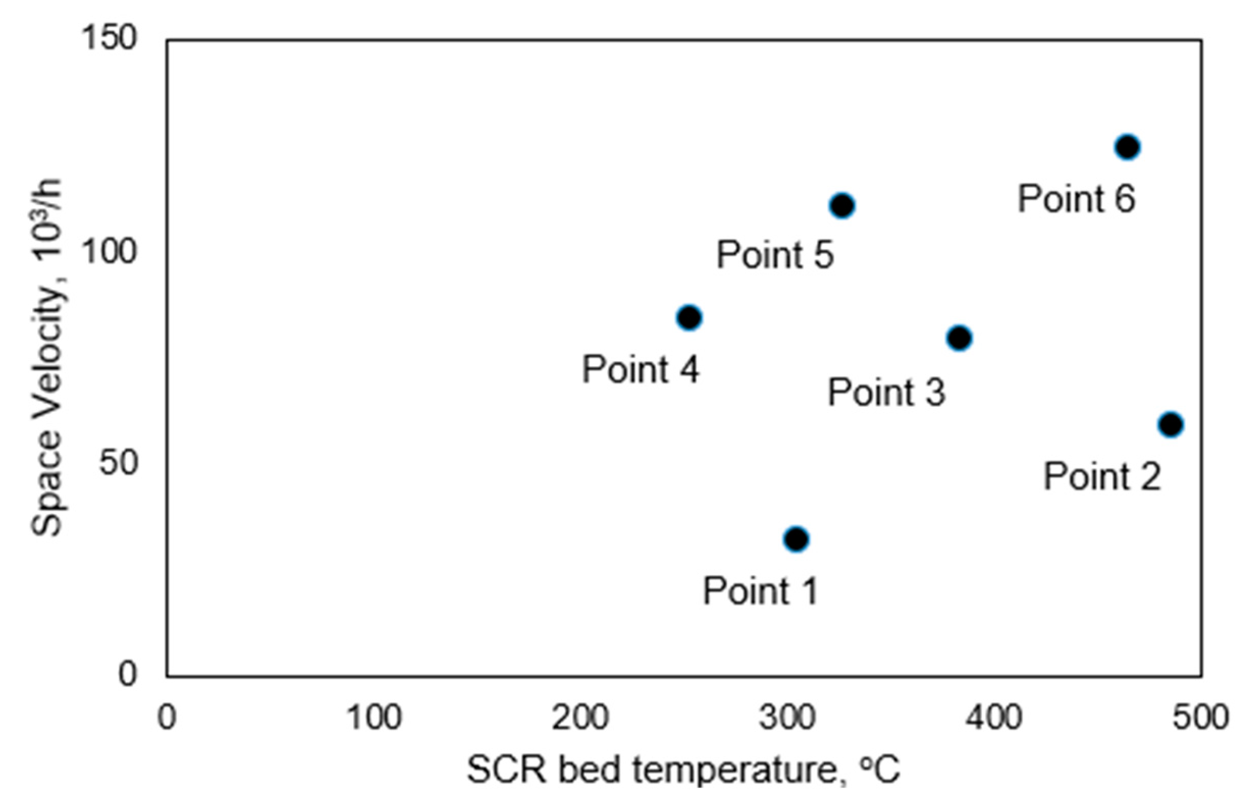
It could be found that the NH3 slip is very little and close to zero when ANR is below 0.8 under all six boundary conditions. When ANR is above 1.1, the NH3 slip under boundary conditions with Point 1, 3, 4, 5, 6 conditions, would be above 25 ppm which exceeds the regulation requirement in this experimental study. When ANR is between 0.8–0.9, the NH3 slip is very low under all six boundary conditions.
(2)
The NOx conversion efficiency becomes higher as ANR increases. When the ANR is higher than 0.9, the NOx conversion efficiency could reach above 80%.
Considering the regulation requirements on NOx emissions and NH3 slip, it would be recommended that the ANR be set in range of 0.9–1.1.

4. Conclusions

This paper presents a comprehensive experimental study on aftertreatment system NOx emissions and NH3 slip for different aftertreatment concepts considering the China non-road Stage IV emission regulations. It introduces a SCR sizing strategy for a 6-cylinder non-EGR mid-range Diesel engine for non-road applications, and provides alternative solutions to determine the SCR size in DOC+DPF+SCR scheme to meet the China Stage IV regulation requirements. Specifically, the findings include:
(1)
The three concepts could meet the regulation limits for NOx emissions and NH3 slip by selecting an appropriate length. It is suggested to use an aged catalyst system in SCR sizing research work when taking real world application into consideration.
(2)
There is little effect on emission results during NRTC when the aftertreatment inlet/outlet is with insulation or without insulation. The emission results with both strategies could meet the non-road China Stage IV regulation limits.
(3)
It is recommended to select Concept 2 which could meet the regulation requirements considering multiple factors in the SCR sizing strategy. Substrate impact and ANR impact are investigated based on Concept 2. The results show that by applying the aftertreatment of SCR substrate with 600 cpsi cell density, the NOx conversion capability is stronger than that with 400 cpsi cell density when the SCR size is the same. The current dosing strategy is capable and recommended ANR is 0.9–1.1 if considering dosing strategy optimization.
(4)
It can be regarded the SCR length in Concept 3 is the shortest length that can meet the NOx emissions limit and NH3 slip limit in the regulation in these experiments. Emission results during NRTC with the ASC concept are discussed based on Concept 3. As the total SCR length is short for the ASC concept, there is no optimization of the emission results in this case.
In the Chinese market, aftertreatment would be applied for the first time in non-road applications. It would be quite significant to develop shorter aftertreatment to meet the limited installation space available on vehicles and achieve lower cost, while guaranteeing the whole robustness of the system emission capabilities. This SCR sizing strategy helps to balance these complex requests for non-road applications. For further improvement, one could optimize the integrated control strategies with the selected SCR size.

Author Contributions

Conceptualization, L.X.; Formal analysis, L.X.; Methodology, L.X.; Project administration, F.Q.; Supervision, G.J.; Validation, L.X.; Writing—original draft, L.X.; Writing—review & editing, L.X. All authors have read and agreed to the published version of the manuscript.

Funding

This research was funded by Natural Science Foundation of Hubei Province (No. 2019CFB694) and Hubei Provincial Department of Education Science and Technology Research (No. B2018003).

Conflicts of Interest

The authors declare no conflict of interest.

References

  1. Emission Standards, “China: Nonroad Engines”. Available online: https://dieselnet.com/ (accessed on 30 June 2018).
  2. Xie, L.; Jiang, G.; Qian, F. Research on Aftertreatment Inlet_Outlet Insulation for A Nonroad Middle Range Diesel Engine. Catalysts 2020, 10, 454. [Google Scholar] [CrossRef] [Green Version]
  3. Chi, J.N. Control Challenges for Optimal NOx Conversion Efficiency from SCR Aftertreatment Systems. SAE Tech. Pap. 2009. [Google Scholar] [CrossRef]
  4. Sharp, C.; Webb, C.C.; Neely, G.; Sarlashkar, J.V.; Rengarajan, S.B.; Yoon, S.; Henry, C.; Zavala, B. Achieving Ultra Low NOX Emissions Levels with a 2017 Heavy-Duty On-Highway TC Diesel Engine and an Advanced Technology Emissions System—NOX Management Strategies. SAE Int. J. Engines 2017, 10, 1736–1748. [Google Scholar] [CrossRef]
  5. Rauch, H.; Rezaei, R.; Weber, M.; Kovacs, D.; Strots, V.; Bertram, C. Holistic Development of Future Low NOx Emission Concepts for Heavy-Duty Applications. SAE Tech. Pap. 2018. [Google Scholar] [CrossRef]
  6. Wang, T.J.; Kim, J.H. Simulation Study on Thermal Management Strategy to Achieve 99 % SCR Efficiency of a Heavy-Duty Diesel Engine over a Transient Cycle. Int. J. Automot. Technol. 2018, 19, 597–603. [Google Scholar] [CrossRef]
  7. Harris, T.M.; Mc Pherson, K.; Rezaei, R.; Kovacs, D.; Rauch, H.; Huang, Y. Modeling of Close-Coupled SCR Concepts to Meet Future Cold Start Requirements for Heavy-Duty Engines. SAE Tech. Pap. 2019. [Google Scholar] [CrossRef]
  8. Munnannur, A.; Chiruta, M.; Liu, Z.G. Thermal and Fluid Dynamic Considerations in Aftertreatment System Design for SCR Solid Deposit Mitigation. SAE Tech. Pap. 2012. [Google Scholar] [CrossRef]
  9. Zheng, G.; Wang, F.; Wang, S.; Gao, W.; Zhao, Z.; Liu, J.; Wang, L.; Wu, L.; Wang, H. Urea SCR System Development for Large Diesel Engines. SAE Tech. Pap. 2014. [Google Scholar] [CrossRef]
  10. Drennan, S.; Kumar, G.; Quan, S.; Wang, M. Application of Automatic Meshing to Urea-Water Injection Simulation for Engine Aftertreatment. SAE Tech. Pap. 2015. [Google Scholar] [CrossRef]
  11. Kamasamudram, K.; Yezerets, A.; Chen, X.; Currier, N.; Castagnola, M.; Chen, H.-Y. New Insights into Reaction Mechanism of Selective Catalytic Ammonia Oxidation Technology for Diesel Aftertreatment Applications. SAE Int. J. Engines 2011, 4, 1810–1821. [Google Scholar] [CrossRef]
  12. Ottinger, N.; Foley, B.; Xi, Y.; Liu, Z.G. Impact of Hydrocarbons on the Dual (Oxidation and SCR) Functions of Ammonia Oxidation Catalysts. SAE Int. J. Engines 2014, 7, 1262–1268. [Google Scholar] [CrossRef]
  13. Xu, L.; McCabe, R.; Ruona, W.; Cavataio, G. Impact of a Cu-zeolite SCR Catalyst on the Performance of a Diesel LNT+SCR System. SAE Tech. Pap. 2009. [Google Scholar] [CrossRef]
  14. Sato, S.; Sato, S.; Hosoya, M. Improvement of Low-Temperature Performance of The NOx Reduction Efficiency on the Urea-SCR Catalysts. SAE Tech. Pap. 2013. [Google Scholar] [CrossRef]
  15. Kim, P.S.; Kim, Y.J.; Kim, C. Development of Ultra-Stable Cu-SCR Aftertreatment System for Advanced Lean NOx Control. SAE Tech. Pap. 2019. [Google Scholar] [CrossRef]
  16. Pless, J.D.; Naseri, M.; Klink, W.; Spreitzer, G.; Chatterjee, S.; Markatou, P. Development of SCR on High Porosity Substrates for Heavy Duty and Off-Road Applications. SAE Int. J. Commer. Veh. 2014, 7, 177–185. [Google Scholar] [CrossRef]
  17. Cheng, Y.; Huang, Y. Deactivation of Cu/Zeolite SCR Catalyst under Lean-Rich Aging Conditions. SAE Tech. Pap. 2010. [Google Scholar] [CrossRef]
  18. Hou, X.; Epling, W.S.; Schmieg, S.; Li, W. Cu-Zeolite SCR Catalyst Thermal Deactivation Studied with FTIR Spatial Resolution. SAE Int. J. Engines 2011, 4, 1298–1318. [Google Scholar] [CrossRef]
  19. Chen, X.; Currier, N.; Yezerets, A.; Kamasamudram, K. Mitigation of Platinum Poisoning of Cu-Zeolite SCR Catalysts. SAE Int. J. Engines 2013, 6, 856–861. [Google Scholar] [CrossRef]
  20. Xi, Y.; Ottinger, N.A.; Liu, Z.G. Effect of Hydrothermal Aging on the Catalytic Performance and Morphology of a Vanadia SCR Catalyst. SAE Tech. Pap. 2013. [Google Scholar] [CrossRef]
  21. Stadlbauer, S.; Waschl, H.; Del Re, L. Adaptive SCR Model for MPC Control Including Aging Effects. SAE Tech. Pap. 2015. [Google Scholar] [CrossRef]
  22. Ohya, N.; Hiyama, K.; Tanaka, K.; Konno, M.; Tomita, A.; Miki, T.; Tai, Y. Kinetic Modeling Study of NOx Conversion Based on Physicochemical Characteristics of Hydrothermally Aged SCR/DPF Catalyst. SAE Int. J. Fuels Lubr. 2017, 10. [Google Scholar] [CrossRef]
  23. Birkhold, F.; Meingast, U.; Wassermann, P.; Deutschmann, O. Analysis of the Injection of Urea-Water-Solution for Automotive SCR DeNOx-Systems: Modeling of Two-Phase Flow and Spray/Wall-Interaction. SAE Tech. Pap. 2006. [Google Scholar] [CrossRef] [Green Version]
  24. Jacques, J.; Pauly, T.; Zammit, M.; Ahari, H.; Smith, M. Robust SCR Design Against Environmental Impacts. SAE Tech. Pap. 2016, 1. [Google Scholar] [CrossRef]
  25. Ottinger, N.; Schmidt, N.; Liu, Z.G. Understanding System- and Component-Level N2O Emissions from a Vanadium-Based Nonroad Diesel Aftertreatment System. SAE Int. J. Engines 2017, 10, 1808–1814. [Google Scholar] [CrossRef]
  26. Su, C.; Brault, J.; Munnannur, A.; Liu, Z.G.; Milloy, S.; Harinath, A.; Dunnuck, D.; Federle, K. Model-Based Approaches in Developing an Advanced Aftertreatment System: An Overview. SAE Tech. Pap. 2019, 1. [Google Scholar] [CrossRef]
  27. Maunula, T.; Wolff, T. Durable Copper and Iron SCR Catalysts for Mobile Diesel and Dual-Fuel Applications. SAE Tech. Pap. 2016, 1. [Google Scholar] [CrossRef]
  28. Hruby, E.; Huang, S.; Duddukuri, R.; Dou, D. NOx Performance Degradation of Aftertreatment Architectures Containing DOC with SCR on Filter or Uncatalyzed DPF Downstream of DEF Injection. SAE Tech. Pap. 2019. [Google Scholar] [CrossRef]
Figure 1. Aftertreatment architecture and test setup scheme.
Energies 13 04462 g001
Figure 2. Parameter variation in an NRTC emission cycle.
Energies 13 04462 g002
Figure 3. Aftertreatment SCR sizing concepts in the experiments.
Energies 13 04462 g003
Figure 4. NOx conversion efficiency results during NRTC with different SCR size.
Energies 13 04462 g004
Figure 5. NH3 slip results during NRTC with different SCR size.
Energies 13 04462 g005
Figure 6. NOx emission results and NH3 slip results considering ASC concept.
Energies 13 04462 g006
Figure 7. NOx emission and NH3 lip results with insulation and without insulation during NRTC.
Energies 13 04462 g007
Figure 8. NOx conversion efficiency results with insulation and without insulation.
Energies 13 04462 g008
Figure 9. Exhaust gas temperature results with insulation and without insulation.
Energies 13 04462 g009
Figure 10. NOx conversion efficiency results during NRTC with aged catalysts vs. fresh catalysts.
Energies 13 04462 g010
Figure 11. NH3 slip results during NRTC with aged catalysts vs. fresh catalysts.
Energies 13 04462 g011
Figure 12. System out NOx emission during NRTC with different SCR substrate concepts.
Energies 13 04462 g012
Figure 13. NOx emission results and NH3 slip results during NRTC with different SCR substrate concepts.
Energies 13 04462 g013
Figure 14. NOx conversion efficiency deviation with different SCR substrate concepts.
Energies 13 04462 g014
Figure 15. NOx emission results and NH3 slip results during NRTC considering ANR adjustment.
Energies 13 04462 g015
Figure 16. Typical boundary conditions.
Energies 13 04462 g016
Figure 17. NOx conversion efficiency and NH3 slip by ANR.
Energies 13 04462 g017
Table 1. SCR specifications matrix in the experiments.
ConceptMaterialWashcoatDiameter, (in)Cell density, (cpsi)ASCLength, (in)
1CordieriteCu-zeolite10.5600Withouta
2CordieriteCu-zeolite10.5600Withoutb = 0.75a
3CordieriteCu-zeolite10.5600Withoutc = 0.5a
Table 2. Insulation specifications.
SpecificationsDescription
MaterialStainless steel
Thickness1.2 mm
Table 3. SCR specifications for Concept 2 vs. Concept 2–1.
ConceptMaterialWashcoatDiameter, (in)Cell density, (cpsi)ASCLength, (in)
2CordieriteCu-zeolite10.5600Without0.75a
2–1CordieriteCu-zeolite10.5400Without0.75a
Table 4. Conditions specifications.
ConditionSpace Velocity, (103/h)SCR Bed Temperature, (°C)
126080
2390110
3320110

