Abstract
In this paper, a simulations model of a seasonal thermal energy storage (TES) reactor integrated into a house heating system is presented. The water vapour chemisorbing reactor contains a composite material composed of silica gel and hydrated magnesium carbonate (nesquehonite, MgCO3·3H2O) that can be produced by a carbon capture and storage by mineralisation process. The performance of the TES to supply winter heat instead of electrical resistance heat is analysed. Dividing the reactor into a few units (connected in series) for better heat output and storage capacity as developed by the authors is compared to one unit or parallel unit solutions. The heating system components are an exhaust air heat pump, solar collectors and a heat recovery ventilation unit (HRV). The TES is used as heat source during colder periods, which implies improved efficiency and coefficient of performance (COP). Around 70% of electrical resistance heat, assisting an exhaust air heat pump during cold periods, can be substituted with heat from the TES according to the simulation model. Connecting three units in series will increase the usable storage capacity possibilities with by a 49% higher heat output.
1. Introduction
All technically and economically viable types of renewable energy and carbon capture and storage (CCS) technologies are necessary measures to reach the goals of the 2015 Paris climate agreement on reduced CO2 emissions. The availability of renewable energy sources often fluctuates and solar heat largely exceeds the heating demand during summer, while the major demand for heat is during winter. Solving this problem requires seasonal energy storage, for example for heat in the form of thermal energy storage (TES), within affordable volume boundaries. Usage of water tank thermal storage for buildings is already taking place, and studies show that water tanks (and gravel) can offer a 60% efficiency of re-using stored energy with large underground tanks [1]. In more densely built areas, the storage volume can be an issue and using chemical sorption reaction based seasonal storage would require smaller volumes, with larger energy density compared to sensible heat storage.
In this paper, simulations of a novel type of TES heating concept are presented using laboratory data from our earlier studies. The material used in the seasonal thermal energy storage (STES) reactor is a composite that is composed by 1/2 (by mass) of silica gel (SG) and 1/2 of a magnesium carbonate hydrate, nesquehonite (NQ) MgCO3∙3H2O [2]. Studies show that a carbon capture and storage by mineralisation (CCSM) process [3] can leach mineral magnesium (in aqueous [4] and non-aqueous [5] solution) and produce NQ abundantly [6] which is then further mixed with silica gel [7]. The concept of the simulations in this paper is essentially based on is an exhaust air heat pump (EAHP) heating system with a STES reactor added, resulting in the required increase in the relative humidity (RH) in the reactor, as described in detail below in Section 2 of this paper [8].
Besides NQ, studies by others have shown that the TES capacity of some materials (e.g., NQ, SG, MgSO4 and Al2(SO4)3) is reduced in conventional open systems using exhaust/outlet air with lower RH [8,9,10]. However, the lower water vapour content as specific humidity (SH, kg moisture/kg dry air, not the same as low RH) mostly affects the more costly zeolite. Moreover, studies show that using a zeolite in a closed (more expensive) system could cover 70% of the energy use in central Europe [11]. Adding a TES system based on a water vapour adsorption reactor in a house heating system has great potential, considering that around 10% of the heating in a modern house (under Nordic conditions) is lost as moisture despite some condensation in heat recovery ventilation [12].
Several sorption materials for TES have been studied in this field and zeolites were repeatedly shown to be suitable. The thermal storage capacity achieved is around 1.0 MJ/kg at relatively high desorption/charging temperatures of 100–140 °C [13,14,15]. However, several affordable salts would be a cheap alternative for zeolites for STES that would require large volumes [14].
Various crystalline salts based on of MgCl2 have been studied and granulates in a packed bed with 50% porosity give a theoretical storage capacity of 1 GJ/m3, while experiments gave a storage capacity of 0.5 GJ/m3 [9]. However, formation of hydrochloride acid as a result of material degradation occurs at temperatures above 100 °C when using MgCl2 [16].
The more affordable desiccant silica gel (SG) has also been shown to be a suitable TES material with efficient dehydration at 65–105 °C and a storage capacity around 0.6 MJ/kg [1,14,17]. The data of the thermodynamic properties of NQ used in this paper are primarily from our recent studies while hardly any other thermodynamic data can be found. The theoretical capacity storage capacity for NQ reacting according to reaction (R1) is 1.0 MJ/kg. However, based on data from a mixture with NQ and SG heated to 65 °C for dehydration, the maximum heat capacity for SG alone equals 0.52 MJ/kg [17,18].
MgCO3(s) + 3H2O(g) ↔ MgCO3∙3H2O(s)
ΔH = −1.00 MJ/kg MgCO3∙3H2O, T = 25 °C
ΔH = −1.00 MJ/kg MgCO3∙3H2O, T = 25 °C
Shown in our earlier studies, the main advantage of including SG in the materials is that it increases the hydration (according to R1) conversion by creating a better transport and contact structure for the water vapour to react with the NQ while formation or presence of liquid water is avoided [8]. The low desorption temperature (compared to e.g., zeolite) for NQ, being preferably at least 60 °C and, most likely, the low price are very important advantages in house or office building heating systems. Moreover, it should be mentioned that NQ is known to have flame retardant properties as a result of releasing CO2 and H2O at elevated temperatures [8,19]. The lower operating temperatures for a TES process decrease heat losses and enable more types of heat sources such as modern low temperature district heat (30 or 70 °C) or solar collectors during cloudy days and morning/evening sun) [12]. Several relevant review papers were published recently, which all involve dehydration temperatures above 100 °C using materials such as MgSO4, MgCl2, and CaCl2 [9,13,14,15,16,20,21]. In cases where district heat is used, the dehydration temperature should not exceed 100 °C (and even lower in the summer, around 70 °C).
In this paper, simulations and reactor systems analysis are reported for a process concept for seasonal thermal energy storage (STES) in a residential house. Moreover, a method for improving the efficiency of an adsorption STES reactor was developed and presented. The process concept was earlier developed and published by the authors [2,8].
2. Concept of Energy Storage System
Several concepts of TES by chemisorption include some type of reactor for heating inlet air directly or indirectly via heat exchange with exhaust air [14,15]. Very low indoor relative humidity (RH) during a heating period compromises the storage capacity, depending on the TES material(s) used [8,10]. The RH of the outlet air is increased as the temperature decreases during the heat collection in an exhaust air heat pump (EAHP). The concept based on (R1) was developed and published in our earlier studies, basically consisting of a TES reactor integrated with a typical EAHP heating system according to Figure 1. The heat pump receives exhaust air and collects heat by cooling down the exhaust air to e.g., 4 °C giving a suitable 50–100% RH for the chemisorption reactor containing the mixture of NQ and SG [8].
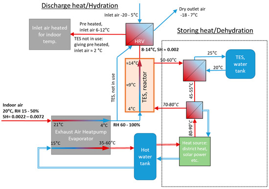
Figure 1.
Process scheme of the concept presented in earlier work. Thermal energy storage reactor combined with an auxiliary heat pump. Simple line arrows contain gas/air flow, double lined arrows contain liquid [2,8].
This concept basically consists of the TES reactor (with one fan) and a summertime heat source (e.g., solar collectors) as an extension to a standard EAHP system. For more than 10 years, EAHPs have been a common heating system solution in new houses (both small and apartment blocks), and a combination with STES is obviously attractive. The TES reactor can only operate in combination with the EAHP as it requires a high RH.
The heat generated in the reactor gives a temperature increase of 5–8 °C (with 20–40% RH air at 21 °C), depending on specific humidity (kg moisture/kg dry air) of the air received from the EAHP. The heat is transferred to the inlet air by a heat exchanger, i.e., a heat recovery ventilator (HRV). In this way, the TES reactor decreases the energy needed for heating the inlet air flow. Compared to the EAHP heat output alone, TES adds 20–30% heating, depending on the RH of the indoor air [8].
The most important source of available water vapour is excess moisture from indoor activities (showering, cooking, plants, humans, pets, etc.). However, by chemisorption from exhaust air, the outdoor ambient air can also be a water vapour source, considering that while using a TES sorption system, the specific humidity (SH) of house ventilation systems inlet (ambient) air can be higher than the outlet air. Assuming efficient sorption, this allows for using the same concept.
Considering that the reactor requires certain amounts of water vapour in the exhaust air, the system works best in fairly humid regions. Dry inland regions with a long very cold period in the winter (temperatures below –15 °C), will result in very low heat output; therefore e.g., northern Europe and humid coastal areas are suitable for open adsorption reactors.
An EAHP heating system requires an auxiliary heat source especially during winter and usually electrical resistance heating is used, intensifying the peaks of the heating demand during winter [22]. This could be avoided or lessened with STES, assisting the EAHPs during winter, possibly increasing the typical coefficient of performance (COP) to around 3.0–3.6 for an EAHP during STES operation [23]. A standard EAHP system with solar collectors would cost between EUR 10,000 and 15,000. Adding only the TES reactor would include the TES material cost of at least a few 1000 EUR; this of course would be cheaper for a new house-build.
The performance of this concept is simulated in this paper on a yearly heat use basis with various reactor configurations for which heat effects and capacity are discussed.
3. Methods
3.1. Modelling of the Concept
The calculations are based on a passive house with 100 m2 floor surface, at minimum ventilation (air residence time 2 h), allowing a heat effect of around 1.5 kW (or more when water is condensed in the heat exchanger) from the EAHP. Hot water use is assumed for two persons as well. For the solar heating, 8 m2 of solar collectors and a 400 L water tank at 60 °C are used for short term heat storage besides a buffer tank at 35 °C for floor heating.
The simulation model contains five heat sources, with solar collectors and the TES reactor is added to a rather conventional EAHP heating system. The heat demand consists of tap water (60 °C) and space heating, which is accomplished by preheating the inlet air for the ventilation and floor heating. Figure 2 shows a scheme of how the model checks for whether the certain heat source is required and must be used. The TES reactor is used when all conventional heat sources are in use: HRV, EAHP and solar collectors (for which contributions are very limited during winter). To secure stable indoor temperatures, electrical resistance heat (ERH) is used during high demand. The simulations were performed with Matlab R2018b software.
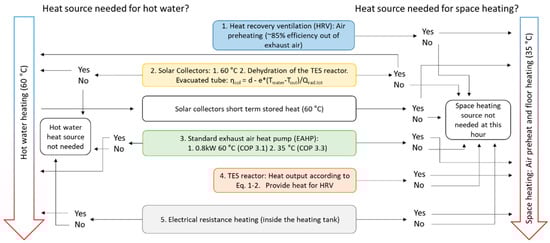
Figure 2.
The model algorithm and logic of taking heat sources into use for the case study building. Constants for evacuated tube solar collectors are d = 0.79 and e = 0.67.
The exhaust air heat pump (EAHP) either operates on full capacity or is switched off. The varying COP depending on output temperature is taken into account and the model checks for heating of tap water (60 °C, COP = 3.1) before checking the need for floor heating (35 °C, COP = 3.3) [23]. As shown in Figure 1, the tap water heat is provided by solar collectors and/or EAHP only. Additionally, ERH could be used for tap water heating although it is not needed in the model when considering that the EAHP heat effect is larger than the tap water heat requirement. Moreover, the possible condensation in the EAHP and chemisorption in the reactor are taken into account, which will lower the energy recovered in the heat recovery ventilation (HRV).
The TES reactors heat output of each reactor for a series of three is determined by three balance equations (Equations (1)–(3)) for operation at 90%, 70% and 50% RH determining the heat output (QRH90, QRH70, QRH50) as function of conversion grade quantified by mass ratio variable z = kgwater vapour/kgTES. This is done as to “dampen” the sudden heat release shock resulting from confronting dehydrated MgCO3·3H2O with high humidity air. The heat output QTES is calculated as a weighted average of the values obtained from the three equations.
The TES heat output is limited to 0.67 kW by the water vapour mass going through the ventilation system. The efficiency of the heat exchanger recovering the heat effect (QTES) is around 85%, resulting in 15% loss of the heat generated by the TES reactor. Presumably, the efficiency could be better, however in this simulation the idea was to add the TES system to available commercial solutions, where the maximum efficiency found for heat recovery ventilation was 85%. The equations were obtained from experimental data shown in Figure 3, partly presented in our earlier studies [2].
QRH90 = −9·10−10z4 + 5·10−7z3 − 9·10−5z2 + 0.0045z + 0.1797
R2 = 0.9642
R2 = 0.9642
QRH70 = 4·10−7z3 − 8·10−5z2 + 0.0014z + 0.2903
R2 = 0.9953
R2 = 0.9953
QRH50 = 0.0714e−0.039z
R2 = 0.8446
R2 = 0.8446
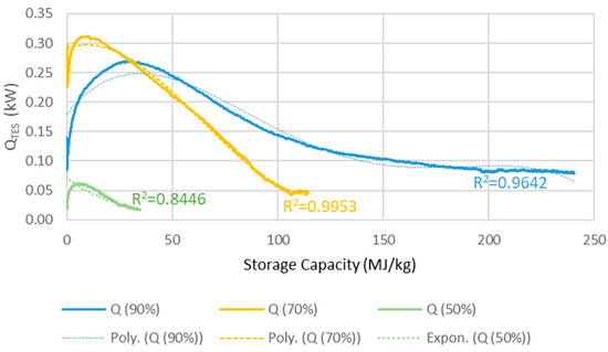
Figure 3.
The heat output, QTES (kW), versus the energy storage capacity (MJ/kg) used of the reactor in a 100 m2 house.
The effect of chemisorption of the water in the TES reactor decreasing the amount of water that will condense in the HRV was neglected for temperatures under 0 °C. (Typically, when the outdoor temperature of the gas entering the HRVs is above 0 °C, the TES is not in use.) This will prevent freezing of condensates in the heat exchanger, actually improving the commercial HRV system that will be more energy efficient because of this. Ice on the heat-exchanging surface decreases the heat transfers capacity and heat recovered from the ventilation air. Without TES, the model should include normal HRV operations such as shutting down or heating for the heat exchanging surfaces, avoiding a lowered efficiency.
The issue was resolved in the model by not allowing the HRV to subject the water to condensation at temperatures above 1 °C, which was accomplished by the TES system. Moreover, the output of the TES using three reactors in series was found to have a humidity around 0.2% RH and a dew point around −8 °C, which in southern Finland occurs only a few days per winter nowadays. This means that, using TES, most of the time no water would condense in the HRV and neglecting the condensation under 0 °C in the model will not affect the results. Thus, the TES more or less solves the freezing issue often encountered with HRV systems.
3.2. Serial Reactors
For various heat pump solutions, the COP values and heating capacity during colder periods are the most important calculated values for evaluating the system energy efficiency and performance. In Figure 4, the TES reactors’ impact on the heating systems was added to the COP value, as well as the total amount of hours for a given outdoor temperature. At outdoor temperatures between −10 and 0 °C, the COP improvement is very significant. In Helsinki (to which the temperature data applies), with a typical temperature distribution for coastal cities in southern Finland, the heating demand at outdoor temperatures between −10 and 0 °C is 3000–4000 h per year. As a large part of the heating time period, it matches well the temperature interval where the systems’ COP is highest, resulting in an improved energy efficiency.
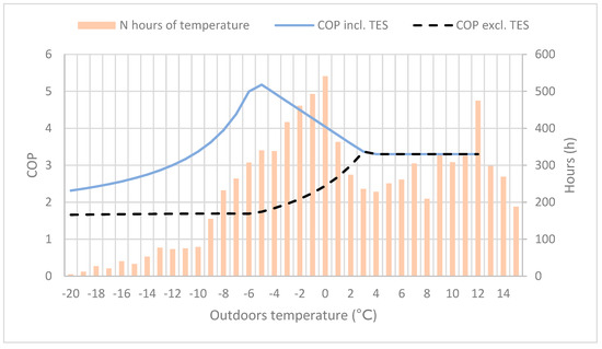
Figure 4.
The coefficient of performance (COP) with and without the thermal energy storage (TES) reactor, and the number of hours for varying outdoor temperature.
This decreases the electricity demand (as electrical resistance heating for EAHP and HRV are insufficient) during the colder periods, which on large scales could reduce the demand for emergency power plants based on fossil fuel during wintertime. However, to reduce (resistive) electricity use and peak load, the energy efficient heating capacity needs to match the demand during this time (such as −10 °C to 0 °C in southern Finland). As mentioned, the heat output of the TES reactor is limited by water vapour (specific humidity) present in the outlet air. This makes the dimensioning of the heating system for various types of house challenging.
In Figure 5, the house type (detached house) has an average heat loss of U = 0.13 (W/m2∙K) and requires electrical extra heating at outdoor temperatures below −6 °C. An apartment house would have a lower average U-value and presumably people living in a smaller space, resulting in more water vapour per m3 air. In the case of several levels, partly the heat from domestic water would be recovered, decreasing heat losses. However, in Figure 4 and Figure 5, the TES operates under optimal conditions which implies Tdew = Tout, and maximum output. The simulations in Section 4 will use actual weather data for an entire year from Kumpula, Helsinki (1.7.2018–30.6.2019), on the southern coast in Finland. The weather data used include hourly temperature, dew point and solar irradiation.
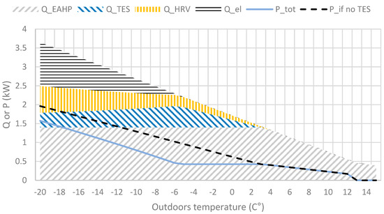
Figure 5.
Heat sources heat output (Q) and power (P) required with and without TES at various outdoor temperatures according to the concept. Water vapour pressure implies 100% RH at outdoor temperature and moisture generated in normal in-house living conditions (showering, plants, etc).
The decreasing maximum output of the TES as the temperature decreases is a result of the decreasing specific humidity (kg moisture/kg dry air) in the outdoor air, shown in Figure 5.
3.3. Reactor Configurations
The typical large heat output at a low hydration conversion levels and low kinetics at high conversion, shown in Figure 6, may be evened out by using a reactor divided into several units connected in series. The slower kinetics result in a decreased output air RH while another unit at a stage with lower conversion is capable to operate at lower humidity. This motivates the serial operation. This motivates the serial operation. For instance, in Figure 6 at 55 h after taking unit 1 into account, the RH between the units matches the values in scheme shown in Figure 7. In this case, unit 1 started at 0 h, unit 2 around 30 h and unit 3 after 50 h.
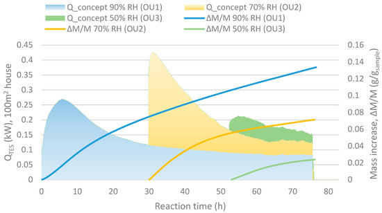
Figure 6.
Qconcept shows the heat output for a 100 m2 house with minimum ventilation and ∆M/M (g/gsample) stand for the mass increase compared to the initial mass (as dehydrated) of the sample.

Figure 7.
Schematic graph over the operating units (OU) connected in serial and the relative humidity (RH) of the inlets/outlets.
Interestingly, during the simulations the units behave very differently compared to the example illustrated by Figure 8, which is based on laboratory parameters (standard flow and limited by the humidity) and not actual heating requirements, as with the simulations. This is mainly due to much larger reactor volumes relative to the airflow (i.e., longer residence time for the gas inside the units) when compared to the experimental work (five units are used for the simulation for a whole year given here). The system simulation results show that several reactor units are necessary to reach a more stable maximum heat output. However, a single large unit reactor may also even out the reaction heat peak that results from a shortage of water vapour. It would lead to decreased chemisorption capacity and heat output at the end of the heating period or alternatively require a larger reactor (i.e., more material).
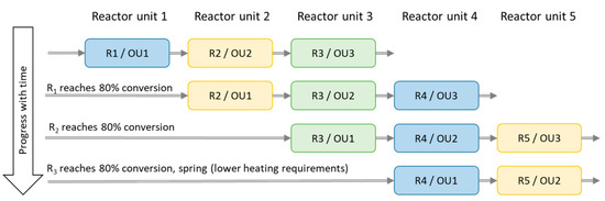
Figure 8.
Schematic graph over reactor unit (R) 1–5 acting as operating unit (OU) 1–3. The physical divisions of the reactor are named R 1–5, while the OU 1–3 are reactors operating in chronological order.
A set of simulations of three serial operating reactor units (out of a system composed of five reactor units in total) were used in order to increase the heat output and reactivity (decreasing the output air specific humidity). Algorithms choosing the best reactors appeared to prioritise the more converted (carbonate into its hydrate) unit as first reactor, leaving the least converted unit to the last. Thus, saving two reactor units to act as operating unit 2 and 3 until later and drier periods of the winter improved the results.
However, clearly better results were obtained with a more simple system and this was chosen for further study. The first four reactor units (R) acts as operating unit (OU) 1, and the two following (e.g., OU1 = R2, OU2 = R3, OU3 = R4) reactor units as OU2 and OU3 according to the scheme shown in Figure 8. Reactor unit 4 acts as OU1 and reactor unit 5 as OU2 during spring when the heating demand is smaller. Simulations with only one reactor unit were done for comparison.
4. Results and Discussion
To examine the applicability of the seasonal heat storage by chemisorption, simulations of the heating system were performed for a one-year period. The simulations start with July 2018 and end with June 2019, as the heat storage reactor is typically fully charged (which implies that the NQ crystal water is fully desorbed) during the summer. The apartment house considered has a floor area of 100 m2 according to the concept, however, the heat loss is calculated for a two-storey (narrow) terraced house, with insulation, in Finland according to building standards for new buildings, giving a low average thermal transmittance of U = 0.13 W/m2∙K (more details in Table 1 and Table 2).

Table 1.
House size and insulation data [24].
Table 2.
House heating and ventilations system data.
Shown in Figure 9, the heat output is much lower for the reactor unit (R) acting as operating unit (OU) 2 compared to 1 and 3 but leaving it out would only decrease the heat output. R4 starts acting as OU3 at the coldest time (around New Year’s Day) and is then at its chemically unconverted stage, which coincides with the driest (lowest outdoors air specific humidity, SH) time. It then requires a lower conversion for sufficient heat output, resulting, however, in a visible faster decreasing capacity compared to the others. This effect is also visible in Figure 10 and Figure 11 showing also that R3 gives a larger monthly output during December and January.
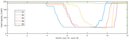
Figure 9.
Heat capacity of each reactor unit 12 months from July 2018 in the simulation with four reactor units in use (Sim4).
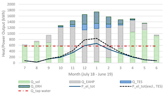
Figure 10.
The sum of heat output (in Sim4) for all heat sources and electricity consumption for each month.
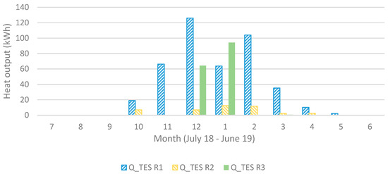
Figure 11.
Heat output (in Sim4) for each operating unit (1 to 3) for each month.
Clearly, the maximum heat output in January–February was considerably lower than when using the multi reactor system as described in Figure 8. This is normally the coldest time of the year, requiring the best heat output from the TES reactor as shown in Figure 10. Moreover, cold weather resulting in dry air will have the result that the used reactor unit conversion grade will be very low, as shown in Figure 3.
The usability/reactivity improvements by using multi-reactors were reviewed by simulating the concept using only one large reactor. The first simulation (Sim1) was with the same total reactor size (950 kWh/14.2 m3) as the optimal reactor size in multi-reactor systems. In the second simulation (Sim2) with one reactor, the conversion grade was matched to the best results (Sim4, four reactor units with up to three operating at one time), resulting in a reactor size of 750 kWh/11.2 m3.
As shown in Table 3, the multi-reactor system improves the available (sorption) heat by 26% with the same reactor size (same amount of TES material). More importantly, with similar hydration conversion levels, the multi-reactor system was able to increase available sorption capacity of composite material (from the EAHP outlet in such a way that it produces 49% more total heat and a larger reactor).
Table 3.
Reactor set up and result from the simulations.
A parallel reactor set-up (seen in other studies) would often give similar results to the one reactor set-up. However, it could possibly improve the results compared to the single reactor set-up, considering that a few of the low converted reactor units (in the beginning) would offer heat output peaks in the coldest time instead and not in the autumn (one reactor). Still, it would result in a half the heat output compared when the material has conversion grade around 0.33.
All the simulations were calculated with the same weather data and values for the HRV, solar panels and EAHP. The maximum heat output is limited by water vapour in the exhaust air, which is why the size of the TES unit is adjusted according to the maximum heat output and cannot fully replace the electrical resistance heating. The total annual domestic hot water usage is 6900 kWh and the space heating requirement is around 10,800 kWh of which 5200 kWh is recovered from the ventilation after the EAHP (total heat requirement is 17,700 kWh). However, a part of the exhaust heat is recovered in the EAHP (when it is in use) which has an annual effect of 6500 kWh (including recovered heat and compressor effect), following standard EAHP systems. These are typical values for a building in this region. The total electricity consumption in (Sim4) was 5127 kWh (3220 kWh ERH and 1906 kWh) and without the TES the total electricity consumption would be 5756 kWh (3849 kW ERH). When the system works in larger houses (apartment houses, etc.), the ERH would be relatively lower and the TES could compensate a larger part of the ERH, considering that larger houses have less wall surface m2 (and heat loss) per floor surface m2 and space m3.
The simulation model calculates improved system behaviour during sunny winter days (or in practice a system with a smart control system) by storage of the small portions of solar power available in January–February as shown in Figure 12. Shown in Figure 2, the TES systems model algorithm shuts down when the solar radiation is sufficient, which is not necessary in a case where the solar heat could be evened out (and short-time stored) during the day, decreasing heat requirements from electrical resistance.
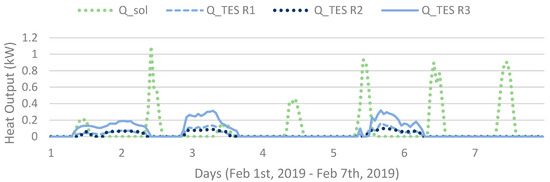
Figure 12.
Hourly heat output (in Sim4) of each operating unit (R1, R2, R3) and obtained heat of the solar collectors for a week.
New types of heat pumps using heat from both exhaust air and geothermal heat would give a more suitable match for the thermo-chemical energy storage. The maximum output for the heat pump is usually designed for temperatures around −5 °C and not 3 °C for the EAHP in this example. Another application possibility would be multi-storey buildings with even lower heat losses (less wall area per unit floor area).
Today, it is very common that large houses in cities use both EAHP and district heat instead of electrical heating during heat demand peaks. Absorption TES, as described here, would be an efficient measure to decrease the heat demand peaks that usually requires emergency heat plants (usually old fashioned/low efficiency plants using fossil fuels).
5. Conclusions
The novel concept for an integrated TES system as described and simulated in this paper could improve the performance and efficiency of a standard Nordic heating system in many aspects but the investment might be a risk:
- A significant part of the heat provided by electrical resistance at colder periods can be provided by the here described TES.
- The TES will decrease the freezing (in standard solutions) of condensed water during the use of heat recovery ventilation (HRV) as the TES increases the efficiency of the heat exchanger, more or less solving the freezing problem in commercial HRV systems.
- The investment might be high compared to the decreased electricity input requirements, but for an extended time of use it reduces the energy demand during winter when less renewable (solar) energy is available otherwise.
The water vapour in the exhaust air limits the heat output of the reactor. By improving the chemisorption process by operating serial reactor units properly operated with time, a larger storage capacity is possible. Using three reactors in series out of an arrangement that contains four reactors increases the available heat storage, improving the results by 49% compared to a one-reactor set-up. Moreover, it was shown that a serial arrangement is more favourable compared to a parallel one. Operating the reactors in series with reactors using magnesium carbonate hydrate and silica gel (or other types of sorbent decreasing heat output at higher conversion grades) clearly allows for a higher use of exhaust air water vapour that is otherwise disposed of into the environment.
Author Contributions
Conceptualization, R.E. and R.Z.; methodology, R.E. and R.Z.; software, R.E.; validation R.E. and R.Z.; formal analysis, R.E. and R.Z.; investigation, R.E. and R.Z.; resources, R.E. and R.Z.; data curation, R.E. and R.Z.; writing—original draft preparation, R.E.; writing—review and editing, R.Z. and R.E.; visualization, R.E.; supervision, R.Z.; project administration, R.E. and R.Z; funding acquisition, R.E. and R.Z. All authors have read and agree to the published version of the manuscript.
Funding
The authors want to acknowledge K.V. Lindholm Foundation, Erkki Paasikivi Foundation, Åbo Akademi Foundation for financial support for this work.
Conflicts of Interest
The authors declare no conflict of interest.
Abbreviations and Symbols
| CCS | Carbon capture and storage |
| CCSM | Carbon capture and storage by mineralisation |
| COP | Coefficient of performance |
| dH | Chemical capacity (kWh) |
| EAHP | Exhaust air heat pump |
| ERH | Electrical resistance heat |
| HRV | Heat recovery ventilation |
| ∆M/M | Mass increase per dehydrated reactor material (g/gsample) |
| NQ | Nesquehonite |
| OU(n) | Operating unit and its order number n |
| Qconcept | The heat output for a 100 m2 house with minimum ventilation following the concept |
| QRH90 | Reactor heat output as a function of z at 90% RH (kW) |
| QRH70 | Reactor heat output as a function of z at 70% RH (kW) |
| QRH50 | Reactor heat output as a function of z at 50% RH (kW) |
| QTES | Total reactor heat output from the TES reactor (kW) |
| R(n) | Reactor unit and its order number n |
| RH | Relative humidity |
| SG | Silica gel |
| SH | Specific humidity (kg moisture/kg dry air) |
| Sim(n) | Simulation number |
| STESTdew | Seasonal thermal energy storageDewpoint temperature (°C) |
| Tsolcol | Working temperature of solar collectors in the model |
| TES | Thermal energy storage |
| z | Mass increase per dehydrated reactor material (kgwater vapour/kgTES) |
References
- Bauer, D.; Marx, R.; Nußbicker-Lux, J.; Ochs, F.; Heidemann, W.; Müller-Steinhagen, H. German central solar heating plants with seasonal heat storage. Sol. Energy 2010, 84, 612–623. [Google Scholar] [CrossRef]
- Erlund, R.; Zevenhoven, R. Thermal energy storage (TES) capacity of a lab-scale magnesium hydrocarbonates / silica gel system. J. Energy Storage 2019, 25, 100907. [Google Scholar] [CrossRef]
- Zevenhoven, R.; Slotte, M.; Koivisto, E.; Erlund, R. Serpentine carbonation process routs using ammonium sulphate and integration in industry. Energy Technol. 2017, 5, 945–954. [Google Scholar] [CrossRef]
- Erlund, R.; Koivisto, E.; Fagerholm, M.; Zevenhoven, R. Extraction of magnesium from four Finnish magnesium silicate rocks for CO2 mineralisation—Part 2: Aqueous solution extraction. Hydrometallurgy 2016, 166, 229–236. [Google Scholar] [CrossRef]
- Koivisto, E.; Erlund, R.; Fagerholm, M.; Zevenhoven, R. Extraction of magnesium from four Finnish magnesium silicate rocks for CO2 mineralisation—Part 1: Thermal solid/solid extraction. Hydrometallurgy 2016, 166, 222–228. [Google Scholar] [CrossRef]
- Zevenhoven, R.; Slotte, M.; Åbacka, J.; Highfield, J. A comparison of CO2 mineral carbonation processes involving a dry or wet carbonation step. Energy 2016, 177, 604–611. [Google Scholar] [CrossRef]
- Erlund, R.; Zevenhoven, R. Thermal storage of (solar) energy by sorption of water in magnesium (hydro) carbonates. Int. J. Thermodyn. 2017, 20, 102–109. [Google Scholar] [CrossRef]
- Erlund, R.; Zevenhoven, R. Hydration of magnesium carbonate in a thermal energy storage process and its heating application design. Energies 2018, 11, 170. [Google Scholar] [CrossRef]
- Zondag, H.; Kikkert, B.; Smeding, S.; De Boer, R.; Bakker, M. Prototype thermochemical heat storage with open reactor system. Appl. Energy 2013, 109, 360–365. [Google Scholar] [CrossRef]
- Lim, K.; Che, J.; Lee, J. Experimental study on adsorption characteristics of a water and silica-gel based thermal energy storage (TES) system. Appl. Therm. Eng. 2017, 110, 80–88. [Google Scholar] [CrossRef]
- Engel, G.; Asenbeck, S.; Köll, R.; Kerskes, H.; Wagner, W.; van Helden, W. Simulation of a seasonal, solar-driven sorption storage heating system. J. Energy Storage 2017, 14, 40–47. [Google Scholar] [CrossRef]
- Elmegaard, B.; Schmidt Ommen, T.; Markussen, M.; Iversen, J. Integration of space heating and hot water supply in low temperature district heating. Energy Build. 2016, 124, 255–264. [Google Scholar] [CrossRef]
- Whiting, G.; Grondin, D.; Bennici, S.; Auroux, A. Heats of water sorption studies on zeolite–MgSO4 composites as potential thermochemical heat storage materials. Sol. Energy Mater. Sol. Cells 2013, 112, 112–119. [Google Scholar] [CrossRef]
- Hongois, S.; Kuznik, F.; Stevens, P.; Roux., J.-J. Development and characterization of a new MgSO4-zeolite composite for long-term thermal energy storage. Sol. Energy Mater. Sol. Cells 2011, 1831–1837. [Google Scholar] [CrossRef]
- Edem N’Tsoukpoe, K.; Liu, H.; Le Pierrès, N.; Luo, L. A review on long-term sorption solar energy storage. Renew. Sustain. Energy Rev. 2009, 13, 2385–2396. [Google Scholar]
- Scapino, L.; Zondag, H.A.; Van Baelac, J.; Diriken, J.; Rindt, C.C.M. Sorption heat storage for long-term low-temperature applications: A review on the advancements at material and prototype scale. Appl. Energy 2017, 190, 920–948. [Google Scholar] [CrossRef]
- Tahat, M.A. Heat-pump/energy-store using silica gel and water as a working pair. Appl. Energy 2001, 69, 19–27. [Google Scholar] [CrossRef]
- HSC Chemistry; Version 8.1.1; Reaction Equations; Outotec: Pori, Finland, 2014.
- Hollingbery, L.A.; Hull, T.R. The fire retardant behaviour of huntite and hydromagnesite—A review. Polym. Degrad. Stab. 2010, 95, 2213–2225. [Google Scholar] [CrossRef]
- Yan, T.; Wang, R.Z.; Li, T.X.; Wang, L.W.; Freda, I.T. A review of promising candidate reactions for chemical heat storage. Renew. Sustain. Energy Rev. 2015, 43, 13–31. [Google Scholar] [CrossRef]
- Whiting, G.; Grondin, D.; Stosic, D.; Bennici, S.; Auroux, A. Zeolite–MgCl2 composites as potential long-term heat storage materials: Influence of zeolite properties on heats of water sorption. Sol. Energy Mater. Sol. Cells 2014, 128, 289–295. [Google Scholar] [CrossRef]
- Fracastoro, G.V.; Serraino, M. Energy analyses of buildings equipped with exhaust air heat pumps (EAHP). Energy Build. 2010, 42, 1283–1289. [Google Scholar] [CrossRef]
- Mikola, A.; Kõiv, T.-A. The efficiency analysis of the exhaust air heat pump system. Engineering (Estonia) 2014, 6, 1037–1045. [Google Scholar] [CrossRef]
- Rakentaja.fi. The U-values of Building Segments (in Finnish: Rakennusosien U-arvot). Available online: https://www.rakentaja.fi/artikkelit/9222/rakennusosien_u_arvot.htm (accessed on 4 June 2020).


© 2020 by the authors. Licensee MDPI, Basel, Switzerland. This article is an open access article distributed under the terms and conditions of the Creative Commons Attribution (CC BY) license (http://creativecommons.org/licenses/by/4.0/).