Article

Effect of Conical Strip Inserts and ZrO2/DI-Water Nanofluid on Heat Transfer Augmentation: An Experimental Study

by
Mohamed Iqbal Shajahan
1,*,
Jee Joe Michael
2,
M. Arulprakasajothi
1,
Sivan Suresh
3,
Emad Abouel Nasr
4,5 and
H. M. A. Hussein
5
1
Department of Mechanical Engineering, Vel Tech Rangarajan Dr. Sagunthala R&D Institute of Science and Technology, Avadi, Chennai 600062, India
2
Department of Energy Science and Engineering, Indian Institute of Technology Bombay, Mumbai 400076, India
3
Department of Mechanical Engineering, National Institute of Technology Tiruchirappalli, Tiruchirappalli 620015, India
4
Department of Industrial Engineering, Faculty of Engineering, King Saud University, Riyadh 11421, Saudi Arabia
5
Department of Mechanical Engineering, Faculty of Engineering, Helwan University, Cairo 11732, Egypt
*
Author to whom correspondence should be addressed.
Energies 2020, 13(17), 4554; https://doi.org/10.3390/en13174554
Submission received: 21 July 2020 / Revised: 25 August 2020 / Accepted: 29 August 2020 / Published: 2 September 2020

Abstract

:
There is a significant enhancement of the heat transfer rate with the usage of nanofluid. This article describes a study of the combination of using nanofluid with inserts, which has proved itself in attaining higher benefits in a heat exchanger, such as the radiator in automobiles, industries, etc. Nanofluids are emerging as alternative fluids for heat transfer applications due to enhanced thermal properties. In this paper, the thermal hydraulic performance of ZrO2, awater-based nanofluid with various volume concentrations of 0.1%, 0.25%, and 0.5%, and staggered conical strip inserts with three different twist ratios of 2.5, 3.5, and 4.5 in forward and backward flow patterns were experimentally tested under a fully developed laminar flow regime of 0–50 lphthrough a horizontal test pipe section with a length of 1 m with a constant wall heat flux of 280 W as the input boundary condition. The temperatures at equidistant position and across the test section were measured using K-type thermocouples. The pressure drop across the test section was measured using a U-tube manometer. The observed results showed that the use of staggered conical strip inserts improved the heat transfer rates up to that of 130.5%, 102.7%, and 64.52% in the forward arrangement, and similarly 145.03%, 116.57%, and 80.92% in the backward arrangement with the twist ratios of 2.5, 3.5, and 4.5 at the 0.5% volume concentration of ZrO2 nanofluid. It was also seen that the improvement in heat transfer was comparatively lower for the other two volume concentrations considered in this study. The twist ratio generates more swirl flow, disrupting the thermal hydraulic boundary layer. Nanofluids with a higher volume concentration lead to higher heat transfer due to higher effective thermal conductivity of the prepared nanofluid. The thermal performance factor (TPF) with conical strip inserts at all volume concentrations of nanofluids was perceived as greater than 1. A sizable thermal performance ratio of 1.62 was obtained for the backward-arranged conical strip insert with 2.5 as the twist ratio and a volume concentration of 0.5% ZrO2/deionized water nanofluid. Correlations were developed for the Nusselt number and friction factor based on the obtained experimental data with the help of regression analysis.

1. Introduction

There are several heat transfer augmentation techniques that were developed to achieve enhanced heat transfer rate and compact design in various heat exchanger applications for both engineering and industrial purposes, such as manufacturing systems, air-conditioning systems, solar heating systems, refrigeration systems, microelectronics, etc., to attain material, energy, and cost savings. There are umpteen numbers of investigations that have been carried out numerically and experimentally on the heat transfer augmentation of commonly working fluids, such as water, oil, ethylene glycol, etc. Suganthi and Rajan [1] suggested guidelines for selecting appropriate nanofluids for enhancement of heat transfer, which include the selection of nanomaterials having higher values of specific heat, thermal conductivity, and surface area; and lower values of the density, aspect ratio, and viscosity. There are several researchers who have reported on nanofluid, which influences augmented heat transfer in a forced convection system. The experimental studies revealed that the intensified thermal conductivity and viscosity of nanofluids depend on the shape, size, and volume concentrations of nanoparticles [2,3,4]. Zeta potential evidently proved the stability of nanofluid [5]. On the other hand, many experimental investigations on water-based nanofluids, such as graphene/water [6], silica/water [7], TiO2/water [8], and Al2O3/water [9], promoted increased heat transfer in terms of the Nusselt number and without much penalty on the pumping power.
The performance of nanofluids can be ascertained by incorporating swirl generators in the flow passage to promote more convective heat transfer; these swirl generators may be in the arrangement of a helical coil [10], helical tape [11], helical screw tape [12], wire coil [13,14,15,16], twisted tape [17,18,19,20,21,22], and conical strip [23]. On the contrary, the friction factor developed due to the pressure drop. The effectiveness, which is ensured by both the swirl generator insertion and nanofluids conformed by the thermal performance factor, is normally more than the unity [24].
Bahiraei et al. [25] conducted an experimental work to obtain the thermo-physical properties and efficiency of non-Newtonian nanofluid containing titanium di-oxide nanoparticles in a disorganized geometry. During this study, it was found that the convective heat transfer coefficient was disordered and had a periodic behavior. Li et al. [26] conducted an experiment on convective heat transfer and pressure drop parameters of ZnO2/EG-H2O nanofluids in transition flow. They found that at 2.5 wt.%, the nanofluids had increased the convective heat transfer coefficient by 30% compared to that of water. However, for 5 wt.% and above, the heat transfer rate decreased. Amani et al. [27] intended to determine the effect of the heterogeneous distribution of nanofluids containing SiO2. The results revealed that the Peclet number (Pe) had a greater contribution to the heterogeneity of the nanofluids. Babu et al. [28] intimated that hybrid nanofluids may show improved thermal conductivity and rheological properties because of a synergistic effect. Kumar and Arasu [29] reviewed the preparation, properties, and stability of hybrid nanofluids. Das [30] suggested various requirements that are essential to developing hybrid nanofluids for improving thermal conductivity.
Pal and Saha [31] revealed that oblique teeth, twisted tapes, and spiral ribs exhibited better thermal performance for fluid flow compared with that of the other inserts. Man et al. [32] proved that the convective heat transfer coefficient (h) of flow in a tube (length = 2400 mm) containing an alternation of clockwise- and counter-clockwise-twisted (ACCT) tape inserts was enhanced to 1.42 times compared to using typical twisted (TT) tape inserts in a double-pipe heat exchanger in a turbulent flow regime. A similar study was conducted using a bidirectional conical strip insert and the results targeted that cold and hot fluidsin the core and periphery zone are expeditiously exchanged, causing multiple longitudinal turbulence downstream [33]. The turbulent flow behavior in a cylindrical pipe equipped with twisted-type conical strip inserts showed that the Nusselt number and friction factor increase with increasing the slant angle, reducing the pitch and twist angle [34]. In laminar flow, a wider strip size, narrow strip-wall gap, and smaller strip pitch can effectively enhance the heat transfer rate but also increase the flow blockage [35].
Chopkar [36] experimentally investigated the ZrO2/water and ZrO2/EG nanofluid thermo-physical properties, and found that the significant enhancement on thermal conductivity for both the fluids in sequence heat transfer intensified. Mohammed et al. [37] indicated that SiO2nanofluiddeveloped a higher Nusselt number value when compared to other nanofluids, such as Al2O3, CuO, and ZnO2 with louvered strip inserts. Aghayari et al. [38] proved that the mixing of Fe2O3 nanoparticles in water resulted in a 130% increase in the heat transfer performance when the perforated twisted tape twist ratio was 2.5 and nanoparticle volume concentration was 0.2% in a double-pipe heat exchanger.
It is clearly observed that from the previous literature on numerical and experimental investigations by many researchers, for an evaluation of heat transfer enhancement by using conventional inserts and working fluid, these need to be replaced by other kinds of inserts with higher thermal conductivity fluid. To further increase the thermal performance of radiators in automobiles and thermal industrial applications, more research is required to optimize this combination to attain an improved heat transfer rate with a reduction in the size of the heat exchangers. The present investigation investigated novel staggered-conical strip inserts and ZrO2/DI water nanofluid, which were not recorded previously. An experimental study was carried out for three various twist ratios of conical inserts (Y = 2.5, Y = 3.5, and Y = 4.5) in forward and backward flow patterns employed in a uniformly heated pipe, in addition to ZrO2/DI water nanofluids at three different volume concentrations (0.1, 0.2, and 0.5 vol.%) under laminar flow. This work further calculated the heat transfer enhancement andpressure drop intensification for the inserts and nanofluids compared with the plain tube, based on the Nusselt number and friction factor parameters, and the thermal performance factor intended to analyze the overall system performance.

2. Methodology

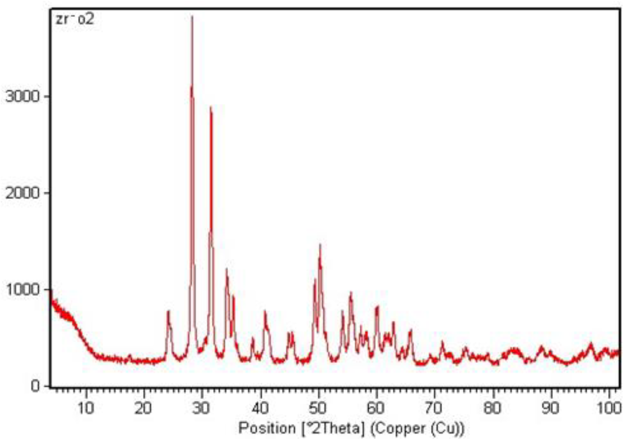
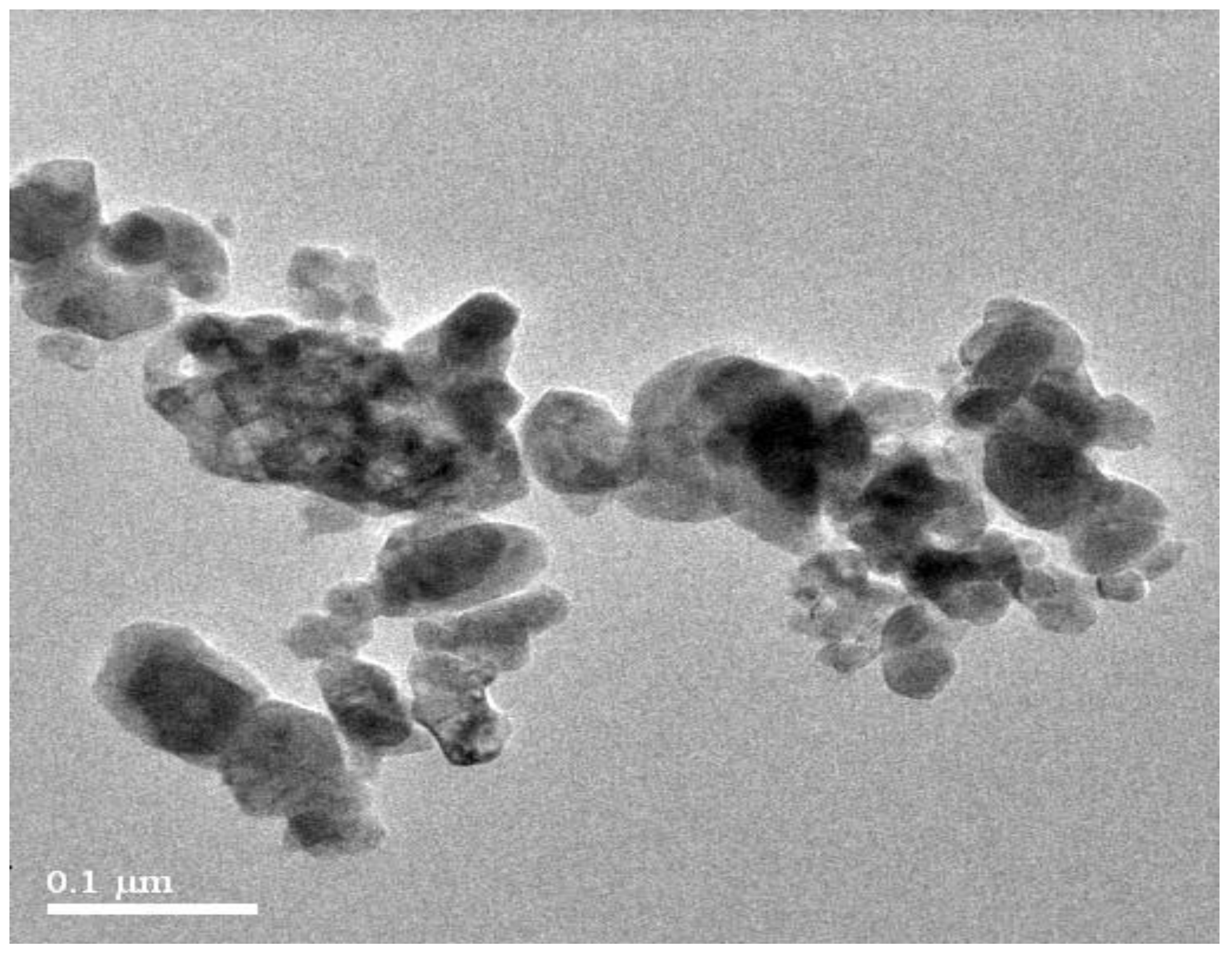
2.1. Analysis Techniques

The powder X-ray diffraction (XRD) analysis revealed the crystalline structure and purity of the nanoparticles. The ZrO2 nanoparticles were tested on an advanced X-ray diffractometer (Bruker AXS D8) by Cu-k1 radiation and the XRD pattern shown in Figure 1 confirms it as ZrO2 material. In general, scanning electron microscope (SEM) is employed to learn about the size and shape of the nanoparticles. The scanning electron microscope (Quanta FEG 200-High Resolution) was pivotal to conclude that ZrO2 is spherical in shape in nature as shown in Figure 2.

2.2. Preparation of Nanofluids

The zirconium dioxide/zirconia (ZrO2) from Alfa Aesar (Ward Hill, MA, USA) nanoparticles has an average size of 25 nm, and deionized water (DI) from Chandanmal & Co (Tamil Nadu, India), which were used in the preparation of ZrO2 nanofluid. Since it is a refractory material with reasonable thermophysical property increment shown by test results, this motivated the investigation of this present study. Their properties are given below in Table 1. The ZrO2 nanofluid preparation involved dispersing ZrO2 nanoparticles in deionized (DI) water with a surfactant yttrium oxide (Y2O3) [36]. The surfactant was added to increase the dispersion stability of the ZrO2 nanoparticles in water. There are about three different volume fractions, such as 0.1, 0.25, and 0.5 vol.%, that were used to prepare the nanofluids, which required a volume-equivalent weight of nanopowder dispersedinto the deionized water in a vessel simultaneously stirred with the magnetic stirrer for an hour. Then, it was sonicated using the ultra-sonicator for the proper suspension of nanoparticles up to 3 h [39]. This process ensured a uniform distribution as well as the dispersion stability of the ZrO2 nanoparticles in water. The transmission electron microscopy (TEM) is an advanced nano-characterization method to explore the distribution of nanoparticles in the fluid medium. The ZrO2 nanoparticles form a nanoclustering as shown in Figure 3. Thermal conductivity (k) and dynamic viscosity (µ) were measured by a KD2-pro and Brookfield Viscometer, respectively. The measured values of dynamic viscosity (µ) and thermal conductivity (k) of ZrO2/DI water were discussed in a previous investigation [40], and the density (ρ) and specific heat (cp) values were estimated for the range of concentrations using the correlations [41,42] and expressed by Equations (1) and (2),respectively. The estimated Prandtl number is also given in the Table 1:
ρ n f = φ ρ n p + ( 1 φ ) · ρ b f ,
( ρ c p ) n f = φ ( ρ c p ) n p + ( 1 φ ) ( ρ c p ) b f .

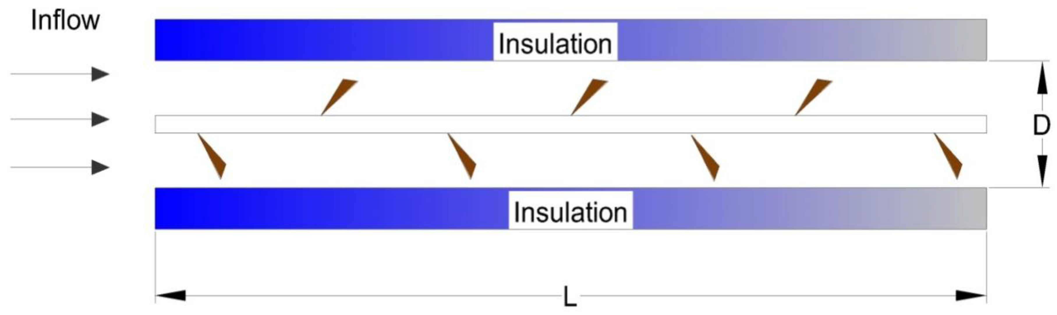
2.3. Fabrication of Staggered Conical Strip Inserts

The geometrical metric of the conical strip insert is shown in Figure 4. The conical strip inserts with three different twist ratios (Y) were fabricated, namely staggered with forward and backward arrangements. A core rod of a 1000-mm length was welded with conical strip inserts of a 0.5-mm thickness placed equidistantly and alternatively at a distance of 25 mm. Then, the same procedure was also followed for the 35- and 45-mm pitches with a slant angle of α = 45°.

2.4. Twist Ratio (Y)

The ratio between the pitch (P) length to the diameter (Di) of the test section (10 mm) is called the twist ratio (Y = P/Di), as shown in Table 2 with three various twist ratios for non-staggered conical strip inserts. Figure 5 shows the photographic view of three twist ratios of the staggered conical strip inserts, namely Y = 2.5, 3.5, and 4.5, respectively. Figure 6 shows the schematic arrangement of the forward and backward arrangement for three different twist ratios [43,44].

3. Experimentation

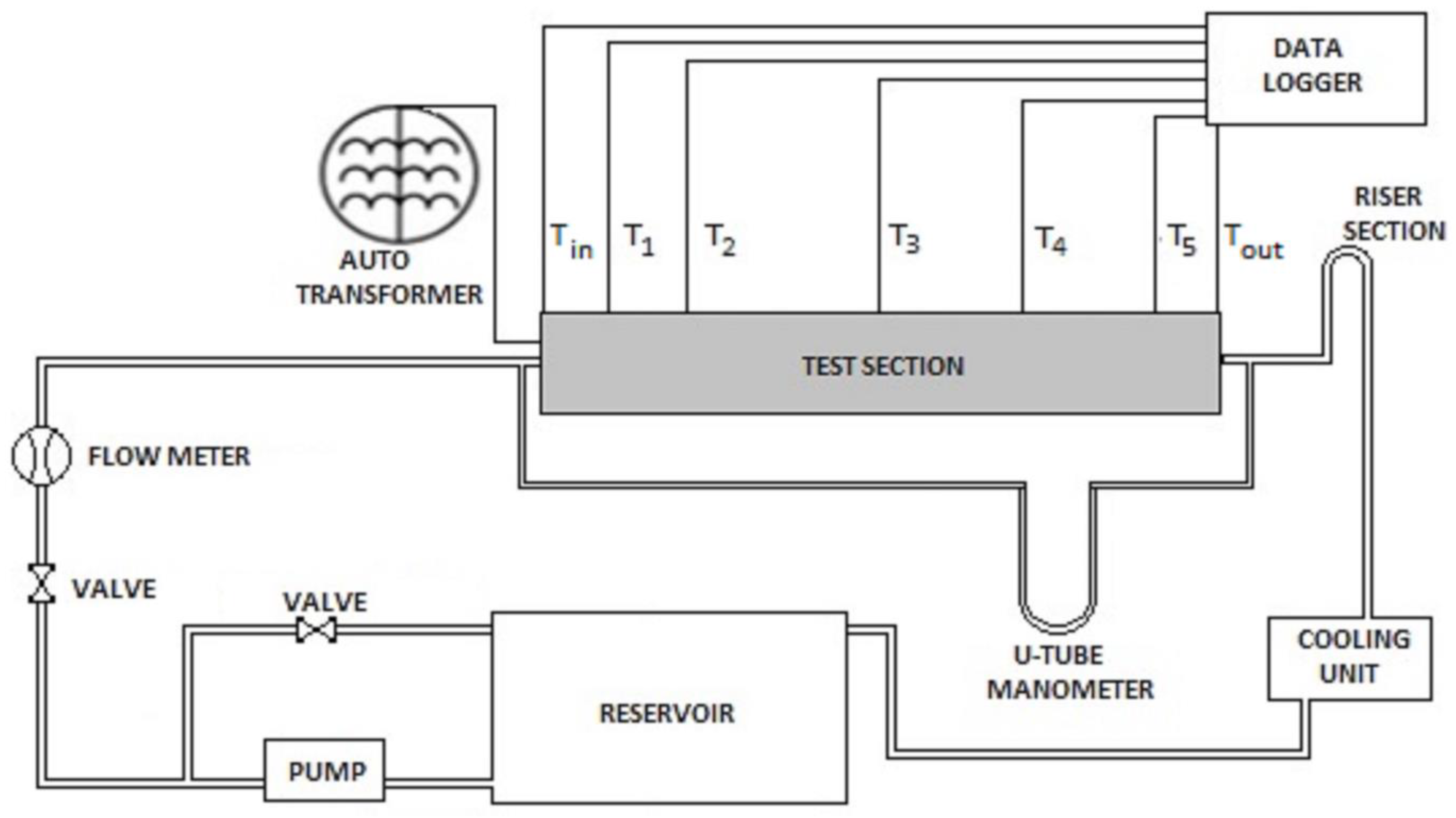
3.1. Details of the Experimental Facility

The experimental set up of the present investigation consisted of an entrance section, riser section, cylindrical pipe (test section), cooling unit, pump, control valve, rotameter, heating arrangement, and operating panel; a schematic arrangement of the experimental test facility is shown in Figure 7. A straight cylindrical tube having a length of 1 m, with an inner diameter of 0.010 m and an outer diameter of 0.012m, was used as the test section, made up of copper. It was wounded with a nichrome heating coil, having a heating capacity of 1000W.The heater was thermally insulated with glass wool to prevent heat dissipation to the surroundings. The heater was connected by an auto transformer for varying of the input power. The entrance section was provided to obtain fully developed flow. The riser section was fixed to achieve a uniform flow. The positions of thermocouples (K-type, accuracy 0.1°C) was used to measure the outer periphery of the test section temperatures, which were located axially at a distance of about 0.15, 0.30, 0.60, 0.75, and 0.90 m, respectively, from the inlet of the test section. Another two thermocouples slotted at a distance of 15 mm of each side of the test section were used to measure the inlet and outlet working fluid temperatures. Measured temperatures were trapped by the data acquisition system through visual studio software and stored in a computer. The pressure drop between the inlet and exit of the test section was measured using a U-tube manometer, and a cooling unit was provided to achieve cooling of the working fluid. A reservoir to collect the working fluid, a rotameter capacity of 0–60 lph provided to measure the volume flow rate, and a control valve for controlling the flow rate were also used as per the requirements. Many researchers reported similar kinds of forced convection experimental set-ups for various nanofluids and inserts in the literature [45,46,47].

3.2. Experimental Procedure

The fluid was pumped by a centrifugal pump and regulated by the control valve, and the flow rate was between 0 and 50 lph for achieving the laminar flow condition. The fluid directed to the calming section gained fully developed flow, and consequently, fluid passed through the test section was subjected to a constant wall heat flux [48]. Then, the working fluid was cooled in the cooling unit, and the pressure difference in the fluid was recorded using a U-tube manometer in terms of the mercury column. This cycle was repeated for experimental runs using the plain tube, staggered conical stripsfor both the forward and backward directions with different twist ratios (Y = 2.5, 3.5, and 4.5), for DI water, and for various fractions of ZrO2/DI water nanofluid (0.1, 0.25, and 0.5 vol.%).

3.3. Data Processing

Heat supplied to the nichrome winding was calculated as:
Q 1 = V I
Heat extracted by the fluid in the test section was estimated as:
Q 2 = m c p ( T o u t T i n )
The heat flux was evaluated by the following equations:
Q = Q 1 + Q 2 2
q = Q π D L .
The average convective heat transfer coefficient is given by the following equation:
h = q ( T w T f ) .
The heat transfer coefficient was involved to estimate the average Nusselt number (Nu):
N u = h D i k .
The pressure drop (∆p) between the inlet and exit of the test section under isothermal conditions was used to determine the friction factor (f) using the following equation:
f = Δ p 1 2 ρ v 2 D L .
In the present experimental investigation, the thermal performance factor evaluation method for the constant pumping power was adopted by the expression of Usui et al.’s [49] model under laminar flow:
Thermal performance factor,
T P F = ( N u N u p ) ( f f p ) 0.166 .

3.4. Uncertainty Analysis

The uncertainties of various physical quantities derived from the experimental data will influence the results of the Nusselt number (Nu), Reynolds number (Re), and friction factor (f).The uncertainty was calculated based on the procedure introduced by Kline-McClintock [50]. For this, an estimation of the uncertainty for the instruments of this experimental facility is presented in Table 3. Eeach parameter’s possible error involved was taken into consideration and evaluated carefully [51].
The Nusselt number uncertainty was estimated by the following equations:
N u = h D i k = V I π L ( T w T f ) k ,
Δ N u N u = [ ( Δ V V ) 2 + ( Δ I I ) 2 + ( Δ L L ) 2 + ( Δ T w T w ) 2 + ( Δ T f T f ) 2 ] 0.5 .
Reynolds number uncertainty was estimated by the following equations:
Re = 4 m π D μ ,
Δ Re Re = [ ( Δ m m ) 2 + ( Δ d d ) 2 ] 0.5   .
The Friction factor uncertainty was calculated by the following equations:
f = 1 2 [ Δ P L ] [ ρ D i 3 R e 2 μ 2 ] ,
Δ f f = [ ( Δ ( Δ p ) Δ p ) 2 + ( Δ L L ) 2 + ( 3 Δ d i d i ) 2 + ( 2 Δ Re Re ) 2 ] 0.5 .
The maximum uncertainties estimated in the Reynolds number (Re), Nusselt number (Nu), and friction factor (f) were found to be ±0.58%, ±2.78%, and ±3.2%, respectively.

4. Results and Discussion

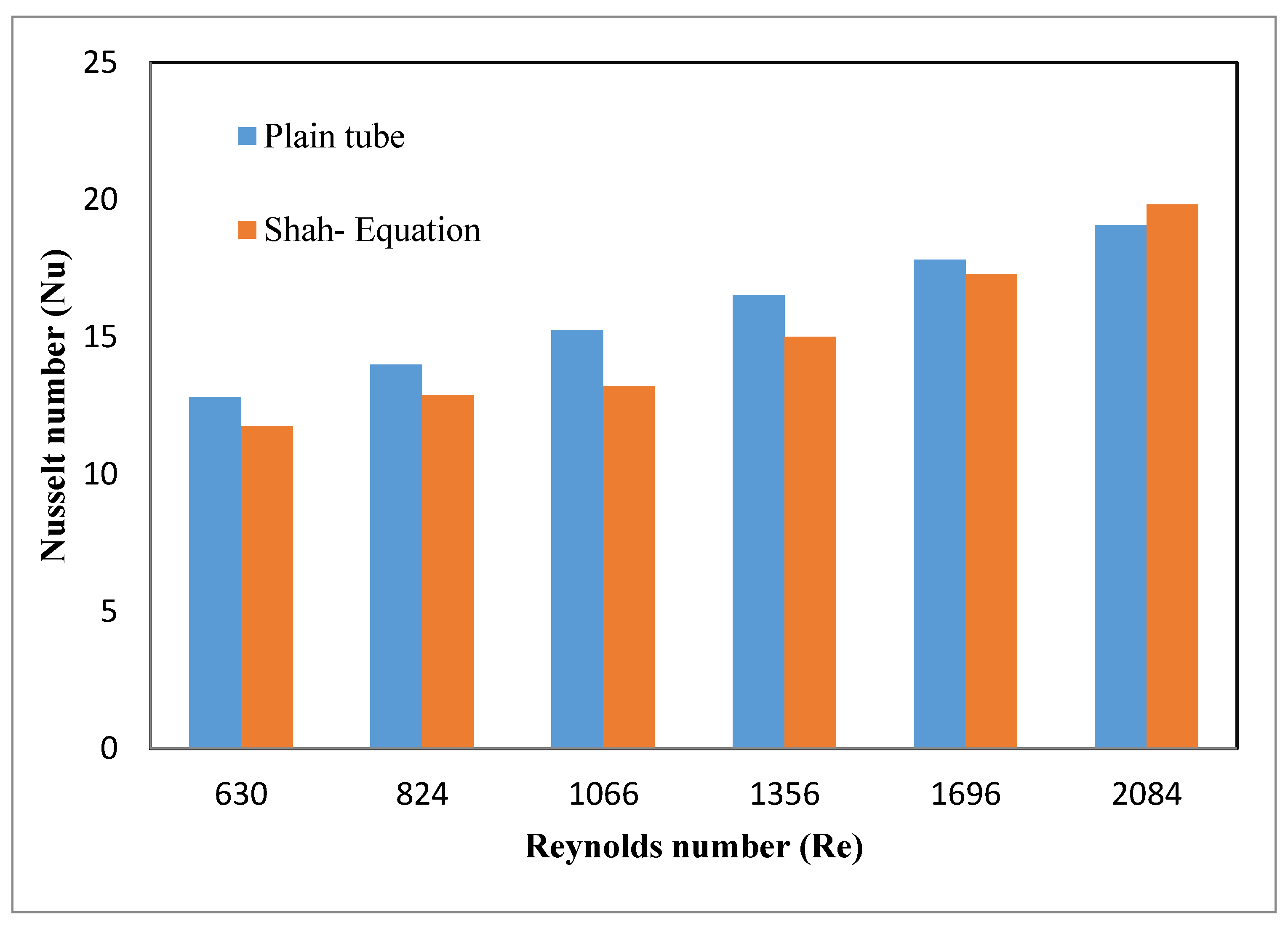
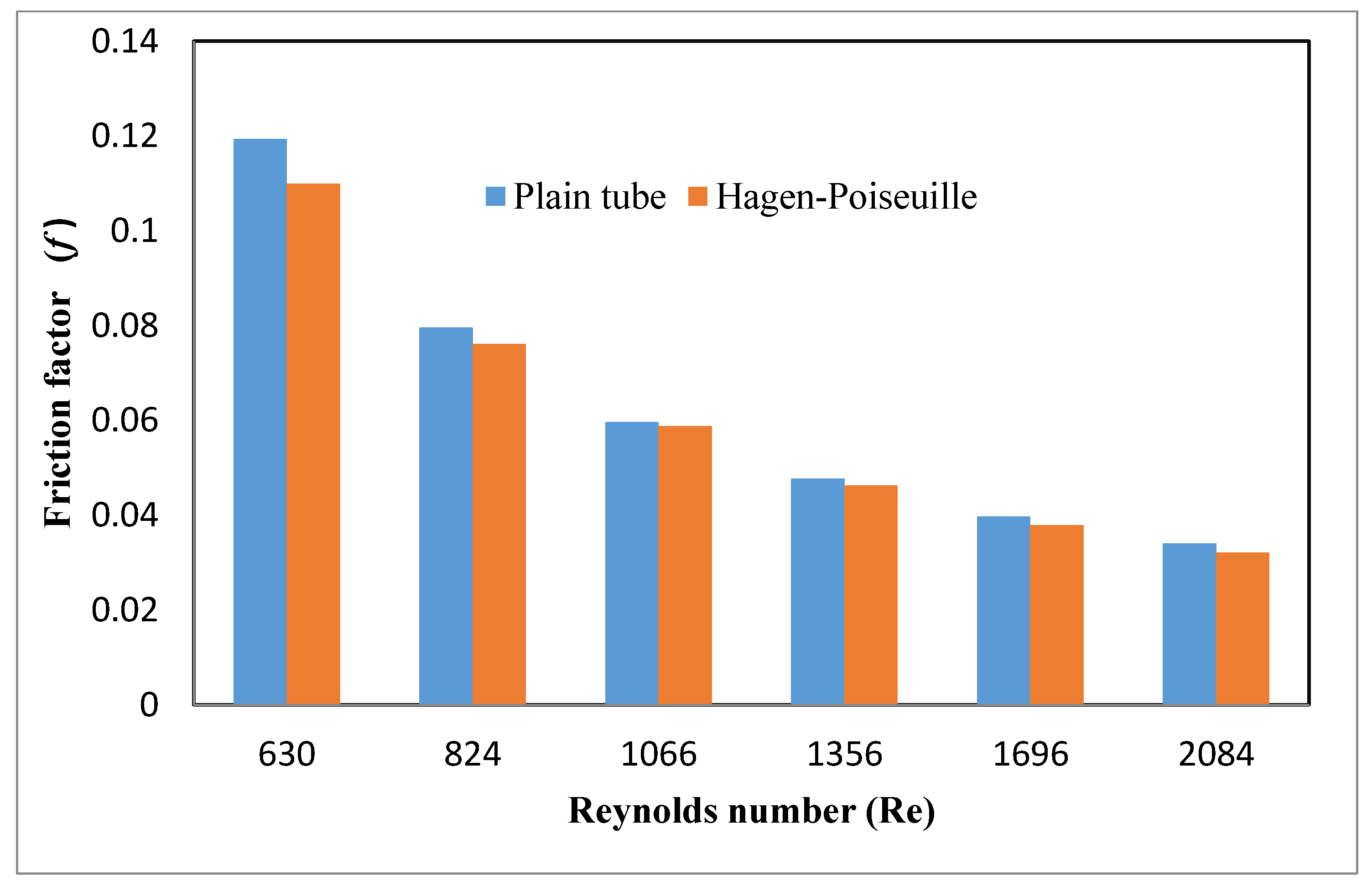
4.1. Plain Tube Data for Validation Study under Laminar Flow

The experimental results of the convective heat transfer and pressure drop of the uniformly heated pipe with working fluid DI water under laminar flow were validated in terms of the Nusselt number and friction factor in order to assess the reliability of the experimental set-up. These parameters were compared to the standard correlation of Shah and Hagen–Poiseuille under the laminar flow regime in a plain tube.
The Shah [52] correlation is presented by Equations (17) and (18):
N u = 1.953 ( Re Pr d x ) ( 1 3 ) f o r ( Re Pr d x ) 33.33   ,
N u   =   4.364   +   0.0722 ( Re Pr d x ) f o r ( Re Pr d x ) <   33.33   .
The Hagen–Poiseuille correlation was presented by Equation (19):
f = 64 Re   .
Figure 8 depicts the graph showing the Nusselt number varying with the Reynolds number for the actual and calculated values using Shah Equations (17) and (18). It could be seen that the experimental values of the Nusselt number had deviations of ±8.9% compared to that of the theoretical values obtained by Shah equations as shown in Figure 8. This exhibited that the experimental data have good agreement with the correlated values. Figure 9 depicts the variation of the friction factor with the Reynolds number for the experimental values and predictable values using the Hagen–Poiseuille correlation presented by Equation (19). It can be observed that the obtained experimental friction factor values compared with that of the values obtained by theoretical values showed a discrepancy of ±8.4%. Hence, it proved the experimental facility was good for further experimentation.

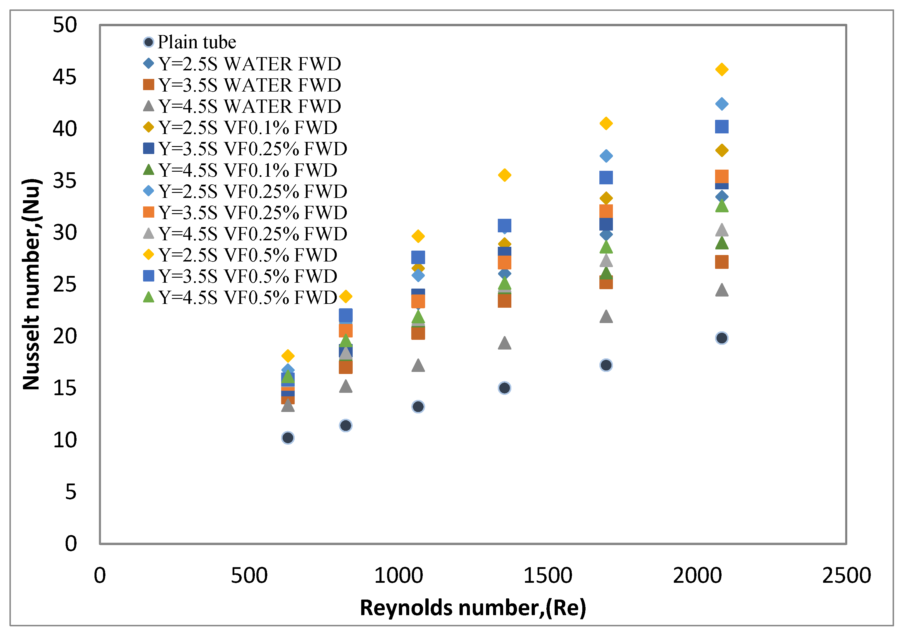
4.2. The Effect of the Staggered Conical Strip Insert with Both Forward and Backward Direction and Nanofluid on Heat Transfer

The variations of the Nusselt number with the Reynolds number for the test section fittedwitha staggered conical strip insert in the forward direction of three different twist ratios (Y = 2.5, 3.5, 4.5) and with 0.1, 0.25, and 0.5 vol.% fractions are shown in Figure 10. The graph illustrates that the Nusselt number for the Reynolds number ranging between 600 and 2100 was higher for low twist ratios. The Nusselt number increased with an increase in the nanofluid volume fraction as well as the Reynolds number. These behaviors were due to continuous swirl flow along the twist insert, resulting in an increase in the velocity and causing a disruption in the boundary layer thickness. This swirl flow enhanced the turbulence intensity, leading to an intense fluid mixing, and thereby attaining additional convective heat transfer augmentation compared to in the plain tube. The path of fluid flow along the conical strip was generated in a swaying manner, with further continuous whirling motion lasting till the end of the test section. The Nusselt number enhancement with different twist ratios of Y = 2.5, 3.5, and 4.5 for DI water was 68.74%, 37.01%, and 23.55%. These values were more than the values obtained for the plain tube, which revealed that a reduction in the twist ratio increased the effectiveness for the staggered conical strip insert in the forward arrangement. The extreme valuation of the Nusselt number was gained for the twist ratio Y = 2.5 using 0.5 vol.% of nanofluid and the average increase in the Nusselt number was divulged to be 130.55% compared to the value obtained for the plain tube. The heat transfer augmentation due to the influence of the ZrO2 nanoparticle was owing to the suspension of the nanoparticles in the fluid, which caused particle migration, chaotic movement of the nanoparticles, and clustering mechanisms escalated the heat transfer.
The results depicted from Figure 11 showed that the staggered conical strip inserts with a backward direction fitted in the uniformly heated pipe obtained bountiful heat transfer enhancement in terms of the Nusselt number stretched with sets of the Reynolds number for three different twist ratios using deionized water and ZrO2/deionized water nanofluid for various volume concentrations of 0.1%, 0.25%, and 0.5%. Figure 11 clearly depicts the backward flow, and the thermal and hydraulic boundary disruption promoted sizable convective heat transfer and momentum as well. This was attributed to the greater velocity and temperature differences on the inner wall to the bottom of the strip. On the other hand, rapid mixing between the periphery and the core rod promoted by the strong vortices enabled ample heat transfer from the wall to the center axis of the test section. It can also be noticed that the Nusselt number escalation was found to be 80.91%, 116.56%, and 145% for the twist ratios of Y = 4.5, 3.5, and 2.5, respectively, with the 0.5 vol.% concentration of nanofluid.
The increase in the volume concentration increases the thermal conductivity [53] of the nanofluid, which in turn promotes more convective heat transfer due to nano clustering and Brownian motion. The mechanisms [54,55] responsible for heat transfer enhancement by inserts were one and the same for both patterns; however, the backward pattern inserted into the test section had more contact surface area, leading to additional blockage of the working fluid and offering increased turbulence in succession with more heat transfer augmentation being achieved than that forward pattern. The heat transfer enhancement summarized for the both patterns of conical strip inserts, different twist ratios, and vol.% concentrations is presented in Table 4.

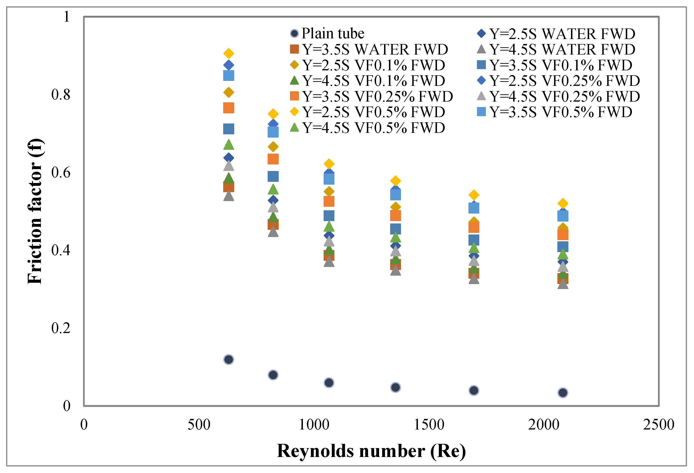
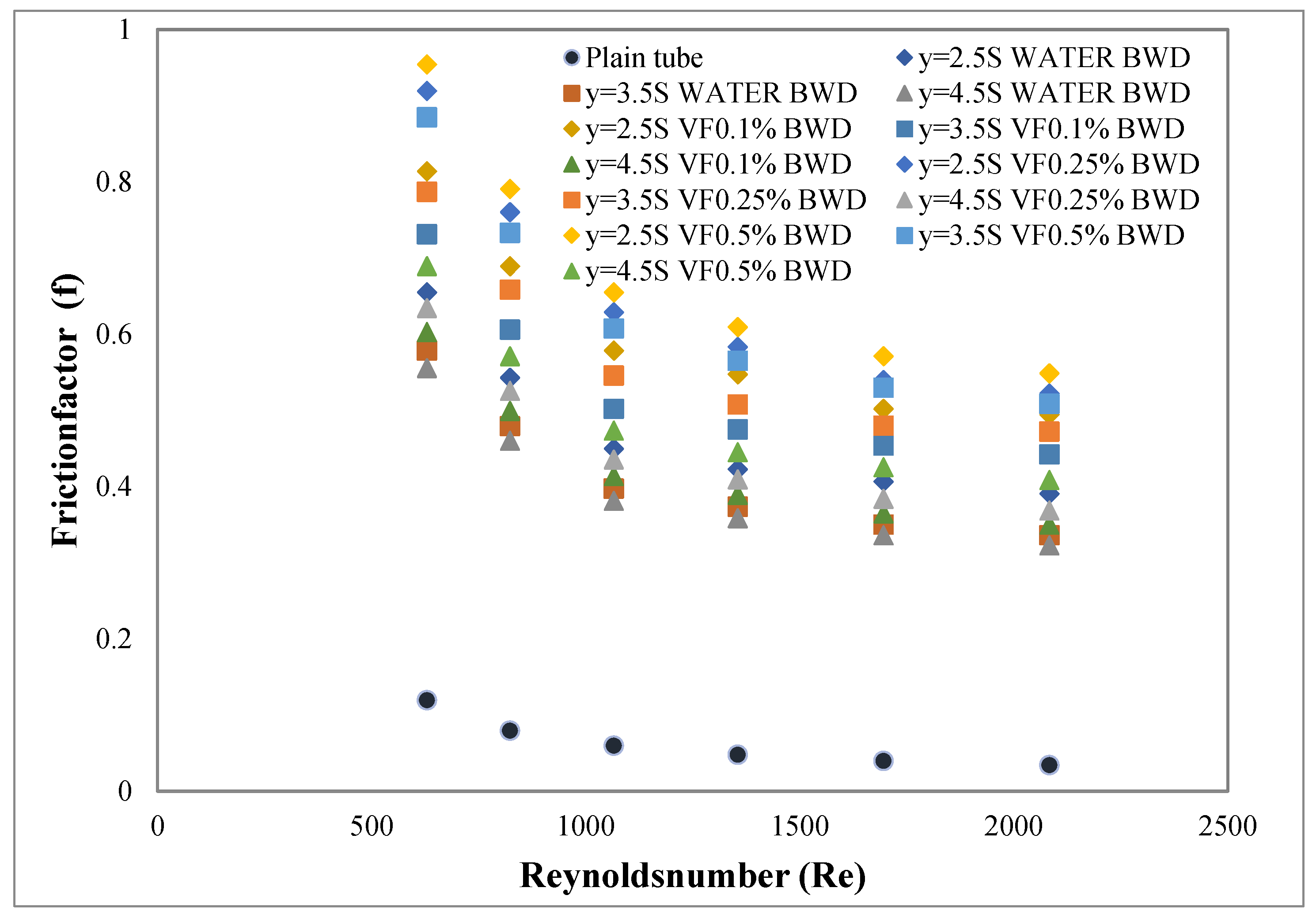
4.3. Effect of the Staggered Conical Strip Insert with Both Forward and Backward Directionsand Nanofluid on the Friction Factor

The variations of the friction factor with the Reynolds number are illustrated in Figure 12 for the staggered conical strip insert with a forward direction of three different twist ratios of Y = 2.5, 3.5, and 4.5 using deionized water and three different fractions of 0.1, 0.25, and 0.5 vol.% of ZrO2/deionized water nanofluid as the working fluid. It was observed that the friction factor decreased with the increasing twist ratio and increased with the decreasing Reynolds number. The friction factor calculated for the test section with conical strip inserts was more than the friction factor for the plain tube due to the intricacies and capacious contact surface area, which induced swirl along the flow path. These phenomena led to increased blockage between the peripheries to the core, also due to the increased viscosity of the working fluid offering more pressure loss in the test section. It was also observed that the conical strip inserts of three twist ratios, viz. 2.5, 3.5, and 4.5, using deionized water equipped in the uniformly heated pipe, showed that the friction factor increased more than the plain tube by 14.27, 13.31, and 10.45 times respectively for the laminar flow regime. This was because of the flow resistance offered by the inserts. The swirl flow triggered by the forward-arrangement conical strip insert recorded the maximum friction factor of 15.07 times for Y = 2.5 of the 0.5 vol.% concentration of nanofluid.
From Figure 13, it can be observed that the friction factor increases with the decrease of the Reynolds number as well as the twist ratio while it surges with the increase of the nanofluid volume concentration. The friction factor intensified at the lower twist ratio and 0.5 vol.% concentration of nanofluid. This was mainly due to the low twist ratio that increased the tangential contact between the vortices of the fluid to the periphery of the test section. Additionally, in the backward arrangement, the convergent portion of the conical strip insert with a larger slant angle offered higher flow resistance for the fluid movement, causing an increased pressure drop. The friction factor is illustrated for the backward pattern in Figure 13. In a test section with conical inserts of twist ratios of Y = 2.5, 3.5, and 4.5 and DI water, the ZrO2/DI water nanofluid was different to that of plain tube with DI water. Therefore, the friction factor enhancement effect of nanofluid in the staggered conical strip insert in the tube was more and discernible because the ZrO2 nanoparticles induced resistance forces in the nanofluid and higher flow blockage contributed to an accumulation of the pressure drop. The friction factor increment for the twist ratios of Y = 2.5, 3.5, and 4.5 increased 15.07, 13.9, and 10.9 times respectively for the 0.5 vol.% of nanofluid at the set of Reynolds number range when compared with DI water. Nevertheless, the conical strip inserts offer a higher heat transfer rate because of their intricacies. The superior geometry of the conical strip inserts employed as turbulators augmented the heat transfer. In the test section, disruption and reattachment of the thermal–hydraulic boundary layers along the flow path influence the formation of vortices in sequence, with more heat transfer promoted than the pressure drop.

4.4. Effect of the Staggered Conical Strip Insert with Both Forward and Backward Directions and Nanofluid on the Thermal Performance Factor (ɳ)

There are many studies that specified that the inserts with nanofluid intensified the convective heat transfer [56,57,58,59,60]. However, the drawback is the heat transfer enhancement is partnered with pressure drop intensification. To evaluate and estimate the system performance, eventually, the thermal performance factor (TPF) was introduced to indicate the merit of the system. By this, amagnitude of TPF above one revealed that the consequence of the heat transfer augmentation in the swirl flow equipment was more than that of the pressure drop intensification. Hence, a value of more than one was shown by the conical strip inserts with ZrO2/DI water nanofluid for the heat transfer application.
The thermal performance factor for three different twist ratios (p/d) of Y = 2.5, 3.5, and 4.5 at 0.5 vol.% of ZrO2/DI water nanofluids was found to be 1.59, 1.51, and 1.33, respectively. The obtained results were substantially more than unity, which proved that the heat transfer augmentation in the swirl flow is more than the pressure loss intensity. From Figure 14, the TPF escalates with a decrease of the twist ratio and an increase of the volume fraction of the nanofluid. As a matter of fact, heat transfer increased irrespective of the Reynolds number, and the rate of heat transfer was enhanced at the lower Reynolds number because of a more viscous effect. From Figure 15, the thermal performance factor recorded was also significant and a similar trend for the staggered conical strip inserts with the backward arrangement was noticed. The maximum values of the thermal performance factor were observed to be 1.24 and 1.62 for the twist ratio of Y = 2.5 using the working fluid DI water and 0.5 vol.% of ZrO2/DI water nanofluid. On the contrary, in the case of the twist ratio Y = 4.5 by means of DI water and 0.5 vol.% of ZrO2/DI water nanofluid, this showed a thermal performance factor value of 1.12 and 1.33, respectively. Compared to the forward direction, the thermal performance factor obtained in staggered conical strip inserts with the backward direction performed better due to more swirl in the fluid.
The present investigation on the thermal performance factor was compared with the open literature, as shown in Table 5. Chougule et al. [57], Saeedinia et al. [58], and K. Yoong Lim et al. [59] carried out tests for various nanofluids and inserts. These tests were considered for the performance evaluation of their experimental investigation on a forced convection system under the laminar flow regime, which is clearly portrayed in Table 5. From this data investigation, it is revealed that the present study on TPF had a descent agreement with the literature data for the laminar flow. However, it needs an optimized study on the twist ratio and volume concentration for industrial applications.

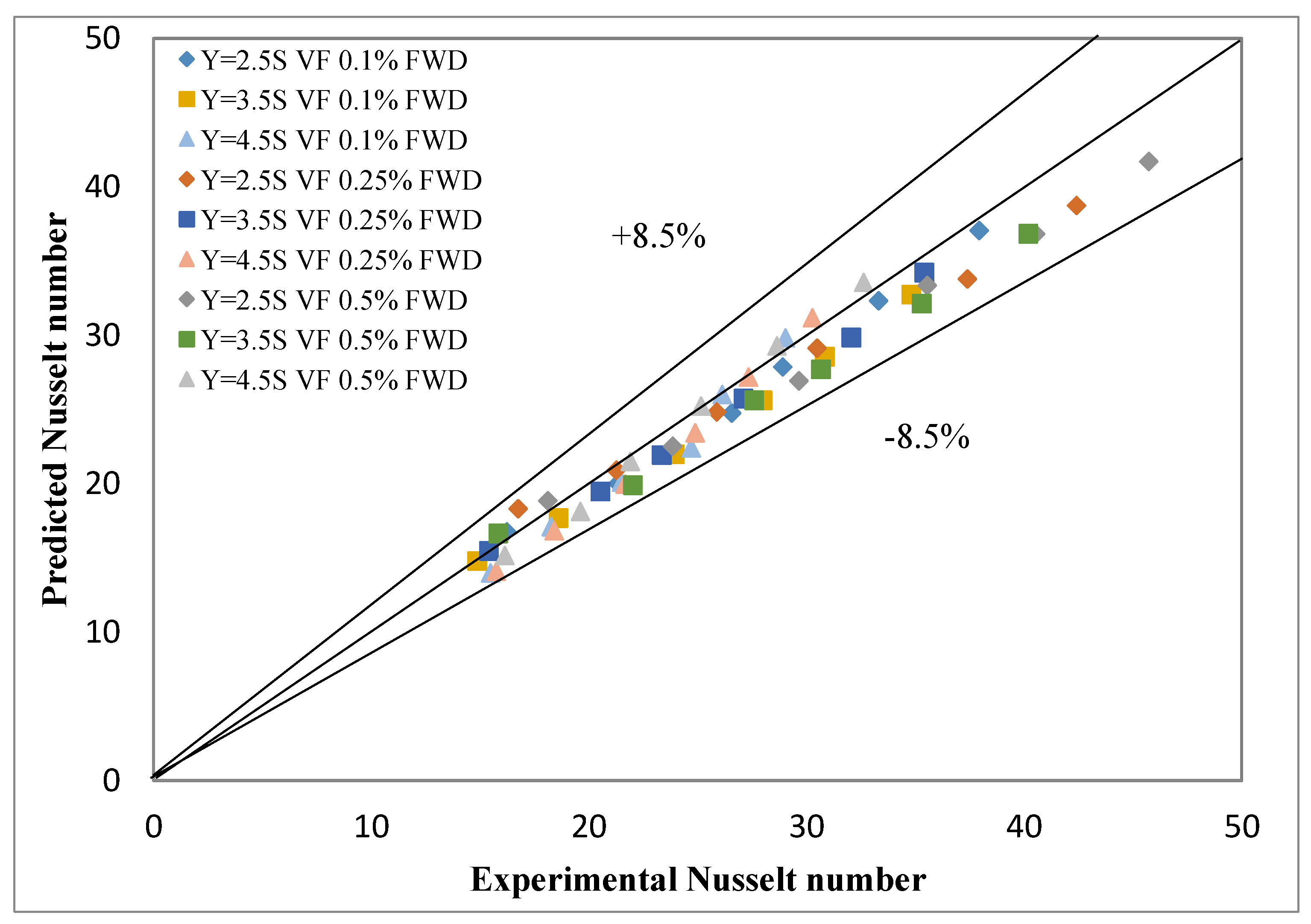
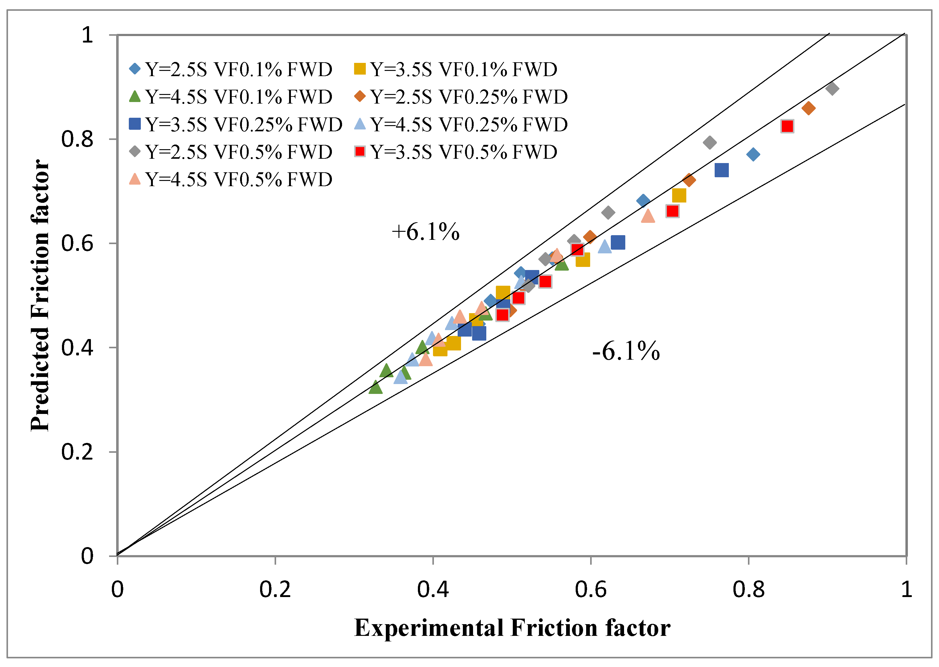
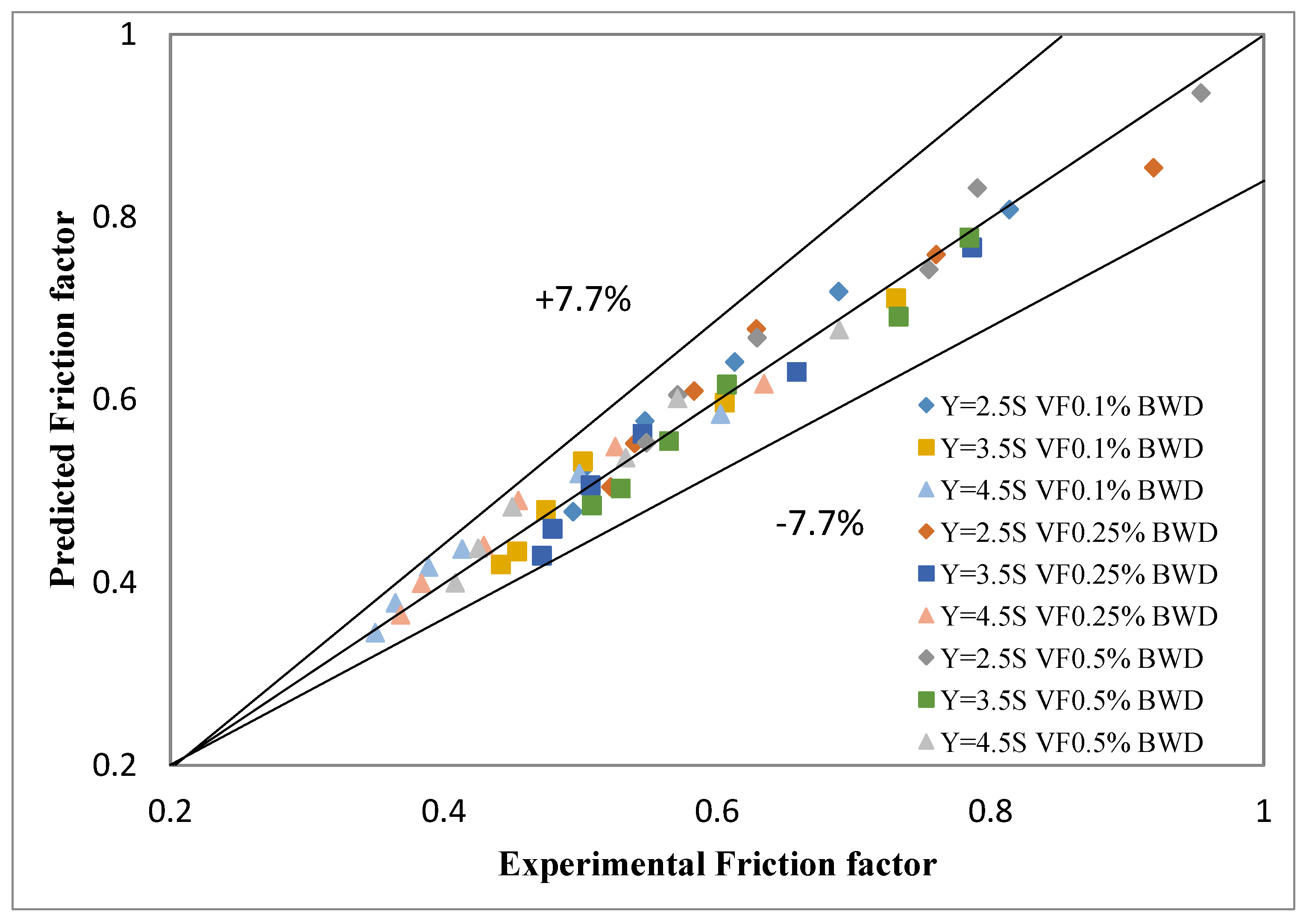
4.5. Development of Empirical Correlations

According to the open literature, it showed that many correlations have been proposed for the combination of nanofluid and insert concerned [61,62,63,64,65]. Abbasian Arani et al.’s [39] insight was pivotal in deriving the correlation. It is very useful for the nanofluid volume fractions involved for the prediction, besides the Reynolds number, Prandtl number, and twist ratios involved to predict the correlations. These Prandtl number values are very significant in this investigation. Additionally, Naik et al. [64] and Sundar et al. [65] studied meticulously the sets of Prandtl number data more elaborately, and the same was verified and decently agreed with the present values presented in Table 1. A similar approach was made to estimate the pressure drop in terms of the friction factor with omission of the influence of the Prandtl number.
The experimental Nusselt number of DI water and ZrO2/DI water nanofluid with the three various conical strip inserts was derived for the curve fitting data from the empirical Equations (20) and (21) for both directions. Thus, the regression equation for the Nusselt number was developed:
N u = 0.173   Re 0.664 Pr 0.4 Y 0.37 ( 1 + φ ) 29.63 ,
N u = 0.147   Re 0.689 Pr 0.4 Y 0.327 ( 1 + φ ) 33.99 .
The experimental friction factor of DI water and ZrO2/DI water nanofluid with the different conical strip inserts was developed for the curve fitting data for a general equation by including the Reynolds number, twist ratio, and volume fractions of nanofluid, thus resulting in the regression Equations (22) and (23) for the friction factor derived for both the directions. The above correlations were developed for the Nusselt number and friction factor involving the present experimental investigations for the forward and backward flow directions of the conical strip inserts as shown in Figure 16, Figure 17, Figure 18 and Figure 19. The estimated values agreed with the experimental values within the ranges of ±8.5% and ±6.1% shown in Figure 16 and Figure 18 for the Nusselt number and friction factor respectively in favor of the forward direction. It could also be perceived from Figure 17 and Figure 19 that the experimental data were in better agreement with the estimated values and the deviations exhibited were within limits of ±9.1% for the Nusselt number and ±7.7% for the friction factor in support of the backward direction:
f = 23.29   Re 0.458 Y 0.539 ( 1 + φ ) 38.033 ,
f = 22.03   Re 0.440 Y 0.551 ( 1 + φ ) 35.76 .

5. Conclusions

The effects of a staggered conical strip with three different twist ratios on the convective heat transfer, friction factor, and thermal performance factor were evaluated respectively with plain tube data for Reynolds number values for the laminar flow region (600 to 2100).
  • The staggered conical strip inserts with a backward direction incorporated in the test section exhibited the higher Nusselt numbers and friction factors compared to that of the forward direction, because the inserts interrupted the thermal and hydraulic boundary layer, thus producing more swirl flow.
  • The conical strip insert is a passive heat transfer enhancement technique to amplify the fluid turbulence with a negligible increase in the pressure drop. The uniform dispersion of higher thermal conductive nanoparticles in the heat transfer fluid further enhances its effective thermal conductivity due to ballistic phonon motion and Brownian motion. The maximum heat transfer and pressure drop in the case of the Y = 2.5 twist ratio with 0.5 vol.% of nanofluid was 145% and15.07 times, respectively.
  • The thermal performance factor was substantially acquired with values of more than unity, which showed the merits of the staggered conical strip inserts in terms of net-energy savings.
  • The predicted values from the correlation equation for the Nusselt number and friction factor were estimated with minimum deviations.
  • The present investigation can be further extended with hybrid nanofluid and conical strip inserts employed in other kinds of heat exchangers, such as shell and tube heat exchangers and radiators for industrial heat transfer applications.

Author Contributions

M.I.S. conceived main concept, investigation and draft preparation, J.J.M. and M.A. Contributed significantly to the resources. S.S. supervised the experimental work. E.A.N. and H.M.A.H. contributed to the Project Administration and Funding Acquisition. All authors have read and agreed to the published version of the manuscript.

Funding

This research was funded by King Saud University, Riyadh, Saudi Arabia under the Researchers Supporting Project number (RSP-2020/164).

Acknowledgments

The authors would like to thank A. Thamizhavel (Department of Condensed Matter Physics) and K.V. Srinivasan (Low Temperature Facility) of Tata Institute of Fundamental Research, Mumbai for providing their technical supports in the characterisation of nanoparticles.

Conflicts of Interest

The authors declare that they have no conflict of interest.

Nomenclature

AArea of cross-section (m2)TPFThermal performance factor.
cpSpecific heat (J/kg K)vVelocity of fluid (m/s)
DiDiameter of test section (m)VVoltage (V)
fFriction factorYTwist ratio
hConvective heat transfer coefficientcoefficient coefficient (W/m2K)Greek Symbols
ICurrent (A)ΔpPressure drop (Pa)
kThermal conductivity (W/m K)µDynamic viscosity (kg/m2 s)
LLength of test section (m)ρDensity (kg./m3)
mMass flow rate (kg/s)Subscripts
NuNusselt numberbfBasefluid
PPitchfFluid
Id
PrPrandtl numberinInlet
qActual heat flux (W/m2)nfNanofluid
QHeat input (W)npNanoparticle
ReReynolds numberoutOutlet
TTemperature (°C)pplain tube
Abbreviations
FWDForward
BWDBackward
DIDeionized

References

  1. Suganthi, K.; Rajan, K. Metal oxide nanofluids: Review of formulation, thermo-physical properties, mechanisms, and heat transfer performance. Renew. Sustain. Energy Rev. 2017, 76, 226–255. [Google Scholar] [CrossRef]
  2. Jang, S.P.; Choi, S.U.S. Role of Brownian motion in the enhanced thermal conductivity of nanofluids. Appl. Phys. Lett. 2004, 84, 4316. [Google Scholar] [CrossRef]
  3. Eid, M.R.; Mahny, K.L. Flow and heat transfer in a porous medium saturated with a Sisko nanofluid over a nonlinearly stretching sheet with heat generation/absorption. Heat Transf. Asian Res. 2018, 47, 54–71. [Google Scholar] [CrossRef]
  4. Esfahani, N.N.; Toghraie, D.; Afrand, M. A new correlation for predicting the thermal conductivity of ZnO–Ag (50%–50%)/water hybrid nanofluid: An experimental study. Powder Technol. 2018, 323, 367–373. [Google Scholar] [CrossRef]
  5. Ding, M.; Liu, C.; Rao, Z. Experimental investigation on heat transfer characteristic of TiO2-H2O nanofluid in microchannel for thermal energy storage. Appl. Therm. Eng. 2019, 160, 114024. [Google Scholar] [CrossRef]
  6. Fares, M.; Mohammad, A.M.; Mohammed, A.S. Heat transfer analysis of a shell and tube heat exchanger operated with grapheme nanofluids. Case Stud. Therm. Eng. 2020, 18, 100584. [Google Scholar] [CrossRef]
  7. Ajeel, R.K.; Salim, W.I.; Sopian, K.; Yusoff, M.Z.; Hasnan, K.; Ibrahim, A.; Al-Waeli, A.H. Turbulent convective heat transfer of silica oxide nanofluid through corrugated channels: An experimental and numerical study. Int. J. Heat Mass Transf. 2019, 145, 118806. [Google Scholar] [CrossRef]
  8. Gravndyan, Q.; Akbari, O.A.; Toghraie, D.; Marzban, A.; Mashayekhi, R.; Karimi, R.; Pourfattah, F. The effect of aspect ratios of rib on the heat transfer and laminar water/TiO2nanofluid flow in a two-dimensional rectangular microchannel. J. Mol. Liq. 2017, 236, 254–265. [Google Scholar] [CrossRef]
  9. Ajeel, R.K.; Salim, W.I.; Hasnan, K. Experimental and numerical investigations of convection heat transfer in corrugated channels using alumina nanofluid under a turbulent flow regime. Chem. Eng. Res. Des. 2019, 148, 202–217. [Google Scholar] [CrossRef]
  10. Hardika, B.K.; Prabhu, S.V. Experimental correlation for critical heat flux in helical coils. Nucl. Eng. Des. 2020, 368, 110759, reprinted in Int. J. Heat Mass Transf. 2020, 146, 118723. [Google Scholar] [CrossRef]
  11. Salem, M.; Eltoukhey, M.; Ali, R.; Elshazly, K.M. Experimental investigation on the hydrothermal performance of a double-pipe heat exchanger using helical tape insert. Int. J. Therm. Sci. 2018, 124, 496–507. [Google Scholar] [CrossRef]
  12. Sivashanmugam, P.; Nagarajan, P. Studies on heat transfer and friction factor characteristics of laminar flow through a circular tube fitted with right and left helical screw-tape inserts. Exp. Therm. Fluid Sci. 2007, 32, 192–197. [Google Scholar] [CrossRef]
  13. Wang, Y.; Alvarado, J.L.; Terrell, W., Jr. Thermal performance of helical coils with reversed loops and wire coil inserts. Int. J. Heat Mass Transf. 2020, 146, 118723. [Google Scholar] [CrossRef]
  14. Hamid, K.A.; Azmi, W.; Mamat, R.; Sharma, K. Heat transfer performance of TiO2–SiO2nanofluids in a tube with wire coil inserts. Appl. Therm. Eng. 2019, 152, 275–286. [Google Scholar] [CrossRef]
  15. Pérez-García, J.; García, A.; Herrero-Martín, R.; Solano, J. Experimental correlations on critical Reynolds numbers and friction factor in tubes with wire-coil inserts in laminar, transitional and low turbulent flow regimes. Exp. Therm. Fluid Sci. 2018, 91, 64–79. [Google Scholar] [CrossRef]
  16. Sundar, L.S.; Bhramara, P.; Kumar, N.R.; Singh, M.K.; Sousa, A. Experimental heat transfer, friction factor and effectiveness analysis of Fe3O4 nanofluid flow in a horizontal plain tube with return bend and wire coil inserts. Int. J. Heat Mass Transf. 2017, 109, 440–453. [Google Scholar] [CrossRef]
  17. Bahiraei, M.; Mazaheri, N.; Aliee, F.; Safaei, M.R. Thermo-hydraulic performance of a biological nanofluid containing graphene nanoplatelets within a tube enhanced with rotating twisted tape. Powder Technol. 2019, 355, 278–288. [Google Scholar] [CrossRef]
  18. Moya-Rico, J.; Molina, A.; Belmonte, J.; Tendero, J.C.; Almendros-Ibáñez, J. Experimental characterization of a double tube heat exchanger with inserted twisted tape elements. Appl. Therm. Eng. 2020, 174, 115234. [Google Scholar] [CrossRef]
  19. Nakhchi, M.; Esfahani, J. Performance intensification of turbulent flow through heat exchanger tube using double V-cut twisted tape inserts. Chem. Eng. Process. Process Intensif. 2019, 141, 107533. [Google Scholar] [CrossRef]
  20. Murugesan, P.; Mayilsamy, K.; Suresh, S. Heat transfer in tubes fitted with trapezoidal-cut and plain twisted tape inserts. Chem. Eng. Commun. 2011, 198, 886–904. [Google Scholar] [CrossRef]
  21. Garg, M.; Nautiyal, H.; Khurana, S.; Shukla, M. Heat transfer augmentation using twisted tape inserts: A review. Renew. Sustain. Energy Rev. 2016, 63, 193–225. [Google Scholar] [CrossRef]
  22. Esmaeilzadeh, E.; Almohammadi, H.; Nokhosteen, A.; Motezaker, A.; Omrani, A.N. Study on heat transfer and friction factor characteristics of γ-Al2O3/water through circular tube with twisted tape inserts with different thicknesses. Int. J. Therm. Sci. 2014, 82, 72–83. [Google Scholar] [CrossRef]
  23. Mohammed, H.A.; Abuobeida, I.A.A.; Vuthaluru, H.B.; Liu, S. Two-phase forced convection of nanofluids flow in circular tubes using convergent and divergent conical rings inserts. Int. Commun. Heat Mass Transf. 2019, 101, 10–20. [Google Scholar] [CrossRef]
  24. Rathnakumar, P.; Iqbal, S.M.; Michael, J.J.; Suresh, S. Study on performance enhancement factors in turbulent flow of CNT/water nanofluid through a tube fitted with helical screw louvered rod inserts. Chem. Eng. Process. Process. Intensif. 2018, 127, 103–110. [Google Scholar] [CrossRef]
  25. Bahiraei, M.; Mazaheri, N.; Alighardashi, M. Development of chaotic advection in laminar flow of a non-Newtonian nanofluid: A novel application for efficient use of energy. Appl. Therm. Eng. 2017, 124, 1213–1223. [Google Scholar] [CrossRef]
  26. Li, P.; Liu, Z.; Liu, W.; Chen, G. Numerical study on heat transfer enhancement characteristics of tube inserted with centrally hollow narrow twisted tapes. Int. J. Heat Mass Transf. 2015, 88, 481–491. [Google Scholar] [CrossRef]
  27. Amani, M.; Amani, P.; Kasaeian, A.; Mahian, O.; Yan, W.-M. Two-phase mixture model for nanofluid turbulent flow and heat transfer: Effect of heterogeneous distribution of nanoparticles. Chem. Eng. Sci. 2017, 167, 135–144. [Google Scholar] [CrossRef]
  28. Babu, J.R.; Kumar, K.K.; Rao, S.S. State-of-art review on hybrid nanofluids. Renew. Sustain. Energy Rev. 2017, 77, 551–565. [Google Scholar] [CrossRef]
  29. Kumar, D.D.; Arasu, A.V. A comprehensive review of preparation, characterization, properties and stability of hybrid nanofluids. Renew. Sustain. Energy Rev. 2018, 81, 1669–1689. [Google Scholar] [CrossRef]
  30. Das, P.K. A review based on the effect and mechanism of thermal conductivity of normal nanofluids and hybrid nanofluids. J. Mol. Liq. 2017, 240, 420–446. [Google Scholar] [CrossRef]
  31. Pal, S.; Saha, S.K. Laminar fluid flow and heat transfer through a circular tube having spiral ribs and twisted tapes. Exp. Therm. Fluid Sci. 2015, 60, 173–181. [Google Scholar] [CrossRef]
  32. Man, C.; Lv, X.; Hu, J.; Sun, P.; Tang, Y. Experimental study on effect of heat transfer enhancement for single-phase forced convective flow with twisted tape inserts. Int. J. Heat Mass Transf. 2017, 106, 877–883. [Google Scholar] [CrossRef]
  33. You, Y.; Fan, A.; Liu, W.; Huang, S. Thermo-hydraulic characteristics of laminar flow in an enhanced tube with conical strip inserts. Int. J. Therm. Sci. 2012, 61, 28–37. [Google Scholar] [CrossRef]
  34. Liu, P.; Zheng, N.; Shan, F.; Liu, Z.; Liu, W. Heat transfer enhancement for laminar flow in a tube using bidirectional conical strip inserts. Int. J. Heat Mass Transf. 2018, 127, 1064–1076. [Google Scholar] [CrossRef]
  35. Pourramezan, M.; Ajam, H. Modeling for thermal augmentation of turbulent flow in a circular tube fitted with twisted conical strip inserts. Appl. Therm. Eng. 2016, 105, 509–518. [Google Scholar] [CrossRef]
  36. Chopkar, M.; Das, P.; Manna, I. Thermal characterization of a nanofluid comprising nanocrystalline ZrO2 dispersed in water and ethylene glycol. Philos. Mag. 2007, 87, 4433–4444. [Google Scholar] [CrossRef]
  37. Mohammed, H.A.; Hasan, H.A.; Wahid, M. Heat transfer enhancement of nanofluids in a double pipe heat exchanger with louvered strip inserts. Int. Commun. Heat Mass Transf. 2013, 40, 36–46. [Google Scholar] [CrossRef]
  38. Aghayari, R.; Maddah, H.; Zarei, M.; Dehghani, M.; Mahalle, S.G.K. Heat transfer of nanofluid in a double pipe heat exchanger. Int. Sch. Res. Not. 2014, 2014, 1–7. [Google Scholar] [CrossRef] [Green Version]
  39. Arani, A.A.A.; Amani, J. Experimental study on the effect of TiO2—Water nanofluid on heat transfer and pressure drop. Exp. Therm. Fluid Sci. 2012, 42, 107–115. [Google Scholar] [CrossRef]
  40. Iqbal, S.M.; Raj, C.S.; Michael, J.J.; Irfan, A.M. A comparative investigation of Al2O3/H2O, SiO2/H2O and ZrO2/H2O nanofluid for heat transfer applications. Dig. J. Nanomater. Biostruct. 2017, 12, 255–263. [Google Scholar]
  41. Pak, B.C.; Cho, Y.I. Hydrodynamic and heat transfer study of dispersed fluids with submicron metallic oxide particles. Exp. Heat Transf. Int. J. 1998, 11, 151–170. [Google Scholar] [CrossRef]
  42. Xuan, Y.; Roetzel, W. Conceptions for heat transfer correlation of nanofluids. Int. J. Heat Mass Transf. 2000, 43, 3701–3707. [Google Scholar] [CrossRef]
  43. Nakhchi, M.; Esfahani, J. Numerical investigation of turbulent Cu-water nanofluid in heat exchanger tube equipped with perforated conical rings. Adv. Powder Technol. 2019, 30, 1338–1347. [Google Scholar] [CrossRef]
  44. Fan, A.; Deng, J.; Guo, J.; Liu, W. A numerical study on thermo-hydraulic characteristics of turbulent flow in a circular tube fitted with conical strip inserts. Appl. Therm. Eng. 2011, 31, 2819–2828. [Google Scholar] [CrossRef]
  45. Minakov, A.; Guzei, D.; Meshkov, K.; Popov, I.; Shchelchkov, A. Experimental study of turbulent forced convection of nanofluid in channels with cylindrical and spherical hollows. Int. J. Heat Mass Transf. 2017, 115, 915–925. [Google Scholar] [CrossRef] [Green Version]
  46. Sun, B.; Zhang, Z.; Yang, D. Improved heat transfer and flow resistance achieved with drag reducing Cu nanofluids in the horizontal tube and built-in twisted belt tubes. Int. J. Heat Mass Transf. 2016, 95, 69–82. [Google Scholar] [CrossRef]
  47. Ding, Y.; Chen, H.; He, Y.; Lapkin, A.; Yeganeh, M.; Šiller, L.; Butenko, Y.V. Forced convective heat transfer of nanofluids. Adv. Powder Technol. 2007, 18, 813–824. [Google Scholar] [CrossRef]
  48. Mirfendereski, S.; Abbassi, A.; Saffar-Avval, M. Experimental and numerical investigation of nanofluid heat transfer in helically coiled tubes at constant wall heat flux. Adv. Powder Technol. 2015, 26, 1483–1494. [Google Scholar] [CrossRef]
  49. Usui, H. Enhancement of heat transfer by a combination of internally grooved rough tube and twisted tape. Int. Chem. Eng. 1986, 26, 97–104. [Google Scholar]
  50. Kine, S.J.; McClintock, F.A. Describing uncertainties in single-sample experiments. J. Mech. Eng. 1953, 3, 3–8. [Google Scholar]
  51. Ponnada, S.; Subrahmanyam, T.; Naidu, S. A comparative study on the thermal performance of water in a circular tube with twisted tapes, perforated twisted tapes and perforated twisted tapes with alternate axis. Int. J. Therm. Sci. 2019, 136, 530–538. [Google Scholar] [CrossRef]
  52. Shah, R.K. Thermal entry length solutions for the circular tube and parallel plates. In Proceedings of the Third National Heat Mass Transfer Conference, Indian Institute of Technology, Bombay, Indian, 11–13 December 1975; p. 1, Paper No. HMT-11-75. [Google Scholar]
  53. Kristiawan, B.; Santoso, B.; Wijayanta, A.T.; Aziz, M.; Miyazaki, T. Heat transfer enhancement of TiO2/water nanofluid at laminar and turbulent flows: A numerical approach for evaluating the effect of nanoparticle loadings. Energies 2018, 11, 1584. [Google Scholar] [CrossRef] [Green Version]
  54. Ahmad, S.; Abdullah, S.; Sopian, K. Numerical and experimental analysis of the thermal performances of SiC/water and Al2O3/water nanofluid inside a circular tube with constant-increased-pr twisted tape. Energies 2020, 13, 2095. [Google Scholar] [CrossRef]
  55. Chamkha, A.J.; Selimefendigil, F. Forced convection of pulsating nanofluid flow over a backward facing step with various particle shapes. Energies 2018, 11, 3068. [Google Scholar] [CrossRef] [Green Version]
  56. Goudarzi, K.; Jamali, H. Heat transfer enhancement of Al2O3-EG nanofluid in a car radiator with wire coil inserts. Appl. Therm. Eng. 2017, 118, 510–517. [Google Scholar] [CrossRef] [Green Version]
  57. Chougule, S.S.; Sahu, S.K. Heat transfer and friction characteristics of Al2O3/water and CNT/water nanofluids in transition flow using helical screw tape inserts. Chem. Eng. Process. 2015, 88, 201578–201588. [Google Scholar] [CrossRef]
  58. Saeedinia, M.; Behabadi, M.A.; Nasr, M. Experimental study on heat transfer and pressure drop of nanofluid flow in a horizontal coiled wire inserted tube under constant heat flux. Exp. Therm. Fluid Sci. 2012, 36, 158–168. [Google Scholar] [CrossRef]
  59. Lim, K.Y.; Hung, Y.M.; Tan, B.T. Performance evaluation of twisted-tape insert induced swirl flow in a laminar thermally developing heat exchanger. Appl. Therm. Eng. 2017, 121, 652–661. [Google Scholar] [CrossRef]
  60. Suresh, S.; Venkitaraj, K.P.; Selvakumar, P. Comparative study on thermal performance of helical screw tape inserts in laminar flow using Al2O3/water and CuO/water nanofluids. Superlattices Microstruct. 2011, 49, 608–622. [Google Scholar] [CrossRef]
  61. Chandrasekar, M.; Suresh, S.; Bose, A.C. Experimental studies on heat transfer and friction factor characteristics of Al2O3/water nanofluid in a circular pipe under laminar flow with wire coil inserts. Exp. Therm. Fluid Sci. 2010, 34, 122–130. [Google Scholar] [CrossRef]
  62. Khoshvaght-Aliabadi, M.; Shabanpour, H.; Alizadeh, A.; Sartipzadeh, O. Experimental assessment of different inserts inside straight tubes: Nanofluid as working media. Chem. Eng. Process. Process Intensif. 2015, 97, 1–11. [Google Scholar] [CrossRef]
  63. Wongcharee, K.; Eiamsa-Ard, S. Friction and heat transfer characteristics of laminar swirl flow through the round tubes inserted with alternate clockwise and counter-clockwise twisted-tapes. Int. Commun. Heat Mass Transf. 2011, 38, 348–352. [Google Scholar] [CrossRef]
  64. Naik, M.T.; Janardana, G.R.; Sundar, L.S. Experimental investigation of heat transfer and friction factor with water-propylene glycol based CuO nanofluid in a tube with twisted tape inserts. Int. Commun. Heat Mass Transf. 2013, 46, 13–21. [Google Scholar] [CrossRef]
  65. SyamSundar, L.; Sousa, A.; Singh, M.K. Heat transfer enhancement of low volume concentration of carbon nanotube-Fe3O4/water hybrid nanofluids in a tube with twisted tape inserts under turbulent flow. J.Therm. Sci. Eng. Appl. 2015, 7, 1–12. [Google Scholar]
Figure 1. XRD pattern for ZrO2 nanoparticles.
Energies 13 04554 g001
Figure 2. SEM image of the ZrO2 (Zirconia) nanoparticles.
Energies 13 04554 g002
Figure 3. TEM image of ZrO2/DI water nanofluid.
Energies 13 04554 g003
Figure 4. Schematic of the conical strip insert with a forward (FWD) arrangement in the test section.
Energies 13 04554 g004
Figure 5. Photographic view of the staggered conical strip insert with Y = 2.5, 3.5, and 4.5.
Energies 13 04554 g005
Figure 6. Schematic diagram of the staggered conical strip inserts with forward (FWD) and backward (BWD) arrangements.
Energies 13 04554 g006
Figure 7. Schematic arrangement of the experimental test facility.
Energies 13 04554 g007
Figure 8. Validation of the experimental Nusselt number for a plain tube under laminar flow.
Energies 13 04554 g008
Figure 9. Validation of the experimental friction factor for a plain tube under laminar flow.
Energies 13 04554 g009
Figure 10. Nusselt number versus Reynolds number for the staggered conical strip insert with a forward arrangement using deionized water and ZrO2/deionized water nanofluids under laminar flow conditions.
Energies 13 04554 g010
Figure 11. Nusselt number versus Reynolds number for the staggered conical strip insert with a backward arrangement using deionized water and ZrO2/deionized water nanofluids under laminar flow conditions.
Energies 13 04554 g011
Figure 12. Friction factor versus Reynolds number for a staggered conical strip insert with the forward arrangement using deionized water and ZrO2/deionized water nanofluids under laminar flow conditions.
Energies 13 04554 g012
Figure 13. Friction factor versus Reynolds number for a staggered conical strip insert with the backward arrangement using deionized water and ZrO2/deionized water nanofluids under laminar flow conditions.
Energies 13 04554 g013
Figure 14. Thermal performance factor versus the Reynolds number for a staggered conical strip insert with the forward arrangement using deionized water and ZrO2/deionized water nanofluids under laminar flow conditioned.
Energies 13 04554 g014
Figure 15. Thermal performance factor versus the Reynolds number for a staggered conical strip insert with the backward arrangement using deionized water and ZrO2/deionized water nanofluids under laminar flow conditioned.
Energies 13 04554 g015
Figure 16. Predicted versus experimental Nusselt number for a staggered conical strip insert with the forward arrangement using deionized water and ZrO2/deionized water nanofluids under laminar flow conditions.
Energies 13 04554 g016
Figure 17. Predicted versus experimental Nusselt number for a staggered conical strip insert with the backward arrangement using deionized water and ZrO2/deionized water nanofluids under laminar flow conditions.
Energies 13 04554 g017
Figure 18. Predicted versus experimental friction factor for a staggered conical strip insert with the forward arrangement using deionized water and ZrO2/deionized water nanofluids under laminar flow conditions.
Energies 13 04554 g018
Figure 19. Predicted versus experimental friction factor for a staggered conical strip insert with the backward arrangement using deionized water and ZrO2/deionized water nanofluids under laminar flow conditions.
Energies 13 04554 g019
Table 1. Thermo-physical properties of ZrO2 nanoparticles, deionized water, and ZrO2/DI water nanofluids.
Nanoparticle, DI Water and NanofluidsDensity (g/cm3)Specific Heat (J/kg-K)Dynamic Viscosity (mPa-sec)Thermal Conductivity (W/m-K)Prandtl Number (Pr = µ cp/k)
ZrO25600418-2.80-
DI Water100041720.7760.6005.39
φ = 0.10%1004.64157.180.8330.6155.63
φ = 0.25%1011.54125.950.9120.6325.95
φ = 0.50%10234075.080.9560.6575.92
Table 2. Technical details of the conical strip inserts.
S. NoPitch in mmDiameter in mmTwist Ratio (Y)
1.25102.5:1
2.35103.5:1
3.45104.5:1
Table 3. The uncertainty of the measuring instruments.
S. No.Measured QuantityAccuracy
1Fluid temperature (Tf)±0.1 °C
2Wall temperature (Tw)±0.1 °C
3Pressure drop (Δh)±0.0033 m
4Pipe inner diameter (Di)±0.000025 m
6Pipe length (L)±0.001 m
7Mass flow rate (m)±6.02 × 10⁻⁵ kg/s
8Voltage (V)±0.600 V
9Current (I)±0.0375 A
Table 4. Heat transfer augmentation (in %) of conical strip inserts at different twist ratios and volume concentrations of ZrO2/DI water nanofluids.
Twist RatiosVolume Concentration (%)
0.10.250.5
FWDBWDFWDBWDFWDBWD
Y = 2.591.27109.83113.86127.28130.56145.02
Y = 3.575.5986.4778.6291.94102.72116.57
Y = 4.546.4160.6752.6567.9364.5280.92
Table 5. Comparison of the thermal performance factor with previous literature.
Authors and ReferenceType of InsertP/d Ratio RangeWorking Fluid and Range of Reynolds NumberThermal Performance Factor Range
Present dataConical strip insert2.5 ≤ P/d ≤ 4.5ZrO2/DI water
600 ≤ Re ≤ 2100
1.1–1.67
S. Chougule [57]Screw Tape1.5 ≤ P/d ≤ 3CNT/water
0.1 ≤ φ ≤ 1
15,000 ≤ Pe ≤ 30,000
1.24–1.46
M. Saeedinia [58]Wire coil1.79 ≤ P/d ≤ 2.5CuO/Base oil
0.07 ≤ φ ≤ 3
10 ≤ Re ≤ 120
0.92–1.2
K. Yoong Lim [59]Twisted tape2.5 ≤ P/d ≤ 6Water
400 ≤ Re ≤ 1400
0.85–1.6

