Article

Experimental Study on Thermal Response Characteristics of Indoor Environment with Modular Radiant Cooling System

School of Mechanical Engineering, Tongji University, Shanghai 201804, China
*
Author to whom correspondence should be addressed.
Energies 2020, 13(19), 5012; https://doi.org/10.3390/en13195012
Submission received: 3 September 2020 / Revised: 20 September 2020 / Accepted: 22 September 2020 / Published: 24 September 2020
(This article belongs to the Section G: Energy and Buildings)

Abstract

:
The radiant cooling system has a substantial energy-saving effect and can be widely applied in different kinds of low-energy buildings. This article reports the experimental study of the design strategy of the radiant cooling system in low-energy buildings from the perspective of thermal response characteristics of an indoor environment. Two types of a modular radiant cooling system, namely, the copper tube radiant cooling (CTRC) and the capillary radiant cooling (CRC) systems, were investigated. The experiments were conducted in two office rooms characterized by low energy consumption. In total, 16 cases (eight for CTRC and eight for CRC) were analyzed, covering supply water temperature with a range of 12–19 °C. The experimental results show that the supply water temperature has a more substantial effect on the temperature distribution of the envelope for CTRC, than that of CRC. The indoor air temperature stratification is acceptable in the active area of the occupant with a modular radiant cooling system. Moreover, the thermal response of the envelope is highly sensitive to the lower supply water temperature (below 16 °C) using CTRC and to the higher supply water temperature (above 15 °C) using CRC. The low supply water temperature (below 15 °C) can improve the thermal stability speed of indoor air to a greater degree using CTRC, than that of CRC. The supply water temperature for CTRC with 15–16 °C, and 18–19 °C for CRC in low-energy buildings can exert an optimal cooling benefit.

1. Introduction

China’s urbanization process has promoted the rapid development of the air conditioning industry. Building’s energy consumption accounted for about 23% of total energy consumption in 2015, of which the energy consumption of air-conditioning units accounted for more than 30% [1]. Sustainable development required high-efficiency heating/cooling technologies to satisfy the indoor thermal comfort with low energy consumption [2]. The radiant cooling system has a high potential for energy-saving and economy, compared with the air-based cooling system [3]. The former has been applied in different types of buildings, such as office buildings and airports for its reduced energy consumption and high thermal comfort. With the merits of the radiant cooling system and the rapid development of low-energy buildings, its popularity has increasing over the last several decades [4]. However, thermal inertia in the indoor thermal environment becomes a key issue when the radiant cooling system is applied, specifically in-low energy buildings where the envelope has a good thermal insulation performance. The radiant cooling system must consume less energy and the indoor thermal environment should respond quickly to achieve thermal comfort, which limits the popularization and application of the radiant cooling system.
Research on improving indoor thermal responses with the radiant system has mainly focused on the control strategies [4] and system configuration [5]. Radiant cooling must be controlled to prevent surface condensation [6] and reduce energy consumption [7]. Qin et al. [8] analyzed the dynamic performance of the radiant floor cooling system based on semi-tensor product and fuzzy control. The results showed that the time delay of the floor surface and indoor air temperature are not evident with the reduction in amplitude vibration of the outdoor air temperature. Zakula et al. [9] implemented model predictive controls to determine the cooling strategy based on weather and load prediction during the next 24 h. Ferkl and Jan [10] proposed a simulation model, which can be used for energy optimization for the ceiling radiant cooling system. The model is ready to be used in modern multidimensional controllers such as model-based predictive controllers. Moreover, the outdoor air temperature was used to control the supply water temperature provided to the concrete slab, based on heuristic rules [11,12]. Limiting the operation time has been reported to improve the thermal inertia of the radiant system and reduce energy consumption [13,14]. Furthermore, when applying the radiant cooling system, specifically in the hot summer and humid climates, the condensation on radiant surfaces must be prevented by the controlling the water temperature [15] or combining the radiant cooling system with the ventilation system [16].
In practical application, system configuration, supply water temperature and water flow rate are often used for the radiant cooling system controls to achieve indoor thermal comfort or energy savings. The supply water temperature and water flow rate depend on the outdoor air temperature and room set-point temperature [17,18]. In addition, the slab or surface temperature can be used as a controlled parameter to improve energy efficiency or avoid local thermal discomfort [19]. Lim et al. [20] suggested that the floor surface temperature needs to be used for system control of radiant floor cooling to avoid overcooling. Rhee et al. [21] conducted a simulation study and indicated that room temperature control needs to be implemented to improve comfort and to achieve further energy savings. The capacity of the radiant system also depends on the system parameters which affects the heat exchange between the radiant surface and the indoor environment, the heat conduction between the surface and tubes, and the heat convection between the water and tubes [22]. Zhao et al. [23] revealed that the cooling capacity of the radiant floor at 18 °C increases from 30–40 W/m2 to 110–140 W/m2 when transient solar radiation exists. Lehmann et al. [24] investigated the application range of TABS (Thermally Activated Building System) based on the simulation study and indicated that the re-cooling period of the building fabric can be extended to 24 h per day and reduce the peak load up to 50 % with a high supply water temperature. Xie et al. [25] investigated the heat transfer in the capillary of the ceiling radiant cooling system based on CFD (computational fluid dynamics) simulations. They revealed that inlet water temperature and tube spacing affect the cooling capacity of the ceiling radiant panel. Feng et al. [26] proposed a new method to estimate the cooling capacity of the radiant cooling system using the mean temperature difference between the water and the room. This method relates the thermal capacity to the water temperature. However, present studies cannot solve the adaptability problem of the radiant cooling system in low-energy buildings well, due to the complexity of the heat transfer process of indoor thermal environment with radiant cooling system.
A modular radiant panel for cooling was designed in this study to further promote the popularity of low energy buildings which are beneficial to energy-saving cities and society development. This panel aims to be energy-saving and achieve a quick response to the indoor environment, simultaneously, by changing the form of the radiant terminal. Such a radiant cooling terminal, that is, the structure of the copper tube and capillary, was built in the Lab to investigate the optimal design strategy of this novel radiant terminal. A series of tests were conducted including the performance of different structures of the radiant panel, temperature distribution in the envelope and indoor air, and the effect of supply water temperature on the indoor thermal response. According to the experimental results, the range of supply water temperatures in the design of two types of the radiant cooling terminal (copper tube radiant cooling (CTRC) and capillary radiant cooling (CRC)) is determined.

2. Experimental Description

2.1. Structure of Modular Radiant Terminal

The radiant cooling system in the current market could be mainly divided into the following three types: radiant floor cooling system [27], radiant cooling ceiling system [28], and wall cooling system [29]. The pipe can be embedded into the building structures or slab, and the radiant terminal always occupies the entire surface. A novel type of modular radiant terminal is proposed, which refer to copper tube radiant cooling (CTRC) terminal and capillary radiant cooling (CRC) terminals, as shown in Figure 1.
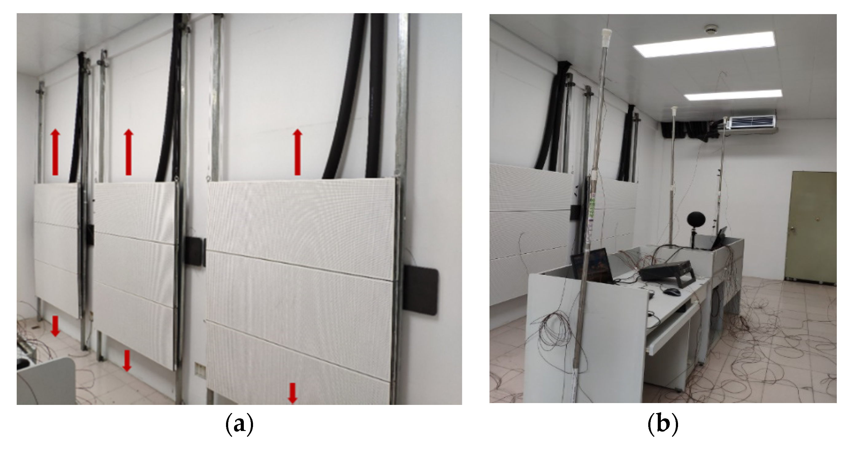
The modular radiant cooling system comprised six independent radiant panels installed on the wall. The single radiant module is 1.5 m in width and 1.0 m in length. The top surface of the radiant module is a galvanized steel sheet with a water tube attached behind. There are two kinds of water tube, copper tube and capillary (material is PPR (pentatricopeptide repeats)), with 0.012 m in diameter and 0.1 m pipe spacing and 0.004 m diameter and 0.01 m pipe spacing, respectively. The bottom panel is covered with a 0.05 m thick thermal insulation layer to ensure that the heat transfer from the water to the panel is maximized. Each radiant module can be moved on the wall in the vertical direction and controlled individually, as shown in Figure 2. The inlet and outlet of each modular radiant terminal are connected to a water separator and water collector, respectively. The water supply system for radiant cooling panels is composed of an air source heat pump, buffer tank, water pump, valves, water separator, water collector, flow meter and other accessories.

2.2. Brief of the Experiment System

The experiments were conducted in two office rooms in Tongji University, Shanghai, China and the size of each room with 5.8 m (l) × 3.2 m (w) × 3.2 m (h). There is one exterior wall facing south, two windows of 1.8 m × 0.85 m. The U-value of exterior wall, interior wall, roof and window are 0.4 W/m2·K, 0.5 W/m2·K, 0.3 W/m2·K and 1.2 W/m2·K, respectively, configured to comply with the prescriptive requirements of the technical standards for nearly zero energy buildings [30]. The modular radiant terminal was installed on the wall, where one room was equipped with the CTRC terminal and another was equipped with the CRC terminal.
Four simulated work spaces consisting of load simulators, computers, desks and chairs were set up to simulate more realistic office conditions. The load simulators were adjusted to produce a sensible heat dissipation rate of approximately 80 W each, corresponding to the heat dissipation of the human body.
A schematic diagram of the testing system is shown in Figure 3. Fourteen temperature measurements were collected on the walls, floor, ceiling, window and radiant panels, with every surface having two temperature sensors of T-type thermocouples with an inherent accuracy of ±0.3 °C. The data of the two measurements are averaged in the later analysis of the results. Indoor air temperature was measured at three positions in the horizontal direction and four in the vertical direction using T-type thermocouples. The horizontal measurement points were evenly spaced and labeled with #1, #2 and #3 (1.5 m, 3 m, and 4.5 m away from exterior wall, respectively). The vertical measurement points were located at the height of 0.1 m, 1 m, 1.5 m, and 2 m above the floor, respectively. Aluminum foil was used to isolate the thermocouple from radiant plane to eliminate the influence of radiation heat transfer on the air temperature measurement. The chilled supply water temperature was measured at the outlet of the buffer tank and the water temperature at the inlet and outlet of each modular radiant terminal was measured using thermal resistance temperature sensor PT100 with an inherent accuracy of ±0.3 °C. Flow meter was used to measure the water flow, which has an inherent accuracy of ±0.2%. The temperature was recorded using the data acquisition unit Fluke 2638A Hydra Series III at an interval of one-minute for analysis purpose.

2.3. Experimental Test Procedure

Tests were conducted in July and August 2019 in Tongji University, which has a hot summer and cold winter climate. The choice of test period was based on consideration that there is little variation in outdoor climatic conditions every day. The sixteen test cases (8 for the CTRC and 8 for CRC) are shown in Table 1.
In this research, the supply water temperature of the radiant cooling system is the only variable that changed, from 12 °C to 19 °C. The area of the modular radiant terminal is 3 m2 (two radiant modules), with the installed position of 0 m above the floor and in the middle of the wall.
For experimental comparisons, first, the temperature distributions of the envelopes and indoor air were compared for the two types of radiant cooling system under different supply water temperatures. Then, the thermal response characteristics of the indoor thermal environment with the change of supply water temperature were analyzed.
Before the test, the apparatus has been checked and the indoor thermal environment was steady. Among all the experimental conditions, the radiant cooling system was run for 4 h continuously from 08:00 to 12:00. The adjacent room was air-conditioned and the indoor temperature was set to 26 °C so that the heat transfer from the adjacent room could be ignored.

2.4. Date Analyzing Method

The dynamic thermal response of the room with the radiant cooling system includes the hysteresis of the room at the beginning of the system operation and the thermal stability of the room with the continuous operation of the system. In terms of the hysteresis of the room, attenuation delay time and attenuation delay amplitude are used in this study. Moreover, the stabilization time and steady value are used to characterize the thermal stability of the room.
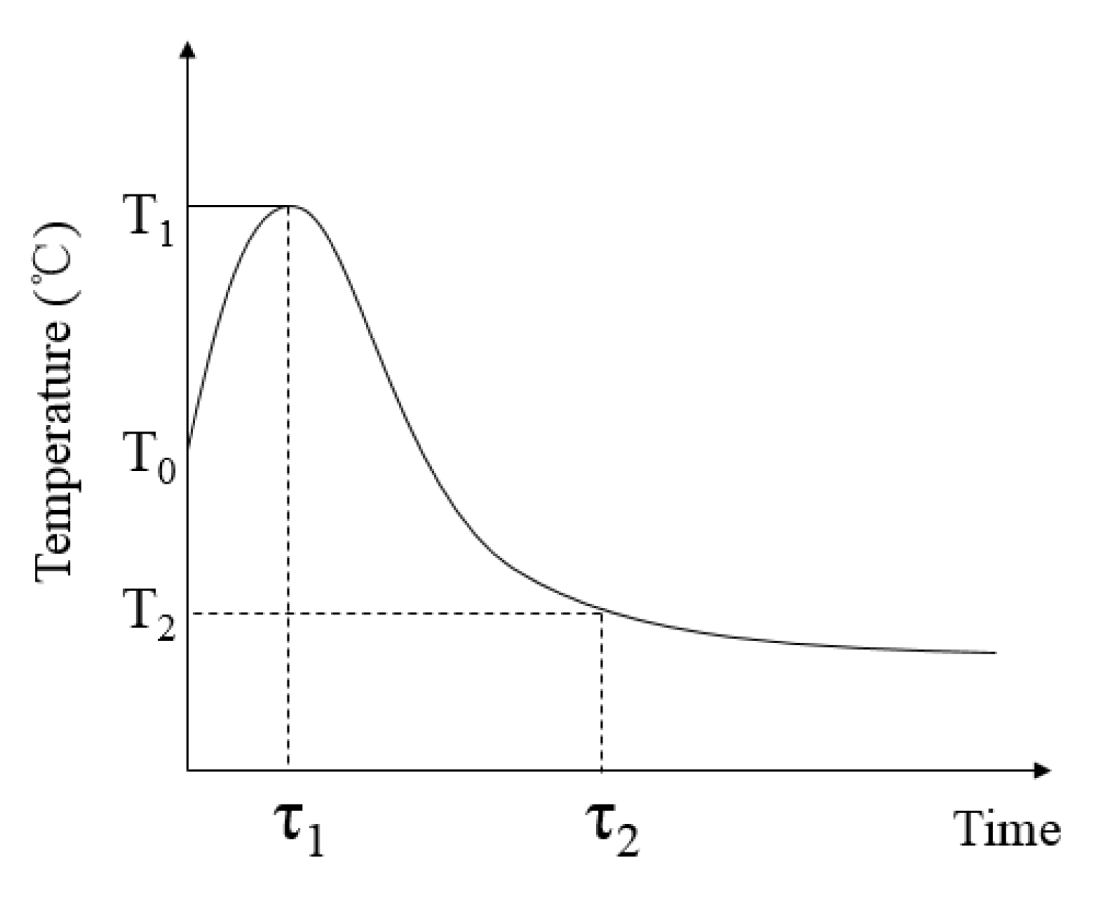
The attenuation delay time τ1 means that the time required for the indoor thermal environment temperature begins to decay from the start of the radiant system. The attenuation delay time reflects the thermal lag speed of the thermal environment. The attenuation delay amplitude refers to the temperature difference between the initial temperature of the indoor thermal environment and the temperature when the indoor thermal environment begins to decay, shown in Figure 4 as T1–T0. This difference reflects the hysteresis degree of the thermal environment.
The stabilization time τ2 refers to the time required for the indoor thermal environment to reach stability. The stabilization time reflects the steady speed of the thermal environment. The steady value T2 means the value when the indoor thermal environment reaches stability.

3. Results and Discussion

3.1. Effect of Supply Water Temperature on Indoor Thermal Environment

3.1.1. Temperature Distribution of Envelope

We measured the temperature of walls, ceiling, and floor when the supply water temperature of the radiant cooling system ranged from 12 °C to 19 °C. In addition, we selected four typical conditions (i.e., 12 °C, 14 °C, 16 °C, and 18 °C) in this study. Figure 5 shows the comparison of the temperature change of envelope over time under different supply water temperatures with two types of radiant cooling terminal. We observed a similar trend of the temperature change of envelope over time in the CTRC and CRC. The surface temperature of the envelope slightly increased first, then decreased gradually, and finally reached a steady state. The envelope temperature variation indicates a thermal delay during the operation of radiant cooling, regardless of the type of radiation terminal used. The structure characteristics of the terminal of radiant cooling present a large thermal resistance compared with the terminal of convective air conditioning. The thermal hysteresis phenomenon of the envelope exists in the initial stage of the cooling room due to the weak heat transfer. Moreover, the temperature of the envelope will continue to rise because of the thermal inertia interference. The surface temperature of the envelope gradually decreases after the system runs for a period of time to increase the cooling capacity of radiant terminal. The surface temperature of the envelope seems to be steady when the thermal balance of the indoor environment occurred.
The steady value of the envelope temperature tends to be different. That is, the temperature of the envelope adjacent to a non-air-conditioned environment (exterior envelope) is higher than that adjacent to an air-conditioned environment (interior envelope). When the indoor thermal environment reaches stability, the maximum difference of exterior and interior envelopes for CTRC and CRC is 0.75 °C and 0.45 °C, respectively. CTRC is characterized by a large diameter and tube spacing compared with CRC. Therefore, the surface temperature of the capillary radiation module is highly uniform because the unit area of the radiant terminal has a large effective cooling area. Meanwhile, the heat exchange between the capillary module and the indoor environment is uniform, which allows high efficiency. In addition, the thermal response characteristics of the envelope appear significantly different from the change of supply water temperature when the two types of radiant cooling modules were used, respectively.

3.1.2. Temperature Distribution of Indoor Air

Results in Figure 6 depict the change of indoor air temperature over time under different supply water temperature with two types of radiant terminal. The results show that during the experiments of room cooling with two kinds of radiation terminal, respectively, the indoor air temperature distribution in the horizontal and vertical directions was uneven. The indoor air temperature difference in the horizontal direction with CTRC was remarkable compared with that of CRC. Moreover, the effect of supply water temperature on the indoor air temperature distribution of CTRC in the horizontal direction was more significant. The radiant cooling modules were installed symmetrically in the experiment, which leads to approximately equal radiation heat transfer between the radiant module and envelope near the window and the door. The influence of the radiant cooling terminal on the uneven distribution of air temperature can be ignored. However, the temperature of the exterior wall was higher than that of the interior wall together with the local heating from the solar radiation through the window. Then, the local air temperature near the window is higher than that near the door because of the dramatic increase in convective heat transfer. Although the indoor air temperature difference in the vertical direction with CRC was remarkable, the temperature difference mainly appeared above 2 m in the room. The air temperature distribution in the personnel activity area was uniform (the height below 2 m). When the supply water temperature is below 16 °C for the CTRC system and below 19 °C for the CRC system, the indoor air temperature below 1.5 m dropped below 27.5 °C. In this case, the design requirements of the indoor thermal environment applied with radiant cooling system can be met [31]. The air temperature difference occurred in a vertical direction due to natural convection. Moreover, the great and uniform heat transfer capacity of the CRC system allows a high cooling efficiency. Although the vertical air temperature distribution of the CRC system is more uneven than that of the CTRC system, the air temperature in the personnel activity area can still meet the thermal comfort requirements. In addition, the supply water temperature has a limited effect on indoor air temperature stratification in the personnel activity area (the height below 2 m). Furthermore, the thermal environment of the personnel activity area with the CRC system is more uniform and the cooling efficiency is higher compared with that of the CTRC system. Furthermore, shading facilities should be installed to reduce the horizontal temperature stratification.

3.2. Thermal Response Characteristics of Envelope

3.2.1. Thermal Response Characteristics of Envelope with CTRC System

Results in Figure 7 depict the thermal response characteristics of the envelope under different supply water temperature when the CTRC system is adopted. Results show that the difference in attenuation delay time and stabilization time of the interior and exterior envelopes decreased at low (below 16 °C), and increased at high supply water temperatures (above 16 °C). The difference is minimal when the supply water temperature is approximately 16 °C. The difference in attenuation delay and temperature stability increases with the increase in supply water temperature. At the initial operation stage of the radiant cooling system, the interior envelope transfers heat from indoor to outdoor because the adjacent rooms are air-conditioned. With the continuous operation of the radiant cooling system, this process gradually weakened until the thermal balance is reached, resulting in a delay in the attenuation of the surface temperature. A low supply water temperature leads to a great radiation heat transfer between the radiant cooling module and the envelope because an exponential relationship exists between radiation heat transfer and surface temperature. In addition, the surface temperature of the envelope changed dramatically with a decrease in supply water temperature. The thermal influence of the radiant cooling system on the envelope is weakened for the significant decrease in radiation heat transfer with the increase in supply water temperature. Therefore, the minimum value for the difference in stabilization time between the interior and exterior envelopes exists with the increase in supply water temperature. Results in Figure 7 show that the temperature attenuation hysteresis and the steady velocity of the envelope are sensitive to a low supply water temperature. The temperature attenuation hysteresis of the envelope can be improved when the supply water temperature is reduced.

3.2.2. Thermal Response Characteristics of Envelope with CRC System

Results in Figure 8 show the thermal response characteristics of the envelope with different supply water temperature using the CRC system. Results show that the difference in attenuation delay time between the interior and exterior envelopes decreases when the supply water temperature increased from 12 °C to 18 °C. Moreover, the difference in attenuation delay amplitude increased with the rise in the supply water temperature. However, the variation of supply water temperature has a limited effect on the difference in stabilization time and steady value of the interior and exterior envelopes. This phenomenon can be explained by the structural characteristics of the CRC system. The radiant cooling terminal has a direct effect on the interior envelope because the adjacent room is air-conditioned. For the exterior envelope exposed to the outdoor or non-air-conditioned environment, the thermal effect of the radiant terminal is dominant under the low supply water temperature. In addition, the outdoor thermal environment dominates with the high supply water temperature. This finding indicates that the attenuation delay amplitude of the exterior envelope is sensitive to the supply water temperature. The attenuation delay time is related to the thermal performance of the envelope, resulting in a significant effect of the supply water temperature on the attenuation delay time of the interior envelope due to the small thermal inertia. Moreover, the cooling capacity of the unit area of the CRC system is larger than that of the CTRC system and the surface temperature of the capillary module is more uniform, which leads to a steady radiation heat transfer between the radiant module and the envelope. The thermal inertia of the capillary radiant terminal makes for the slow thermal response of the envelope at the initial operation stage of the system. With the operation of the system, the temperature fluctuation of the envelope decreases gradually. Results in Figure 8 indicate that the thermal stability and thermal uniformity of the envelope are less sensitive to the supply water temperature.

3.3. Thermal Response Characteristics of Indoor Air

3.3.1. Thermal Response Characteristics of Indoor Air with CTRC System

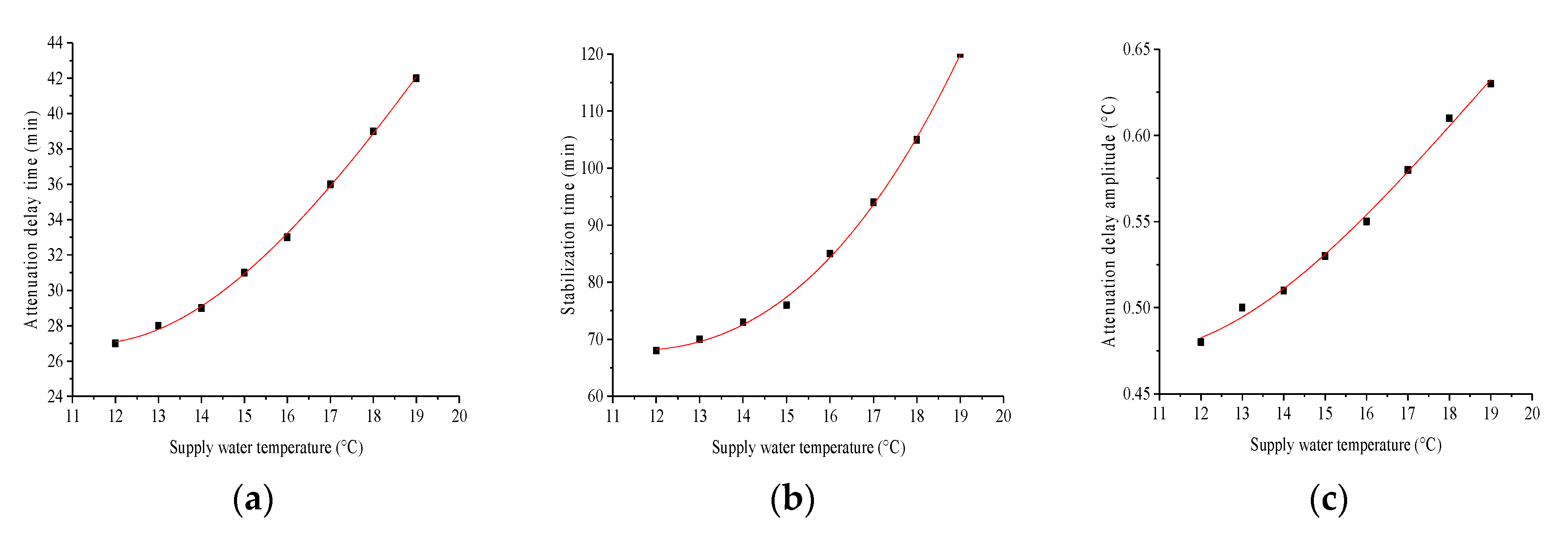
The results in Figure 9 present the change in attenuation delay time, stabilization time and attenuation delay amplitude of indoor air with different supply water temperature using the CTRC system. The results show that attenuation delay time and stabilization time are highly sensitive to a high supply water temperature (above 15 °C). A linear relationship is observed between the attenuation delay amplitude and supply water temperature. The trend observed in Figure 9 can be attributed to the rapid thermal response of the copper tube radiant terminal. The thermal response of the radiation terminal is faster with a low supply water temperature, and the temperature of the envelope reduced rapidly, which improved the attenuation delay of air temperature at the initial stage. In addition, when the radiant cooling system operating with a low supply water temperature, the natural convective heat transfer intensity between the indoor air and the surface increased due to the large temperature difference. Moreover, the discrepancy in the attenuation delay and steady speed of the indoor air marginally changed with the supply water temperature. Furthermore, the thermal response of the indoor air reduced significantly with the high supply water temperature because the heat transfer intensity dramatically decreased. This case indicated that the thermal response of the indoor air under the high supply water temperature is slow and produces an attenuation lag phenomenon at the initial operation stage of the system. The thermal response speed of the air temperature can be improved with the low supply water temperature. However, as the supply water temperature further decreases, the speed of the air temperature stabilization cannot be effectively improved. It can be seen from the Figure 9 that the low supply water temperature (below 15 °C) has a limited effect on the air temperature stabilization time. Therefore, the low supply water temperature will not effectively improve air temperature stability speed. A supply water temperature of 15 °C is advisable for the CTRC system.

3.3.2. Thermal Response Characteristics of Indoor Air with CRC System

The results shown in Figure 10 depict the change in attenuation delay time, stabilization time and attenuation delay amplitude of indoor air with different supply water temperature using the CRC system. The results show a similar trend for the effect of supply water temperature on attenuation delay time, stabilization time and the attenuation delay amplitude of indoor air. The gradient of indoor air thermal response parameter decreases with the increase in the supply water temperature. The threshold of supply water temperature is 16 °C for the change in indoor air thermal response characteristics. One possible explanation is that the structure of the capillary has a large thermal resistance, small pipe diameter and large tube density which enhance the natural convection heat transfer at a low supply water temperature. Section 3.2 shows that the low supply water temperature has a significant effect on the thermal response of the envelope. Therefore, the low supply water temperature also has a significant influence on the indoor air thermal response characteristics. As can be seen in Figure 10, when the supply water temperature changed from 12 °C to 16 °C, the attenuation delay time increases by less than 10 min, the delay increases by approximately 0.1 °C and the temperature stabilization time increases by roughly 35 min. This finding indicates that the indoor air thermal response characteristics are less sensitive to the supply water temperature within that range. Section 3.1 shows that air temperature occupants’ activity area has reached a comfortable standard, so the supply water temperature of 19 °C is an optimal choice for the CRC system. In this case, it not only meets the requirements of indoor comfort, but also has an acceptable thermal response characteristic of indoor air, which is conducive to giving play to the advantages of energy-saving and comfort of the CRC system.

4. Conclusions

Temperature differences occurred among different envelopes when using the modular radiant cooling system in low-energy buildings. When the supply water temperature increased from 12 °C to 19 °C, the temperature difference between the interior and exterior envelope increased for the CTRC system. However, this difference has a limited effect on the CRC system. The temperature difference between the interior and exterior envelope of the CTRC system is more significant than that of CRC for the same supply water temperature. Temperature stratification exists in vertical and horizontal directions of indoor air regardless of using a copper tube or capillary module radiant cooling. The vertical temperature distribution of the CTRC system is more uniform than that of the CRC one. However, the temperature stratification in the active area of the occupant is acceptable and can meet the desired requirements of comfort using the CRC system. Therefore, the effective utilization rate of the cooling capacity of the CRC system is higher than that of the CTRC system.
The thermal response of the envelope is highly sensitive to the low supply water temperature (below 16 °C) using the CTRC system. The low supply water temperature is beneficial to reduce the temperature attenuation hysteresis of the envelope and improve the thermal stability speed. The thermal response of the envelope is highly sensitive to the high supply water temperature (above 16 °C) for the CRC system. The high supply water temperature is beneficial to improve the thermal stability and uniformity of the envelope. The low supply water temperature (below 16 °C) of the CTRC system can improve the thermal stability speed of indoor air. However, when the supply water temperature further decreases, the speed of air temperature stabilization cannot be effectively improved. The improvement in indoor thermal comfort is not significant with the low supply water temperature (below 16 °C) of the CRC system.
Based on the indoor thermal environment comfort and thermal response characteristics, the supply water temperature for the copper tube module radiant cooling system should be 15–16 °C, and 18–19 °C for the capillary module radiant cooling system, to exert the optimal cooling benefit of different radiation terminal structures.

Author Contributions

Conceptualization, Z.L.; methodology, D.Z.; formal analysis, D.Z.; writing—original draft preparation, D.Z.; writing—review and editing, D.Z. and C.L.; supervision, Z.L. All authors have read and agreed to the published version of the manuscript.

Funding

This research was funded by the National Key R&D Program of China for the 13th Five-Year Plan grant number 2017YFC0702600.

Conflicts of Interest

The authors declare no conflict of interest.

References

  1. Fang, H.; Xia, J.; Jiang, Y. Key issues and solutions in a district heating system using low-grade industrial waste heat. Energy 2015, 86, 589–602. [Google Scholar] [CrossRef]
  2. Alalouch, C.; Al-Saadi, S.N.; AlWaer, H.; Al-Khaled, K. Energy saving potential for residential buildings in hot climates: The case of Oman. Sustain. Cities Soc. 2019, 46, 101442. [Google Scholar] [CrossRef]
  3. Li, Z.; Zhang, D.; Chen, X.; Li, C. A comparative study on energy saving and economic efficiency of different cooling terminals based on exergy analysis. J. Build. Eng. 2020, 30, 101224. [Google Scholar] [CrossRef]
  4. Rhee, K.N.; Kim, K.W. A 50 year review of basic and applied research in radiant heating and cooling systems for the built environment. Build. Environ. 2015, 91, 166–190. [Google Scholar] [CrossRef]
  5. Rhee, K.N.; Olesen, B.W.; Kim, K.W. Ten questions about radiant heating and cooling systems. Build. Environ. 2017, 112, 367–381. [Google Scholar] [CrossRef] [Green Version]
  6. Song, D.; Kim, T.; Song, S.; Hwang, S.; Leigh, S.-B. Performance evaluation of a radiant floor cooling system integrated with dehumidified ventilation. Appl. Therm. Eng. 2008, 28, 1299–1311. [Google Scholar] [CrossRef]
  7. Romaní, J.; De Gracia, A.; Cabeza, L.F. Simulation and control of thermally activated building systems (TABS). Energy Build. 2016, 127, 22–42. [Google Scholar] [CrossRef] [Green Version]
  8. Qin, F.; Wang, C.; Feng, L.; Lv, H. Modeling Based on Semi-tensor Product for Radiant Floor Cooling Systems. Procedia Eng. 2017, 205, 3782–3788. [Google Scholar] [CrossRef]
  9. Zakula, T.; Armstrong, P.R.; Norford, L. Advanced cooling technology with thermally activated building surfaces and model predictive control. Energy Build. 2015, 86, 640–650. [Google Scholar] [CrossRef]
  10. Ferkl, L.; Široký, J. Ceiling radiant cooling: Comparison of ARMAX and subspace identification modelling methods. Build. Environ. 2010, 45, 205–212. [Google Scholar] [CrossRef]
  11. Arteconi, A.; Costola, D.; Hoes, P.-J.; Hensen, J. Analysis of control strategies for thermally activated building systems under demand side management mechanisms. Energy Build. 2014, 80, 384–393. [Google Scholar] [CrossRef] [Green Version]
  12. Lehmann, B.; Dorer, V.; Gwerder, M.; Renggli, F.; Todtli, J. Thermally activated building systems (TABS): Energy efficiency as a function of control strategy, hydronic circuit topology and (cold) generation system. Appl. Energy 2011, 88, 180–191. [Google Scholar] [CrossRef]
  13. Gwerder, M.; Lehmann, B.; Todtli, J.; Dorer, V.; Renggli, F. Control of thermally-activated building systems (TABS). Appl. Energy 2008, 85, 565–581. [Google Scholar] [CrossRef]
  14. Olesen, B.W.; Sommer, K.; Düchting, B. Control of Slab Heating and Cooling Systems Studied by Dynamic Computer Simulations. Ashrae Trans. 2002, 108, 698–707. [Google Scholar]
  15. Yin, Y.; Wang, R.; Zhai, X.; Ishugah, T. Experimental investigation on the heat transfer performance and water condensation phenomenon of radiant cooling panels. Build. Environ. 2014, 71, 15–23. [Google Scholar] [CrossRef]
  16. Novoselac, A.; Srebric, J. A critical review on the performance and design of combined cooled ceiling and displacement ventilation systems. Energy Build. 2002, 34, 497–509. [Google Scholar] [CrossRef]
  17. Kim, K.W.; Olesen, B.W. Radiant Heating & Cooling Systems: Part 2. Ashrae J. 2015, 57, 28–37. [Google Scholar]
  18. Ryu, S.; Lim, J.-H.; Yeo, M.-S.; Kim, K.-W. A Study on the Control Methods for Radiant Floor Heating and Cooling System in Residential Building. ASHRAE Trans. 2004, 110, 106–116. [Google Scholar]
  19. Cho, S.-H.; Zaheer-Uddin, M. An experimental study of multiple parameter switching control for radiant floor heating systems. Energy 1999, 24, 433–444. [Google Scholar] [CrossRef]
  20. Lim, J.-H.; Jo, J.-H.; Kim, Y.-Y.; Yeo, M.-S.; Kim, K.-W. Application of the control methods for radiant floor cooling system in residential buildings. Build. Environ. 2006, 41, 60–73. [Google Scholar] [CrossRef]
  21. Rhee, K.; Ryu, S.; Yeo, M.; Kim, K. Simulation study on hydronic balancing to improve individual room control for radiant floor heating system. Build. Serv. Eng. Res. Technol. 2010, 31, 57–73. [Google Scholar] [CrossRef]
  22. Olesen, B.W. Radiant floor heating in theory and practice. Ashrae J. 2002, 44, 19–26. [Google Scholar]
  23. Zhao, K.; Liu, X.-H.; Jiang, Y. On-site measured performance of a radiant floor cooling/heating system in Xi’an Xianyang International Airport. Sol. Energy 2014, 108, 274–286. [Google Scholar] [CrossRef]
  24. Lehmann, B.; Dorer, V.; Koschenz, M. Application range of thermally activated building systems tabs. Energy Build. 2007, 39, 593–598. [Google Scholar] [CrossRef]
  25. Xie, D.; Wang, Y.; Wang, H.; Mo, S.; Liao, M. Numerical analysis of temperature non-uniformity and cooling capacity for capillary ceiling radiant cooling panel. Renew. Energy 2016, 87, 1154–1161. [Google Scholar] [CrossRef]
  26. Feng, J.; Schiavon, S.; Bauman, F. New method for the design of radiant floor cooling systems with solar radiation. Energy Build. 2016, 125, 9–18. [Google Scholar] [CrossRef] [Green Version]
  27. Seo, J.-M.; Song, D.; Lee, K.H. Possibility of coupling outdoor air cooling and radiant floor cooling under hot and humid climate conditions. Energy Build. 2014, 81, 219–226. [Google Scholar] [CrossRef]
  28. Chiang, W.-H.; Wang, C.-Y.; Huang, J.-S. Evaluation of cooling ceiling and mechanical ventilation systems on thermal comfort using CFD study in an office for subtropical region. Build. Environ. 2012, 48, 113–127. [Google Scholar] [CrossRef]
  29. Le Dréau, J.; Heiselberg, P. Sensitivity analysis of the thermal performance of radiant and convective terminals for cooling buildings. Energy Build. 2014, 82, 482–491. [Google Scholar] [CrossRef]
  30. Ministry of Housing and Urban-Rural Development of PR China. Technical Standard for Nearly Zero Energy Buildings; China Architecture & Building Press: Beijing, China, 2019.
  31. ISO. ISO 7730—Ergonomics of the Thermal Environment-Analytical Determination and Interpretation of Thermal Comfort Using Calculation of the PMV and PPD Indices and Local Thermal Comfort Criteria; International Standard Organization: Geneva, Switzerland, 2005. [Google Scholar]
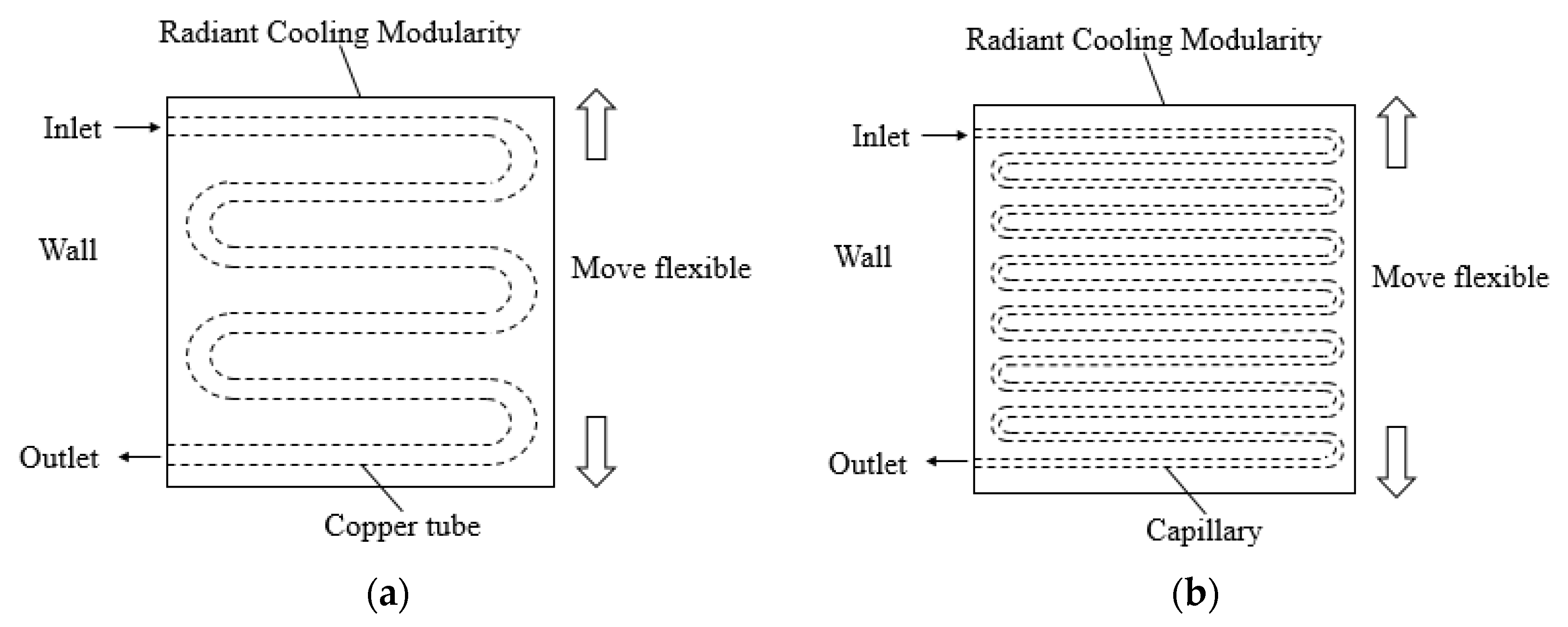
Figure 1. The schematic of the modular radiant terminal: (a) The copper tube module radiant terminal; (b) The capillary module radiant terminal.
Energies 13 05012 g001
Figure 2. (a) Modular radiant terminal; (b) Field test.
Energies 13 05012 g002
Figure 3. Schematic diagram of the experimental test system.
Energies 13 05012 g003
Figure 4. Thermal response of indoor environment.
Energies 13 05012 g004
Figure 5. The temperature change of envelope over time under different supply water temperature with CTRC ((ad) for 12 °C, 14 °C, 16 °C and 18 °C, respectively) and CRC ((eh) for 12 °C, 14 °C, 16 °C and 18 °C, respectively). Copper tube radiant cooling (CTRC), capillary radiant cooling (CRC).
Energies 13 05012 g005
Figure 6. The indoor air temperature distributions under different supply water temperature with CTRC ((ad) for 12 °C, 14 °C, 16 °C and 18 °C, respectively) and CRC ((eh) for 12 °C, 14 °C, 16 °C and 18 °C, respectively).
Energies 13 05012 g006
Figure 7. Change in stabilization time (a), steady value (b), attenuation delay time (c) and attenuation delay amplitude (d) of the envelope with supply water temperature for the CTRC system.
Energies 13 05012 g007
Figure 8. Change in stabilization time (a), steady value (b), attenuation delay time (c) and attenuation delay amplitude (d) of the envelope with supply water temperature for CRC system.
Energies 13 05012 g008
Figure 9. Change in attenuation delay time (a), stabilization time (b) and attenuation delay amplitude (c) of indoor air with different supply water temperature of the CTRC system.
Energies 13 05012 g009
Figure 10. Change of attenuation delay time (a), stabilization time (b) and attenuation delay amplitude (c) of indoor air with different supply water temperature of CRC system.
Energies 13 05012 g010
Table 1. Tests cases.
CaseTerminal TypeOperation ScheduleSupply Water Temperature (°C)
1Copper tube/Capillary08:00–12:0012
2Copper tube/Capillary08:00–12:0013
3Copper tube/Capillary08:00–12:0014
4Copper tube/Capillary08:00–12:0015
5Copper tube/Capillary08:00–12:0016
6Copper tube/Capillary08:00–12:0017
7Copper tube/Capillary08:00–12:0018
8Copper tube/Capillary08:00–12:0019