1. Introduction
Nowadays, the deployment of Electric buses solutions for transportation has become a priority around the word to handle environmental concerns [
1]. This concept consists of the electrification of classical diesel engine chains by eco-friendly sources, such as fuel-cells and batteries. The PMSMis perceived as a competitive candidate for high-performance automotive applications. This attention is partly due to its many attributes, such as lofty power density, big torque to inertia rate, and high performance [
2,
3,
4]. In order to enhance the operating range of PMSM and to extend its scope of applications, many research works have addressed the aforementioned drawbacks, especially speed ripples at low speed operation issue. Indeed, the relevant reports have identified two ways to overcome torque ripples at low speed operation in PMSM; machine design improvement [
3,
5] and advanced control techniques [
6,
7,
8]. With regard of motor design improvements, the proposed solutions are not cost effective and require complex set up procedures [
3]. While active control based techniques used to deal with the non ideal characteristics of PMSM are cost effective and just require handling the excitationschemes. Several active control based approaches have been used to minimize harmonic contents in order to get a smooth torque at low speed operation [
9,
10]. The current waveform profiling control method is the widely and commonly used approach for torque ripple minimization at low speed operation [
2]. All the studied schemes are fundamentally based on the injection of selected harmonic components to achieve desired pulsating torque elimination [
6,
10]. Despite their effectiveness in torque ripple minimization, they require a strong computational effort and are not suitable for practical online implementation.
Today there are basically two types of instantaneous controls of PMSM drives: Field Oriented Control (FOC) group and Direct Torque Control (DTC) group. Compared with the FOC group, the DTC has numerous benefits, such as lower parameter dependency, simpler digital implementation, and faster dynamic torque response [
7,
11]. In the case of classical DTC, the appropriate voltage vectors are chosen by the errors of torque and flux linkage without need to coordinate transformation and current controller. In this scheme, the use of a switching table and hysteresis regulators is efficient to carry out the DTC. Although DTC is getting more and more competitive compared to the FOC approach, it too has a few disadvantages, such as variable switching frequency, flux and torque undulation and high sampling frequency [
11]. So, the main challenge that PMSM drives still face is how to effectively reduce their torque ripple, particularly at low speed operation. Therefore, the way of minimizing torque ripple becomes the main research subject in DTC techniques [
7,
8,
11,
12].
In this context, and thanks to its advantages, such as low torque ripple, constant switching frequency and excellent DC bus utilization, the DTC associated to Space Vector Modulator (SVM) is widely recognized as valuable solution since it can create more precise and suitable torque and stator flux [
6].
The Predictive Torque Control-Pulse Width Modulation (PTC-PWM) has been introduced as a serious rival to DTC [
6]. Predictive Torque Control (PTC) has been extensively applied to electric drive control tanks for the development of high speed DSPs [
7,
13,
14]. In this group, the future action of the drive is predicted using a discrete-time PMSM model. The prediction results are assessed using a predefined fitness function and the reference voltage space vector in accordance to the least cost is applied to the PMSM via pulse width modulator. In [
7], the authors proposed a cascade MPC to improve the speed control of a machine with Speed Ripple (SR) cancellationusing two MPC structures. As a result, the effects of disturbance nonlinearities, parameter uncertainties and speed ripple at a steady state are reduced. Additionally, in [
15], a repetitive predictive controller is investigated in PMSM drive and minimum speed ripple due to the effect of measurements can be achieved using this approach. A discrete time state-space model-based PTC is described in [
7] for PMSMs; to attain exact torque control, the developed prediction topology employs incremental changes in the stator flux and current, along with voltage vectors. The effectiveness of their torque ripple compensation method was demonstrated by experimental results which show dynamic torque response, minimum torque ripples and quasi-sinusoidal stator current. By synchronous improvement of voltage vector and duty cycle, an improved PTC was proposed in [
16]. Thus, a far superior steady-state personification in terms of torque ripple can be gained compared to conventional PTC. Another version of PTC was investigated in [
8] where the proposed strategy changes the time duration of the output voltage, which leads not only to a fast dynamic, but also to an effective reduction in torque ripple. In the study presented in [
17], a PTC was proposed to achieve low ripples in the steady-state, where the amplitude, phase and time execution of the voltage applied to PMSM are properly optimized. Another application in [
18], a Lyapunov-based PTC for PMSM is proposed. The Lyapunov function is used to estimate the duty cycle of each voltage vector. In [
18], three DTC-based approaches, including PTC for PMSM, were critically assessed under several control performance criteria. This study concludes that PTC can accomplish reduced switching frequency and torque ripple compared to DTC beneath the same sampling frequency.
Intelligent controls, based on artificial intelligence, has proven its effectiveness and can act better than conventional adaptive controls in electric drives. In [
19], a neural network based controller is used for ripple minimization. In this work, the quadrature inductance is modeled off-line, agreeing to quadrature stator current where weights are initially taken as little random values and adjusted according to the model reference control algorithm. All the aforementioned predictive approaches have in common an optimization problem resulting from the PTC formulation, which must be somehow solved. According to how the optimization problem is solved—on-line or off-line—PTC can be classified as implicit or explicit. In contrast to the explicit PTC, in the implicit one, the optimization problem must be solved in real time, running conditions which involves the use of fast numerical solvers. In [
20], a cost function based optimization algorithm is presented as an efficient algorithm to solve the PTC optimization problem in real-time on embedded hardware. In [
21], an on-line PTC method for a PMSM motor was proposed and an embedded quadratic programming solver is used to solve the predictive control problem. In order to confirm the feasibility of the proposed strategy, its performance was assessed in Processor In the Loop (PIL) experiments.
In spite of the effective performance of PTC methods, they are based on system model knowledge, and thereby should be sensitive to large model parameters variation. Indeed, in vehicular applications, drives systems are subject to unknown disturbances—e.g., time-varying load, friction forces, and particularly effects of un-modeled phenomena at low-speed running. In this way, the paper presents an efficient torque-controller based on an optimization strategy without requiring knowledge of the framework parameters. The proposed PTC control approach is based on GWO, which is also motivated by the advantage of GWO method for determining the minimum fitness function with attractive characteristics, such as quick convergence and few adjustment gains. GWO is a recently heuristic strategy to handle complicated optimization problems [
22,
23]. It reproduces the social hierarchy and chasing behavior of grey wolves—the significant strides of grey wolves chasing, such as searching for prey, circling, and assaulting. The method moves as the wolves bunch toward prey by refreshing the location vector, which is an average of the better situation of the group. As explored in [
22], this algorithm presents a few preferences compared to other heuristic algorithms, such as Particle Swarm Optimization (PSO) in terms of low time execution, high-resolution accuracy, convergence independence of starting conditions and its capacity to deal with local minima. This usefulness is reflected in several works in power systems where optimization is necessary [
24,
25,
26,
27,
28,
29].
Thus, as to confirm the feasibility of our strategy, its performance was evaluated in experiments. In the present work, a new control strategy based on GWO strategy is proposed to guarantee torque smoothness at the low speed running of PMSM. The key idea is to incorporate the benefit of the speedy optimization process of the GWO to discover the ideal trajectory of the controls which diminish the fitness function. For this aim, the proposed fitness function is composed by torque and stator flux—these fingerprints present the intrinsic electromagnetic characteristics of the machine. This choice allows for setting high effective bandwidth, which facilitates speed pulsation rejection and gives the desired performances concerning the torque tracking.
This paper is organized as follows: A description of the studied system and its control are presented in
Section 2.
Section 3 introduces the proposed torque approach. To this end, the cost function considering flux and torque errors is defined and the design principle of the proposed GW algorithm is provided.
Section 4 presents simulation part and investigates how the objective function parameters are selected. Then, in
Section 5 experimental results are presented and reflect the viability of the proposed control approach. Eventually,
Section 6 epitomizes the contributions of this paper.
2. System Description
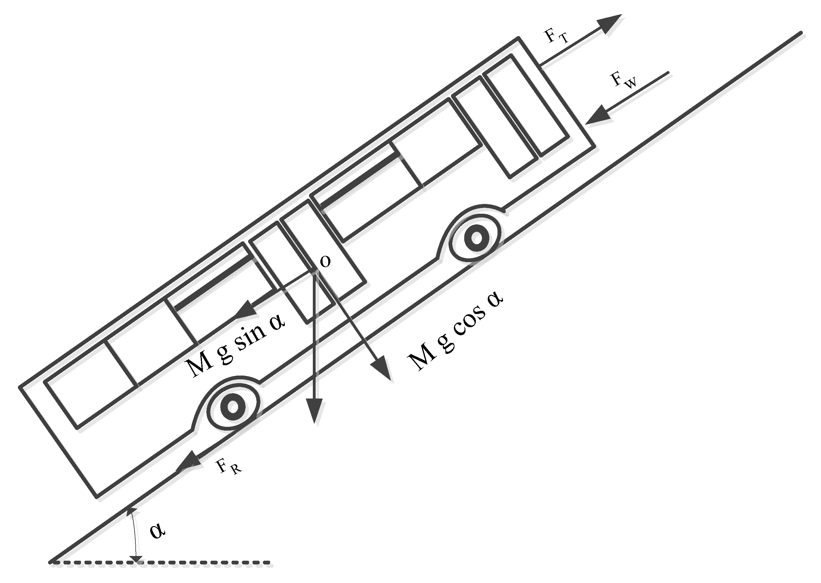
The designing of EB entail the physics fundamental concept, the Newton’s second law of motion. The EB maneuver can be wholly defined by evaluating the thrust forces applied to it in the operational direction. The different forces applied and resisting in the EB, when it is moving in an uphill direction are shown in
Figure 1. There are forces which act on the EB in the uphill direction of movement and forces which resist the EB movement. The force, due to which the EB can move forward, are known as tractive force. (
). There exist some opposite direction forces that are put into effect on the EB when moving on a certain land profile—the rolling resistance force (
), the aerodynamic drag (
), the grading or uphill force (
) and the acceleration force. The fundamental principle of the vehicle dynamics, expressed in [
27,
30], are as follows:
where,
m is the mass of the EB (kg);
g is the gravitational constant (m/s
);
is the driving velocity of the EB;
is the rolling resistance;
is the air density (kg/m
);
A is the frontal area of EB;
is the coefficient of drag;
is the climb angle.
The total power requested by the wheels of the EB or the total power required to propel the vehicle is expressed in the equation below:
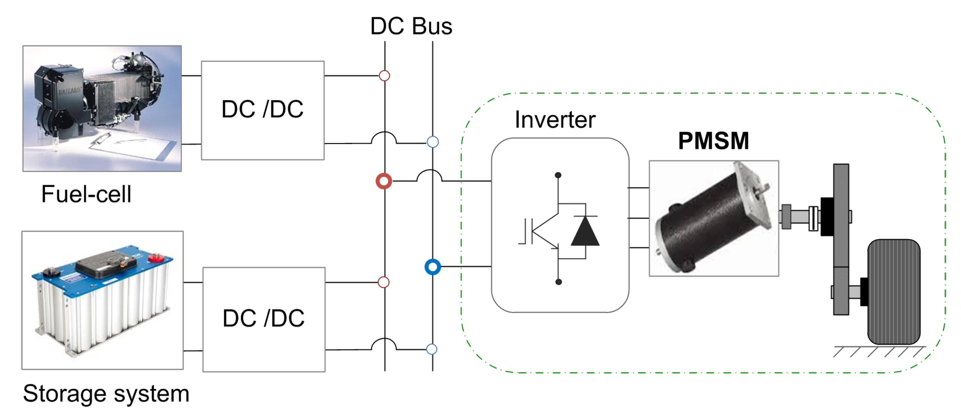
Figure 2 illustrates a typical circuit representation of an BE, wherein fuel cells (energy source) and super capacitors (power source) are connected to the common Direct current (DC) sources via DC/DC converters. While the energy source ensures the steady state operation, the power source is attached to the capacitor-link through bidirectional converter to supply the peak power demand and to keep the capacitor voltage fixed. The motor drive includes a three-phase inverter, PMSM and the coupling load. In this work, the study is focused on the drive side where the capacitor-link is supposed as a voltage source (constant) and the load effect is emulated by a DC generator.
The modeling of the PMSM expressed in the Park’s reference frame is given below:
where
is the voltage of stator vector,
is the current of stator vector,
is the flux of stator,
is the resistance of stator,
is the electrical speed of rotor,
p is the number of the pole pairs,
the angular speed and
is a coupling matrix between d and q.
The flux of stator is expressed in the equation below:
where
is the inductance of stator and
is the Magnetic Flux.
The electromagnetic torque can be written as in Equation (
5).
The formula for motion is in Equation (
6).
where
is the resistance torque,
is the frictional factor and
J is the mechanical moment of inertia.
4. Simulation Results
In this section, the objective function parameters are selected through simulations under Matlab/Simulink software. The proposed selection criterion is based on torque ripple reduction at steady state operation when the system is subject to non-sinusoidal flux density distribution. The system parameters are recorded in
Table 1.
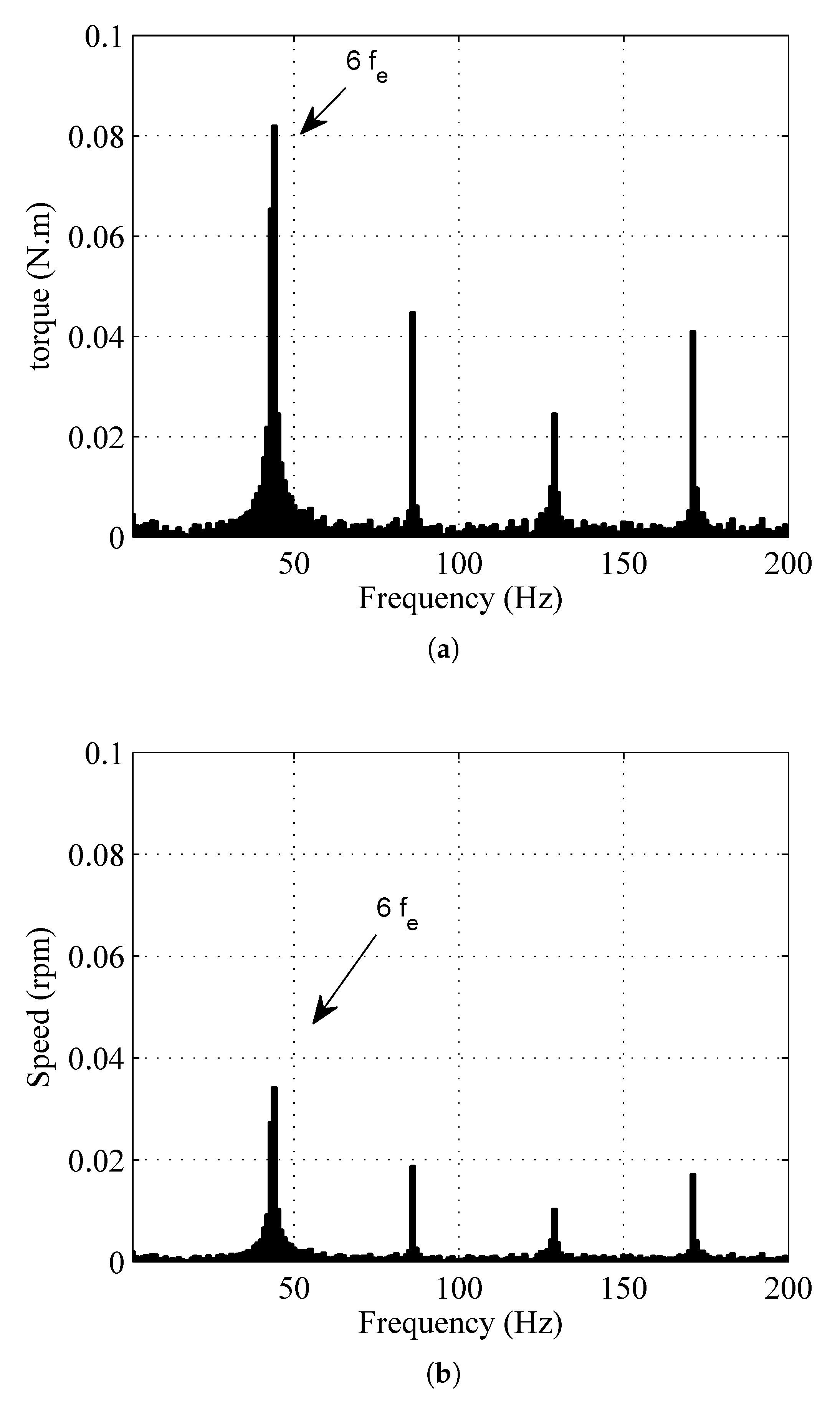
The corresponding torque harmonics show up as the sixth, twelfth and different products of the sixth harmonics [
32,
33], and can be calculated by:
where
is the amplitude of harmonics (multiple sixth).
The 6th, 12th, 18th and 24th flux harmonics are induced in the torque and are chosen equally, respectively, to 7%, 3%, 2% and 1% of the rated torque (
). The system parameters are given in
Table 1.
In this scenario, the torque reference is set to its nominal value under a speed of 100 rpm. The parameters of the fitness function are changed consecutively and the corresponding
is expressed by:
where
m is the number of points and
is the torque reference.
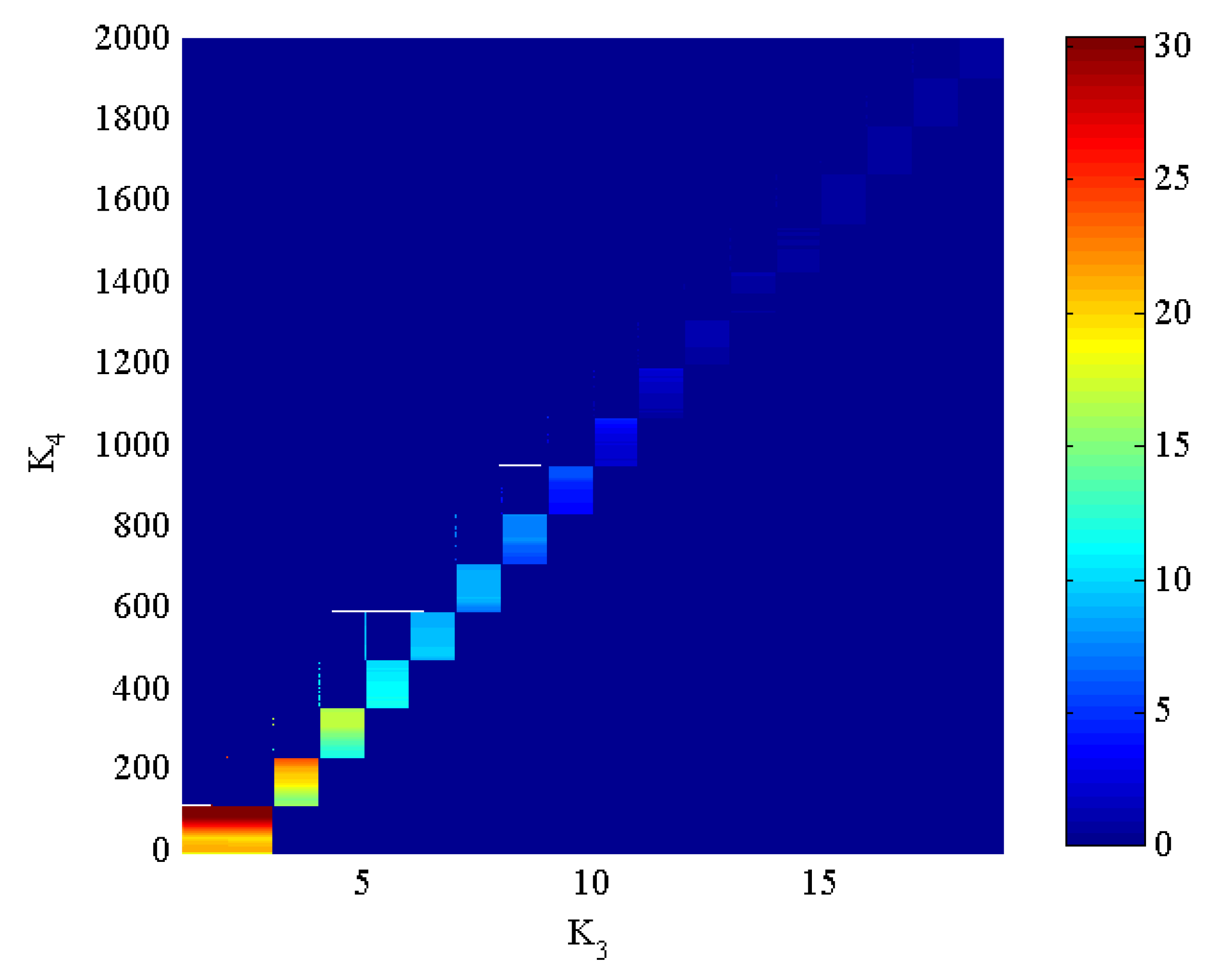
Figure 5 illustrates the influence of the parameters of the objective function
on the torque ripple rate
. As an indicator, with the color change from blue to red, there is an increasing influence on the torque ripple amplitude. In this test, parameters
and
are changed, respectively, from 0 to 20 and 0 to 2000. It very well may be seen that the torque ripple
can be minimized for infinity of solutions (blue zone) and the best choice also depends on the system performance under dynamic operation.
As a result of the previous test, parameters ( and ) are directly related to the resulting torque ripple amplitude. These parameters are set to: = 11 and = 0.01 which satisfy a fast time response without overshoot under stepped torque and particularly a reduced torque ripple at steady-state operation.
Notices that parameters and of the objective function do not influence the torque ripple, which means that the control of the torque is decoupled from the flux. The gains , are set to = 1.5 and = 0.5 which ensure the flux tracking task.
To examine the impact of the parameters choice on the system execution, the following simulation tests are conducted for two parameters sets:
- -
Case (1), by a poor choice of the parameters which are in the yellow zone of
Figure 3. For this, parameters
and
are chosen equal to:
= 7.5 and
= 530.
- -
Case (2), by considering the best objective function parameters.
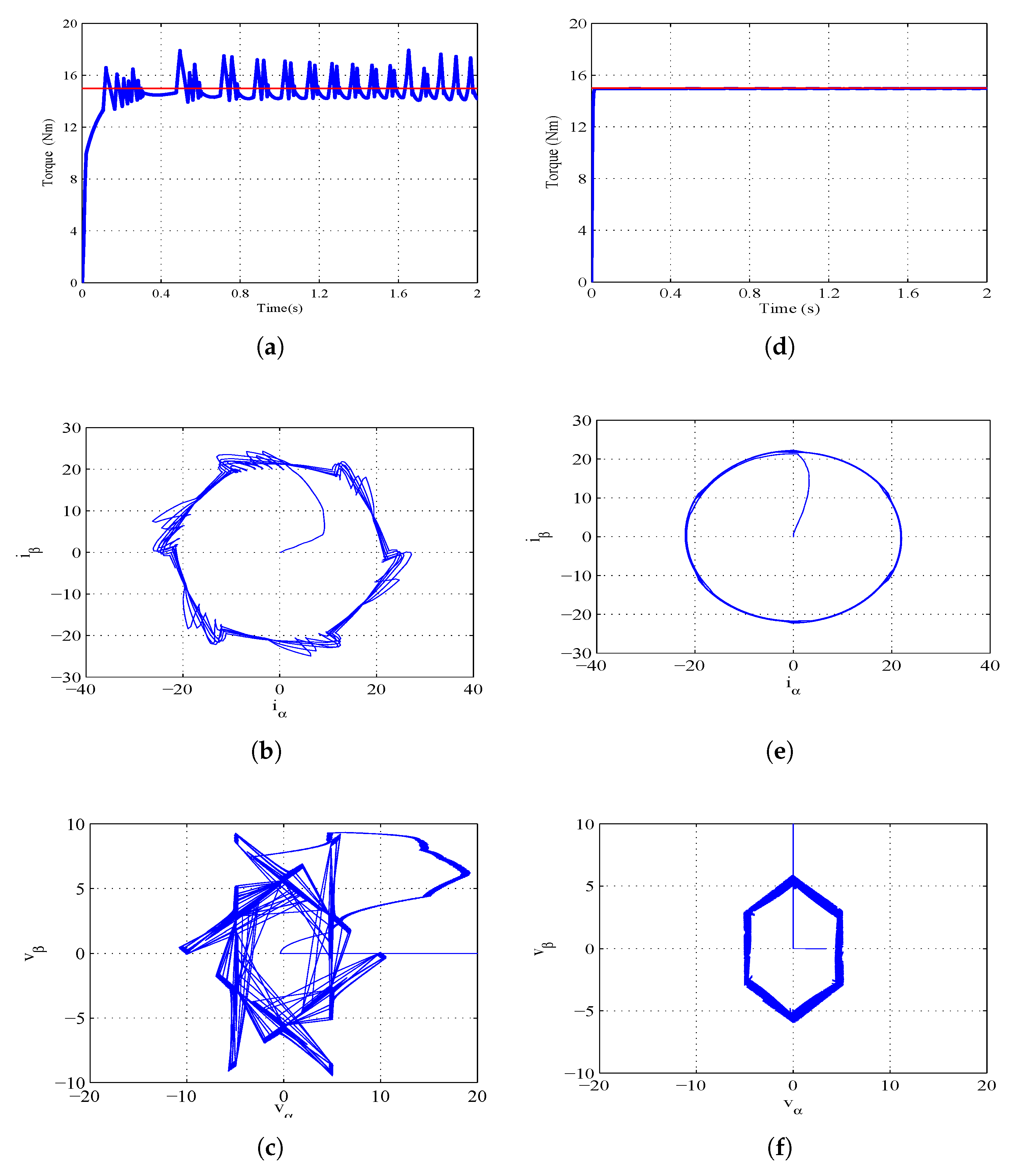
Figure 6 shows the system response under a torque reference of 15 Nm. In this test the torque response, the respective Concordia components of the stator currents, and the input control voltages are highlighted for the two considered parameters sets.
Figure 6a,d illustrate that the torque response when the best objective function parameters are applied (
Figure 6d) follows its reference trajectory with a smoother torque evolution.
Figure 6b,e illustrate the corresponding trajectories of the stator currents in Concordia coordinates for the two considered parameter sets. With the best objective function parameters, the currents follow circular trajectories which means that the resulting
current waveforms are sinusoidal. To investigate the input control behavior under the same test,
Figure 6c,f show the respective trajectories of the input control voltages in Concordia coordinates. From this result, it can be seen that the GW algorithm with the best objective function parameters allows generating minimal input control trajectories and it can be noted that the control efforts are well distributed over the six sector of the PWM.
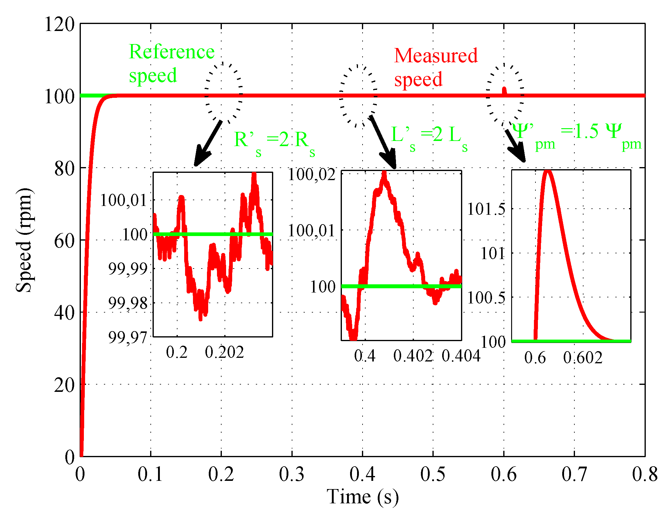
Figure 7 shows the speed response in time domain at 100 rpm under parametric variations. The figure is illustrated in three sequences, respectively: [0.2 to 0.4 s] the stator resistance increase of 100%, between [0.4 to 0.6 s] the stator inductance increase of 100% and between [0.6 to 0.8 s] the stator flux increase of 50%. It is demonstrated that GWO-PTC approaches can endure large parametric variations and, at the same time, maintain good vehicle performance. It can be noticed that the GWO control design does not depend on model parameter knowledge (free-model controller).
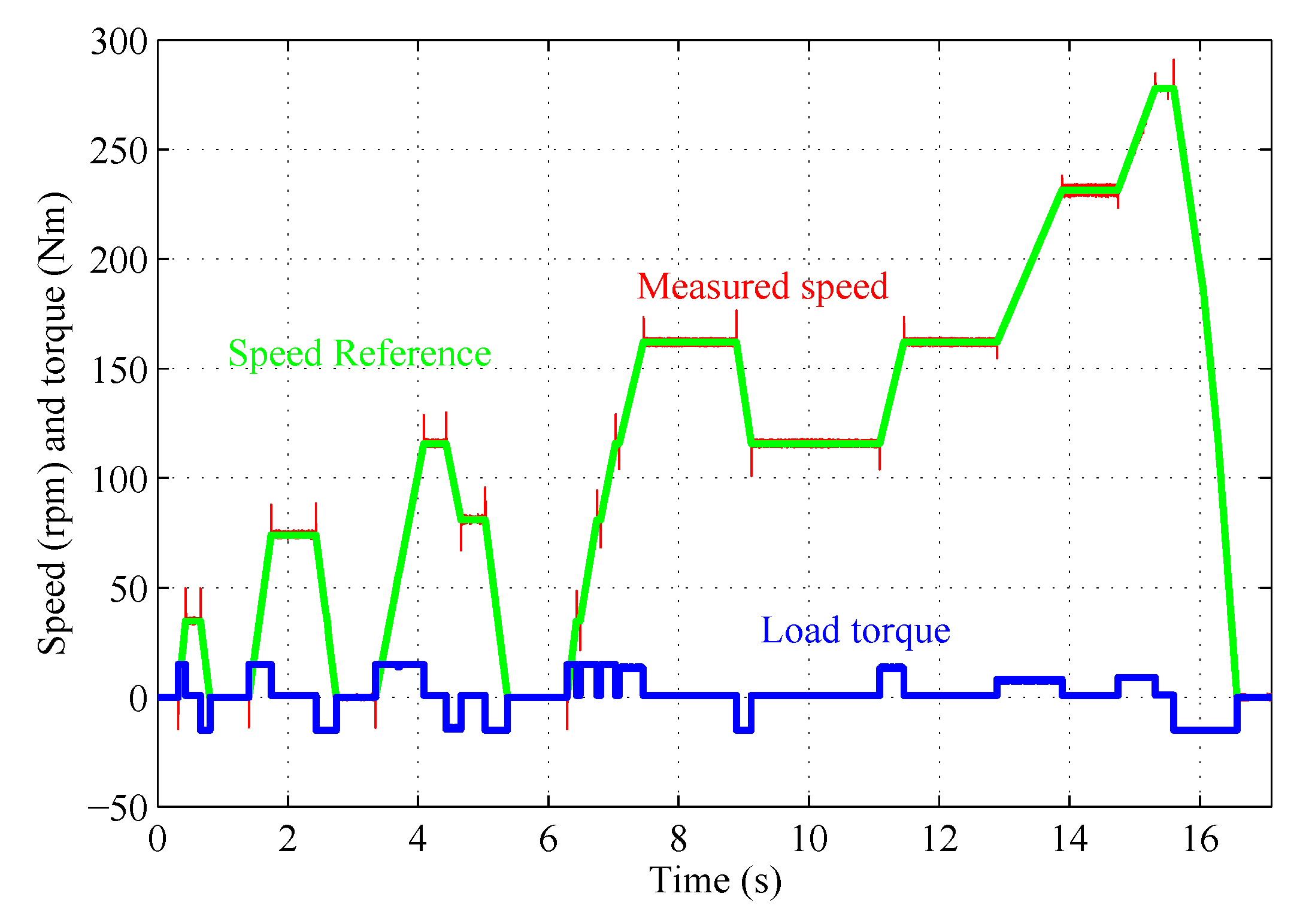
To evaluate the electric Bus dynamic performances, the bus speed and Load torque are illustrated in
Figure 8. For that purpose, the speed reference changes during the proposed cycle under torque change.
6. Comparison between DTC-PI and GWO Controllers for Speed Control
To highlight the advancement of the proposed strategy, a comparison with classical DTC based on a PI regulator is proposed. The design method for the DTC-PI controller is described in [
27].
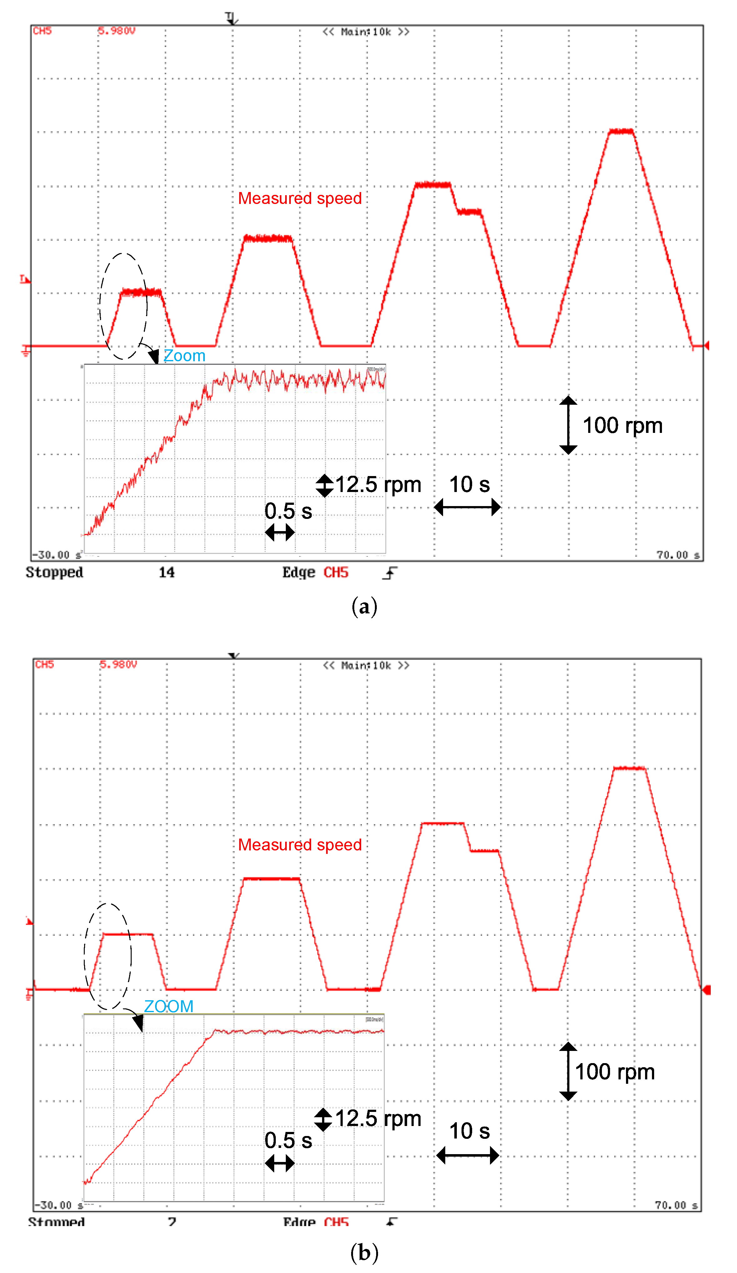
Figure 13a,b, displays the Motor behavior with a DTC-PI and the GWO strategy when the bus speed reference changes during the proposed cycle. The speed ripple factor (SRF) values of the DTC-PI and the proposed approach for diverse speed values are shown in
Figure 14. From this result, the SRF evolution indicates that the proposed approach decreases the speed ripples by a factor of more than 3.75.
In summary, from the tests presented in this section, it can be stated that employing the GWO-PTC allows for obtaining a high-performance control with a smooth-time evolution of the torque and the speed. From the implementation side, the time duration for the compilation of the proposed strategy is found to utilize one of the timers of the dSPACE DS1103 PPC.
The treatment turnaround time within the ControlDesk of the complete proposed strategy counting the park transformation (currents), speed calculation (from the resolver), speed reference generator and the proposed GW controller is 46.3 s whose 39.5 s were used to implement the proposed control. In addition, the algorithm is coded in C language, and based on the available powerful control cards (DSP, FPGA, dsPIC...), the treatment time and CPU utilization is not influenced much by the execution of the proposed method.


