Article

Thin Solid Film Electrolyte and Its Impact on Electrode Polarization in Solid Oxide Fuel Cells Studied by Three-Dimensional Microstructure-Scale Numerical Simulation

1
Department of Fundamental Research in Energy Engineering, AGH University of Science and Technology, 30-059 Krakow, Poland
2
Department of Machinery and Control Systems, Shibaura Institute of Technology, 135-8548 Tokyo, Japan
*
Author to whom correspondence should be addressed.
These authors contributed equally to this work.
Energies 2020, 13(19), 5127; https://doi.org/10.3390/en13195127
Submission received: 31 August 2020 / Revised: 24 September 2020 / Accepted: 25 September 2020 / Published: 1 October 2020
(This article belongs to the Special Issue Electrocatalysts for Fuel Cells and Hydrogen Production)

Abstract

:
In this work, a three-dimensional microstructure-scale model of a Solid Oxide Fuel Cell’s Positive-Electrolyte-Negative assembly is applied for the purpose of investigating the impact of decreasing the electrolyte thickness on the magnitude, and the composition of electrochemical losses generated within the cell. Focused-Ion-Beam Scanning Electron Microscopy reconstructions are used to construct a computational domain, in which charge transport equations are solved. Butler–Volmer model is used to compute local reaction rates, and empirical relationships are used to obtain local conductivities. The results point towards three-dimensional nature of transport phenomena in thin electrolytes, and electrode-electrolyte interfaces.

Graphical Abstract

1. Introduction

As highly efficient energy conversion devices, capable of converting the chemical energy of fuels, directly into electrical energy, Solid Oxide Fuel Cells (SOFCs) have received much interest from the contemporary scientific community [1,2,3]. One major source of thermodynamic losses generated in an SOFC device is the resistance to the conduction of oxide ions in the ceramic phase of the cell. Thus, it is usually beneficial from a thermodynamic standpoint to decrease the thickness of the electrolyte. Fabrication methods, such as thermal spray, chemical vapor deposition, physical !vapor deposition or pulsed laser deposition allow introducing electrolytic films thinner than 10   μ m (as thin as 1   μ m ) [4,5]. Another interesting technique, known as Plasma-Enhanced Atomic Layer Deposition has allowed fabrication of electrolytes thinner than 0.1   μ m . A number of research teams have managed to manufacture working anode-supported SOFC cells with electrolytes as thin as 10   n m , close to the theoretical limit related to dielectric breakdown strength [6]. Baek et al. [6] achieved such low thickness by applying freestanding electrolyte membranes, manufactured using silicon micromachining techniques. Nonetheless, cells with such a thin electrolyte face a number of problems, including durability issues, such as cracks and pinholes, as well as local irregularities stemming from the grain shape [6].
The understanding of the impact of local microstructure inhomogeneities may be improved through the application of a three-dimensional, pore-scale model of charge transport phenomena. In a non-continuous model of a porous electrode, each node within the computational domain is assigned a specific transport function equivalent to the transport function of the corresponding phase within the porous ceramic-metal electrode. The required digital distribution of phases within the microstructure may be obtained using statistical modeling, or three-dimensional reconstructions of a real electrode, obtained using nanotomography. The latter approach has been made possible by the application of Focused Ion Beam Scanning Electron Microscopy (FIB-SEM) to analyze SOFC electrodes, starting with the ground-breaking works by Wilson et al. [7]. In FIB-SEM nanotomography, layers of sample are removed using a Focused Ion Beam. Subsequently, the uncovered cross-sections are imaged using a scanning electron microscope. A non-continuous electrode model was applied in works by Suzue et al. [8] (for a stochastic reconstruction), Shikazono et al. [9], Kanno et al. [10], Kishimoto et al. [11] Carraro et al. [12] and others.
So far, modeling efforts regarding the impact of electrolyte thickness on electrochemical performance have been relatively sparse, as most works focus on the thermo-mechanical properties of the device [13,14]. A study by Park et al. [15] involved a continuous-electrode, cell-scale model of an SOFC unit cell, including cases with electrolyte thickness ranging from 80   μ m to 100   μ m . Despite the sensitivity to local microstructure irregularities, as well as the potential to introduce hierarchical microstructures, and mesoscale electrode-electrolyte interface structures [16], the efforts to model electrochemical transport phenomena at microstructure scale have been rare. Iwai et al. [17] used a pore-scale model with non-continuous phase distribution to compare loss generation for several electrolyte thicknesses ranging from 1   μ m to 10   μ m , demonstrating increase in standard deviation of current densities within electrolytes thinner than 5   μ m . Additionally, some influence of cathodic grain size was predicted by the model. Kishimoto et al. [18] furthered this analysis to discuss the impact of fabricating a grooved electrolyte.
The literature survey unravels the knowledge gap and the necessity to investigate the impact of thin electrolyte on microstructure-scale potential distributions in an SOFC. The purpose of the research described in this work is to apply a microstructure-scale, non-continuous model to analyze the impact of cross-electrolyte effects on the performance of an SOFC positive-electrolyte-negative (PEN) assembly more extensively. The cross-electrode interactions are present if there exists a difference between the performance predicted by a model which assumes uniform current flow through the electrolyte, and the model in which no such assumption is made. Previously we have constructed and validated a model of this type, using it for the purpose of analyzing heterogeneity [19,20], and aging phenomena [21]. However, in these studies, the electrodes were investigated individually. In our current paper, we present a model, where the computational domain includes both the anode, and the cathode. The decomposition of thermodynamic losses is presented alongside with distribution of charge transfer and electric potential within a cell. A number of Positive-Electrolyte-Negative assembly simulations with different electrolyte thicknesses are studied, and effects of cross-electrode phenomena are assessed in particular.

2. Mathematical and Numerical Model
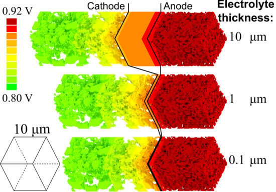
The modeled chemical reaction includes the half reactions of the combustion of hydrogen:
2 H 2 + O 2 2 H 2 O O 2 + 2 e 2 O 2 on the anode , 2 H 2 + 2 O 2 2 H 2 O + 2 e on the cathode .
The charge transfer model is based on the Poisson conservation with the source term being the local, volumetric charge transfer rate:
· σ j ϕ j = i , j = ion ( O 2 ) i , j = el ( e ) ,
where ϕ el ( V ) and ϕ ion ( V ) are the electron- and the ion- conducting phase potentials. σ el and σ ion ( Ω 1 m 1 ) are the conductivities in electron-conducting and oxide phases, while i A m 3 is the volumetric charge transfer rate, computed using the Butler–Volmer model:
i = i 0 , tpb ano l tpb ano exp α frw ano F η act R T exp α bcw ano F η act R T anode ( i 0 , dpb cath A dpb cath + i 0 , tpb cath l tpb cath ) exp 2 α frw cath F η act R T exp 2 α bcw cath F η act R T cathode ,
i 0 , tpb (A m 1 ) is the specific Triple Phase Boundary (TPB) exchange current density, i 0 , dpb (A m 2 ) is the specific Double Phase Boundary (DPB) density, l tpb (m m 3 ) is the local Triple Phase Boundary (TPB) length density, and A dpb (m 2 m 3 ) is the local Double Phase Boundary (DPB) length density. Superscripts ‘ ano ’ and ‘ cath ’ indicate values specific to the anodic and the cathodic reaction sites respectively. α fwd and α bcw are, respectively, forward and backwards charge transfer coefficient. The specific exchange current densities and charge transfer coefficients for the cathode are taken from studies by Matsuzaki et al. [22], Miyoshi et al. [23], and Kim et al. [24]. For the anode, the data by de Boer [9,25] and Holtappels et al. [26] is used. The model assumes non-continuous distribution of phases within the computational domain, which is based directly on the digital reconstructions from FIB-SEM nanotomography. The TPB and the DPB densities are non-zero only in proximity to the reaction sites. For the sake of simplicity, gas composition gradient in the active layer is neglected. The cell analyzed for the purpose of this study is composed of a Ni-YSZ anode, a YSZ electrolyte, and an LSCF-GDC cathode. The microstructure reconstructions discussed in this paper are taken from our previous study [21,27]. The parameters of each electrode are discussed in Table 1. In our previous research, the transport phenomena on each of the electrodes were solved individually, while the potential drop on the electrolyte was computed separately. Such an approach was sufficient when thicker electrolytes were analyzed. To perform simulations involving thin electrolytes, the model was expanded and tailored to analyze cathodic, and anodic transport phenomena within a single three-dimensional computational domain. Fourier boundary condition is implemented. For each data point, a potential difference is designated arbitrarily. Open Circuit Voltage (OCV) is set as the reference potential value at the electron-conducting boundary of the anode. The scheme of the boundary conditions is visualized in Table 2. The set of equation is discretized using the Finite Volume Method (FVM), with each finite volume in the computational domain corresponding to a voxel within the source FIB-SEM data. The solution is achieved using Successive Over-Relaxation (SOR) method with local linearization of the source term. The methodology is visualized in Figure 1. The resulting model equations are solved using in-house numerical code written in C++.
More details regarding the mathematical, and the numerical model have been provided in our previous papers [19,21].

3. Results

Validation of the model was carried out by comparison of simulated cell potential to experimental data. The experimental data—microstructure reconstructions and current-voltage relationships—were obtained from a SolidPower S.p.A stack, consisting of 9 anode-supported cells connected in series [27,28]. Each cell consisted of a 240   μ m Ni-YSZ anode, 10   μ m Yttria-stabilized Zirconia (YSZ) electrolyte and a 50   μ m Gadolinium Doped Ceria (GDC) Lanthanum Strontium Cobalt Ferrite (LSCF) cathode. The microstructure data is presented in Table 1. The results of the comparison are presented in Figure 2. For each data point in the chart, the horizontal coordinate corresponds to the voltage measured experimentally, while the vertical coordinate refers to the voltage predicted by the model. A point located on the line represents perfect fit. While some discrepancy between the experiment and the simulation is observed, the agreement is satisfactory, given that reaction and conduction parameters are taken from open literature, rather than being fitted to the experimental data set.
The simulation was performed for virtual electrodes with different electrode thicknesses, ranging from 0.10 μ m to 10 μ m . Since a thin portion of the anode is considered, concentration losses are neglected. The simulated polarization curves are presented in Figure 3. Each line in Figure 3 represents combined thermodynamic losses on positive and negative electrodes for the given current. The distribution of curves demonstrates that as the electrolyte becomes thinner, the losses decrease, although not at linear rate. This indicates the need to explore this phenomenon to a greater extent. Three-dimensional current and potential distributions are presented in Figure 4. It can be seen that most of the voltage loss due to reaction and conduction irreversibility occurs on the side of the cathode, which is relatively thin, considering the thickness of the active layer (indicated by potential gradient). The irregular distribution of ion-conducting phases has a greater impact on the cathode-side, due to high tortuosity of the GDC phase, and lower conductivity of the LSCF phase for this particular electrode. On the other hand, the YSZ phase has high volume ratio and relatively low tortuosity, which—combined with high TPB density—results in lower electrochemical losses.
The generated overpotential can be divided into the components related losses occurring due to the resistance to ionic current conduction (ohmic overpotential), and the reaction irreversibilities (activation overpotential) for each electrode. The results of overpotential decomposition, together with the active layer potential and current distributions are presented in Figure 5. The subfigures presented on the left-hand side show the charge transfer rate between ion and electron-conducting phases (blue line), together with the electric potential of the ion-conducting phase (red dash-dot line), and the electron-conducting phase (red dotted line) for the total overpotential η = 0.125   V . It can be seen that the charge transfer rate distributions are jagged and uneven—this is related to the non-continuous distribution of reaction sites within the computational domain, which is based on the FIB-SEM sample. In the electrodes, the potentials distributions are similar to hyperbolic tangent functions, while in the electrolyte, they appear to be linear. This holds true for all the discussed distributions. As the electrolyte thickness is decreased, the current generated on the electrodes increases. Subfigures presented on the right-hand side show decomposition of total overpotential for different current densities. The maximum current density marked on the charts refers to the highest current density obtained within the presented simulations. For the analyzed current range, the losses appear to be divided more or less evenly between the reaction irreversibilities (activation overpotential) and conduction irreversibilities (ohmic overpotential). Cathodic losses are roughly twice as high as the losses on the anode. Most of the change in polarization appears to be the result of changing electrolyte overpotential. While, as expected, the share of losses generated on the electrolyte shrinks as its thickness decreases, the composition of losses generated on the electrodes does not change significantly. It is clear that as the electrolyte becomes thicker, less current is generated, and more of the overpotential is devoted to overcoming the resistivity of the electrolyte. This is the reason why a comparative analysis of the problem requires normalization, for example by means of isolating and subtracting the losses generated on the electrolyte.
Figure 6 displays the potential losses generated on the electrolyte for cells of different thicknesses. As the cell becomes thinner, the losses do not decrease linearly. For every case, halving the electrolyte thickness results in a smaller decrease of overpotential, than what would be expected from a linear relationship. The three-dimensional model is able to predict this behavior since it captures the horizontal component of the current flow through the electrolyte, occurring due to the local irregularities in the microstructure at the electrode-electrolyte interface. Thus, the pathways for the ionic current are longer than what would be expected from a one-dimensional model assuming that the ionic current in the electrolyte flows in a straight line.
As suggested before, the overpotential-current relationships derived from the three-dimensional model were corrected to remove the influence of electrolyte by subtracting the averaged potential drop on the electrolyte itself. The corrected polarization curves are presented in Figure 7. Interestingly, the following tendency emerges: the thinner the electrolyte, the smaller the losses on the electrodes. The differences among the polarization curves excluding the losses on the electrolyte suggest the presence of cross-electrode phenomena, as the electrode-only losses decrease to a greater extent than what would be expected from just the removal of the current-resisting material. Most of the difference is present on the cathode side, while the anodic losses remain mostly unaffected by the decrease of electrolyte thickness, increasing slightly as the distance to the cathode shrinks.
Figure 8 depicts the share of overpotential components for different electrolyte thicknesses. Intuitively, the total share of losses generated on the electrodes is smaller for thicker electrolytes. However, the model predicts that the share of losses on the cathode, in relation to electrode-only losses, increases. Thus, it appears that the majority of electrode performance improvement in the presence of a thin electrolyte occurs on the cell’s cathode. These tendencies are observed for both the ohmic overpotential, and the activation overpotential. The results from Figure 7, and Figure 8 indicate that the electrolyte thickness indirectly impacts the overpotential by value higher than its ohmic resistance.

4. Conclusions

In this paper, a microstructure-scale transport model was used to compute potential fields and current distributions in a positive-electrolyte-negative assembly of a Solid Oxide Fuel Cell for several cases, in which different electrolytes of different thicknesses were considered. The model has shown that reducing electrolyte thickness below 10   μ m yields diminishing returns, as its relationship to overpotential is non-linear. This is likely an effect of a horizontal component to current pathways, resulting from microstructure irregularities. Although, the results show little effect of electrolyte thickness on the composition of electrode overpotential, some differences were predicted nonetheless.
The current-overpotential relationships indicated that the electrode-only losses would decrease as the electrolyte became thinner. As the current density increases, so do the differences, although they do not seem to exceed 5%. This behavior could be explained by the local phase distribution affecting the pathways of ions penetrating from the cathode to the anode. Additionally, it was predicted that the bulk of the increase happens on the cathode, as the anodic losses did decrease by a small margin. These tendencies were observed for both the activation overpotential, and the ionic conduction overpotential. The relatively low magnitude of the electrode-only losses may be related to the high degree of homogeneity in the microstructures used for the purpose of this study. If the electrodes were more anisotropic, for example featuring a periodic inhomogeneity, the cross-electrode effects would likely be more prominent. The results suggest that transport on a thin electrolyte is not one-dimensional, pointing towards the importance of using a three-dimensional microstructure scale model to tackle this research problem. When electrodes are analyzed separately, which is common in the literature, the obtained results may differ compared to the simulation conducted on the entire PEN structure, particularly when the electrolyte is thinner than 10   μ m .

Author Contributions

Conceptualization, S.K.; methodology, S.K.; software, T.A.P.; validation, T.A.P.; formal analysis, T.A.P.; investigation, G.B.; resources, and G.B.; data curation, T.A.P.; writing—original draft preparation, T.A.P.; writing—review and editing, G.B., S.K. and J.S.S.; visualization, T.A.P.; supervision, J.S.S. and S.K.; project administration, G.B.; funding acquisition, G.B. All authors have read and agreed to the published version of the manuscript.

Funding

This work was supported by the National Science Centre of Poland (SONATA-10, Grant No. UMO-2015/19/D/ST8/00839). The authors are grateful for the support.

Acknowledgments

This research was supported in part by PL-Grid Infrastructure. Matplotlib Python library was used for data visualization [29].

Conflicts of Interest

The authors declare no conflict of interest.

Nomenclature

Abbreviations
DPBDouble Phase Boundary
FIBFocused Ion Beam
GDCGadolinum Doped Ceria
LSCFLanthanum Strontium Cobalt Ferrite
OCVOpen Circuit Voltage
PENPositive Electrolyte Negative
SEMScanning Electron Microscopy
SOFCSolid Oxide Fuel Cell
SORSuccessive Over-Relaxation
TPBTriple Phase Boundary
YSZYttrium-Stabilized Zirconia
Roman symbols
FFaraday constant A s mol 1
iCharge transfer rate A m 3
i 0 , tpb Equilibrium exchange current density at TPB A m 1
i 0 , dpb Equilibrium exchange current density at DPB A m 2
jMean charge transfer rate A m 2
l tpb TPB density m m 3
A dpb DPB density m 2 m 3
RUniversal gas constant J mol 1 K 1
TTemperatureK
x, yPlanar coordinatesm
zDepth (distance from anodic channel)m
Greek symbols
α Charge transfer coefficient-
η OverpotentialV
ϕ Electrical potentialV
σ Electrical conductivity Ω 1 m 1
τ Tortuosity-
ψ Phase volume fraction-
Subscripts
actActivation
bBoundary (bulk)
dpbDouble Phase Boundary
H 2 Hydrogen
H 2 O Water vapor
O 2 Oxygen
iA substance
ionOxide ion conducting phase
tpbTriple phase boundary
dpbDouble phase boundary
0Equilibrium
Superscripts
anoanodic
cathcathodic

References

  1. Pianko-Oprych, P.; Hosseini, S.M. Dynamic Analysis of Load Operations of Two-Stage SOFC Stacks Power Generation System. Energies 2017, 10, 2103. [Google Scholar] [CrossRef] [Green Version]
  2. Fang, X.; Zhu, J.; Lin, Z. Effects of Electrode Composition and Thickness on the Mechanical Performance of a Solid Oxide Fuel Cell. Energies 2018, 11, 1735. [Google Scholar] [CrossRef] [Green Version]
  3. Gandiglio, M.; De Sario, F.; Lanzini, A.; Bobba, S.; Santarelli, M.; Blengini, G.A. Life Cycle Assessment of a Biogas-Fed Solid Oxide Fuel Cell (SOFC) Integrated in a Wastewater Treatment Plant. Energies 2019, 12, 1611. [Google Scholar] [CrossRef] [Green Version]
  4. Coddet, P.; Liao, H.L.; Coddet, C. A review on high power SOFC electrolyte layer manufacturing using thermal spray and physical vapour deposition technologies. Adv. Manuf. 2014. [Google Scholar] [CrossRef]
  5. Noh, H.S.; Lee, H.; Kim, B.K.; Lee, H.W.; Lee, J.H.; Son, J.W. Microstructural factors of electrodes affecting the performance of anode-supported thin film yttria-stabilized zirconia electrolyte (1 μm) solid oxide fuel cells. J. Power Sources 2011. [Google Scholar] [CrossRef]
  6. Baek, J.D.; Liu, K.Y.; Su, P.C. A functional micro-solid oxide fuel cell with a 10 nm-thick freestanding electrolyte. J. Mater. Chem. A 2017, 5, 18414–18419. [Google Scholar] [CrossRef]
  7. Wilson, J.R.; Kobsiriphat, W.; Mendoza, R.; Chen, H.Y.; Hiller, J.M.; Miller, D.J.; Thornton, K.; Voorhees, P.W.; Adler, S.B.; Barnett, S.A. Three-dimensional reconstruction of a solid-oxide fuel-cell anode. Nat. Mater. 2006, 5, 541–544. [Google Scholar] [CrossRef]
  8. Suzue, Y.; Shikazono, N.; Kasagi, N. Micro modeling of solid oxide fuel cell anode based on stochastic reconstruction. J. Power Sources 2008, 184, 52–59. [Google Scholar] [CrossRef]
  9. Shikazono, N.; Kanno, D.; Matsuzaki, K.; Teshima, H.; Sumino, S.; Kasagi, N. Numerical Assessment of SOFC Anode Polarization Based on Three-Dimensional Model Microstructure Reconstructed from FIB-SEM Images. J. Electrochem. Soc. 2010, 157, B665–B672. [Google Scholar] [CrossRef] [Green Version]
  10. Kanno, D.; Shikazono, N.; Takagi, N.; Matsuzaki, K.; Kasagi, N. Evaluation of SOFC anode polarization simulation using three-dimensional microstructures reconstructed by FIB tomography. Electrochim. Acta 2011, 56, 4015–4021. [Google Scholar] [CrossRef]
  11. Kishimoto, M.; Iwai, H.; Saito, M.; Yoshida, H. Three-Dimensional Simulation of SOFC Anode Polarization Characteristics Based on Sub-Grid Scale Modeling of Microstructure. J. Electrochem. Soc. 2012, 159, B315–B323. [Google Scholar] [CrossRef] [Green Version]
  12. Carraro, T.; Joos, J.; Rüger, B.; Weber, A.; Ivers-Tiffée, E. 3D finite element model for reconstructed mixed-conducting cathodes: I. Performance quantification. Electrochim. Acta 2012, 77, 315–323. [Google Scholar] [CrossRef]
  13. Baek, J.D.; Yoon, Y.J.; Lee, W.; Su, P.C. A circular membrane for nano thin film micro solid oxide fuel cells with enhanced mechanical stability. Energy Environ. Sci. 2015. [Google Scholar] [CrossRef]
  14. Chen, Z.; Wang, X.; Brandon, N.; Atkinson, A. Numerical Study of Solid Oxide Fuel Cell Contacting Mechanics. Fuel Cells 2018, 18, 42–50. [Google Scholar] [CrossRef]
  15. Park, J.; Kim, D.; Baek, J.; Yoon, Y.J.; Su, P.C.; Lee, S. Effect of Electrolyte Thickness on Electrochemical Reactions and Thermo-Fluidic Characteristics inside a SOFC Unit Cell. Energies 2018, 11, 473. [Google Scholar] [CrossRef] [Green Version]
  16. Chen, Y.; Zhang, Y.; Baker, J.; Majumdar, P.; Yang, Z.; Han, M.; Chen, F. Hierarchically oriented macroporous anode-supported solid oxide fuel cell with thin ceria electrolyte film. ACS Appl. Mater. Interfaces 2014, 6, 5130–5136. [Google Scholar] [CrossRef] [PubMed]
  17. Iwai, H.; Kadomiya, R.; Kishimoto, M.; Saito, M.; Yoshida, H. Numerical analysis of cross-electrode interaction in SOFCs with thin electrolyte. In Proceedings of the 13th European SOFC & SOE Forum 2018, Luzern, Switzerland, 3–6 July 2018. [Google Scholar]
  18. Kishimoto, M.; Sasaki, M.; Iwai, H.; Yoshida, H. Numerical assessment of mesoscale modification of thin electrolyte in anode-supported solid oxide fuel cells. In Proceedings of the 13th European SOFC & SOE Forum 2018, Luzern, Switzerland, 3–6 July 2018; p. A1305. [Google Scholar]
  19. Prokop, T.; Berent, K.; Iwai, H.; Szmyd, J.S.; Brus, G. A three-dimensional heterogeneity analysis of electrochemical energy conversion in SOFC anodes using electron nanotomography and mathematical modeling. Int. J. Hydrogen Energy 2018, 43, 10016–10030. [Google Scholar] [CrossRef]
  20. Prokop, T.; Berent, K.; Szmyd, J.S.; Brus, G. A three-dimensional numerical assessment of heterogeneity impact on a solid oxide fuel cell’s anode performance. Catalyst 2018, 8, 503. [Google Scholar] [CrossRef] [Green Version]
  21. Prokop, T.A.; Berent, K.; Mozdzierz, M.; Szmyd, J.S.; Brus, G. A Three-Dimensional Microstructure-Scale Simulation of a Solid Oxide Fuel Cell Anode—The Analysis of Stack Performance Enhancement After a Long-Term Operation. Energies 2019, 12, 4784. [Google Scholar] [CrossRef] [Green Version]
  22. Matsuzaki, K.; Shikazono, N.; Kasagi, N. Three-dimensional numerical analysis of mixed ionic and electronic conducting cathode reconstructed by focused ion beam scanning electron microscope. J. Power Sources 2011, 196, 3073–3082. [Google Scholar] [CrossRef]
  23. Miyoshi, K.; Miyamae, T.; Iwai, H.; Saito, M.; Kishimoto, M.; Yoshida, H. Exchange current model for (La0.8Sr0.2)0.95MnO3 (LSM) porous cathode for solid oxide fuel cells. J. Power Sources 2016, 315, 63–69. [Google Scholar] [CrossRef] [Green Version]
  24. Kim, Y.T.; Jiao, Z.; Shikazono, N. Evaluation of La0.6Sr0.4Co0.2Fe0.8O3-δ-Gd0.1Ce0.9O1.95 composite cathode with three dimensional microstructure reconstruction. J. Power Sources 2017, 342, 787–795. [Google Scholar] [CrossRef]
  25. de Boer, B. Hydrogen Oxidation at Porous Nickel and Nickel/Yttria Stabilised Zirconia Cermet Electrodes. Ph.D. Thesis, Universiteit Twente, Enschede, The Netherlands, 1998. [Google Scholar]
  26. Holtappels, P.; de Haart, L.G.J.; Stimming, U. Reaction of Hydrogen/Water Mixtures on Nickel-Zirconia Cermet Electrodes: I. DC Polarization Characteristics. J. Electrochem. Soc. 1999, 146, 1620–1625. [Google Scholar] [CrossRef]
  27. Brus, G.; Iwai, H.; Szmyd, J.S. An Anisotropic Microstructure Evolution in a Solid Oxide Fuel Cell Anode. Nanoscale Res. Lett. 2020, 15, 3. [Google Scholar] [CrossRef] [PubMed]
  28. Mozdzierz, M.; Berent, K.; Kimijima, S.; Szmyd, J.S.; Brus, G. A Multiscale Approach to the Numerical Simulation of the Solid Oxide Fuel Cell. Catalysts 2019, 9, 253. [Google Scholar] [CrossRef] [Green Version]
  29. Hunter, J.D. Matplotlib: A 2D graphics environment. Comput. Sci. Eng. 2007, 9, 90–95. [Google Scholar] [CrossRef]
Figure 1. A microstructure-scale non-continuous model of an SOFC electrode.
Energies 13 05127 g001
Figure 2. Comparison of the experimental cell voltage to simulated cell voltage. Simulation parameters: p = 100,000 Pa, pH2 = 60, 000 Pa, T = 1023 K, unless specified otherwise. Parametric study involving various: (a) Temperatures (b) Pressures.
Energies 13 05127 g002
Figure 3. Total cell overpotential. Simulation parameters: p = 100,000 Pa, p H 2 = 20 , 000 Pa , p O 2 = 21 , 000 Pa , T = 1023   K .
Energies 13 05127 g003
Figure 4. The distribution of ion-conducting phase potential in cells with different electrolyte thicknesses. Simulation parameters: p = 100,000 Pa, pH2 = 20,000 Pa, pO2 = 21,000 Pa, T = 1023 K.
Energies 13 05127 g004
Figure 5. Overpotential decomposition together with active layer potential and current distributions for η = 0.125   V . Simulation parameters: p = 100,000 Pa, p H 2 = 20 , 000 Pa , p O 2 = 21 , 000 Pa , T = 1023   K . Electrolyte thickness: (a) 10 μ m ; (b) 5 μ m ; (c) 2.5 μ m ; (d) 1 μ m ; (e) 0.5 μ m ; (f) 0.25 μ m ; (g) 0.1 μ m .
Energies 13 05127 g005aEnergies 13 05127 g005bEnergies 13 05127 g005c
Figure 6. The voltage losses on the electrolyte. Simulation parameters: p = 100,000 Pa, p H 2 = 20 , 000 Pa , p O 2 = 21 , 000 Pa , T = 1023   K .
Energies 13 05127 g006
Figure 7. The cell overpotential excluding the voltage losses on the electrolyte. Simulation parameters: p = 100,000 Pa, p H 2 = 20 , 000 Pa , p O 2 = 21 , 000 Pa , T   =   1023   K .
Energies 13 05127 g007
Figure 8. Overpotential component at different electrolyte thicknesses as percentage of the total losses, and as percentage of the losses on electrodes. Simulation parameters: p = 100,000 Pa, pH2 = 20,000 Pa, pO2 = 21,000 Pa, T = 1023 K, η = 0.125 V.
Energies 13 05127 g008
Table 1. The electrode parameters used in the cross-electrode phenomena study.
Phase
l tpb ( m / m 3 ) A dpb ( m 2 / m 3 ) ψ f τ ψ f τ ψ f τ
Cathode
LSCFGDCPore
2.11 × 10¹² 1.63 × 1060.343.950.2710.320.392.42
Anode
NiYSZPore
4.44 × 10¹² 0.3494.950.4623.0090.15926.159
Table 2. Scheme of Fourier Boundary Conditions—Positive-Electrolyte-Negative assembly of a cell composed of a Nickel (Ni)—Yttrium Stabilized Zirconia (YSZ) anode, YSZ electrolyte, and Lanthanium Strontium Cobaltite Ferrite (LSCF)—Gadolinum Doped Ceria (GDC) cathode.
Energies 13 05127 i001
z = z b , an z = z b , cat x { 0 , x b } y { 0 , y b }
p H 2 = p H 2 , b p H 2 x = 0 p H 2 y = 0
p H 2 O = p H 2 O , b p H 2 O x = 0 p H 2 O y = 0
p O 2 = p O 2 , b p O 2 x = 0 p O 2 y = 0
p N 2 = p N 2 , b p N 2 x = 0 p N 2 y = 0
ϕ el = ϕ el , an ϕ el x = 0 ϕ el y = 0
ϕ el = ϕ el , cat ϕ el x = 0 ϕ el y = 0

