Article

The Modelling and Experimental Validation of a Cryogenic Packed Bed Regenerator for Liquid Air Energy Storage Applications

1
Advanced Engineering Centre, University of Brighton, Brighton BN2 4AT, UK
2
Highview Power, London EC1Y 0TH, UK
*
Author to whom correspondence should be addressed.
Energies 2020, 13(19), 5155; https://doi.org/10.3390/en13195155
Submission received: 28 July 2020 / Revised: 24 September 2020 / Accepted: 1 October 2020 / Published: 3 October 2020

Abstract

:
Electrical energy storage will play a key role in the transition to a low carbon energy network. Liquid air energy storage (LAES) is a thermal–mechanical energy storage technology that converts electricity to thermal energy. This energy is stored in three ways: as latent heat in a tank of liquid air, as warm sensible heat in a hot tank and as cold sensible heat in a packed bed regenerator (PBR), which is the focus of this paper. A PBR was selected because the temperature range (−196 °C to 10 °C) prohibits storage in liquid media, as most fluids will undergo a phase change over a near 200 °C temperature range. A change of phase in the storage media would result in exergy destruction and loss of efficiency of the LAES device. Gravel was selected as the storage media, as (a) many gravels are compatible with cryogenic temperatures and (b) the low cost of the material if it can be used with minimal pre-treatment. PBRs have been extensively studied and modelled such as the work by Schumann, described by Wilmott and later by White. However, these models have not been applied to and validated for a low temperature store using gravel. In the present research, a comprehensive modelling and experimental program was undertaken to produce a validated model of a low-temperature PBR. This included a study of the low-temperature properties of various candidate gravels, implementation of a modified Schumann model and validation using a laboratory scale packed bed regenerator. Two sizes of gravel at a range of flow rates were tested. Good agreement between the predicted and measured temperature fields in the PBR was achieved when a correlation factor was applied to account for short circuiting of the storage media through flow around the interface between the walls of the regenerator and storage media.

1. Introduction

1.1. Background and Motivation

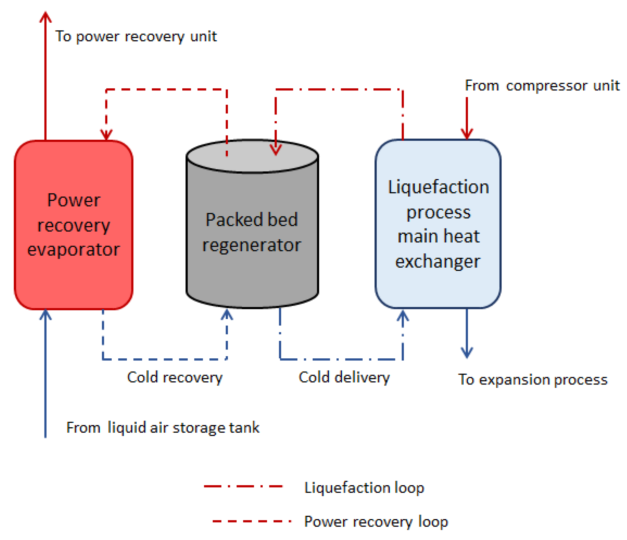
Energy storage devices are necessary to balance electrical grids that are increasingly powered by intermittent renewable resources [1,2]. Electricity generated during times of low demand or by intermittent sources can be stored and later used during periods of high demand [1]. Pumped hydro storage is considered one of the most attractive and robust solutions, but deployment is limited by the need for specific geological conditions [3]. Other technologies, such as batteries and compressed air energy storage, have been proposed and deployed on a limited scale. Cost, geographic constraints and environmental impacts have limited wider deployment. Compressed air storage has similar geographic constraints to pumped hydro, and is reliant on suitable geological features, such as salt caverns, to store the compressed air. Batteries provide an attractive solution for local grid reinforcement and frequency balancing, but are expensive for large scale energy and power management [4]. Liquid air energy storage (LAES) has received increasing attention as a potential large-scale storage concept to overcome the major geographical requirement characteristic of pumped hydro and compressed air energy storage, as well as the high cost of batteries [3,5]. Surplus electrical energy is exploited to liquify air that is used as a means of storing thermal energy in a tank. Electrical energy is later re-generated on demand by compressing the liquid air and using thermal energy available in the environment to heat the liquid and expand the warm, high-pressure air through a turbine [5,6]. To improve the process’ overall efficiency, Highview Power proposed a LAES layout with the addition of a packed bed regenerator (PBR) that is used to capture and store cold thermal energy that would otherwise be wasted during discharge (see Figure 1).
In this approach, the PBR is contained within a closed loop, with low-pressure air acting as the working fluid (see Figure 2). Thermal energy is recovered and transferred to the main LAES process indirectly via a heat exchanger, meaning that the PBR is not exposed to the high working pressures during power recovery and liquefaction. During power generation, the stored liquid air is passed through an evaporator, with the PBR loop acting as the heat source. The cold energy extracted from the liquid air stream is transferred to the PBR material via forced convection; this is referred to as charging the PBR. During liquefaction (i.e., charging of the LAES plant), the stored cold energy is used to provide additional cooling in the main heat exchanger and the PBR is returned to its state at the start of the power generation phase. This is referred to as discharging the PBR. It should be noted that the LAES process is discontinuous. Once the charging phase is complete and the liquid air tank is full, the process is stopped until energy is required, at which point, the discharge part of the cycle starts.

1.2. Choice of High-Grade Storage Concept

Due to the wide range of operating temperatures of the working fluid (−196 °C to 10 °C), technologies that use cryogenics liquids are impractical for an LAES application. Most cryogenics fluids, when stressed over a 200 °C temperature range, will undergo a phase change, reducing the overall system efficiency and complicating the design of the thermal store. A hybrid approach using propane and methanol was proposed by Ding [7]. This solution required two thermal stores, which increased the overall system complexity. Instead, a PBR that uses rock and gravels, or other cheap and widely available materials, can be relatively easily integrated in an LAES system and cover the complete temperature range in a single device. Different material options were discussed by Morgan [5] which included thermal, energy density and cost metrics. Gravels, especially quartz-based materials, offer a good mix of appropriate thermal properties at low cost and are robust to thermal cycling between room temperature and cryogenic temperatures. However, there is a paucity of data for material properties at cryogenic temperatures and the performance of a PBR in this region. A further complication is the variability in shape of a natural material such as gravel. Without expensive pre-processing, differences in size and shape are inevitable. Some limited work was done on the effect of variability of the fill material of a PBR but not on the specific material and conditions considered here. Pike-Wilson [8] published a study of the thermal properties, where different samples of sandstone and granite were tested under representative temperature ranges. The heat capacity (and hence thermal storage capacity) was observed to vary by a factor of three over the expected temperature range, showing the importance of accurate thermal properties at the low temperature range encountered in this application [9].

1.3. Modelling of Packed Bed Regenerators

The key attributes of the PBR are the thermal storage capacity, pressure drop and self-discharge through losses to the environment and through the dissipation of thermal energy along a partially charged store. To limit design uncertainties, numerical models have been developed to investigate PBR heat transfer mechanisms and performance. Early models were based on a single charge phase defined as the period during which a gas, characterised by a temperature below 150 K, passes through a PBR [10]. A limitation of this approach is that system losses due to cyclical operation were not considered. The overall geometry of the PBR and size of the solid phase particles must also be considered. The aspect ratio of the PBR effects the gas phase flow field, with a large aspect ratio resulting in increased velocity through the store and potentially a higher gas-to-solid phase heat transfer coefficient at the expense of higher pressure losses. Considering the solid phase particles, intuitively smaller particles give an overall increase in surface area for a given mass of material, improving heat transfer. However, Cascetta [11] showed that improved PBR efficiency can be achieved by increasing the particle diameter and aspect ratio. It was proposed that a particle diameter of 10 mm for an aspect ratio of 2 is the optimal value for best performance. Xu et al. [12] showed that particle diameter significantly affects PBR thermal performance, with increased particle diameter reducing the heat transfer rate and decreasing the effective charging time. Increased temperature difference between the solid particles and the fluid negatively affects the charging efficiency of larger particles. This is due to the temperature gradient within the particle becoming significant with larger particles (typically over 20 mm diameter). Therefore, there are differences in reported findings on the effects of geometric factors on the performance of a PBR.
Ideally, particles should be uniform in size and shape, so the particles pack evenly with the particle size being optimised to achieve the best heat transfer performance [12,13]. Van Antwerpen et al. [13] noted that available models for packed beds did not accurately define the packing structures and therefore did not accurately predict thermal conduction between the particles. This work focused on packed beds characterised by mono-sized particles and investigated the effect of porosity and heat transfer through conduction, for both the solid and gas phases, and the impact of particle contact area. Models were seen to give reasonable accuracy for the bulk region, but not for the near wall region.
The research reported here used natural gravels with minimal treatment—simply washing and drying and no milling to smooth and “round” the particles. The volume of material required for an LAES device means sourcing local material with minimal treatment would be highly preferable. As reported above, a larger surface area (relative to uniform round particles), due to the inhomogeneity of the gravel, can aid heat transfer between gas and solid phases. However, uncertainty and variability in the resulting void fraction of a packed bed with non-uniform particles can result in variations in the flow field, higher pressure losses and variations in the temperature field. The shape of the particles influences the bed packing density, and hence the material mass available for storage, and consequently the pressure drop. Achenbach [14] showed that the void fraction is higher in the near-wall region of a PBR due to the stacking of particles, leading to a non-uniform flow resistance across the bed and hence changes in the velocity profile and radial temperature distribution. Klein et al. [15] investigated the radial temperature distribution in a high-temperature packed bed, showing that solid particles at the tank wall increased in temperature slower than those in the centre. It was hypothesised this was due to increased heat losses to the wall via radiation and convection. The same effect was noticed when the packed bed was cooled, with the region near the wall showing lower temperatures than the centre.
Numerical simulations allow key design parameters to be optimised before committing to the construction of a potentially large and expensive thermal store. A one-dimensional (1-D) model, using rocks as the solid medium and air as the fluid was used to assess the effect of different design parameters on the performance of a packed bed [16]. Results showed that improved thermal efficiency could be achieved by decreasing the tank height to diameter ratio and rock diameter at the expense of higher pumping work and pressure drop. However, no general guidelines for packed bed design were proposed. It was suggested that each unit should be designed to optimise the performance and costs based on the application.
Chai et al. [17] investigated the effect of system pressure on the PBR temperature profile for a bed with 9 mm pebbles using liquid nitrogen as a heat transfer fluid. Two separate meshes were used to sift the filler material; this was done to improve the consistency of the particle diameter, and as a means of estimating the void fraction of the bed. The two pressures investigated were 0.1 MPa, representative of atmospheric pressure, and 6.5 MPa, representing supercritical conditions. Results showed pressure dependent temperature profiles, characterised by a thermocline for both charging and discharging. Moreover, the temperature difference between the centre of the PBR and the wall was influenced by the system pressure. The paper also presents temperature dependent data on heat capacity, but these are not then used to compare any simulation results with the experimental results from a packed bed test rig.
Oro [18] assessed two models for packed beds from experimental data, a continuous phase model and a second model that considered the temperature gradient of each individual solid particle. Both models showed that free convection dominated the forced convection heat transfer mechanism. This will vary with the flow rate, with lower or no flow conditions being dominated by free convection. In a LAES system, forced convection will be the dominant mechanism during charging and discharging. Even though the temperature profile of the solid particles was predicted with good agreement, the fluid flow in a packed bed cannot be defined in diffusion-based models.
The majority of published models are adapted from the two-phase Schumann model, presented in Willmott [19] and later by White [20]. This approach developed to predict the axial temperature distribution along a PBR with air as the heat transfer fluid. The Schumann model assumes no radial heat conduction in the fluid and no heat exchange between the particles. Vortmeyer [21] presented a simplified, single phase version of the Schumann model, and included axial thermal conduction. The model was also adapted for the case where the thermal conductivity of the solid material is significantly larger than that of the working fluid. Mawire et al. [22] used the Schumann model approach to investigate the use of fused silica, aluminium and stainless steel as filler material, evaluating these materials via axial temperature behaviour, energy and exergy stored, and transient charging efficiency. Results highlighted that the total energy stored, defined as the total exergy stored and degree of thermal stratification, is a key characteristic for the thermal performance of a PBR. Mawire et al. [22] reported an improvement in accuracy, compared to the Schumann model, in the prediction of the experimental temperature distribution; the biggest discrepancy between predicted and experimental data occurred at the centre of the PBR [22]. The centre of the PBR corresponds to the greatest thermal mixing location which is not represented in the 1-D model and thus results in the observed discrepancies. Approaches based on the Schumann model or simplified single-phase models define a constant heat transfer coefficient in the axial direction of the PBR based on inlet material properties limiting their ability to predict transient flow effects associated with mixing and their influence on heat transfer. Hänchen [23] investigated the thermal performance of PBR with four different materials: aluminium, rock, steatite and steel. Similar temperature results were reported for aluminium and rock, despite significant differences in their thermal conductivities, 204 and 0.48 W/mK, respectively. Instead, the similarity of volumetric heat capacity, 2419 and 2458 kJ/m3K for aluminium and rock, respectively, was identified as the key parameter. The particle to fluid convective heat transfer was determined to strongly influence the shape of the temperature distribution, while the smallest particle size gave rise to the highest efficiency.
White and McTigue [24,25] proposed a stricter thermodynamic interpretation that included the effect of varying pressure. However, for a low pressure PBR, the pressure effects are negligible and so do not merit the additional complexity of including these terms.
There is disagreement within the literature regarding the key PBR parameters required for obtaining accurate predictions of the bed temperature distribution. Models are often adapted to meet specific experimental conditions where material properties are available within the literature [25], with the Schumann model [20] for high temperature packed beds used as a basis. Others have included radiation effects, that can clearly be discounted in a cryogenic PBR. Almost all modelling approaches assume fixed thermal properties of the storage material. This assumption may be appropriate for high temperature stores but can lead to significant errors in a cryogenic PBR, where critical properties such as heat capacity can vary by a factor by over 50% across the operating temperature range. For example, the impact of assuming a constant room temperature value of the specific heat capacity would result in a 50% error in the calculated thermal storage capacity of a PBR operating between 300 and 100 K.
In this paper, we first introduce the fundamental theory of the heat transfer processes in the packed bed regenerator. The theoretical response to key thermal and physical properties, with experimental validation, is then presented. Later, a new modelling approach combining existing frameworks is presented and validated by results from a lab scale regenerator. The performance of the model is then discussed and the implications of the findings on the design of a packed bed regenerator at the scale required for a LAES plant are presented. The novelty of the research is in two areas: first the application of existing modeling frameworks to a cryogenic PBR; and second the implementation of temperature dependent thermal and fluid properties for both the gas and solid phases of the PBR. As we demonstrate in our work, significant errors will result from using constant and extrapolated values of key properties.

2. Theoretical Model of a Packed Bed Regenerator

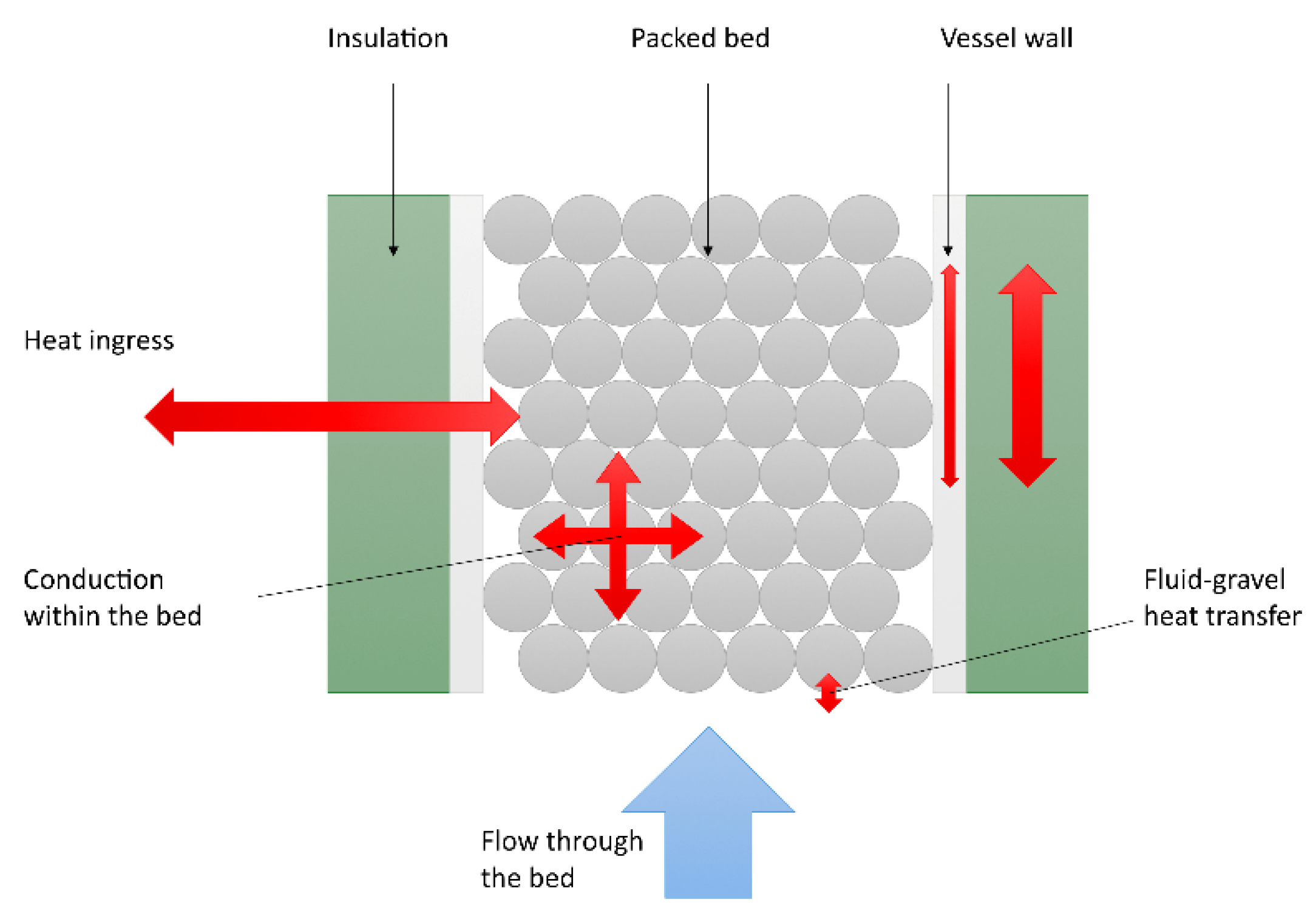
Figure 3 shows a cross-section through the PBR and the main heat transfer paths. Thermal energy is transferred between the solid and gas phases via convection. Heat can also be transferred by conduction between particles along the length and normal to the flow direction. Axial heat transfer can be significant if the thermal conductivity is high, such as with a metal filler material but is less so with poor conducting materials, such as quartz-based gravels. Radial heat transfer can also be significant if wall heat losses are high, but in the case of a well-insulated store, the radial heat flux is almost negligible.
Another conduction path is along the vessel walls that again, can be significant if the wall material is a good conductor, but can be neglected in many cases, especially for large stores where the vessel wall thermal mass is insignificant compared to the packed bed mass. In the present research, several assumptions were made:
  • Particles can be treated as round and uniform with a characteristic diameter for the purpose of calculating the solid-to-gas phase heat transfer coefficient.
  • There is no temperature gradient across the particle, i.e., the Biot number is near zero.
  • Flow only travels in the axial direction with no recirculation and with a uniform velocity across the diameter of the PBR (plug flow).
  • Heat transferred by conduction through the solid phase in the axis of the PBR is negligible.
  • Heat is lost to the environment through the walls of the PBR, but the resulting temperature gradient at right angles to the flow, is negligible (i.e., the store is well insulated).
  • The gas-to-particle heat transfer coefficient can be approximated using an empirical relationship between the Nusselt and Reynolds number, with temperature-dependent fluid properties. The length term is based on the particle diameter and the velocity term on the superficial velocity (velocity for an empty packed bed).
  • The heat capacity (Cp) of the particles varies only with temperature.
  • The thermal conductivity of the particles (k) can be approximated to a constant value with no variation with temperature.
  • The thermal conductivity through the packed bed can be approximated to the volume-averaged value of the solid and liquid phases.
  • Fluid properties vary with both temperature and pressure.
  • The void fraction is constant in axial and radial directions.Radiative heat transfer is negligible due to the low temperature.
The Schuman approximation can therefore be used with three governing partial differential equations:
T f t = u T f x + x ( k e ρ f ( T f ) C p , f ( T f ) T f x ) + h a ρ f ( T f ) C p , f ( T f ) ε ( T s T f ) + h w A w , i ρ w C p , w ( T w ) ( T w T f )
T s t = h a ρ s C p , s ( T s ) ( 1 ε ) ( T f T s )
T w t = x ( k w ( T w ) ρ w C p , w ( T w ) T w x ) + h w A w , i ρ w C p , w ( T w ) ( T f T w ) + h A w , o ρ w C p , w ( T w ) ( T T w )
In addition, the pressure drop through the store can be modelled using Ergun’s equation [26]:
P x = 150 μ ( 1 ε ) 2 D s 2 ε 3 u 0 + 1.75 ρ ( 1 ε ) D s ε 3 u 0 2
The model used in this study differs from the traditional Schumann model due to the inclusion of property changes with temperature, which are negated in both the Schumann and White models. Constant material properties can be assumed for a narrow temperature range. However, this is not suitable with the packed bed ranging from ambient, 273 K, to cryogenic temperatures, 77 K.

3. Determination of Physical Properties

The thermophysical properties of rocks are relatively well-characterised at high temperatures [11,23,27], but there are no readily available data for material properties at cryogenic temperatures. The properties of the materials that affect the packed bed storage capacity are the specific heat capacity and the thermal conductivity. These characteristics are temperature dependent and are needed to size the packed bed. A range of rock samples, including granite and sandstone, were studied to understand the relationship between temperature and the specific heat capacity. Sandstone is made up mainly of quartzite, whereas granites are a mixture of quartz, feldspars and mica. The motivation of this study was to understand if a characteristic relationship between temperature and heat capacity exists, or if the relationship is strictly dependent on the exact morphology of the rock.
Measurements of the specific heat of gravel, granite and sandstone at 185 K for use in large-scale cold storage using liquid nitrogen were previously performed by Pike-Wilson [8]. In summary, the specific heat measurements for temperatures below ambient were conducted using a method adapted from Consolmagno [28] that uses known changes in the mass and temperature of the samples and known fluid enthalpy to calculate the specific heat (see Equation (5)). A dewar, filled with a liquid nitrogen, was positioned onto measuring scales with an accuracy of ± 0.01 g. The mass was recorded, with an initial time given for the fluid to stabilise and the mass reading to be constant. Measurements at 248 K were conducted using a mixture of dry ice (solid CO2 at 194 K) and methanol at a ratio of 64:36 w/w. This mixture, commonly used in ice baths, is a slurry which holds a temperature of 201 K. The enthalpy of the mixture is measured using a copper sample of a known specific heat capacity. Copper with known specific heat values was used to validate the experimental methodology for each temperature using:
Q = ( m   c p   Δ T ) s a m p l e = ( m e v a p   h ) f l u i d
The specific heat capacity of granite and sandstone samples in the temperature region of 140 K to 320 K was also measured by Pike-Wilson [8]. The large size of the granite and sandstone sample, approximately 5 cm3, allowed a thermocouple to be positioned in the centre and on the side of the sample, ensuring a constant temperature through the sample. Specific heat capacity measurements at ambient temperatures were taken based on the previously described drop method. The granite and sandstone samples were first heated in an oven to dry the sample and achieve a uniform hot temperature. The samples were then dropped into cold water, and the temperature profiles of both the water and the samples were recorded. The known specific heat capacity of water and the temperature profiles can be used to calculate the specific heat of the rock samples.
Four gravel samples were selected to represent a range of quartzite-based rock compositions found in the UK. The gravel samples were inserted into the liquid nitrogen using a stainless-steel sampling ladle. The mass change in the liquid nitrogen due to the sampling ladle was also recorded. Experimental measurements of the gravel specific heat capacity at 185 K are shown in Table 1. No statistically significant difference between the four samples was observed, with the coefficient of variance of the data being under 3%. Based on this limited data set, it is proposed it is safe to use a generic material rather than sample specific value of Cp i.e., once a general rock type is characterized, this value can be used for material from different geological locations.
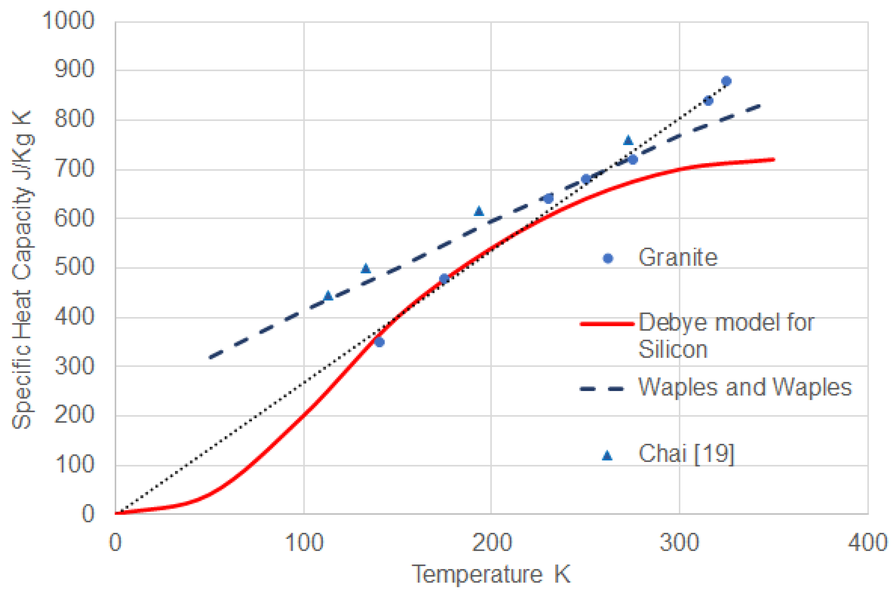
The temperature-dependent properties of a granite and sandstone sample are presented in Figure 4. Published data from Waples [29] and predictions by the Debye model [30] are included on the plot. Fundamentally, at absolute zero the heat capacity of a solid is considered to be zero.
Therefore, it is appropriate to extrapolate the experimental data to cross the origin of the plot. It is clear from the data gathered in the present research that the extrapolation of experimental data and theoretical models, derived from high-temperature properties, would lead to significant errors at low temperatures. Therefore, direct measurements of heat capacity for generic material types at cryogenic temperatures are required to ensure accurate representation of this key property in a simulation of a PBR (as described in Section 2). However, little variation was observed between different samples of the same generic material, so generic material properties can be used if measured at representative temperatures.

4. Experimental Study of a Lab-Scale PBR

4.1. Description of the Test Rig

A lab-scale PBR was built using a Polytetrafluoroethylene PTFE tube with a 100 mm internal diameter and a 1440 mm long test section full of gravel. Headers of generous volume and a diffuser were included at each end of the regenerator to ensure even distribution of the flow field and minimise end effects. PTFE was selected as it is (a) compatible with cryogenic temperatures and (b) has a low thermal conductivity (unlike stainless steel or aluminium). The store was insulated using one layer of a high-grade cryogenic insulation of 25 mm thickness. During testing, some condensation was observed on the outside of the insulation but no freezing, indicating the effectiveness of the insulation.
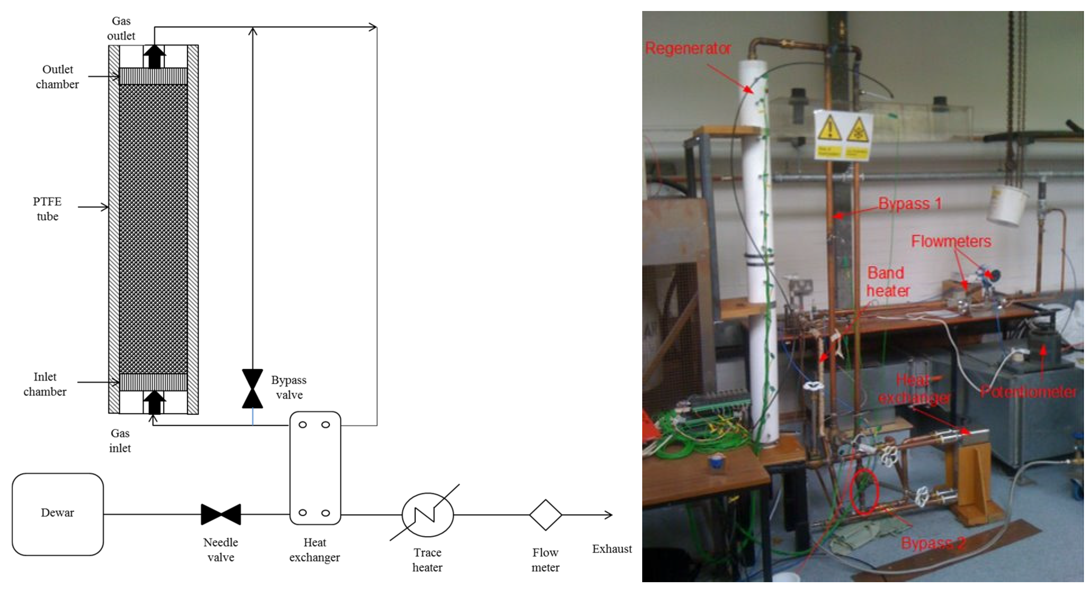
Liquid nitrogen (LN2) from a cryogenic dewar was used as the working fluid to provide a supply of cold dry nitrogen gas. Figure 5 shows an overall schematic and photograph of the experimental rig. Gravel temperatures inside the PBR were recorded using thermocouples located along the test section at equally spaced distances. The thermocouples were installed so the tip was positioned in the middle of the section and so would be only partially in contact with the gravel. The local temperature is therefore an average of the gas and solid phase. However, as it was assumed the temperature gradient inside a gravel particle is negligible, the error in assuming that the thermocouple records a representative solid phase temperature is considered small. Inlet and outlet gas temperatures were recorded using two thermocouples located in the inlet and outlet chamber. These two chambers acted as manifolds, providing an even gas distribution. Additional thermocouples were positioned on the internal and external wall to calculate the heat loss. All thermocouples had a manufacturer uncertainty of 1%. A heat exchanger was used to evaporate the liquid nitrogen using the exhaust of the PBR to provide heat. A bypass valve downstream the heat exchanger was used to control the inlet gas temperature by regulating the flow into the heat exchanger. A Druck PDCR 810 pressure transducer, with a range of 3.5 bar gauge and a manufacturer uncertainty of 1.5%, was used to record inlet and outlet PBR pressures. A SMC-PF2A703H-10-28 flow meter located downstream of the exhaust pipe was used to measure the gas flow rate. A trace heater was added to ensure that only warm gas passed through the flow meter, so the gas was within the operating range of the flowmeter. The chosen flow meter measures the volumetric flow rate as L/min with an uncertainty of 1%. The volumetric flow was converted to mass flow by using the pressure and temperature readings just upstream of the flowmeter. The thermocouples, pressure sensors and flow meter measurements were recorded using an instruNET datalogger at a rate of 1 Hz.
Two different gravel types, 10 mm and 20 mm quartzite, were used to investigate the effect of particle size and flow rate on the PBR performance. The gravel particle size is defined by the sieve through which the gravel will pass rather than a mean characteristic diameter. However, only one orientation of the gravel is required to pass through the sieve, so variation in the actual gravel size, which will affect the PBR packing density, is inevitable but also representative of what would be expected in a large-scale thermal store.

4.2. Determination of Void Fraction

The void fraction (solid phase volume/total volume) is an important modelling parameter and was calculated by recording the mass of gravel added to the test section of the store. Results for a number of fills are shown in Table 2. Chai [17] calculated that the void fraction between particles characterised by an average diameter of 9 mm is 0.4 If all particles had a perfectly spherical shape and were perfectly packed, the minimum void fraction would be lower, at 0.26 [14]. The void fractions reported in Table 2 are based on the initial filling of the packed bed, before the PBR has been charged. The gravel in the PBR is subject to stress as the tank walls expand and contract with temperature. Moreover, the gravel is exposed to very low temperatures and, as a result, may crack with thermal stress. These two factors can result in the gravel shifting during testing, which will change the bulk void fraction. The void fraction can also vary along the PBR as smaller particles settle near the bottom. These factors are not considered in the current study and the void fraction is assumed to remain constant along the PBR.
The gravel is clearly not a set of uniform spheres and shows variation in aspect ratio and size. An attempt was made to characterise the samples by measurement of the long and short axis of a sample of particles, but no robust correlation was found. It was instead decided to use the nominal sieve size as the characteristic dimension, as this is how the raw material is sorted and provides the most useful characteristic dimension when sourcing material for a large PBR.

5. Experimental Results

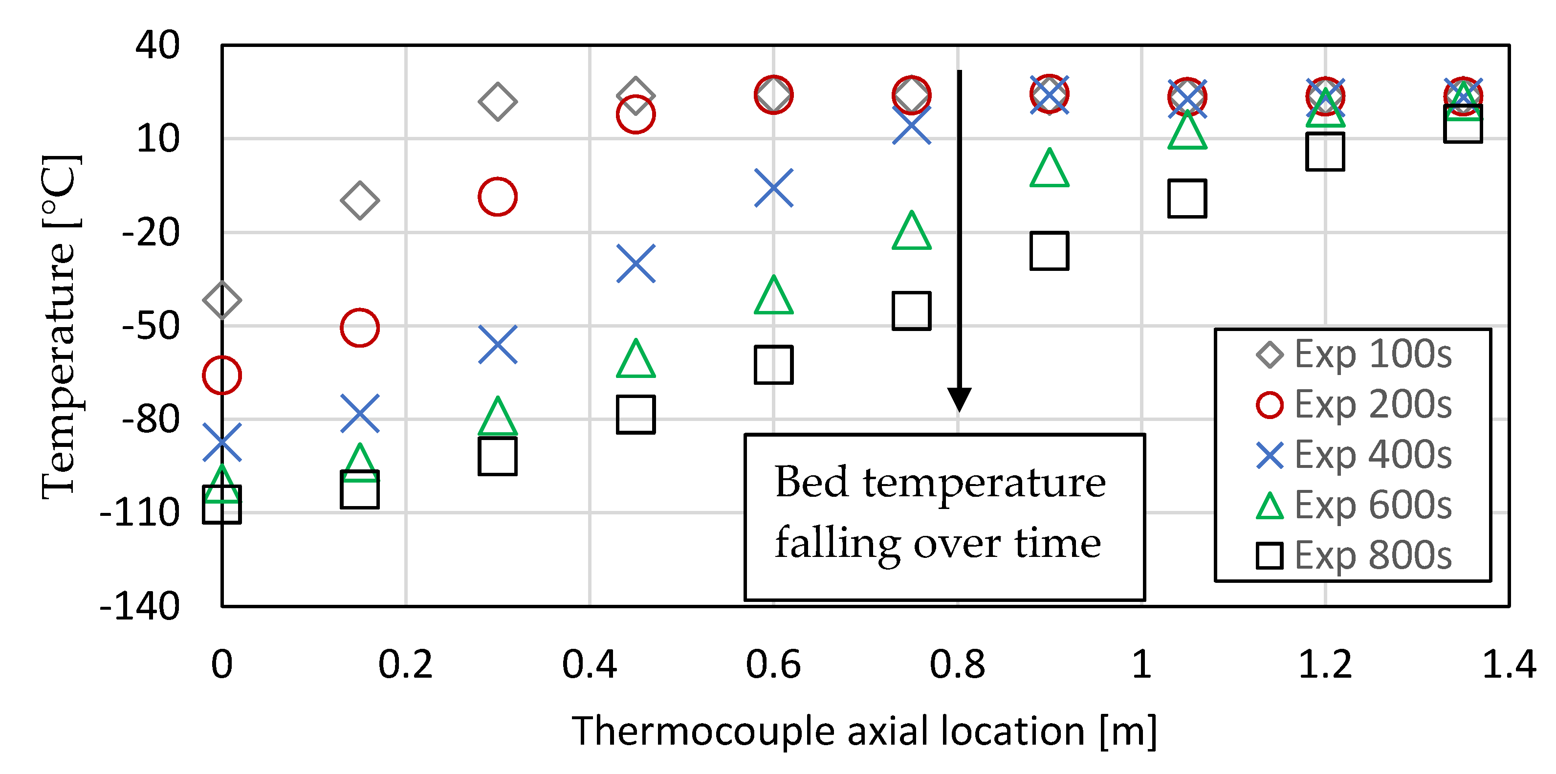
A series of different flow rates were tested for 10 mm and 20 mm gravels. A typical plot of temperature at the thermocouple locations for different time intervals is shown in Figure 6 for a Reynolds number of 2074. As can be seen, the temperature front propagates through the store over time, producing a series of sigmoidal fonts until the temperature at the outlet of the PBR starts to fall, indicating that the store is nearly full.
Figure 7 shows results for 10 mm gravel and 8 for 20 mm gravel at different Reynolds numbers. Results from the simulation study are included on the plots and will be discussed in the next section. The Reynolds number achieved for the smaller 10 mm gravel is lower than the 20 mm sized gravel, as a higher flow rate could be achieved due to the lower pressure drop encountered for the larger gravel.
It should be noted the initial temperatures are lower at high Reynolds numbers as the first results taken were 100 s after the start of the test; thus, the start of the bed will be cooled more in the initial phase at higher flow rates. Data are not reported at time zero due to variations in stabilization of the flow at the start of the experiment.

6. Modelling

The model was implemented in the Aspen suite. This platform was chosen so the thermal storage model could be integrated, if necessary, into a full system model of the LAES system. The computational time step was adjusted automatically within the software to minimise error. A computational grid size of 150 mm was selected. Fluid properties were derived from the Peng–Robinson equation of state that comes with the Aspen software and is known to be accurate at cryogenic conditions [32]. A temperature-dependent heat capacity model based on a linear fit through the earlier reported experimental data was implemented. A value of 8 W/mK was assumed for the thermal conductivity of the gravel based on typical values from the literature. Ideally, this would have been measured at cryogenic conditions, but suitable equipment was not available, and conduction is a secondary factor relative to the convective heat transfer and thermal inertia of the PBR. The thermal conductivity through the packed bed (ke) can be approximated to the volume averaged value of the solid and fluid phases. The void fraction was determined experimentally as described above. The particle size was iterated to give the lowest error across the data set at different flow rates, reflecting the fact that the sieve size does not truly represent the particle size.
Finally, an empirical correlation was used to determine the convective heat transfer coefficient, proposed first by Gnielinski and later by Srinivasa [33] for the laminar (Nul) and turbulent (Nut) and effective Nusselt number for the PBR (Nu). The correlations are valid for air for a Prandtl range of 0.7 to 104 and Reynolds numbers up to 7.7 × 10⁵, within the range of the experimental results:
N u l = 0.664 R e 0.5 P r 0.33
N u t = 0.037 R e 0.8 P r ( 1 + 2.443 R e 0.1 ( P r 0.66 1 )
N u = 2 + ( N u l 2 + N u t 2 ) 0.5
where Re the Reynolds number and Pr the Prandtl number. The length term in the Nu and Pr numbers is referenced to the nominal diameter of the packed bed particles. The velocity term is the superficial (equivalent empty PBR) gas velocity. Temperature-dependent fluid properties (using the Peng–Robinson equation of state implemented in the Aspen software) were calculated at each time step and position using the local fluid properties.
A correction factor was applied to the mass flow and matched to the experimental data (the matched model results are shown on Figure 7 and Figure 8). It is hypothesised that this factor accounts for flow short circuiting the main section due to lower packing density at the edge of the store. The value of the correction factor was iterated together with the particle diameter to achieve the best overall match at different flow rates for the same pack bed fill. The rational for this was that the packed bed fill does not change from test to test, so there is no justification for changing the chosen particle diameter for a given fill. However, the amount of flow short circuiting will change from test to test with flow rate, so there is justification in changing this factor.
Figure 9 shows the variation in correlation factor applied for all the experimental cases considered against the least squared fit for different assumed values of void fraction. The values with key parameters are also tabulated in Table 3. Some dependence with the assumed void fraction is observed, which is unsurprising as the void fraction strongly affects the flow resistance and how much flow is short circuited. However, a value of 0.56 gives the best fit independent (within the accuracy of the experiment) of the void fraction. Table 3 also records the effective particle diameter that gave the best model fit. For the 20 mm sieve material, 20 mm gave a good result, whereas a larger 14 mm particle size was used for the 10 mm sieve material. As previously mentioned, the sieve size will let smaller particles through and traps some large ovoid particles, but it may let some through dependent on the orientation of the particle. Therefore, the sieve size only gives an approximation of the effective particle size for the purpose of modelling the packed bed. It is, however, encouraging that the sieve size is close to the optimal diameter for matching the model and therefore a good first approximation of the effective particle size. At the best overall fit, the error is also independent of the assumed void fraction and in the range of the bulk-measured value of void fraction.

7. Discussion

The importance of temperature-dependent thermal property data was demonstrated through the measurements made on heat capacity. If the room temperature value of Cp is used, the storage capacity of the PBR would be overestimated by 50% over a 300–100 K operating range. Using the temperature-dependent values from the Debye model or Waples extrapolation reduces this error to 7%. It is, however, apparent from a limited set of results, but on a broad range of rock types, that a generic heat capacity can be used to characterise quartz-based rocks without the need to characterise each specific sample.
From the experimental data with temperature-dependent fluid and solid phase specific heat capacity properties, a good match was achieved between the experimental and modelling results by using a correction factor to the flow. It is proposed that some of the flow short circuits the store and reduces the effective flow rate, which, from inspection of the fill of the store, is a reasonable explanation. Other researchers have made similar observations. Obitz [34] and Martin [35] observed the porosity increases in the near-wall region of a packed bed, resulting in a reduction in flow resistance. Geissbuhler et al. [36] attempted to account for this by introducing a bypass flow fraction of 7.5%. Similarly, Hanchen et al. [23] introduced a bypass flow fraction of 15% to their numerical model to achieve good agreement between experimental results and numerical predictions. It should be noted that the packing regime in the near wall region will be dependent on the fill material and size of the store, so differences in the effect of bypass flow are to be expected.
Using statistical analysis, some dependence of the correction factor with fill void fraction was observed. Void fraction affects the flow field, and so it would be expected that more flow would bypass the packed bed if the flow resistance were higher. However, using a void fraction-independent correction factor of 0.56 resulted in minimal error.
However, the correction factor is likely to be dependent on the size of the PBR, as the relative effect of flow around the edge of the store will be lower for larger stores. This is because the relative flow area in contact with the wall of the PBR reduces as the diameter of the store increases. It is possible for a full size LAES device to have a negligible flow correction. Thus, although the overall approach is useful, care must be taken scaling the model, as the correlation factor will have a geometric dependence on the size of store and possibly size of particle. Further work is required in this area, possibly using CFD to investigate the edge effects at the periphery of the store. It may be possible using a single CFD model to derive an appropriate correction factor for a larger store and use the proposed 1-D approach to model a range of flow conditions and small geometric changes, such as diameter and length. However, at this stage of the research, this approach requires validation.

8. Conclusions

An experimental and modelling programme that investigated the heat capacity and thermal profile of a lab-scale packed bed regenerator at cryogenic conditions was successfully completed.
Temperature-dependent heat capacities were measured for a range of quartz-based rocks that showed (a) strong dependence of heat capacity on temperature and (b) similar values of heat capacity for the range of materials studied. Based on the results, extrapolation of high-temperature data will result in significant inaccuracies (as high as 50%), but a generic relationship for quartz-based materials can be used. The implication of this is that the exact sample does not need to be characterised, and once a representative sample of materials is characterised, a general value can be applied.
A modified Schuman model, with temperature-dependent gas and fluid phase properties was implemented in the Aspen software environment. To match the experimental results, a correction factor of 0.56 was applied to the flow rate. It is hypothesised that part of the flow short circuits the main gravel section of the PBR and flows up the sides of the store where there is less flow resistance. Some dependence of the correction factor on void fraction was observed, but the use of a void fraction-independent value results in minimal error.
It was proposed that the flow correction factor would depend on the diameter of the store as the amount of flow short circuiting the main gravel section is likely to depend on the diameter and be less significant for larger stores. An investigation of this hypothesis is the subject of future research.

Author Contributions

R.M. was the principle investigator and lead the preparation of this paper. E.P.-W. and T.G. lead the experimental program, and T.G. conducted the modelling work. C.Q. worked with R.M. in developing the technical arguments and peer review of the results. C.R. conducted further analysis of the data and contributed substantially to the writing of the paper. All authors have read and agreed to the published version of the manuscript.

Funding

This research was funded by Innovate UK under the Knowledge Transfer Partnership scheme (grant number KTP0096256) and through the Highview Heat Storage project (grant number 133465).

Acknowledgments

The authors would like to thank Catherine Brown for her help in preparing this article and Mario Palermo for his help in building the test rig.

Conflicts of Interest

The authors declare no conflict of interest. The funders had no role in the design of the study; in the collection, analyses, or interpretation of data; in the writing of the manuscript, or in the decision to publish the results.

Nomenclature

Aw,iPacked bed inner wall area
Aw,oPacked bed outer wall area
aSpecific surface area of packed particles
DsDiameter of particle
kwPacked bed wall thermal conductivity
kePacked bed effective thermal conductivity
NulLaminar Nusselt number
NutTurbulent Nusselt number
hwPacked bed internal wall heat transfer coefficient
hHeat transfer coefficient between fluid and packed bed particles
PPressure
PrPrandtl number
ReReynolds number
TfTemperature of fluid
TsTemperature of solid particle
TwTemperature of packed bed wall
TAmbient temperature
tTime
uInterstitial packed bed fluid velocity
u0Superficial packed bed fluid velocity
hHeat transfer coefficient from outer wall to ambient
xAxial distance along the PBR
ρfFluid density
ρsPacked bed particle density
ρwPacked bed wall density
Cp,fFluid specific heat capacity
Cp,sSolid particle specific heat capacity
Cp,wPacked bed wall specific heat
µFluid viscosity
εVoid fraction

References

  1. Strbac, G.; Aundedi, M.; Pudjianto, D.; Djapic, P.; Teng, F.; Sturt, A.; Dejvises, J.; Sansom, R.; Yufit, V.; Brandon, N. Strategic assessment of the role and value of energy storage systems in the UK low carbon energy future. In Report for the Carbon Trust; Imperial College: London, UK, 2012; Available online: http://www.carbontrust.com/media/129310/energy-storage-systems-role-value-strategic-assessment.pdf (accessed on 20 February 2014).
  2. IEA (2019) World Energy Outlook; Paris. Available online: https://www.iea.org/reports/world-energy-outlook-2019 (accessed on 2 October 2020).
  3. Legrand, M.; Rodríguez-Antón, L.M.; Martinez-Arevalo, C.; Gutiérrez-Martín, F. Integration of liquid air energy storage into the Spanish power grid. Energy 2019, 187, 115965. [Google Scholar] [CrossRef]
  4. May, G.J.; Davidson, A.; Monahov, B. Lead batteries for utility energy storage: A review. J. Energy Storage 2018, 15, 145–157. [Google Scholar] [CrossRef]
  5. Morgan, R.; Nelmes, S.; Gibson, E.; Brett, G. An analysis of a large-scale liquid air energy storage system. Proc. Inst. Civil Eng. 2015, 168, 135–144. [Google Scholar] [CrossRef] [Green Version]
  6. Morgan, R.; Nelmes, S.; Gibson, E.; Brett, G. Liquid air energy storage—Analysis and first results from a pilot scale demonstration plant. Appl. Energy 2015, 137, 845–853. [Google Scholar] [CrossRef]
  7. Peng, X.; She, X.; Cong, L.; Zhang, T.; Li, C.; Li, Y.; Wang, L.; Tong, L.; Ding, Y. Thermodynamic study on the effect of cold and heat recovery on performance of liquid air energy storage. Appl. Energy 2018, 221, 86–99. [Google Scholar] [CrossRef]
  8. Pike Wilson, E.; Morgan, R.; Cundy, A. Cryogenic thermal energy storage systems. In Proceedings of the ASME-ATI-UIT 2015 Conference on Thermal Energy Systems: Production, Storage, Utilization and the Environment, Naples, FL, USA, 7–20 May 2015. [Google Scholar]
  9. Hüttermann, L.; Span, R. Influence of the heat capacity of the storage material on the efficiency of thermal regenerators in liquid air energy storage systems. Energy 2019, 174, 236–245. [Google Scholar] [CrossRef]
  10. Kuipers, J.A.M. Computational Fluid Dynamics Applied to Chemical Reaction Engineering; Springer: Berlin, Germany, 1999. [Google Scholar]
  11. Cascetta, M.; Cau, G.; Puddu, P.; Serra, F. Numerical Investigation of a Packed Bed Thermal Energy Storage System with Different Heat Transfer Fluids. Energy Procedia 2014, 45, 598–607. [Google Scholar] [CrossRef]
  12. Xu, C.; Li, X.; Wang, Z.; He, Y.; Bai, F. Effects of solid particle properties on the thermal performance of a packed-bed molten-salt thermocline thermal storage system. Appl. Therm. Eng. 2013, 57, 69–80. [Google Scholar] [CrossRef]
  13. van Antwerpen, W.; du Toit, C.G.; Rousseau, P.G. A review of correlations to model the packing structure and effective thermal conductivity in packed beds of mono-sized spherical particles. Nucl. Eng. Des. 2010, 240, 1803–1818. [Google Scholar] [CrossRef]
  14. Achenbach, E. Heat and flow characteristics of packed beds. Exp. Therm. Fluid Sci. 1995, 10, 17–27. [Google Scholar] [CrossRef]
  15. Klein, P.; Roos, T.H.; Sheer, T.J. Experimental Investigation into a Packed Bed Thermal Storage Solution for Solar Gas Turbine Systems. Energy Procedia 2014, 49, 840–849. [Google Scholar] [CrossRef] [Green Version]
  16. Zanganeh, G.; Pedretti, A.; Haselbacher, A.; Steinfeld, A. Design of packed bed thermal energy storage systems for high-temperature industrial process heat. Appl. Energy 2015, 137, 812–822. [Google Scholar] [CrossRef]
  17. Chai, L.; Liu, J.; Wang, L.; Yue, L.; Yang, L.; Sheng, Y.; Chen, H.; Tan, C. Cryogenic energy storage characteristics of a packed bed at different pressures. Appl. Therm. Eng. 2014, 63, 439–446. [Google Scholar] [CrossRef]
  18. Oró, E.; Chiu, J.N.; Martin, V.; Cabeza, L.F. Comparative study of different numerical models of packed bed thermal energy storage systems. Appl. Therm. Eng. 2013, 50, 384–392. [Google Scholar] [CrossRef]
  19. Wilmott, J. Dynamics of Regenerative Heat Transfer; CRC Press: Boca Raton, FL, USA, 2001. [Google Scholar]
  20. White, A.J. Loss analysis of thermal reservoirs for electrical energy storage schemes. Appl. Energy 2011, 88, 4150–4159. [Google Scholar] [CrossRef] [Green Version]
  21. Vortmeyer, D. Packed bed thermal dispersion models and consistent sets of coefficients. Chem. Eng. Process. Process Intensif. 1989, 26, 263–268. [Google Scholar] [CrossRef]
  22. Mawire, A.; McPherson, M.; Heetkamp, R.V.D.; Mlatho, S. Simulated performance of storage materials for pebble bed thermal energy storage (TES) systems. Appl. Energy 2009, 86, 1246–1252. [Google Scholar] [CrossRef]
  23. Hänchen, M.; Brückner, S.; Steinfeld, A. High-temperature thermal storage using a packed bed of rocks—Heat transfer analysis and experimental validation. Appl. Therm. Eng. 2011, 31, 1798–1806. [Google Scholar] [CrossRef]
  24. McTigue, J.D.; Markides, C.N.; White, A.J. Performance response of packed-bed thermal storage to cycle duration perturbations. J. Energy Storage 2018, 19, 379–392. [Google Scholar] [CrossRef]
  25. White, A.; McTigue, J.; Markides, C. Wave propagation and thermodynamic losses in packed-bed thermal reservoirs for energy storage. Appl. Energy 2014, 130, 648–657. [Google Scholar] [CrossRef] [Green Version]
  26. Ergun, S.; Orning, A.A. Fluid flow through randomly packed columns and fluidized beds. Ind. Eng. Chem. 1949, 41, 1179–1184. [Google Scholar] [CrossRef]
  27. Allen, K.G.; Von Backström, T.W.; Kröger, D.G. Packed Rock Bed Thermal Storage in Power Plants: Design Considerations. Energy Procedia 2014, 49, 666–675. [Google Scholar] [CrossRef] [Green Version]
  28. Consolmagno, G.J.; Schaefer, M.W.; Schaefer, B.E.; Britt, D.T.; Macke, R.J.; Nolan, M.C.; Howell, E.S. The measurement of meteorite heat capacity at low temperatures using liquid nitrogen vaporization. Planet. Space Sci. 2013, 87, 146–156. [Google Scholar] [CrossRef]
  29. Waples, D.W.; Waples, J.S. A Review and Evaluation of Specific Heat Capacities of Rocks, Minerals, and Subsurface Fluids. Part 1: Minerals and Nonporous Rocks. Nat. Resour. Res. 2004, 13, 97–122. [Google Scholar] [CrossRef]
  30. Debye, P. Zur Theorie der spezifischen Wärmen. Ann. Phys. 1912, 344, 789–839. [Google Scholar] [CrossRef] [Green Version]
  31. Pike-Wilson, E.; Gardhouse, T.; Morgan, R.; Heikal, M. Measurement and simulation of low temperature packed bed regenerators. In Proceedings of the 4th UK Heat Transfer Conference, Edinburgh, UK, 7–8 September 2015. [Google Scholar]
  32. Gopal, J.M.; Tretola, G.; Morgan, R.; de Sercey, G.; Atkins, A.; Vogiatzaki, K. Understanding Sub and Supercritical Cryogenic Fluid Dynamics in Conditions Relevant to Novel Ultra Low Emission Engines. Energies 2020, 13, 3038. [Google Scholar] [CrossRef]
  33. Rao, G.S.; Sharma, K.; Chary, S.; Bakar, R.; Rahman, M.; Kadirgama, K.; Noor, M. Experimental study on heat transfer coefficient and friction factor of a Al203 nanofluid in a packed bed column. J. Mech. Eng. Sci. 2011, 1, 1–15. [Google Scholar] [CrossRef] [Green Version]
  34. Opitz, F.; Treffinger, P. Packed bed thermal energy storage model. Generalized approach and experimental validation. Appl. Therm. Eng. 2014, 73. [Google Scholar] [CrossRef]
  35. Martin, H. Low Peclet number particle-to-fluid heat and mass transfer in packed beds. Chem. Eng. Sci. 1978, 33. [Google Scholar] [CrossRef]
  36. Geissbühler, L.; Kolman, M.; Zanganeh, G.; Haselbacher, A.; Steinfeld, A. Analysis of industrial-scale high-temperature combined sensible/latent thermal energy storage. Appl. Therm. Eng. 2016, 101. [Google Scholar] [CrossRef]
Figure 1. Simplified schematic of a liquid air energy storage device. Mass flows are shown with solid lines and thermal energy flows as dashed lines.
Energies 13 05155 g001
Figure 2. Simplified schematic of flow paths to the PBR during power recovery and liquefaction.
Energies 13 05155 g002
Figure 3. Cross-section through a packed bed regenerator showing conduction and flow paths.
Energies 13 05155 g003
Figure 4. Relationship between specific heat capacity and temperature from the present work and published correlations. Adapted from [8] and [17].
Energies 13 05155 g004
Figure 5. Schematic (left) of the lab-scale packed bed regenerator (PBR) as provided in [31] and photograph (right) without insulation.
Energies 13 05155 g005
Figure 6. Experimental temperature front at different locations and timesteps. Packed bed filled with 10 mm quartzite gravel, Re = 2074.
Energies 13 05155 g006
Figure 7. Experimental and predicted temperature front comparisons at different Reynolds numbers. Re = 2387, Re = 3315, Re = 3400 and Re = 4700. Packed bed filled with 10 mm quartzite gravel.
Energies 13 05155 g007
Figure 8. Experimental and predicted temperature front comparisons at different Reynolds numbers, Re = 5251 and Re = 8179. Packed bed filled with 20 mm quartzite gravel.
Energies 13 05155 g008
Figure 9. Effect of different void fraction and mass flow coefficients on the model results; 10 mm quartzite with constant particle diameter = 0.0014 mm.
Energies 13 05155 g009
Table 1. Experimental values of specific heat capacity of gravel at 185 K.
Gravel SampleCp (J/kg K)
Test 1Test 2
1518504
2498492
3479512
4515516
Table 2. Measured void fraction for the gravel samples.
GravelVoid Fraction
Quartzite 10 mm0.44
Quartzite 20 mm0.45
Flint 20 mm (for reference)0.49
Table 3. Summary of predicted void fraction, particle diameter and mass flow coefficients for all cases.
TestGravel Diameter [mm]Void FractionParticle Diameter (mm)Mass Flow CoefficientReynolds NumberPressure (barg)Flow Rate (g/s)
1200.325170.6347061.297
2200.350200.6561051.377.6
3200.325200.6352511.356.7
4200.350200.6379911.559.6
5200.350200.6581791.589.2
6200.350200.6583561.649.2
7100.470140.5833151.658.2
8100.400140.5823871.316
9100.460140.5634171.638.5
10100.450140.5634521.748.5
11100.443140.5647761.8910.6