Article

Effects of Nozzle Exit Position on Condenser Outlet Split Ejector-Based R600a Household Refrigeration Cycle

1
Department of Refrigeration and Air-Conditioning Engineering, Chonnam National University, 50 Daehak-ro, Yeosu, Chonnam 59626, Korea
2
Research Group of Consumer Safety, Korea Food Research Institute, 245 Nongsaengmyeong-ro, Iseo-Myeon, Wanju-Gun, Jeollabuk-do 55365, Korea
3
Department of Mechanical Design Engineering, Chonnam National University, 50 Daehak-ro, Yeosu, Chonnam 59626, Korea
*
Authors to whom correspondence should be addressed.
Energies 2020, 13(19), 5160; https://doi.org/10.3390/en13195160
Submission received: 1 September 2020 / Revised: 25 September 2020 / Accepted: 1 October 2020 / Published: 3 October 2020

Abstract

:
The objective of this study is to investigate the performance characteristics of a small-sized R600a household refrigeration system that adopts a condenser outlet split (COS) ejector cycle under various operating and ejector geometry conditions. The coefficient of performance and pressure lifting ratio of the COS ejector cycle were analyzed and measured by varying the entrainment ratio, compressor speed, and nozzle exit position. The optimum nozzle exit position in the COS ejector cycle adopted to achieve the maximum cycle performance was proposed as a function of the compressor speed and entrainment ratio. The optimum nozzle exit position was 0 mm when the entrainment ratio and compressor speed were low, and it increased as the entrainment ratio and compressor speed increased owing to the associated internal pressure drop in the suction section.

1. Introduction

Many household refrigeration cycles such as those used in refrigerators, air conditioners, dehumidifiers, and water purifiers are applied globally; consequently, several studies on improving the energy efficiency of household refrigeration cycles have been conducted [1,2,3,4,5,6,7,8,9,10]. The major irreversible losses in the household refrigeration cycle are generated by the throttling process, which requires the use of capillary tubes or an electrical expansion valve. Ejectors have attracted significant attention as a method for reducing these expansion losses. A two-phase ejector cycle is considered one of the most effective expansion methods for improving the energy efficiency of the refrigeration cycle through a reduction in the expansion loss [11]; it has been widely applied in high-pressure and high-capacity refrigeration cycles that suffer from significant expansion losses, such as the transcritical cycle [12,13,14,15]. He et al. [16] analyzed the exergetic efficiency in a transcritical CO2 cycle using computational fluid dynamics (CFD). Bodys et al. [17] proposed a bypass duct for a two-phase ejector in a transcritical CO2 cycle. In general, the absolute amount of pressure to be recovered is low, and it is difficult to use these two-phase ejectors with low-pressure refrigerants [18]. A majority of previous ejector-related studies have focused on a standard two-phase ejector cycle with a phase separator. However, practical problems such as oil circulation have been reported when a phase separator is used in a two-phase ejector cycle [19]. In particular, the application of a standard two-phase ejector cycle with a phase separator is unsuitable for household refrigeration cycles with a relatively low capacity and low operating pressure. In the household refrigeration cycle, the work recovery potential is low; thus, the ejector cycle needs to be modified because the operation of the secondary loop is unstable. Oshitani et al. [20] proposed a condenser outlet split (COS) ejector cycle as an air-conditioning control system in automobiles designed for low-pressure refrigerants. They found that the COS ejector cycle achieves good operation under off-design conditions and adaptability with low-pressure cycles. In addition, the COS ejector cycle has other advantages such as multiple evaporation temperatures, no need for phase separator and assisting in oil circulation.
Figure 1 shows the pressure–enthalpy diagrams of both the baseline and COS ejector cycles. The COS ejector cycle consists of a compressor, a condenser, an ejector, an expansion valve, and two evaporators with different evaporating pressures. Moreover, the baseline cycle is represented by the red line in Figure 1; this cycle comprises a compressor, a condenser, an expansion valve, and an evaporator. In the COS ejector cycle, as represented by the black line in Figure 1, the refrigerant flow from the condenser splits into two branches. One of the streams flows to the motive nozzle of the ejector, while the other flow flows to the expansion valve. The stream flowing toward the expansion valve is vaporized at the low-temperature evaporator and is entrained in the suction section of the ejector to meet the fluid passing through the motive nozzle. These two streams mix and slow down through the mixing section and diffuser of the ejector to recover the pressure. Thus, the operation principle of the COS ejector cycle can be defined as the motive flow from the condenser that entrains the secondary flow in the evaporator in the suction section and delivers a mixed flow at high pressure to the diffuser. As shown in Figure 1, the compressor suction pressure of the COS ejector cycle is higher than the pressure in the baseline cycle. This indicates that the mass flow rate and compression of the COS ejector cycle are higher and lower than those of the baseline cycle, respectively. Therefore, the compression and cooling capacity of the COS ejector cycle are lower and higher, respectively, than those of the baseline cycle. In addition, the compressor discharge temperature of the COS ejector cycle is lower than that of the baseline cycle owing to the increase in the compressor suction pressure of the COS ejector cycle. Lawrence and Elbel [21] compared the COP of the baseline cycle and the COS ejector cycle using R1234yf and R134a. More recently, Kim et al. [22] reported an experimental performance improvement of 6.3% in the seasonal performance of a residential air conditioner using a COS ejector cycle compared with the baseline cycle.
In recent years, the approach of optimizing ejector geometries to maximize performance efficiency has garnered significant research interest. Furthermore, the design of the nozzle has been reported to be a significant factor affecting the COP and the performance of the COS ejector cycle. Wang et al. [23] presented an optimum nozzle exit position (NXP) based on a numerical investigation using CFD. In addition, Wu et al. [24] and Palacz et al. [25] numerically analyzed the performance of the ejector cycle according to the ejector geometry conditions, particularly the mixing section and the nozzle of the ejector. Moreover, Yan et al. [26] demonstrated the influence of the ejector geometry on ejector performance using the CFD method. When the NXP is low, the pressure lifting ratio (PLR) becomes high because the kinetic energy of the motive flow is well transmitted. However, if the NXP is significantly short, the internal pressure decreases significantly owing to the decrease in the cross-sectional area of the ejector suction section. Therefore, selecting an optimum NXP according to the operating conditions is essential for increasing the COP of the ejector cycle; hence, any research related to this goal should be considered an urgent matter.
As previously mentioned, many studies have focused on the effects of ejector geometry conditions on the ejector cycle. However, research on the performance characteristics of the modified ejector cycle for household refrigeration cycles is currently limited. Furthermore, most previous studies on a two-phase ejector cycle were conducted numerically using CFD, owing to the complex flow through an ejector, such as supersonic turbulent flows. In particular, no study has experimentally analyzed the optimum NXP of the ejector according to the operating conditions in a small-sized and low-pressure COS ejector cycle.
The objective of this study is to optimize the NXP of the ejector for a small-sized and low-pressure household refrigeration cycle using the COS ejector cycle. The performance characteristics of the low-capacity and low-pressure COS ejector cycle are investigated according to the entrainment ratios (ERs), compressor speed, and NXP. The ER is closely related to the ratio of the cooling capacity of the low- and high-temperature evaporators. The optimum NXP of the small-sized and low-pressure COS ejector cycle is presented, which has a significant effect on the efficiency of the ejector cycle considering various ERs and compressor speeds. We analyze the results and provide a guideline for the COS ejector cycle, optimizing the NXP of the ejector in practical applications of a small-sized and low-pressure refrigeration cycle under various operating conditions.

2. Experimental Setup and Test Procedure

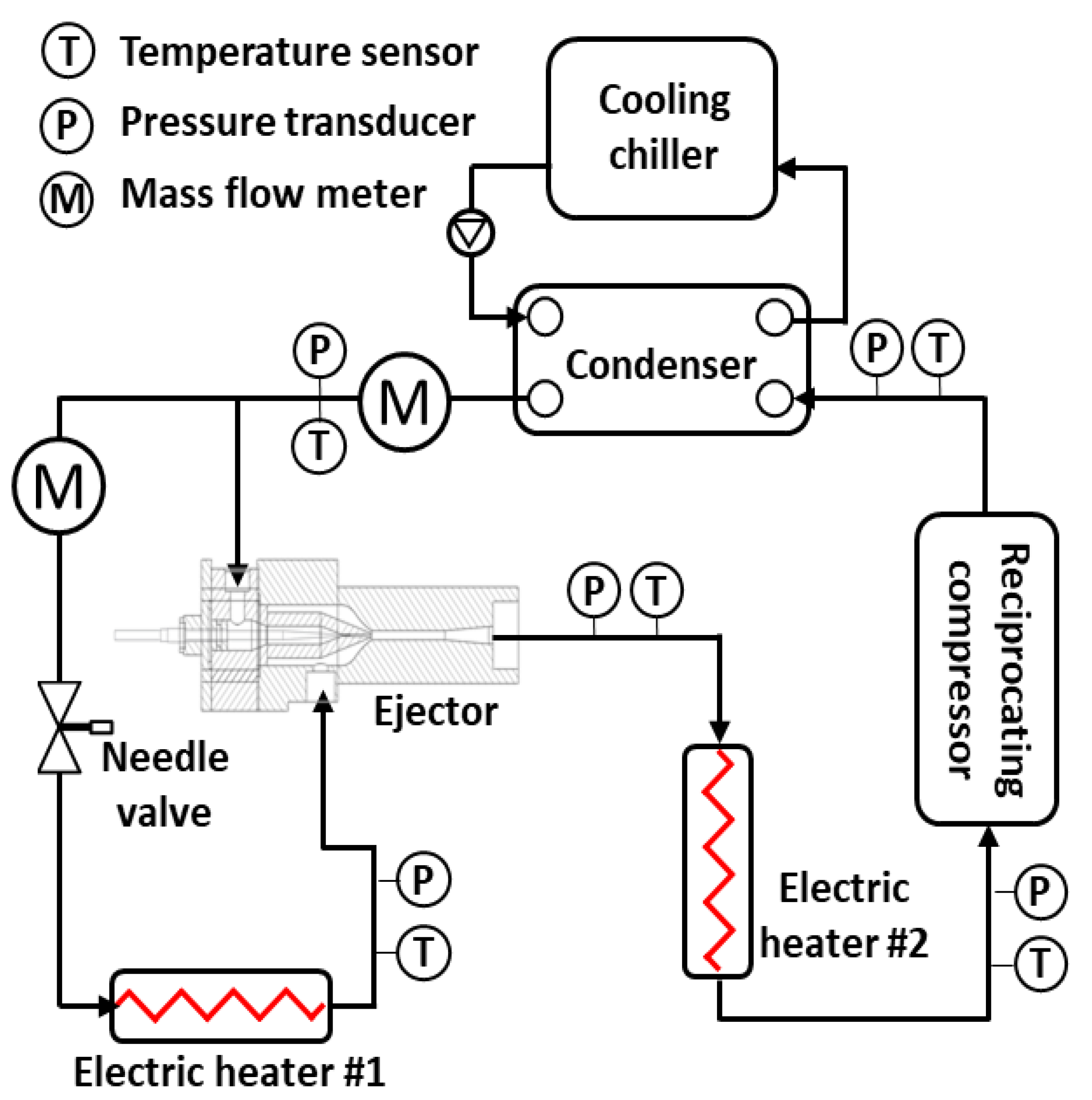
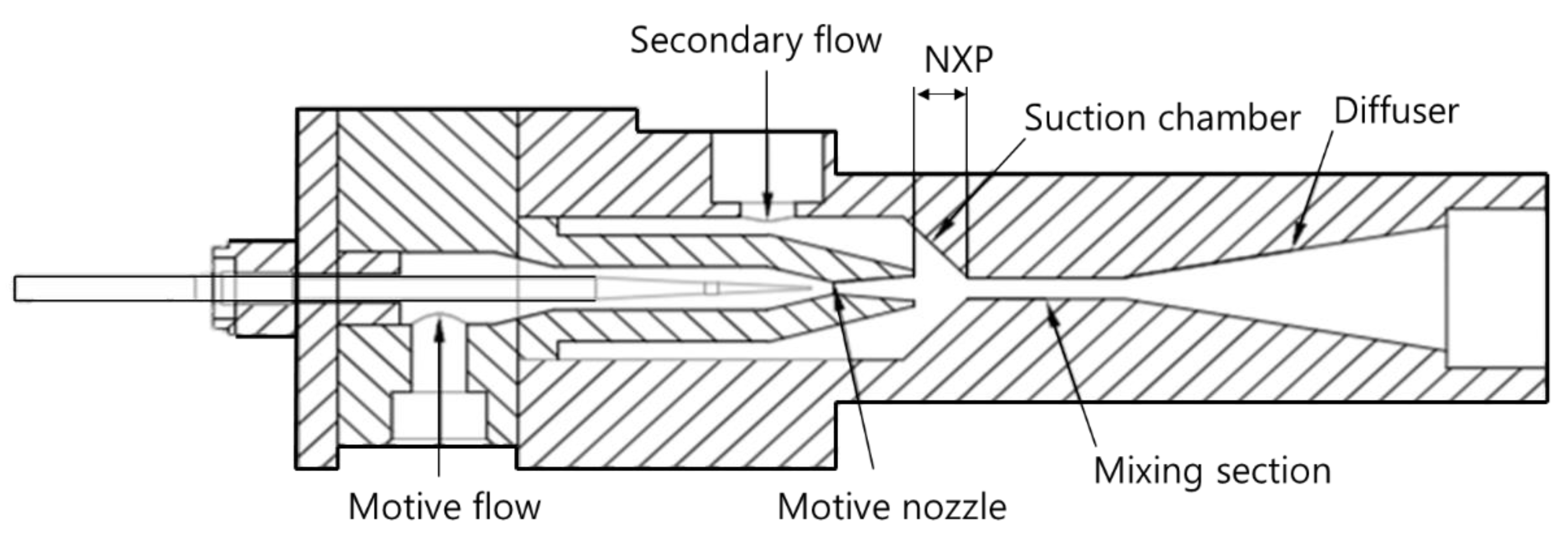
2.1. Experimental Setup

A schematic of the experimental setup for the COS ejector cycle is shown in Figure 2. The experimental setup was based on R600a and built to measure the performance characteristics of the COS ejector cycle. The main components of the experimental setup of the COS ejector cycle include a compressor, a condenser, an expansion device, an ejector, and two evaporators with different evaporating temperatures. A double-pipe heat exchanger employing cooling water was used as a condenser, which was connected to a vapor-compression chiller for condensation. The condensing temperature and capacity were controlled by the flow rate and temperature of the cooling water from the chiller. A needle valve was used for refrigerant expansion, which was located before the low-temperature evaporator. Cartridge-type electric immersion heaters, capable of producing heat at a rate of up to 300 W, were used as evaporators and installed at the secondary loop and ejector outlet. The temperature of the evaporator outlet was adjusted precisely using a digital thermostat with a controller. Two flow meters were located at the outlet of the condenser to measure the total and motive refrigerant mass flow rates. The mass flow rate at the condenser outlet was obtained using a Coriolis force mass flow meter with an accuracy of ±0.2%. The pressure of the refrigerant was obtained using digital pressure transducers with accuracies of ±0.3%. The power consumption of the compressor and electric heaters was determined using a power meter with an accuracy of 0.2%. The temperature of each point was collected using calibrated T-type thermocouples with errors of ±0.2 °C.
Figure 3 presents a schematic of the tested ejector assembly. The main components of the ejector are the motive nozzle with a spacer and needle, suction chamber, mixing section, and diffuser. Various combinations of ejector design can be easily changed due to the modular design. The NXP, which is the distance between the motive nozzle and the mixing section, was controlled through a spacer. The spacer is located between the motive nozzle module and the ejector main body module. In addition, the diameter of the motive nozzle was controlled using the needle of the motive nozzle. The needle of the motive nozzle and needle valve control the evaporating pressure and ER. Table 1 summarizes the component specifications of the COS ejector cycle and the tested ejector.

2.2. Test Procedure and Data Reduction

The test conditions for the COS ejector cycle experiment are listed in Table 2. Compressor speed is a parameter that affects the refrigerant flow rate and compression efficiency of the cycle. In the experiment, compressor speed was varied within the range of 25–45 rps at intervals of 10 rps using an inverter driver, in order to analyze the effect on the compression efficiency and total mass flow rate of the COS ejector cycle. The ER is a critical parameter influencing the cooling capacity ratio of each evaporator. ERs ranging from 0 to 0.6 were selected to investigate the effect of the ejector as the mass flow rate of the motive flow decreased. The NXP was adjusted by inserting a spacer within the range of −3–6 mm at 3 mm intervals. A negative value for the NXP indicates that the tip of the motive nozzle is located past the mixing section inlet. For the experiments, the condensing and evaporating pressures were determined to be 500 and 70 kPa, respectively, i.e., the same pressures used for common household refrigeration cycles driven by R600a. In addition, the COS ejector cycle was tested at an optimum quantity of 200 g of refrigerant; based on an optimal charging experiment, this amount achieved the highest performance for the COS ejector cycle under standard testing conditions.
To evaluate the ejector cycle performance, two parameters—ER and PLR—were used. As indicated in Equation (1), ER represents the ratio of the motive and secondary mass flow rates and ER is an important performance parameter for calculating the cooling capacity and ejector cycle performance, where m ˙ s is the mass flow rate of the secondary flow (kg h−1), and m ˙ mot is the mass flow rate of the motive flow (kg h−1):
E R = m ˙ s m ˙ m o t
As expressed in Equation (2), PLR is also important performance parameter for evaluating the ejector cycle performance. The PLR represents the ratio of the pressure at the secondary flow to that at the ejector outlet flow, where Ps is the secondary inlet flow pressure (kPa), and Pd is the ejector outlet flow pressure (kPa):
P L R ( % ) = P d P s P s × 100
ER and PLR have a significant effect on the COP of the COS ejector cycle. To define the COP of the COS ejector cycle, its cooling capacity was calculated according to the input and output enthalpies of each evaporator and the mass flow rates passing through each evaporator. The cooling capacity and COP were evaluated using Equations (3) and (4), respectively; in these expressions, heva.in and heva.out represent the inlet and outlet enthalpies of the evaporator, respectively, and m ˙ is the total mass flow rate. The COP was evaluated as the ratio of the total cooling capacity, which is the sum of the cooling capacity of the two evaporators applied to the compressor work for compression,
Q ˙ = m ˙ ( h e v a . o u t h e v a . i n )
C O P = Q ˙ l o w + Q ˙ h i g h W
The uncertainties of the mass flow rate, compressor work, pressure, and temperature were calculated by combining the absolute error and standard deviation. Based on the systematic error of each sensor, the uncertainties of the cooling capacity, PLR, and COP of the COS ejector cycle were ±2.1%, ±1.1%, and ±2.7%, respectively, which were estimated using a single sample analysis [27].

3. Results and Discussion

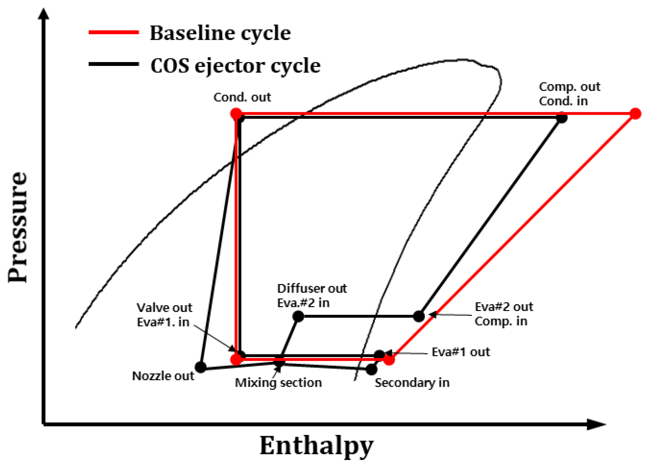
3.1. Effects of Compressor Speed on the COS Ejector Cycle

Figure 4 presents the PLR of the COS ejector cycle, according to the NXP, for various compressor speeds at ER = 0.3. The changes in PLR with respect to NXP increased as the compressor speed increased. In addition, the PLR increased with the compressor speed over the entire range of the NXP. Moreover, as the compressor speed increased, the expansion loss of the total COS ejector cycle was increased; subsequently, the PLR increased with the compressor speed owing to the increase in potential ejector effects. The highest PLRs for compressor speeds of 25, 35, and 45 rps were observed at the NXPs of 0, 3, and 3 mm, respectively. In addition, when the NXP was less than 0 mm, a low PLR was observed under all compressor speeds. A low NXP indicates that the space in the suction section is narrowed, causing a pressure drop in the secondary flow. The optimum NXP, which corresponds to the maximum PLR, tended to increase with an increase in the compressor speed at ER = 0.3. This is because additional space is required inside the suction section as the compressor speed increases, owing to the increased mass flow rate. However, an increased NXP implies a greater distance from the inlet of the mixing section; as a result, when the NXP increased beyond the maximum point of the PLR, the PLR decreased owing to the significant decrease in energy conversion of the motive flow. In addition, it was found that the change in the NXP has a significant impact on the PLR of the COS ejector cycle even when the ER was fixed.

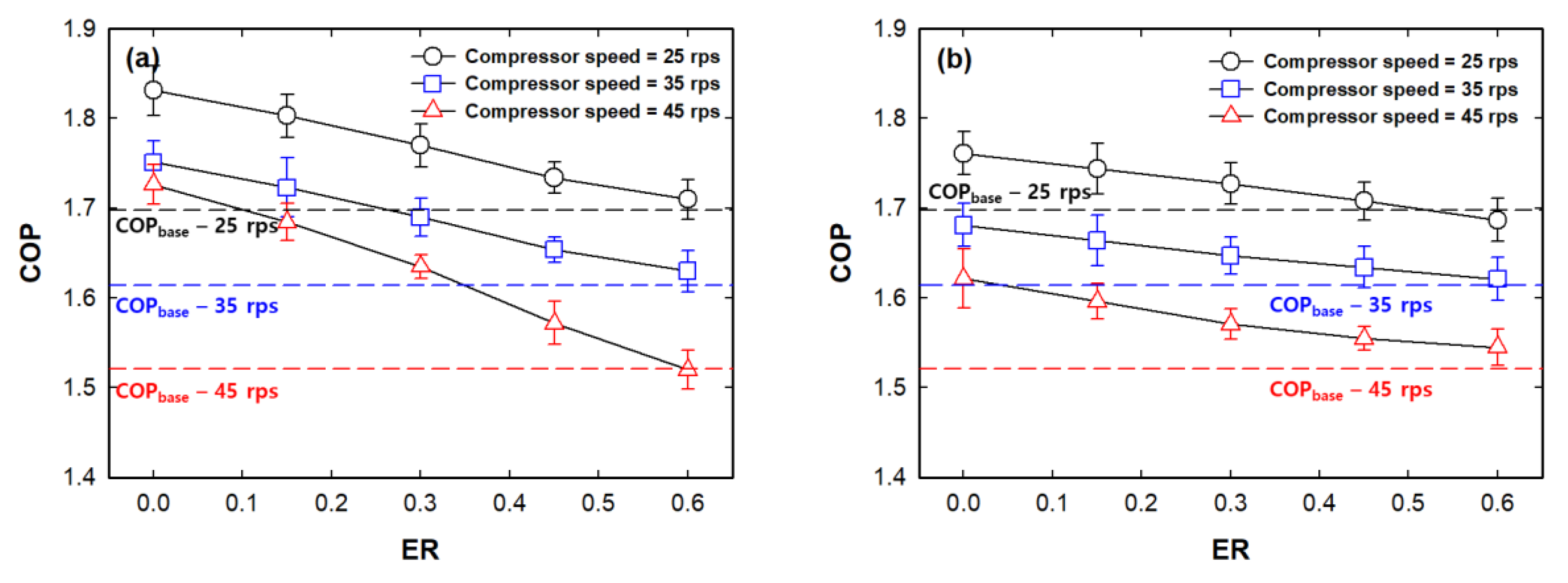
3.2. Effects of ER on the COS Ejector Cycle

Figure 5 depicts the variations in the PLR of the COS ejector cycle according to the NXP for various compressor speeds under (a) low and (b) high ER conditions. Under a low ER (0.15), as shown in Figure 5a, the highest PLR was achieved at high compressor speeds over the entire range of the NXP. The maximum PLRs were achieved at an NXP of 0 mm under all compressor speed conditions; this was attributed to the effective transmission of the kinetic energy of the refrigerant flow in the motive nozzle under this configuration. A low PLR was observed at the higher condition (NXP of 6 mm), as compared to that at the considerably lower condition (NXP of −3 mm). This is because, when the ER is low, the secondary mass flow rate is low; consequently, even if the cross-sectional area of the suction section is reduced owing to a low NXP, the influence of the internal pressure drop will be insignificant. However, under a high ER (0.6), as shown in Figure 5b, all PLR values are lower than those under low ER conditions. This can be explained by the decrease in the energy conversion owing to a reduction in the mass flow rate of the motive flow when the ER increases. In addition, for a low ER, the higher the compressor speed, the higher is the PLR. However, this was not true when the ER was high. For compressor speeds of 25, 35, and 45 rps, the maximum PLRs were achieved at the NXPs of 0, 3, and 6 mm, respectively. This indicates that the optimum NXP increased with the compressor speed under a high ER because additional space in the suction section was required.
Figure 6 presents the COP variations of the baseline cycle and the COS ejector cycle according to the NXP for various compressor speeds under (a) low and (b) high ER conditions. As the PLR increases, the compression ratio decreases and the cooling capacity increases, thereby improving the COP. Unlike the PLR, a high COP was observed at a low compressor speed under all NXP conditions. This is attributed to the decrease in the total mass flow rate, which increases cycle efficiency and reduces expansion loss. Under a low ER (0.15), as shown in Figure 6a, maximum COPs were achieved at an NXP of 0 mm under all compressor speed conditions. In addition, compared to the high ER condition, the reduction in the COP with an increase in the NXP was significant under low ER conditions. This was caused by the significant decrease in the PLR as the NXP increased beyond the optimum value, as shown in Figure 6a. However, under a high ER (0.6), as shown in Figure 6b, the optimum NXP for the maximum COP increased as the compressor speed increased, thereby reducing the internal pressure drop inside the ejector owing to an increase in the secondary flow. In particular, under NXP of −3 condition, COP of the COS ejector cycle was lower than baseline in all compressor speed conditions. For compressor speeds of 25, 35, and 45 rps, the maximum COPs were achieved at NXPs of 0, 3, and 6 mm, respectively. Moreover, when the ER is low, a COS ejector cycle with a low NXP is preferred. In contrast, when the compressor speed and ER are high, a higher NXP is preferred to ensure a high COP, thereby avoiding the internal pressure drop.

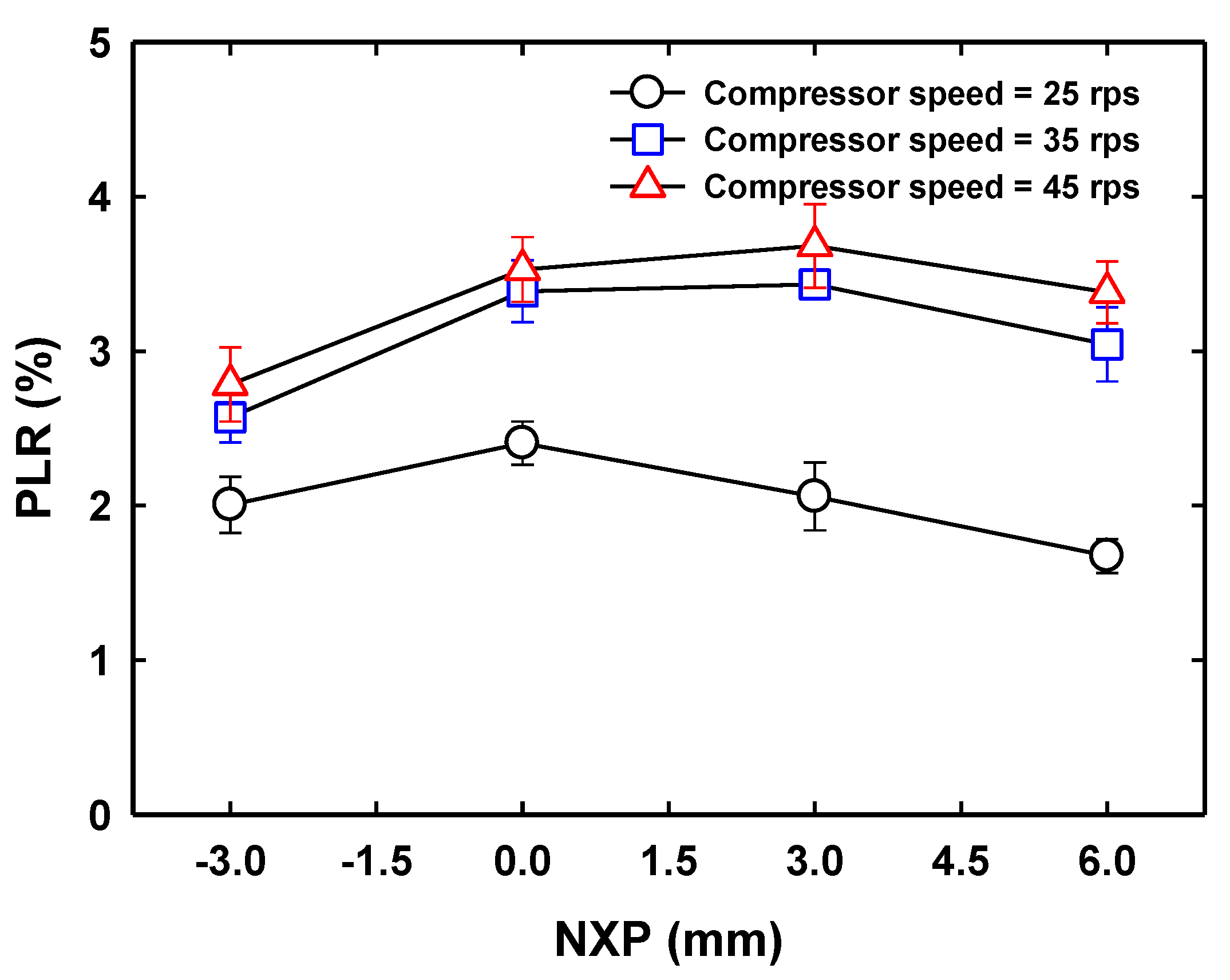
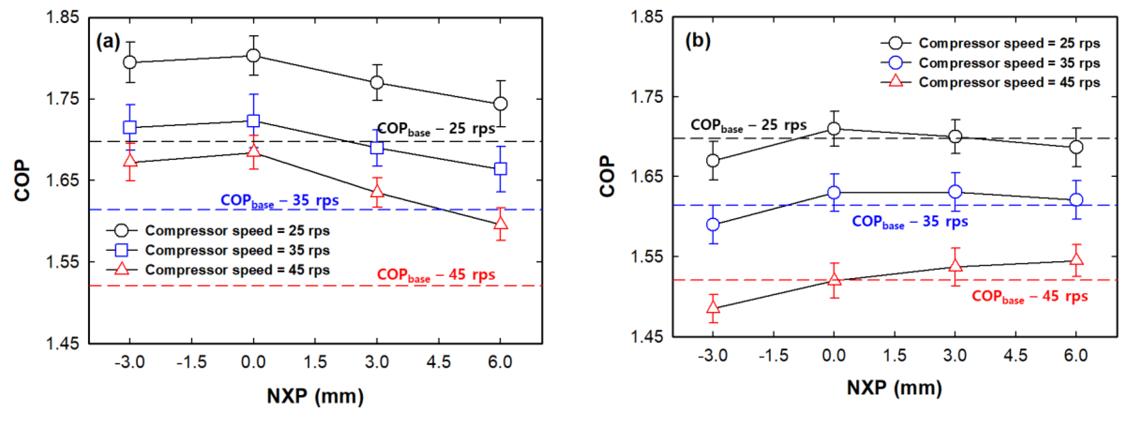
3.3. Effects of NXP on the COS Ejector Cycle

Variations in the PLR of the COS ejector cycle for various compressor speeds at NXPs of (a) 0 and (b) 6 mm are depicted in Figure 7; these NXPs of 0 and 6 mm are optimal under low and high ER conditions, respectively. As can be seen, the PLR decreased as the ER increased, because the motive mass flow rate decreased and the energy conversion between the motive and secondary flows inside the ejector decreased. The largest difference in the PLR with respect to the ER was observed at a compressor speed of 45 rps. The variations in the PLR according to the ER increased under low NXP conditions, as shown in Figure 7a, because the space that the secondary flow can pass through decreases with a decrease in the NXP. For a low ER and an NXP of 0 mm, the PLR increased with an increase in compressor speed because of the increase in the mass flow rate of the motive flow. However, for a high ER and an NXP of 0 mm, a high compressor speed resulted in low PLRs, even dropping below zero. This indicates that the effect of pressure lifting is less significant than that of the pressure drop inside the ejector. At an NXP of 6 mm, as shown in Figure 7b, the PLR decreases with respect to the increase in ER; however, the variation in the PLR with respect to the ER decreases because there is sufficient space for the suction section. In addition, although the overall PLR was reduced compared to that in Figure 7a, the PLR could be further reduced according to the ER, particularly at a compressor speed of 45 rps. In summary, on increasing the ER, the PLR decreases rapidly at low NXP conditions.
Figure 8 presents the compares the COP variations of the baseline cycle and the COS ejector cycle according to the ER, for various compressor speeds at NXPs of (a) 0 and (b) 6 mm. For all compressor speeds and NXPs, the COP of the COS ejector cycle decreases as the ER increases because the PLR decreases with such an increase. When the PLR decreases, the pressure in the compressor inlet decreases, resulting in a decrease in the cooling capacity and compression efficiency. The difference in the COP according to the ER increases under low NXP conditions, as shown in Figure 8a, owing to the large variation in the PLR. At compressor speed of 45 rps and ER of 0.6 condition, COP of the COS ejector cycle was lower than that of the baseline cycle. At an NXP of 6 mm, as shown in Figure 8b, the overall COP was lower than that in Figure 8a; however, the decrease in COP could be reduced by increasing the compressor speed and ER. In particular, when the ER was high and the compressor speed was 45 rps under high NXP conditions, the COP was higher than that under low NXP conditions. Overall, when the compressor speed and ER are low, a COS ejector cycle with a low NXP is preferred for performance improvements under this configuration. However, when the compressor speed and ER are high, a COS ejector cycle with a high NXP is preferred. When the NXP decreases, additional kinetic energy of the motive flow can be effectively transmitted; hence, the COP is improved as the PLR increases. However, when the compressor speed and ER are high, the internal pressure drop in the ejector, especially in the suction section, increases. To address this, the NXP must be increased to secure sufficient internal space required to realize a high PLR and COP.

4. Conclusions

This study investigated the effects of the NXP on a small-sized COS ejector cycle using R600a as the refrigerant based on the PLR and COP under various operating conditions, including the compressor speed and ER. The performance characteristics of the COS ejector cycle was measured by varying ER, compressor speed, and NXP. In addition, the optimum NXP of the COS ejector cycle for a small-sized household refrigeration cycle was determined to achieve the maximum PLR and COP according to the specified operating conditions. As a result, the effectiveness of the COS ejector cycle was improved at a high compressor speed and low ER. In addition, it was found that varying the NXP had a significant effect on the PLR even when the ER was fixed. The COPs were maximized at an NXP of 0 mm for all compressor speeds under low ER conditions. For compressor speeds of 25, 35, and 45 rps, the COPs were maximized at NXPs of 0, 3, and 6 mm, respectively, under high ER conditions. When the low NXP, kinetic energy transfer from the motive flow increased, and the COP improved as the PLR increased. However, the higher the ER and compressor speeds, the higher is the internal pressure drop in the ejector, particularly in the suction section. Thus, the NXP should be increased to ensure sufficient internal space to realize a high PLR and COP. In conclusion, the optimum NXP was determined based on an analysis of both the PLR and COP according to the compressor speed and the ER. When the compressor speed and ER were low, a low NXP of 0 mm was determined to be optimum for maximizing the PLR and COP; in contrast, when the compressor speed and ER were high, a high NXP of 6 mm was found to be optimum.

Author Contributions

Conceptualization, Y.J. and J.H.A.; Methodology, Y.J. and H.K.; Formal Analysis, Y.J. and H.K.; Investigation, Y.J. and S.K.; Writing—Original Draft Preparation, Y.J.; Writing—Review and Editing, J.H.A and S.K.; All authors have read and agreed to the published version of the manuscript.

Funding

This work was supported by the National Research Foundation of Korea (NRF) grant funded by the Korea government (MSIT) (No. NRF-2019R1G1A1099288), and the main research program (E0187302-03) of the Korea Research Food Institute (KFRI).

Acknowledgments

This work was supported by the National Research Foundation of Korea (NRF) grant funded by the Korea government (MSIT) (No. NRF-2019R1G1A1099288), and the main research program (E0187302-03) of the Korea Research Food Institute (KFRI).

Conflicts of Interest

The authors declare no conflict of interest. The funders had no role in the design of the study; in the collection, analyses, or interpretation of data; in the writing of the manuscript, or in the decision to publish the results.

Abbreviations

COPcoefficient of performance.
COScondenser outlet split
ERentrainment ratio
PLRpressure lifting ratio
NXPnozzle exit position

Nomenclature

compcompressor
condcondenser
hspecific enthalpy (kJ Kg−1)
m ˙ mass flow rate (kg h−1)
Ppressure (kPa)
Q ˙ cooling capacity (W)
W compressor work (W)
Subscripts
evaevaporator
highhigh-temperature evaporator
ininlet
lowlow-temperature evaporator
motmotive
outoutlet
ssecondary

References

  1. Cheng, W.L.; Yuan, X.D. Numerical analysis of a novel household refrigerator with shape-stabilized PCM (phase change material) heat storage condensers. Energy 2013, 59, 265–276. [Google Scholar] [CrossRef]
  2. Yang, M.; Jung, C.; Kang, Y. Development of high efficiency cycles for domestic refrigerator-freezer application. Energy 2015, 93, 2258–2266. [Google Scholar] [CrossRef]
  3. Jeon, Y.; Lee, S.; Kim, W.; Jung, J.; Kim, Y. Numerical study on the optimal design of injection-hole geometries of a twin rotary compressor in a liquid injection heat pump. Appl. Them. Eng. 2017, 25, 1178–1188. [Google Scholar] [CrossRef]
  4. Sun, Z.C.; Ma, X.; Ma, L.X.; Li, W.; Kukulka, D. Flow boiling heat transfer characteristics in horizontal, three-dimensional enhanced tubes. Energies 2019, 12, 927. [Google Scholar] [CrossRef] [Green Version]
  5. Jeon, Y.; Kim, D.; Jung, J.; Jang, D.S.; Kim, Y. Comparative performance evaluation of conventional and condenser outlet split ejector-based domestic refrigerator-freezers using R600a. Energy 2018, 161, 1085–1095. [Google Scholar] [CrossRef]
  6. Jeon, Y.; Kim, S.; Kim, D.; Chung, H.J.; Kim, Y. Performance characteristics of an R600a household refrigeration cycle with a modified two-phase ejector for various ejector geometries and operating conditions. Appl. Energy 2017, 205, 1059–1067. [Google Scholar] [CrossRef]
  7. Aridhi, E.; Albouchi, A.; Mami, A. Observability and controllability study of a household refrigerator exposed to an outdoor cold airflow using bond graph approach. Int. J. Air-Cond. Refrig. 2017, 25, 175001. [Google Scholar] [CrossRef]
  8. Nguyen, M.P. Overall optimization and exergy analysis of an air conditioning using a series-series conunterflow arrangement of water chillers. Int. J. Air-Cond. Refrig. 2019, 27, 1950034. [Google Scholar]
  9. Shabgard, H.; Bergman, T.; Sharifi, N.; Faghri, A. High temperature latent heat thermal energy storage using heat pipes. Int. J. Heat Mass Transf. 2010, 53, 2979–2988. [Google Scholar] [CrossRef]
  10. Esarte, J.; Blanco, J.; Bernardini, A.; San-José, J. Optimizing the design of a two-phase cooling system loop heat pipe: Wick manufacturing with the 3D selective laser melting printing technique and prototype testing. Appl. Them. Eng. 2017, 111, 407–419. [Google Scholar] [CrossRef]
  11. Gay, N. Refrigerating System. U.S. Patent Application Publication US183 1931. [Google Scholar]
  12. Elbel, S.; Hrnjak, P. Flash gas bypass for improving the performance of transcritical R744 systems that use microchannel evaporators. Int. J. Refrig. 2004, 27, 724–735. [Google Scholar] [CrossRef]
  13. Chen, W.; Shi, C.; Zhang, S.; Chen, H.; Chong, D.; Yan, J. Theoretical analysis of ejector refrigeration system performance under overall modes. Appl. Energy 2017, 185, 2074–2084. [Google Scholar] [CrossRef]
  14. Macia, L.; Castilla, R.; Gamez-montero, P.J.; Camacho, S.; Codina, E. Numerical simulation of a supersonic ejector for vacuum generation with explicit and implicit solver in open foam. Energies 2019, 12, 3553. [Google Scholar] [CrossRef] [Green Version]
  15. Shovon, M.; Kumar, R.; Kim, T.; Kim, H. Study on the conceptual design of a solar ejector refrigeration system. Int. J. Air-Cond. Refrig. 2020, 28, 2030001. [Google Scholar] [CrossRef]
  16. He, Y.; Deng, J.; Li, Y.; Ma, L. A numerical contrast on the adjustable and fixed trancritical CO2 ejector using exergy flux distribution analysis. Energy Convers. Manag. 2019, 196, 729–738. [Google Scholar] [CrossRef]
  17. Bodys, J.; Smolka, J.; Banasiak, K.; Palacz, M.; Haida, M.; Nowak, A.J. Performance improvement of the R744 two-phase ejector with an implemented suction nozzle bypass. Int. J. Refrig. 2018, 90, 216–228. [Google Scholar] [CrossRef] [Green Version]
  18. Jeon, Y.; Jung, J.; Kim, D.; Kim, S.; Kim, Y. Effects of ejector geometries on performance of ejector-expansion R410A air conditioner considering cooling seasonal performance factor. Appl. Energy 2017, 205, 761–768. [Google Scholar] [CrossRef]
  19. Lawrence, N.; Elbel, S. Experimental investigation of a two-phase ejector cycle suitable for use with low-pressure refrigerants R134a and R1234yf. Int. J. Refrig. 2014, 38, 310–322. [Google Scholar] [CrossRef]
  20. Oshitani, H.; Yamanaka, Y.; Takeuchi, H.; Kusano, K.; Ikegami, M.; Takano, Y.; Ishizaka, N.; Sugiura, T. Vapor Compression Cycle Having Ejector. U.S. Patent Application Publication US 2005/0268644 A1.
  21. Lawrence, N.; Elbel, S. Theoretical and practical comparison of two-phase ejector refrigeration cycles including first and second law analysis. Int. J. Refrig. 2013, 36, 1220–1232. [Google Scholar] [CrossRef]
  22. Kim, S.; Jeon, Y.; Chung, H.J.; Kim, Y. Performance optimization of an R410A air-conditioner with a dual evaporator ejector cycle based on cooling seasonal performance factor. Appl. Energy 2018, 131, 988–997. [Google Scholar] [CrossRef]
  23. Palacz, M.; Smolka, J.; Kus, W.; Fic, A.; Bulinski, Z.; Nowak, A.; Banasiak, K.; Hafner, A. CFD-based shape optimization of a CO2 two-phase ejector mixing section. Appl. Them. Eng. 2016, 95, 62–69. [Google Scholar] [CrossRef]
  24. Wang, C.; Wang, L.; Wang, X.; Zhao, H. Design and numerical investigation of an adaptive nozzle exit position ejector in multi-effect distillation desalination system. Energy 2017, 140, 673–681. [Google Scholar] [CrossRef]
  25. Wu, H.; Liu, Z.; Han, B.; Li, Y. Numerical investigation of the influences of mixing chamber geometries on steam ejector performance. Desalination 2014, 353, 15–20. [Google Scholar] [CrossRef]
  26. Yan, J.; Li, S.; Liu, Z. Numerical investigation on optimization of ejector primary nozzle geometries with fixed/varied nozzle exit position. Appl. Them. Eng. 2020, 175, 115426. [Google Scholar] [CrossRef]
  27. Taylor, B.N.; Kuyatt, C.E. Guidelines for Evaluating and Expressing the Uncertainty of NIST Measurement Results; NIST Technical Note 1297; NIST: Gaithersburg, MD, USA, 1994. [Google Scholar]
Figure 1. Pressure–enthalpy diagrams of the baseline cycle and the condenser outlet split (COS) ejector cycle.
Energies 13 05160 g001
Figure 2. Schematic of the experimental setup of the COS ejector cycle.
Energies 13 05160 g002
Figure 3. Cross-sectional diagram of a tested ejector.
Energies 13 05160 g003
Figure 4. Variations in pressure lifting ratio (PLR) according to nozzle exit position (NXP) for variations in compressor speed at an ER of 0.3.
Energies 13 05160 g004
Figure 5. Variations in PLR according to NXP for various compressor speeds at an ER of (a) 0.15 and (b) 0.6.
Energies 13 05160 g005
Figure 6. Variations in COP according to NXP for various compressor speeds at an ER of (a) 0.15 and (b) 0.6.
Energies 13 05160 g006
Figure 7. Variations in PLR according to ER for various compressor speeds at NXPs of (a) 0 and (b) 6 mm.
Energies 13 05160 g007
Figure 8. Variations in COP according to ER for various compressor speeds at NXPs of (a) 0 and (b) 6 mm.
Energies 13 05160 g008
Table 1. Specifications of system components and tested ejector.
ComponentVariableValues
CompressorTypeReciprocating
Cylinder volume1.531 × 105 m3
Working fluidR600a
CondenserTypeCoaxial double pipe
Length2.07 m
Diameter1.27 × 10−2 m
Rated capacity500 W
EvaporatorTypeCartridge (insert)
Rated capacity300 W
Needle valveOrifice diameter1.19 × 103 m
EjectorNozzle throat diameter8.5 × 10−4 m
Nozzle outlet diameter9.7 × 10−4 m
NXP−3–6 mm
Mixing section diameter3.0 mm
Mixing section length36 mm
Diffuser angle
Table 2. Test conditions in the present study.
Operating ConditionRangeInterval
Compressor speed (rps)25–4510
ER0–0.60.15
NXP (mm)−3–63
Condensing pressure (kPa)500
Evaporating pressure (kPa)70
Subcooling (°C) 3
Superheat (°C)5

