Article

Design and Analysis of a Linear Memory Machine for Ocean Wave Power Generation

1
College of Information Science and Engineering, Huaqiao University, Xiamen 361021, China
2
Shenzhen in Drive Amperex Co. Ltd., Shenzhen 300750, China
3
Department of Electrical Engineering, The Hong Kong Polytechnic University, Hong Kong, China
*
Author to whom correspondence should be addressed.
Energies 2020, 13(19), 5216; https://doi.org/10.3390/en13195216
Submission received: 3 August 2020 / Revised: 18 September 2020 / Accepted: 5 October 2020 / Published: 7 October 2020
(This article belongs to the Section A3: Wind, Wave and Tidal Energy)

Abstract

:
In this paper, a permanent magnet (PM) linear memory machine is proposed for ocean wave power generation. A notable feature of this machine is its online tunable mnemonic flux. This enables it to operate efficiently in a wide speed range and makes it suitable for the variable-speed wave-power generation. Moreover, this machine has both the PMs and the windings arranged in its stator so that it does not need slip rings or brushes. The proposed machine is also robust and cost-effective because it has a simple translator of slotted steel. In this paper, the configuration and working principle of the linear memory machine are firstly introduced. The results of a parametric analysis are presented to investigate the effects of the proposed machine’s geometric parameters. The performance of the proposed machine is then analyzed using time-stepping finite element method (TS-FEM).

1. Introduction

Among the various energy resources, ocean wave energy is very promising since it is renewable, green, enormous, and widely accessible. Wave energy also has a higher density than many other popular renewable energy resources, such as wind or solar energy [1]. These merits have motivated people to develop energy converters to exploit wave energy. In the literature, many energy converters have been proposed for wave power generation. Most early wave energy converters first convert the wave energy into other forms such as potential, hydraulic, or pneumatic energy, and then generate electrical power using rotary generators [2,3,4,5,6,7]. These systems are often bulky and less robust due to the dual/multistep conversion process. In recent years, more and more direct-drive energy converters, which extract power directly from the reciprocating wave motion, have been proposed. In these direct-drive energy converters, the linear-to-rotary conversion process can be eliminated, improving the system performance.
A direct-drive wave energy converter can be realized by connecting the translator of a linear machine to a floating buoy, as shown in Figure 1 [8,9]. The relative motion between the stator and the translator is used to extract energy from the ocean waves. This relative motion needs to be maximized for effective power extraction. The machine is therefore installed on the seabed. As the wave speed is usually about 1 m/s, the thrust force of the converter needs to be large. The permanent magnet (PM) linear machines are a good choice for these systems since they have the inherent merits of high force density and high efficiency. However, wave energy has significant seasonal variability [10,11]. The average power from a wave energy device in winter can be 6 times more than the average power from the same device in summer [12]. Conventional PM machines are not as good in variable-speed operations because their airgap flux is hard to adjust. The wave motion varies from time to time, and the application of PM linear machines in wave energy converters is therefore limited.
Recently, memory machines have been drawing attention because of their impressive flux controllability [13]. Unlike the conventional PM machines that have constant PM fields, memory machines have variable flux with online de- and re-magnetization. Memory machines usually use AlNiCo alloy as the PM. Its magnetization level can be changed by a short excitation current pulse. In conventional PM machines, the flux weakening operation requires a continuous demagnetization current and causes additional losses. In comparison, the current pulse for flux adjustment in a memory machine does not cause significant losses. The machine can therefore be power-efficient in a wide speed range.
The mnemonic flux concept is hard incorporate into conventional rotor/translator PM machines due to the airgap between the PMs and the windings. If the magnetization winding is placed in the rotor/translator, slip rings and brushes will be required. In [14,15], flux mnemonic doubly salient machines are proposed. In these machines, both the PMs and the windings are embedded in the stator so that they do not need slip rings or brushes. However, the doubly salient structure has relatively low torque/force density and large cogging.
In this paper, a novel linear memory machine is proposed for ocean wave power generation. A key point of the machine is the so-called flux modulation (FM) effect, which refers to its ability to perform energy conversions via a harmonic magnetic field. Utilizing the FM effect, this machine managed to embed the PMs, AC windings, and DC windings in its short stator. Its flux can be easily tuned without needing slip rings or brushes. The relatively long translator has a simple structure of slotted silicon steel laminations, making the machine robust and cost-effective. The low-coercivity AlNiCo alloy was used for its PM in order to realize mnemonic flux. The machine can operate effectively in a wide speed range, making it suitable for wave energy conversion in which the wave velocity varies from time to time. In this paper, the structure and working principle of the proposed machine are explained first. The design considerations are then introduced. The performance of the proposed machine as well as the flux regulation operation are analyzed and showcased using time-stepping finite element method (TS-FEM).

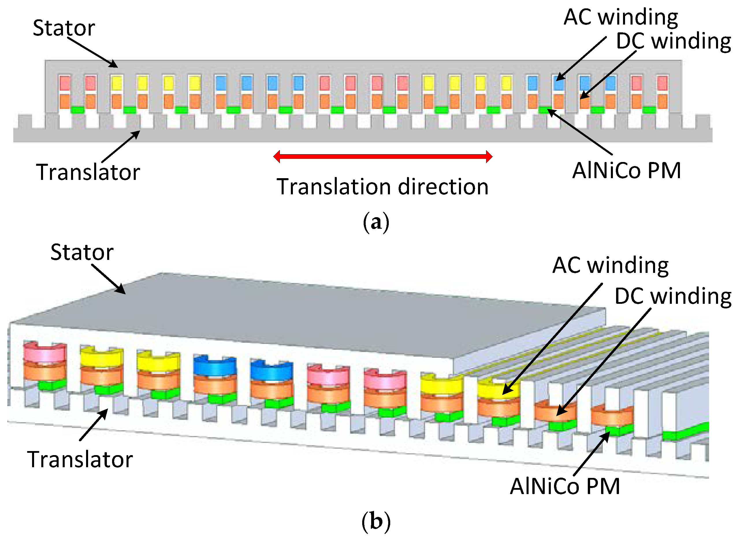
2. Proposed Machine Configuration and Operation Principle

2.1. Flux Modulation
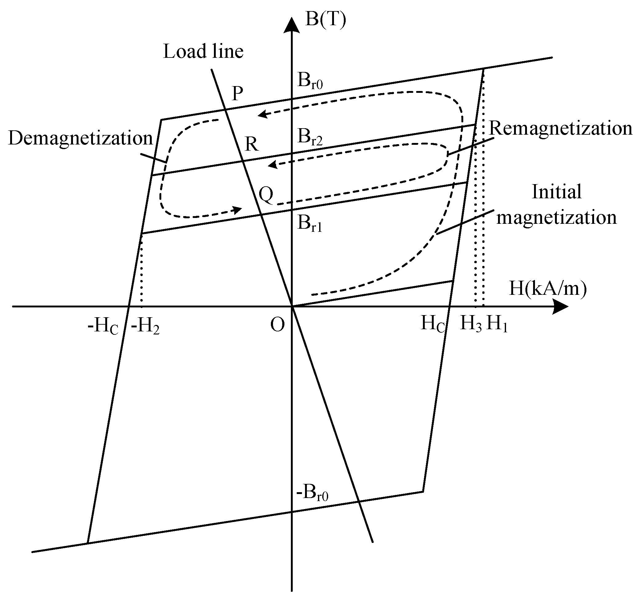
The configuration of the proposed machine is shown in Figure 2. The stator has two sets of windings, namely the AC armature winding and the DC magnetizing winding. Both windings are housed in the open slots of the stator. The AlNiCo PMs are mounted on top of every other stator tooth, and they are magnetized perpendicular to the airgap. The translator has a simple structure of slotted steel. As neither windings nor PMs are placed on the relatively long translator, the machine is robust and cost-effective. The main parameters of the proposed machine are listed in Table 1.
The key working principle of the proposed machine is the flux modulation (FM) effect, which was first used in magnetic gears and then introduced to electric machines [16,17,18,19,20]. Basically, FM means to generate field harmonics by making the airgap uneven. The energy conversion can therefore be realized via certain harmonic components of the magnetic field. In the proposed machine, the fundamental component of the PM magnetomotive force (MMF) can be represented by
F F 0 + F m cos ( N p m θ + ϕ m )
where F0 is the average value of F; Fm is the magnitude of the alternating component of F; Npm is the number of the PMs on the stator; θ is the angular position; φm is the initial phase angle of Fm. We assume that the translator is moving at a speed of v in reference to the stator. Due to the existence of the stator teeth and translator teeth, the uneven airgap permeance can be represented by
λ λ 0 + λ 1 cos [ N t ( θ v t ) + ϕ 1 ] + λ 2 cos ( N s θ + ϕ 2 )
where λ0 is the average value of λ; λ1 is the magnitude of the alternating component of λ due to the translator teeth; λ2 is the magnitude of the alternating component of λ due to the stator teeth; Nt and Ns are the active translator teeth number and stator teeth number, respectively; t is the time; φ1 and φ2 are the initial phase angles of λ1 and λ2, respectively.
The airgap flux density can be calculated by multiplying F and λ:
B { λ 0 F 0 + λ 1 F 0 cos [ N t ( θ v t ) + ϕ 1 ] + λ 2 F 0 cos ( N s θ + ϕ 2 ) + λ 0 F m cos ( N p m θ + ϕ s ) + 1 2 λ 1 F m cos [ ( N t + N p m ) ( θ N t v N t + N p m t ) + ϕ 1 + ϕ m ] + 1 2 λ 1 F m cos [ ( N t N p m ) ( θ N t v N t N p m t ) + ϕ 1 ϕ m ] + 1 2 λ 2 F m cos [ ( N s + N p m ) θ + ϕ 2 + ϕ m ] + 1 2 λ 2 F m cos [ ( N s N p m ) θ + ϕ 2 ϕ m ] }
It can be seen that the flux density in the airgap has several significant components whose pole-pair numbers are Npm, Nt, Ns, Nt-Npm, Ns-Npm, Nt + Npm, and Ns + Npm. By designing the pole-pair number of the AC armature winding to be Nt-Npm, effective voltage can be induced in the armature winding. The frequency of the induced voltage can be calculated using the formula
f = N t v L t
where Lt is the effective length of the translator. Clearly, the frequency of the induced voltage in the armature winding corresponds to the pole number of the effective translator teeth. This is a notable difference between the proposed machine and a conventional PM machine. In conventional PM machines, the voltage frequency corresponds to the pole-pair number of the PMs or the armature winding.

2.2. Mnemonic Flux

In conventional PM machines, the AlNiCo PM has been widely superseded by other materials due to its low coercivity and nonlinear demagnetization curve. However, these characteristics make it possible for AlNiCo to have mnemonic flux. The low coercivity makes it easy to be magnetized or demagnetized. The nonlinear demagnetization curve enables it to remain at a different magnetization level after being magnetized or demagnetized.
For simplicity, a piecewise linear hysteresis model was used for the analysis as shown in Figure 3. It was assumed that all hysteresis loops had the same coercivity, but that their remanence values could be different. In an electric machine, as the structure and the geometries are fixed, the reluctance of the magnetic circuit is constant. As a result, the load line is straight. In the initial magnetization of the PM, if a magnetic field with a strength larger than H1 is applied, the state of the PM will go along the initial magnetization line to working point P in Figure 3, where P is the crossing point of the load line and the major hysteresis loop. If a demagnetization field with a strength of –H2 is applied after that, the state of the PM will go along the demagnetization line to working point Q. The PM state can be moved to working point R along the remagnetization line by applying a field of H3. Using this piecewise linear hysteresis model, the magnetization level and working point can be easily obtained.
The features of the proposed machine structure can be concluded as follows. (1) The PM magnetization level can be regulated online, making it suitable for variable-speed wave power generation. (2) The PMs are located in the stator together with the windings, making the magnetization or demagnetization easy to implement. The machine is also more reliable as it does not need brushes or slip rings. (3) The long translator has a simple structure of steel laminations, making it robust and cost-effective.

3. Design Considerations

To investigate the influences of the geometric parameters on the machine performance, a parametric analysis was conducted using the Maxwell 2D® package (Ansys Inc., Pittsburgh, PA, USA). The electromagnetic force component parallel to the airgap was used as an indicator of the machine performance. The analysis was conducted under the following considerations:
(1)
The current density in the winding conductors was 4 A/mm2 and the slot fill factor was 50%. As the magnetization current pulse was very short and its copper losses can be ignored, the DC winding needed only a small part of the slot area (10% in this design).
(2)
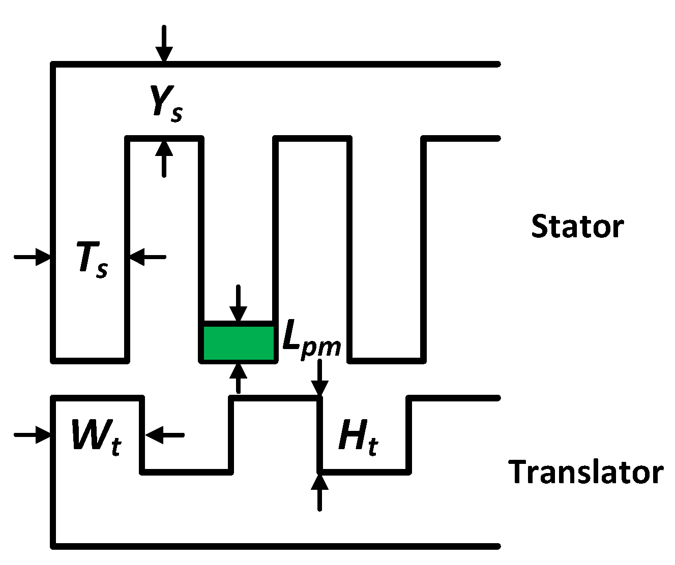
The stator yoke height YS, the stator teeth width TS, the PM length Lpm, the translator teeth width Wt, and the translator teeth height Ht were considered in the analysis, as shown in Figure 4. The initial values were as follows: YS = 4 mm, TS = 5 mm, Lpm = 2 mm, Wt = 5 mm, and Ht = 5 mm. When one variable was under analysis, the other variables were fixed at their initial values.
The parametric analysis results are shown in Figure 5. It can be seen that YS can be neither too large nor too small, for the sake of the thrust force. A large YS compressed the slot area and, hence, decreased the armature current; a small YS increased the reluctance of the flux path. The analysis result for TS was similar to that of YS. The value of Lpm influenced both the MMF and the FM effect. The increase of Lpm increased the MMF of the magnetic circuit, and it also increased the equivalent airgap length. In other words, Lpm affected the magnitudes of both F and λ in Equation (3). The width of the translator teeth Wt also influenced the magnetic reluctance and the FM effect. The analysis result of Wt showed that the thrust force was relatively large when Wt was about half the slot pitch. The value of Ht had an influence on the airgap permeance λ. The increase of Ht benefited the force performance until it reached around 5 mm. The designed values for these variables were as follows: YS = 2 mm, TS = 3 mm, Lpm = 7 mm, Wt = 5 mm, and Ht = 5 mm.

4. Performance Analysis
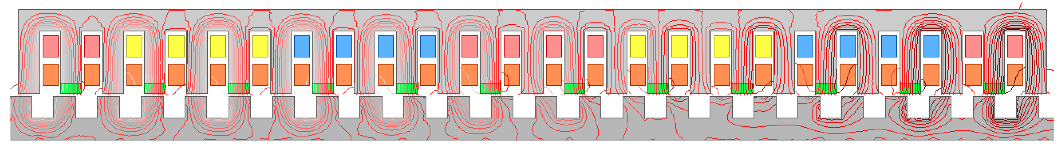
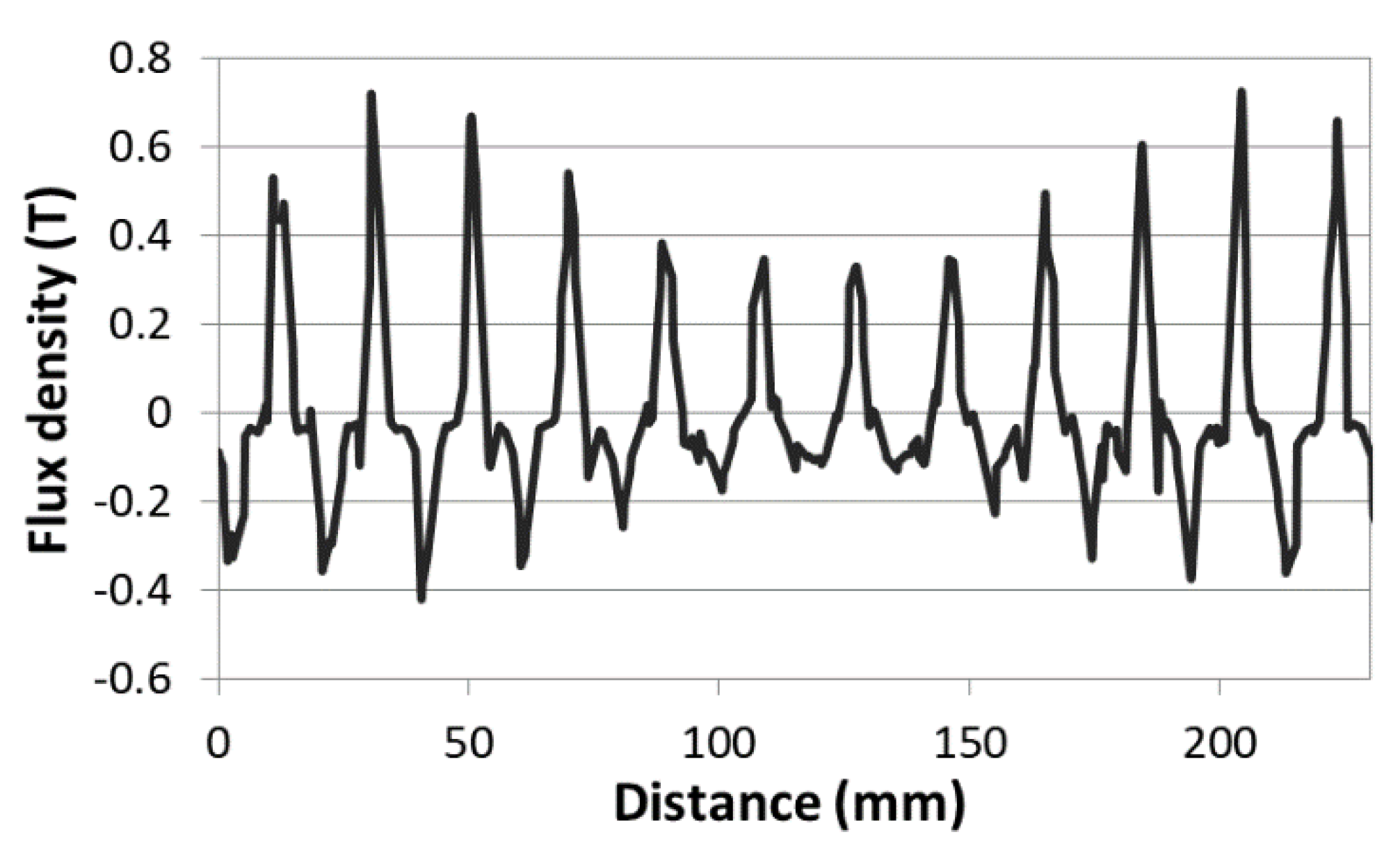
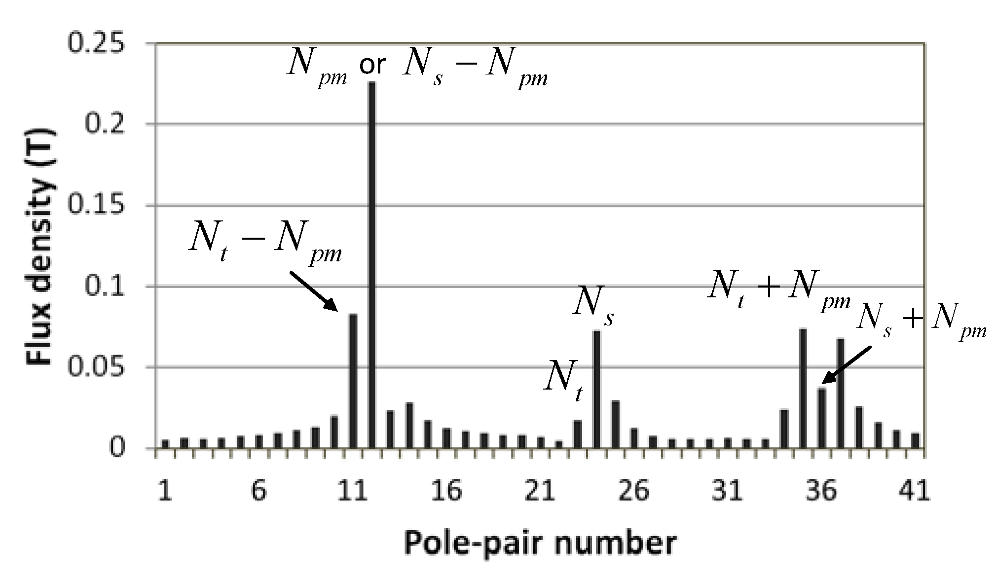
4.1. Field Analysis

Using TS-FEM, the distribution of the PM flux was analyzed as shown in Figure 6. The flux density in the airgap was plotted as shown in Figure 7. It can be seen that the fundamental component of this flux had a pole-pair number of 12, which was Npm. To further investigate the flux density, a fast Fourier transform (FFT) was conducted. The corresponding harmonic spectrum of the PM flux is shown in Figure 8. Besides the fundamental component of the PM field with Npm pole-pairs, the harmonic components with Nt-Npm, Nt, Ns, Nt + Npm, and Ns + Npm pole-pairs were also significant, which corresponded well with the analysis in Section 2.1. Among these harmonic components, Nt-Npm, Nt, and Nt + Npm were alternating components when the translator moved, which meant that they could be used for the energy conversion.

4.2. Flux Regulation

Flux regulation is key for the proposed machine to improve its performance in variable-speed operation. With the mnemonic AlNiCo PM used for its field excitation, the airgap flux of the machine can be regulated online by current pulses when the translator velocity varies. In wave energy conversion, as the translator velocity varies with the waves, it is possible to apply different PM magnetization levels in different translator velocity ranges. In this way, the output voltage of the generator can be kept relatively high or close to the rated voltage of the power electronic converter over a wider speed range.
Here we propose two flux regulation strategies. The first is to regulate flux between waves, changing the PM magnetization level when the wave height or maximum velocity changes. For example, if the PM flux is regulated according to the strategy listed in Table 2, the back electromotive force (back-EMF) at different translator velocities is shown in Figure 9. The back-EMF without flux regulation is also presented for comparison. With flux regulation, the amplitudes of the output voltage are almost the same at three different velocities. In this way, the corresponding electronic converter can operate more effectively. When the mover speed was 0.5 m/s, the frequency of the back-EMF was 50 Hz, which agrees with the theoretical analysis result in Equation (4).
The second strategy is to regulate flux within wave cycles. Considering that the translator velocity varies within a single wave, the PM flux can be tuned within wave cycles for generator performance improvement. We assume a sinusoidal wave of 1.5 m in height and 4 s in period. As the proposed machine is used in a direct-drive energy conversion system, the translator motion is similar to the wave motion [8,21]. For simplicity, we assumed these two motions to be the same. If the PM magnetization is online-tuned according to Table 2, the back-EMF in the armature windings is shown in Figure 10. It is observed that the back-EMF in the low-velocity range was improved by the flux regulation. The generator with flux regulation can output more power in a wave cycle, and it better utilized the wave energy.

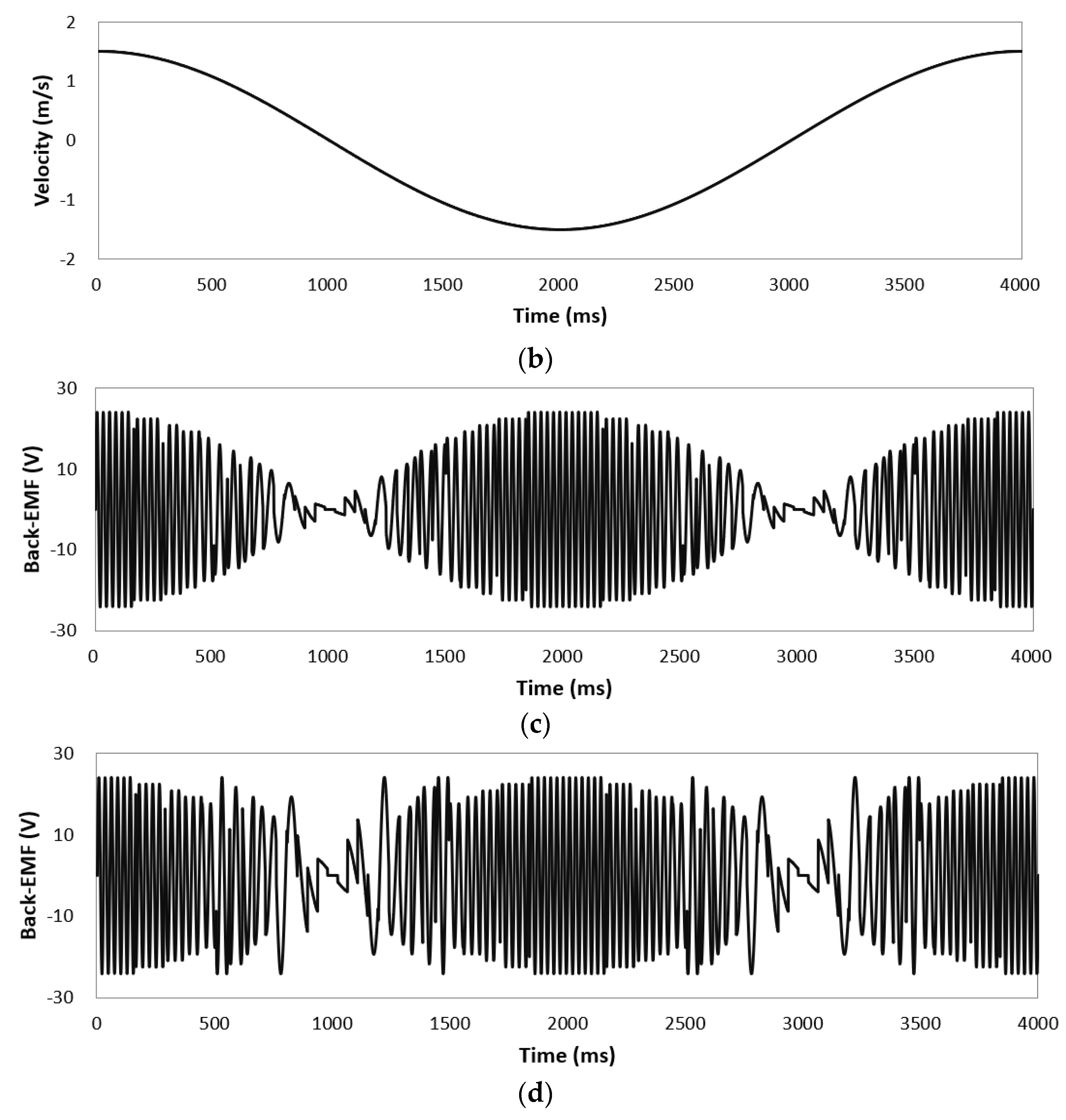
4.3. Electromagnetic Force and Efficiency

The electromagnetic force performance affects the dynamic performance of the generator system. When the translator was driven at a constant speed of 0.5 m/s and a resistive load was connected to the ends of the armature winding, the electromagnetic force along the translation direction was characterized as shown in Figure 11. A force ripple with a period of 20 ms was observed. The periodic distance of the force ripple was, hence, 10 mm, which is exactly equal to the pole pitch of the translator. Figure 11 also plots the cogging force of the generator when the winding is open-circuited. It can be deduced that the force ripple was mainly due to the cogging. In practice, the cogging force can be further reduced by skewing the translator slots.
A comparative study was conducted between the proposed linear machine and a comparison machine without flux regulation. These two machines had the same geometric parameters and used the same materials. The flux of the proposed machine was regulated according to Table 2. We assumed that the two machines were connected with a resistive load and that the translator had a sufficient driving force. The induced voltages and the iron loss at different translator velocities were computed using TS-FEM. The copper loss was calculated according to Joule’s law. The comparison results are listed in Table 3. Although the proposed machine had higher losses than the compared machine at 1.5 m/s, their power outputs were similar. At lower velocities, the proposed machine output much more power than the compared machine. In one wave cycle, as the translator velocity varied, the machine with flux regulation still converted more energy than the one without flux regulation.
Overall, the flux regulation ability enabled the proposed memory machine to better utilize the variable-speed wave energy. This is even more significant considering the significant seasonal variability of wave energy. It can be expected that the proposed memory machine has promising potential for use in wave energy conversion.

5. Conclusions

In this paper, a PM linear machine with mnemonic flux is proposed for ocean wave energy conversion. The excitation flux can be online-tuned by current pulses, enabling the machine to achieve relatively high induced voltages over a wide speed range. The overall efficiency of the energy conversion system can therefore be improved. The machine has a special structure, with both the windings and the PMs being in a short stator, making it robust, reliable, and cost-effective. A parametric analysis was conducted to investigate the influences of the geometric variables of the machine. The machine performance with flux regulation was analyzed using TS-FEM.
It should be noted that this paper mainly focused on the working principle and electromagnetic performance of the electric machine. As for the whole wave energy harvesting system, only a preliminary study on the conceptual design is presented. The main limitations of this paper can be concluded as follows. (1) The differences between the translator motion and the wave motion were not considered in the analysis. These differences may lead to reductions in the extracted power as well as the system efficiency. (2) The performance of the proposed machine was studied under specific operation conditions in this paper. The pros and cons of the design can be better illustrated if the year-round performance is studied, which requires taking the wave climate into consideration.

Author Contributions

Conceptualization, Y.L. and S.N.; Methodology, W.F.; Software, Y.L.; Validation, Y.L., X.Z., and X.G.; Formal analysis, Y.L.; Investigation, Y.L.; Resources, X.Z.; Data curation, Y.L.; Writing—original draft preparation, Y.L.; Writing—review and editing, S.N.; Visualization, Y.L.; Supervision, W.F.; Project administration, S.N.; Funding acquisition, S.N. All authors have read and agreed to the published version of the manuscript.

Funding

This work was funded in part by the Research Grant Council, Hong Kong Special Administrative Region under project PolyU15250916/16E, in part by the National Natural Science Foundation of China under Project 51707171, and in part by the Scientific Research Funds of Huaqiao University under Project 50Y17029.

Conflicts of Interest

The authors declare no conflict of interest.

References

  1. Melikoglu, M. Current status and future of ocean energy sources: A global review. Ocean Eng. 2018, 148, 563–573. [Google Scholar] [CrossRef]
  2. Saeed, O.; Wahyudie, A.; Susilo, T.B.; Shareef, H. Simple resonance circuit to improve electrical power conversion in a two-sided planar permanent magnet linear generator for wave energy converters. IEEE Access 2017, 5, 18654–18664. [Google Scholar] [CrossRef]
  3. Elhanafi, A.; Macfarlane, G.; Fleming, A.; Leong, Z. Scaling and air compressibility effects on a three-dimensional offshore stationary OWC wave energy converter. Appl. Energy 2017, 189, 1–20. [Google Scholar] [CrossRef]
  4. Gunawardane, S.P.; Kankanamge, C.J.; Watabe, T. Study on the performance of the “Pendulor” wave energy converter in an array configuration. Energies 2016, 9, 282. [Google Scholar] [CrossRef] [Green Version]
  5. Henderson, R. Design, simulation, and testing of a novel hydraulic power take-off system for the Pelamis wave energy converter. Renew. Energy 2006, 31, 271–283. [Google Scholar] [CrossRef]
  6. Tedd, J.; Kofoed, J.P. Measurements of overtopping flow time series on the Wave Dragon, wave energy converter. Renew. Energy 2009, 34, 711–717. [Google Scholar] [CrossRef]
  7. Polinder, H.; Damen, M.E.C.; Gardner, F. Linear PM generator system for wave energy conversion in the AWS. IEEE Trans. Energy Convers. 2004, 19, 583–589. [Google Scholar] [CrossRef] [Green Version]
  8. Leijon, M.; Bernhoff, H.; Agren, O.; Isberg, J.; Sundberg, J.; Berg, M.; Karlsson, K.E.; Wolfbrandt, A. Multiphysics simulation of wave energy to electric energy conversion by permanent magnet linear generator. IEEE Trans. Energy Convers. 2005, 20, 219–224. [Google Scholar] [CrossRef]
  9. Hong, Y.; Eriksson, M.; Castellucci, V.; Boström, C.; Waters, R. Linear generator-based wave energy converter model with experimental verification and three loading strategies. IET Renew. Power Gener. 2016, 10, 349–359. [Google Scholar] [CrossRef] [Green Version]
  10. Manuel, G.; Adolfo, U.; Almudena, F.; Julien, M.; Paolo, G. Chapter 6—Marine Dynamics. In Oceanography and Marine Environment of the Basque Country; Elsevier: Amsterdam, The Netherlands, 2004; Volume 70, pp. 133–157. [Google Scholar]
  11. Mackay, E.B.L. Chapter 8.03—Resource Assessment for Wave Energy. In Comprehensive Renewable Energy; Elsevier: Amsterdam, The Netherlands, 2012; Volume 8, pp. 11–77. [Google Scholar]
  12. Muetze, A.; Vining, J.G. Ocean Wave Energy Conversion—A Survey. In Proceedings of the Conference Record of the 2006 IEEE Industry Applications Conference Forty-First IAS Annual Meeting, Tampa, FL, USA, 8–12 October 2006. [Google Scholar]
  13. Ostovic, V. Memory motor—A new class of controllable flux PM machines for a true wide speed operation. IEEE Ind. Appl. Mag. 2003, 9, 52–61. [Google Scholar] [CrossRef]
  14. Gong, Y.; Chau, K.T.; Jiang, J.Z.; Yu, C.; Li, W. Analysis of doubly salient memory motors using Preisach theory. IEEE Trans. Magn. 2009, 45, 4676–4679. [Google Scholar] [CrossRef] [Green Version]
  15. Maekawa, S.; Kazuaki, Y.; Makoto, M.; Isamu, N.; Yukihisa, H.; Tsuyoshi, S.; Tsuyoshi, H.; Kazunobu, N.; Hisao, K. Study of the magnetization method suitable for fractional-slot concentrated winding variable magnetomotive force memory motor. IEEE Trans. Power Electron. 2014, 29, 4877–4887. [Google Scholar] [CrossRef]
  16. Liu, C.; Chau, K.T.; Qiu, C. Design and analysis of a new magnetic-geared memory machine. IEEE Trans. Appl. Supercond. 2014, 24, 0503005. [Google Scholar]
  17. Wang, Q.; Niu, S. Electromagnetic design and analysis of a novel fault-tolerant flux-modulated memory machine. Energies 2015, 8, 8069–8085. [Google Scholar] [CrossRef] [Green Version]
  18. Fan, Y.; Zhang, L.; Cheng, M.; Chau, K.T. Sensorless SVPWM-FADTC of a New Flux-Modulated Permanent-Magnet Wheel Motor Based on a Wide-Speed Sliding Mode Observer. IEEE Trans. Ind. Electron. 2015, 62, 3143–3151. [Google Scholar] [CrossRef] [Green Version]
  19. Liu, Y.; Niu, S.; Fu, W.N. Design of an Electrical Continuously Variable Transmission Based Wind Energy Conversion System. IEEE Trans. Ind. Electron. 2016, 63, 6745–6755. [Google Scholar] [CrossRef]
  20. Liu, Y.; Niu, S.; Fu, W.N. A Novel Multi-Phase Brushless Power Split Transmission System for Wind Power Generation. IEEE Trans. Magn. 2016, 52, 8100907. [Google Scholar] [CrossRef]
  21. Tyrberg, S.; Svensson, O.; Kurupath, V.; Engström, J.; Strömstedt, E.; Leijon, M. Wave buoy and translator motions—on-site measurements and simulations. IEEE J. Ocean. Eng. 2011, 36, 377–385. [Google Scholar] [CrossRef] [Green Version]
Figure 1. A buoy-type direct-drive wave energy converter.
Energies 13 05216 g001
Figure 2. The proposed machine configuration. (a) 2-D view. (b) 3-D partial view.
Energies 13 05216 g002
Figure 3. Piecewise linear hysteresis model of AlNiCo PM.
Energies 13 05216 g003
Figure 4. The analyzed geometric variables.
Energies 13 05216 g004
Figure 5. Parametric analysis of geometric variables.
Energies 13 05216 g005
Figure 6. Distribution of the PM flux.
Energies 13 05216 g006
Figure 7. The PM flux density in the airgap.
Energies 13 05216 g007
Figure 8. Harmonic spectrum of the airgap flux density.
Energies 13 05216 g008
Figure 9. Back-EMF under different translator speeds: (a) without flux regulation and (b) with flux regulation.
Energies 13 05216 g009
Figure 10. (a) The translator position in a wave; (b) the translator velocity; (c) the back-EMF without flux regulation; and (d) the back-EMF with flux regulation.
Energies 13 05216 g010aEnergies 13 05216 g010b
Figure 11. Electromagnetic force along the moving direction.
Energies 13 05216 g011
Table 1. Specifications of the proposed motor.
ParameterValue
Number of phases3
Stator length230 mm
Stator tooth pitch230/24 mm
Stator height30 mm
Translator pole pitch10 mm
Translator height10 mm
Airgap length0.6 mm
Stack length100 mm
Number of active translator teeth23
AC winding pole-pairs11
DC winding poles12
PM poles12
PM materialAlNiCo
PM remanence1.2 T
Table 2. Flux regulation strategy.
Translator VelocityMagnetization LevelPM Remanence
<0.5 m/s100%1.2 T
0.5–1 m/s50%0.6 T
>1 m/s33%0.4 T
Table 3. Performance comparison at different translator velocities.
Translator VelocityParameterProposed Machine with Flux RegulationComparison Machine without Flux Regulation
1.5 m/sPM remanence (T)0.41.2
Induced voltage (V)35.332.7
Output power (W)211.8215.8
Copper loss (W)36.28.1
Iron loss (W)11.912.1
Efficiency (%)81.591.4
1.0 m/sPM remanence (T)0.61.2
Induced voltage (V)33.912.6
Output power (W)203.452.9
Copper loss (W)34.73.3
Iron loss (W)6.27.8
Efficiency (%)83.382.6
0.5 m/sPM remanence (T)1.21.2
Induced voltage (V)33.24.2
Output power (W)199.28.82
Copper loss (W)340.8
Iron loss (W)2.33.4
Efficiency (%)84.667.7
Coil turns3010

