Article

Adaptive Takagi–Sugeno Fuzzy Model Predictive Control for Permanent Magnet Synchronous Generator-Based Hydrokinetic Turbine Systems

1
Department of Automatic Control Engineering, Feng Chia University, Taichung 40724, Taiwan
2
Automatics and Applied Software Department, Aurel Vlaicu University of Arad, 310130 Arad, Romania
*
Author to whom correspondence should be addressed.
Energies 2020, 13(20), 5296; https://doi.org/10.3390/en13205296
Submission received: 24 August 2020 / Revised: 28 September 2020 / Accepted: 5 October 2020 / Published: 12 October 2020
(This article belongs to the Special Issue Machine Learning and Deep Learning for Energy Systems)

Abstract

:
This paper presents a sensorless model predictive torque control strategy based on an adaptive Takagi–Sugeno (T–S) fuzzy model for the design of a six–phase permanent magnet synchronous generator (PMSG)–based hydrokinetic turbine systems (PMSG-HTs), which not only provides clean electric energy and stable energy-conversion efficiency, but also improves the reliability and robustness of the electricity supply. An adaptive T–S fuzzy model is first formed to characterize the nonlinear system of the PMSG before a model predictive torque controller based on the T–S fuzzy model for the PMSG system is employed to indirectly control the stator current and the stator flux magnitude, which improves the performance in terms of anti–disturbance, and achieves maximum hydropower tracking. Finally, we consider two types of tidal current, namely the mixed semidiurnal tidal current and the northwest European shelf tidal current. The simulation results demonstrate that the proposed control strategy can significantly improve the voltage–support capacity, while ensuring the stable operation of the PMSG in hydrokinetic turbine systems, especially under uneven tidal current speed conditions.

Graphical Abstract

1. Introduction

With the international oil crisis and the continuous deterioration of the global environment, many countries are stepping up their development of renewable energy sources, which include tidal, wind, solar, geothermal, and marine energy, as well as biomass, and biofuels. According to Statista [1], electricity from renewable sources is expected to experience the largest growth, of up to 21.66 trillion kilowatt hours in 2050, from almost 7 trillion kilowatt hours in 2018. Indeed, the exploitation of wind and marine energy has dramatically increased in recent years. Here, the former has the disadvantages of the length of operating time and the dependence on the seasonal wind speed variations, while, given that the oceans contain rich tidal current energy and that the tidal current is highly predictable since the high– and low–tide cycles are well known, the latter can provide a stable output and sufficient power to the grid. In addition, the International Renewable Energy Agency (IRENA) statistics report [2] shows the global renewable generation capacity amounted to 2537 GW at the end of 2019, where the hydropower accounted for the largest share of the global total, with a capacity of 1190 GW. Hydroelectric power is a reliable renewable energy source that contributes to the stability and stable electricity delivery by reason of its flexible generation potential. Recently, new technology has applied ocean power from ocean tides, waves, currents, salinity, and ocean temperature difference to increase the amount of electricity generated by water. Due to ocean energy occupying no landspace, advantages of the circular economy and pollution free, it is a high–potential renewable energy source [3].
After the Fukushima nuclear accidents in 2011, the Taiwan government decided to halt construction of the new nuclear power plant, and phase out nuclear power by 2025. Since the Taiwan government’s announcement of the “Renewable Energy Development Act” in 2009 [4], the Taiwan Ministry of Economic Affairs (MOEA) has been promoting the development of various renewable energies, especial on wind and hydro power. Moreover, Taiwan is surrounded by the ocean and boasts a coastline of more than 1500 kilometers. Even the Kuroshio flows more than 3000 kilometers through the Taiwan east coast; hence, the ocean energy has great potential for development in Taiwan [5,6]. Therefore, a tidal energy conversion system (TECS) in an offshore floating platform is applicable for the development of an independent renewable energy system. However, Taiwan is still in the development stage for ocean-based renewable energy because of both lack of experience and great technical difficulty [7]. Additionally, the uncertainty surrounding the tidal flow causes random fluctuations in hydropower and may further endanger the operational reliability and efficiency of the grid. The cost of using these technologies is site specific and very dependent on turbine technology. In view of this, the main purpose of this paper is to develop the control strategy of a sensorless PMSG-based hydrokinetic turbine systems (PMSG-HTs), and then to explore the effect of the turbine on the tidal velocity and preliminary results on the power output. Not only can that establish technology in developing hydrokinetic power generation for Taiwan, but also provide (to primarily evaluate) the cost-effectiveness of ocean power generation for the Taiwan government, as well as potential environmental impacts and future perspectives.
The hydrokinetic turbine systems is an electromechanical device that converts kinetic energy from flowing water into electricity. The purpose of the system’s control is to maximize the energy yield in view of the variable water velocity, such that the maximum power point for the hydrokinetic turbine occurs at different turbine rotor speeds. At present, a permanent magnet synchronous generator (PMSG) is widely employed as the hydrokinetic turbine driven device in the hydropower systems, largely due to its capacity for reaching the maximum power tracking operation, the flexible additional control via converters, and the high thrust at low speed, as well as its high reliability and the lower maintenance costs. From the control point of view, various control strategies have been proposed for the PMSG–based renewable energy conversion systems, including fuzzy logic control [8], robust control [9], field–orientated control (FOC) [10,11], discrete torque control (DTC) [12], proportional-integral (PI) control [13,14,15], proportional-integral-derivative (PID) control [16], sliding mode control [17], model reference adaptive control (MRAC) [18,19], self-adaptive global harmony search (SGHS) [20], and instantaneous-maximum efficiency tracking (i–MET) [21]. However, obtaining the maximum hydropower using the control schemes based on traditional feedback controllers often depends on the accuracy of the mathematical model of the hydrokinetic turbine systems, implying that it tends to be difficult to establish an accurate dynamic model of the hydropower generation system that incorporates a PMSG because of the hydropower system, often a complex nonlinear system, and may be prone to instability and oscillatory behavior from uncertainty tidal flow. Therefore, an adaptive Takagi–Sugeno (T–S) fuzzy model is presented to express the larger nonlinear tidal-based hydropower system via linear combination. In addition, because this paper considers the sensorless PMSG–based hydro turbine, i.e., the angular speed in PMSG is unknown, and persistent disturbances from the tidal current, the T–S fuzzy process is suitably employed to approximate the nonlinear behavior using input/output data of sensorless PMSG-based hydro turbine.
The model predictive control (MPC) scheme, which is also known as model predictive direct torque control (MP-DTC) [12,22], has been widely applied in the control of hydropower generation systems in recent years, since, unlike the conventional feedback control scheme, the MPC remains independent of the system’s mathematical model, while it also has the benefit of rolling optimization and online feedback. Using the stator flux along with torque estimation and prediction, the hydrokinetic turbine systems can achieve good transit and static performance in a wide range of regions, including maximum torque per ampere control (MTPA) in low–speed regions, and field–weakening control in high-speed regions. However, the internal and external disturbances related to hydrokinetic turbine systems, which include the modeling error and the external uncertainties in ocean current measurements, not only result in inaccurate feedback correction in the predictive MPC model, but also degrade the control performance and the stability of the hydrokinetic turbine systems. In addition, the drawbacks of the traditional MP-DTC scheme may lead to the problem of a large amount of required calculations due to the weighing factor tuning work. Furthermore, to track the maximum power from the tidal current speed below the rated speed, so as to maximize the electricity generated from the tidal current, capturing the rotor speed, and/or position of the generator, is vital. While this information can be easily obtained by utilizing the speed/position sensor, according to [8], more than 14% of the system failures are directly related to sensor failure, while more than 40% are indirectly related to sensor failure. Moreover, to achieve the real-time speed control of the PMSG, the speed of the generator must be derived as a feedback signal. However, only a small number of specialized speed sensors are appropriate for an unfavorable hydropower operating environment, while these are generally extremely expensive. In view of this, numerous researchers have shifted their focus to sensorless generator control strategies for the PMSG [23,24,25,26,27,28,29]. Here, Abdelrahem et al. presented a sensorless FOC scheme [27], also known as vector control, to control the generator speed and to derive the maximum electromagnetic torque with the minimum current, specifically in variable-speed wind turbine systems. The experimental results demonstrate that the power generation efficiency is outstanding under varied operating conditions and PMSG parameter variations. However, the FOC method often involves high parameter dependence. In fact, the accurate dynamic model of a highly complex PMSG-based power generator system is generally difficult to establish due to the nonlinearity, the strong coupling, the multi-varieties, and the uncertainties surrounding the tidal flow or wind. To estimate the nonlinear characteristics of the generator system, various state observer-based methods, such as robust extended Kalman filter (REKF) [28] and unscented Kalman filter (UKF) [29], have been proposed for the sensorless control in PMSGs. However, while these methods can help to reduce the effect of overall error on the estimation accuracy, the process of iterative calculation is relatively time consuming and difficult to compute.
In this paper, an adaptive Takagi–Sugeno (T–S) fuzzy model predictive control (ATSFMPC) scheme is proposed for the design of a six-phase PMSG-HTs. The main objective is to maintain the maximum hydrokinetic energy extraction, i.e., tracking a specified rotational speed of the PMSG when random fluctuations due to the uncertainty of tidal flow are incorporated. To derive the reference torque and stator flux of the PMSG at the maximum power point, an ocean current meter is employed to measure the ocean flow speed before the maximum power point tracking (MPPT) scheme [30] is used to estimate the reference angular speed of the generator. Next, using the MTPA approach [31], the reference torque and stator flux of the PMSG could be extracted as the tracking target for the model predictive torque control (MPTC) strategy. In addition, to represent the PMSG–based nonlinear hydrokinetic turbine systems, the adaptive T–S fuzzy model is presented to establish the approximate model. The designed scheme is capable of concurrent estimations of the stator current and voltage along the d–axis and the q-axis. Finally, a model predictive torque controller for the PMSG system is employed to indirectly control the stator current and the stator flux magnitude, which improves the control performance and achieves maximum hydropower tracking. The simulation results demonstrate the effectiveness of the proposed control scheme.
The main contributions of the proposed control scheme are as follows:
The adaptive Takagi–Sugeno (T–S) fuzzy model is used to express the larger nonlinear sensorless PMSG-based hydro turbine system via linear combination. Based on the T–S fuzzy model, the proposed adaptive T–S Fuzzy model predictive torque control (ATSFMPC) scheme is then utilized to indirectly control the electromagnetic torque and stator flux by selecting an adequate voltage vector selection strategy, which not only provides fast and dynamic response, but also achieves the maximum hydro power tracking for sensorless PMSG–based hydro turbine system.
To extract the optimal reference torque and stator flux of PMSG driver at maximum available power of hydropower system, the maximum power point tracking (MPPT) and maximum torque per ampere (MTPA) approaches are used to derive the optimal reference torque and stator flux as tracking target of the proposed ATSFMPC strategy.
To demonstrate the performance of the proposed ATSFMPC approach for PMSG-HTs, two real–world tidal current profiles cases are considered. The simulation results show that the proposed ATSFMPC scheme can efficiently provide the stable output power of hydrokinetic turbine and ensure maximum power output without the effect of the disturbance from the regular tidal currents.

2. Problem Formulation

The basic constituents of the tidal energy conversion system (TECS) [8,32] include the blades, a turbine generator, an inverter, and a grid, as shown in Figure 1. The turbine generator largely functions to convert tidal energy into electricity. First, the tidal current generates a fluid dynamic torque on the turbine, which is then passed through the drivetrain to the generator rotor shaft. The resulting differential pressure over the blade area produces a force, meaning a variable moment of inertia around the axis of rotation can be generated. Following this, the PMSG is connected to a six-phase inverter that rectifies the current from the PMSG to charge a DC–link capacitor. A second inverter is then used to appropriately boost the DC voltage level before it is converted to AC and the yielded power is exported to the grid.
In the following sections, we provide a brief introduction to tidal energy conversion systems, including the tidal turbine model and the PMSG model.

2.1. Tidal Turbine Model

A hydrokinetic turbine operates under the same principles as a wind turbine and is based on similar design features. First, kinetic energy from the moving tidal current is directly converted into mechanical energy by the rotor blades, which can be expressed as
P w = 1 2 ρ A T v w 3 C p ( λ , β )
where P w is the turbine output power in the horizontal axis (W), ρ is the fluid density ( kg / m 3 ) , A T = π r T 2 is the area swept by the rotor blade ( m 2 ) , r T is the blade radius or tip radius ( m ) , and v w is the tidal current speed ( m / s ) . C p ( λ , β ) is the power coefficient and a nonlinear function of the tip speed ratio ( λ ) and the pitch angle of the turbine ( β ) , which can reflect to various hydrodynamic losses depend on the rotor construction, and it can be defined as follows [32,33,34]:
C p ( λ , β ) = C 1 ( C 2 α C 3 β C 4 ) e C 5 α + C 6 λ
where C 1 ~ C 6 are the coefficients, α = ( 1 / ( λ + 0.08 β ) ) ( 0.035 / ( 1 + β 3 ) ) , λ = ω m r T / v w is the tip speed ratio, and ω m is the mechanical rotation speed ( rad / s ) of the rotor shaft. To obtain the maximum power from a range of tidal currents to achieve MPPT, i.e., to identify the maximum power operating point and to produce maximum power by regulating the hydrokinetic turbine systems, the power coefficient must be maintained at its maximum C p max = C p ( λ o p t ) , which is achieved by ensuring the blade tip speed ratio remains equal to the optimal value λ o p t at a fixed value. In other words, the maximum output power of the generator can be derived when the hydrokinetic turbine runs at the optimal blade tip speed ratio λ o p t . Hence, the mechanical reference rotation speed ω m r e f can be represented as
ω m r e f = λ o p t v w / r T
where v w is the tidal current speed.
In this paper, we consider two real-world tidal current speed profiles as input for the hydrokinetic turbine systems, namely the northwest European shelf [24] and the Pentland Firth [25].
Remark 1.
to achieve sensorless MPPT for hydrokinetic power generation systems, the rotational speed of the hydrokinetic turbines should be regulated in real time according to different tidal current speeds. Hence, the maximum power P w max can be obtained from Equation (1) when the power coefficient C p approaches a maximum value at a measured tidal current speed. In this paper, the relationship between λ and C p in the fixed β value from Equation (2) is as shown in Figure 2a, where the coefficients in Equation (2) are defined as C 1 = 0.5167 , C 2 = 116 , C 3 = 0.4 , C 4 = 5 , C 5 = 21 , and C 6 = 0.0068 , respectively. Meanwhile, Figure 2b shows the hydrokinetic turbine power in terms of the different maximum amplitudes of tidal current speed.
As Figure 2a shows, the power coefficient of the hydrokinetic turbine is larger when the pitch angle is smaller. For example, when the pitch angle β = 0 , the maximum power coefficient is C p max = 0.48 and the optimal speed ratio is λ T o p = 8.1 . Therefore, the optimal blade tip speed ratio can be obtained by selecting the mechanical rotation speed ω m and tidal current speed v w , such that the maximum power coefficient C p max and the maximum hydrokinetic turbine power can also be derived. According to the optimum speed ratio λ o p t and the maximum power coefficient C p max , the hydrokinetic turbine output power in Equation (1) in terms of the various maximums of tidal current speed v w max can be illustrated as in Figure 2b.
Notation 1: in this paper, we only consider the MPPT performance of the generator side; hence, the uncertainties of the grid side are assumed to be equal to those of the generator side.

2.2. Permanent Magnet Synchronous Generator Model

A surface-seated PMSG is widely used in direct-drive hydrokinetic turbine systems [8,17,33,34]. The mathematical model of a PMSG in a direct quadrature (d–q) reference frame, without considering the armature reaction effect and the saliency, is expressed by
u d q ( t ) = A s i d q ( t ) + d ψ d q ( t ) d t + B s ψ d q ( t ) , ψ d q ( 0 ) = ψ 0 2
and
A s = [ R s 0 0 R s ] , B s = [ 0 ω e ( t ) ω e ( t ) 0 ]
where u d q ( t ) = [ u d ( t ) ,   u q ( t ) ] T is the generator side converter output voltage vector, with u d and u q being the d–axis and q–axis voltages, respectively, i d q ( t ) = [ i d ( t ) ,   i q ( t ) ] T is the generator current vector, with i d and i q being the d-axis and q-axis currents, respectively, R s is the stator resistance, ω e is the electrical generator rotation speed, and ψ d q ( t ) = [ ψ d ( t ) ,   ψ q ( t ) ] T is the flux linkage in the stator of the generator with a d-axis and a q-axis. According to [26], it is well known that the magnet flux linkage with the d-axis and q-axis can be defined as ψ d ( t ) = L d i d ( t ) + ψ r and ψ q ( t ) = L q i q ( t ) , respectively. Hence, Equation (4) can be rewritten in the synchronous d–q reference frame as
{ d i d ( t ) d t = 1 L d ( R s i d ( t ) + ω e L q i q ( t ) + u d ( t ) ) d i q ( t ) d t = 1 L q ( R s i q ( t ) ω e ( L d i d ( t ) + ψ r ) + u q ( t ) )
where L d and L q are the stator d-axis and q-axis inductances, respectively, and ψ r is the permanent-magnet flux linkage. Meanwhile, the dynamic of the mechanical hydrokinetic turbine systems is given by
d ω m ( t ) d t = 1 J r ( B m ω m ( t ) + T m ( t ) T e ( t ) )
where J r is the overall rotor inertia, B m is the viscous friction coefficient, T m is the mechanical torque of the hydrokinetic turbine, i.e., T m = P w / ω m ; T e is the electromagnetic torque, which is given by
T e ( t ) = 1.5 P [ ψ r i q ( t ) + ( L d L q ) i d ( t ) i q ( t ) ]
where P is the number of pole pairs on the rotor.
Remark 2.
in this paper, to reduce the complicating features of the mechanism of PMSG, the air-gap of the PMSG is assumed to be smooth with no slotting effect, i.e., L d = L q . Hence, the electromagnetic torque from Equation (7) can be rewritten as T e ( t ) = ξ i q ( t ) , where ξ = 1.5 P ψ r .
Remark 3.
the model reference adaptive system (MRAS) [35] strategy is often used to deal with the sensorless speed control of the generator. By comparing the stator currents between the reference model and the adaptive model, with the error given to the adaptive mechanism based on a basic PI controller until the error between the two models is reduced to zero, the rotation speed of the generator can be estimated. Therefore, it is a fairly straightforward task to estimate the electrical generator rotation speed ω e ( t ) and to then derive ω e ( t ) = P ω m ( t ) .

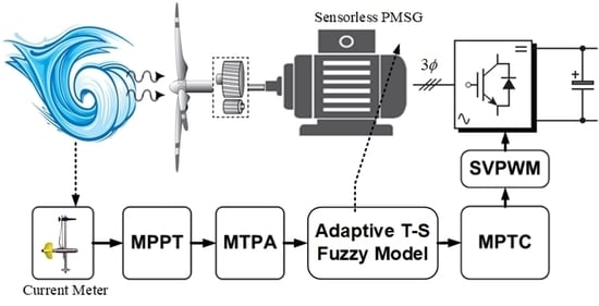
3. Adaptive Takagi–Sugeno Fuzzy Model Predictive Controller Design

In this paper, a novel control architecture for a six-phase PMSG-based hydrokinetic turbine systems (PMSG-HTs) is proposed with the aim of maintaining the maximum hydrokinetic energy extraction under the uncertainty of tidal flow, further improving the control performance and achieving MPPT. Figure 3 presents the block diagram of the proposed adaptive T–S fuzzy model predictive control (ATSFMPC) architecture for PMSG-HTs. As the figure shows, the proposed control architecture has three parts: stator flux reference value estimation, an adaptive T–S fuzzy model (ATSFM), and MPTC.
Notation 2: to implement the following MPTC strategy, the discrete–time domain is used.

3.1. Stator Flux Reference Value Estimation

To achieve the follow-up MPTC under MTPA operation, the appropriate stator flux reference value at the maximum power point of the hydrokinetic power generation system must be computed from the relevant torque reference. In the MTPA strategy, a proportional-integral (PI) controller is first used to calculate the torque reference T e r e f [14,35], which is
T e r e f ( k ) = ( K P + K I s ) Δ ω m ( k )
where Δ ω m ( k ) = ω m r e f ( k ) ω m ( k ) is the rotor speed error. It should be noted that the PI controller parameters were chosen based on a trial and error method to ensure good control performance. Next, the d-q axis stator reference currents were determined using the MTPA operation, which can be defined as follows [31,36]:
i q r e f ( k ) = T e r e f ( k ) 1.5 P [ ψ r + ( L d L q ) i d r e f ( k ) ] , i d r e f ( k ) = ψ r 2 ( L d L q ) ψ r 2 4 ( L d L q ) 2 + ( i q r e f ( k ) ) 2
Based on the two-axis stator reference currents, the stator flux reference can be determined as
ψ s r e f ( k ) = ( ψ r + L d i d r e f ( k ) ) 2 + ( L q i q r e f ( k ) ) 2

3.2. Adaptive Takagi–Sugeno Fuzzy Model

In this study, an adaptive T–S fuzzy model is utilized to represent the nonlinear PMSG-HTs. Besides the model approximation effect, the T–S fuzzy model can also linearize the nonlinear PMSM system. Therefore, the future states of the system can be predicted, i.e., the stator flux and the electromagnetic torque. Here, the T–S fuzzy rules are defined as
R i :   IF   s 1 ( k )   is   M 1 i ,   AND , ,   AND   s n ( k )   is   M n i   THEN   x ^ i ( k ) = F i ( x ( k 1 ) ,   u ( k 1 ) )
where R i ( i = 1 , , l ) represents the i t h fuzzy rule, l refers to the number of rules, s 1 ( k ) , , s n ( k ) are the input variables of the T–S fuzzy model, M j i ( j = 1 , , n ) are the input fuzzy sets, F i ( ) is an arbitrary function, and x ^ i ( k ) is the output in the THEN statement of R i . According to Equation (5), Equation (6), and Remark 3, the input of the T–S fuzzy model can be defined according to the preceding PMSG states x ( k 1 ) = [ i d ( k 1 ) i q ( k 1 ) ω e ( k 1 )   ] T and the controllers u ( k 1 ) = [ u d ( k 1 ) u q ( k 1 ) T m ( k 1 ) ] T , where i d ( k 1 ) ,   i q ( k 1 ) ,   ω e ( k 1 ) denote the d-axis and q-axis currents and the electrical generator rotation speed, respectively. Thus, the aggregated output of the T–S fuzzy model is
x ^ ( k ) = i = 1 l ε i ( k ) δ i T X e ( k ) = Θ ( k ) T κ ( k )
where
ε i ( k ) = j = 1 n M j i ( s j ) / i = 1 l j = 1 n M j i ( s j )
and X e ( k ) = [ x ( k 1 ) ,   u ( k 1 ) ] T , δ i T ( k ) = [ [ a m n ] 3 × 3 , [ b m n ] 3 × 3 ] T with m ,   n = 1 , 2 , 3 , Θ ( k ) = [ δ 1 T ( k ) , , δ l T ( k ) ] T , and κ ( k ) = [ ε 1 ( k ) X e T ( k ) , , ε l ( k ) X e T ( k ) ] T .
To obtain the predictive states of the PMSG, it was important to compute the discrete-time model. Therefore, x ^ ( k ) could be rewritten as
x ^ ( k ) = A ^ x ( k 1 ) + B ^ u ( k 1 )
where A ^ = [ A m n ] 3 × 3 , A m n = i = 1 l ε i ( k ) a m n i ( k ) , B ^ = [ B m n ] 3 × 3 T , B m = i = 1 l ε i ( k ) b m n i ( k ) .
Since the T–S fuzzy model is an adaptive fuzzy system, to establish the adaptive laws via tuning weights, the formulation of the cost function was defined as
E T S ( k ) = 1 2 e T S ( k ) T P e T S ( k )
where e T S ( k ) = x ( k ) x ^ ( k ) is the estimated error and P is the weight matrix. Consequently, by using the gradient descent algorithm, the weights could be adjusted, such that the cost function in Equation (14) was minimized. Thus, the tuning weights formula can be expressed as
Θ ( k + 1 ) = Θ ( k ) + γ ( E T S ( k ) / Θ ( k ) )
where γ is the learning rate and Θ ( k ) is the weighting matrix of the T–S fuzzy model. Thus, the future states of the PMSG could be obtained via the T–S fuzzy model.

3.3. Model Predictive Torque Control

This section focuses on developing the main control task in the MPTC scheme for sensorless PMSG-HTs. First, the torque reference and stator flux reference values based on the MPPT and MTPA schemes were estimated from Equation (8) and Equation (10), respectively. In addition, the d–axis and q–axis currents and the electrical generator rotation speed of the sensorless PMSG were used to obtain the predicted state sequence of its predecessor based on our T–S fuzzy model. Thus, the main characteristics of the MPTC scheme include using an adequate voltage vector selection strategy to indirectly control the stator flux and the electromagnetic torque simultaneously.
Based on the discrete-time T–S fuzzy model of the PMSG as defined in Equation (13), the predictive states can be described as
X ^ ( k + 1 ) = F ^ x ( k ) + G ^ U ( k )
and
F ^ = [ A ^ A ^ 2 A ^ N p ] ;   G ^ = [ B ^ 0 0 A ^ B ^ B ^ 0 A ^ N p 1 B ^ A ^ N p 2 B ^ A ^ N p N c 1 B ^ ]
where X ^ ( k + 1 ) = [ x ( k + 1 ) , , x ( k + N p ) ] T and U ( k ) = [ u ( k ) , , u ( k + N c 1 ) ] T denote the predicted state vector and the control vector, respectively, while N p , N c are the output and control horizon at each time step k . Next, on the basis of the PMSM model, defined in Equation (4), the stator flux in the d–q reference frame within the k th sampling period could be obtained. Here, the prediction of the stator flux at the ( k + 1 ) t h sampling period via the root mean square (RMS) was derived as
ψ s ( k + 1 ) = [ ψ d ( k + 1 ) ] 2 + [ ψ q ( k + 1 ) ] 2
while the prediction of the electromagnetic torque at the ( k + 1 ) t h sampling period could be expressed as
T e ( k + 1 ) = 1.5 P [ ψ d ( k + 1 ) i ^ q ( k + 1 ) ψ q ( k + 1 ) i ^ d ( k + 1 ) ]
where i ^ q and i ^ d are the generator current vector in the d–q axis of our ATSFM scheme.
Remark 4.
the T–S fuzzy model of the PMSG defined in Equation (13) was used to obtain a prediction of the stator current at the next sampling instant from Equation (16). After obtaining i ^ d q ( k + 1 ) , both the torque and the flux at the ( k + 1 ) t h instant could then be obtained according to Equations (4), (17), and (18).
In this paper, pulse-width-modulation (PWM) voltage source converters with two levels (2L–VSCs) were applied to control each set of the three–phase windings of the generator. Each converter comprised of three legs, with the two switches in each leg operating in a complementary mode. Each of the two power switches were controlled via inverse logical signals, with “1” and “0” expressing the “on” and “off” states of the switch, respectively. In general, the cost function for PMSG drives is selected such that both the torque and the flux at the end of the cycle are as close as possible to the required value. Hence, the proposed finite time optimal control problem can be expressed as
min J = ( T e r e f ( k + 1 ) T e ( k + 1 ) ) 2 + λ ψ ( ψ s r e f ( k + 1 ) ψ s ( k + 1 ) ) 2 s . t . U S ( k ) { V 1 , V 2 , , V 6 }
where λ ψ represents the weighting factor (here, the value was set to be λ T = T ¯ e / ψ ¯ s , where T ¯ e and ψ ¯ s are the rated value of torque and stator flux, respectively), U S ( k ) represents the switching state of phase S at the present cycle (where S is the switching vector, i.e., S = [ S a S b S c ] ), and V i is the inverter voltage of the PMSG system. The system also involved six different voltage vectors. All of the possible vectors from V 1 to V 6 for U S ( k ) at the current sampling instant could be easily evaluated such that Equation (19) was minimized. Finally, using the grid-side inverter to control the DC–link voltage v d c ensures that the maximum power will be produced.
For clarity, the flowchart of the proposed ATSFMPC control scheme is shown in Figure 4.
First, to obtain the optimal reference torque and stator flux of PMSG driver at maximum available power of hydropower system, a tidal current meter is used to measure the tidal current speed, and then the maximum power point tracking (MPPT) is employed to estimate the mechanical reference rotation speed ω m r e f when the hydrokinetic turbine runs at the optimal blade tip speed ratio, i.e., perform on the maximum power operating point. According to Remark 3 and PI controller, the reference torque T e r e f can be derived. Using the MTPA approach, the reference stator flux ψ s r e f of the PMSG can further be extracted. Thus, the above reference torque and stator flux of PMSG driver will be as the tracking target for the proposed ATSFMPC strategy. Next, an adaptive Takagi–Sugeno (T–S) fuzzy model is used to express the highly nonlinear behavior of the larger, nonlinear sensorless PMSG-based hydro turbine system using input/output data of sensorless PMSG-based hydro turbine. Based on the T–S fuzzy model, the predicted state sequence of PMSG can then be obtained. Finally, the cost function for PMSG drives is selected, such that both the torque and the flux at the end of the cycle are as close as possible to the reference value. By minimizing the cost, the adequate voltage vector in the voltage–source inverter can then be determined in order to ensure the maximum power will be produced.

4. Simulation Results and Discussion

To verify the performance of the proposed control scheme for PMSG–based hydrokinetic turbine systems (PMSG-HTs), two real-world tidal current profile cases were considered in terms of the northwest European shelf [37] and the Pentland Firth [38]. In addition, considering the future practicability of the hydropower system, the classical PI current control scheme [13,14,15] is, therefore, utilized to compare with the proposed ATSFMPC approach for two realistic tidal current profiles in this paper. Taking a PMSG-HTs as an example, the detailed parameters are provided in Table 1.

4.1. Case 1. Northwest European Shelf Tidal Current Speed Profile

First, a realistic tidal current profile over the northwest European shelf area [37] was considered to demonstrate the effectiveness of the proposed control strategy, wherein the tidal speed profile can be expressed as follows:
v w = { 6 sin ( π 30 t ) ,   t < t 1 r   and   t > t 2 r 4 sin ( π 30 t ) ,   t 1 r < t < t 2 r
where t 1 r and t 2 r represent the initial time and the terminal time, respectively. The northwest European shelf tidal current speed profile is illustrated in Figure 5a. In addition, to maintain the maximum output power of the PMSG-HTs, the MPPT strategy was utilized to derive the mechanical reference rotation speed ω m r e f , as shown in Figure 5b.
Figure 6 shows the simulation results of the d–axis and q–axis rotor currents for the proposed controller and the PI controller. Here, it is clear that the ATSFMPC strategy retained a more stable rotor current without the effect of the disturbance from the regular tidal currents.
Meanwhile, Figure 7 illustrates the performance comparison of the proposed ATSFMPC strategy and the conventional PI controller. To extract the maximum hydropower, the power coefficient should be maintained at its maximum value. Figure 7a shows that the maximum power coefficient C p max was largely achieved by the proposed controller despite the regular tidal current. Figure 7b shows that simulation compared the DC–link output voltage for the conventional PI controller and the proposed ATSFMPC scheme at the 200 V operation mode. As can be observed, voltage fluctuation of the proposed ATSFMPC scheme was smaller than PI controller when there were random fluctuations due to the uncertainty of tidal current speed, meaning the proposed ATSFMPC scheme can contribute to maintaining a more stable DC-link output voltage of the grid to increase the electric quality. Figure 7c,d shows the output voltages in terms of the d–q axis and the turbine power, respectively. Here, it is clear that the proposed ATSFMPC scheme provided a more stable stator voltage than the PI control method. Meanwhile, Figure 8d shows the hydrokinetic turbine power generated online from the variation current and voltage. Furthermore, obviously, as seen in Figure 5 and Figure 6, the proposed ATSFMPC scheme has faster response and good performance when tidal current speed is changed instantly (sixth cycle) because its prediction optimal output derives future possible control input via evaluation of future resulting states. Conversely, the results indicate that the proposed ATSFMPC strategy demonstrated a superior performance and provided a more stable output to the grid. Moreover, Table 2 shows that the proposed ATSFMPC scheme can achieve closer to the 200 V operation mode for Northwest European shelf, and it has a smaller rms relative error of DC–link voltage values, and, further, it will effectively enable more efficient and stable hydrokinetic energy production.

4.2. Case 2. Pentland Firth Tidal Current Speed Profile

In this case, the following realistic Pentland Firth tidal current speed profile [38] is defined as:
v w = { 8 sin ( π 30 t ) ,   t < t 1 r   7 sin ( π 30 t ) ,   t 1 r < t < t 2 r 6 sin ( π 30 t ) ,   t 3 r < t < t 4 r 2 sin ( π 30 t ) ,   t > t 4 r
where t 1 r ,   t 2 r ,   t 3 r , and t 4 r represent the initial, interval, and terminal times, respectively. The Pentland Firth tidal current speed profile is illustrated in Figure 8a. The mechanical reference rotation speed ω m r e f was obtained via the MPPT strategy, as shown in Figure 8b.
Figure 9 shows the response comparison between the proposed ATSFMPC strategy and the conventional PI controller. As the figure shows, the generated d-axis and q-axis currents for the hydro turbine continuously followed the tidal current speed pattern. In addition, the proposed ATSFMPC strategy largely provided a more stable output than the PI control method, while the maximum torque/ampere was achieved via the MTPA operation and the q-axis directly tracked the reference electromagnetic torque. Meanwhile, Figure 10 shows the simulation comparison of the proposed ATSFMPC strategy and the conventional PI controller. As shown in Figure 10a,b, the power coefficient and the DC-link voltage in the proposed control scheme exhibited less oscillations than in the conventional method. This means that the proposed control scheme provided a more efficient power generation, which was also maintained at maximum power.
Moreover, Figure 10c,d shows the d–q axis output voltages and the turbine power, respectively. The results indicate that the proposed strategy demonstrated a superior performance and provided a more stable output to the grid. Finally, Table 3 shows that the proposed ATSFMPC scheme can achieve closer to the 200 V operation mode for two Pentland Firth tidal currents, and it has a smaller relative RMS-error of DC-link voltage values, and, further, it will effectively enable a more efficient and stable hydrokinetic energy production. In other words, the proposed ATSFMPC approach can be applied to effectively suppress random fluctuations of the tidal current for supplying the stable electrical power with the hydro turbine at all times.

5. Conclusions

In this paper, an adaptive T–S fuzzy model predictive control (ATSFMPC) strategy has been proposed for a sensorless PMSG-based hydrokinetic turbine systems (PMSG-HTs) when there are random fluctuations due to the uncertainty of tidal current speed. To estimate the optimal reference torque and stator flux of the PMSG driver, an ocean current meter is first employed to measure the tidal current speed, and then the maximum power point tracking (MPPT) scheme is applied to predict and track the maximum power point in order to maximize the output power. Meanwhile, the maximum torque per ampere (MTPA) approach is used to derive the optimal reference torque and stator flux as a tracking target for the following proposed ATSFMPC strategy. Moreover, an adaptive T–S fuzzy model is implemented to deal with the nonlinearity of a PMSG-HTs. Thus, the nonlinear system can be represented by several linear sub–systems. Based on the T–S fuzzy model, the model predictive torque control (MPTC) strategy is then utilized to indirectly control the electromagnetic torque and stator flux by selecting an adequate voltage vector selection strategy, which not only improves the control performance, but also achieves maximum hydro power tracking. Eventually, two real-world tidal current speed profiles are utilized to verify the performance of the proposed control scheme and compared with the classical proportional-integral (PI) control strategy. According to the numerical simulation results, the proposed ATSFMPC scheme represents an improved performance, compared with the PI controller. The ATSFMPC strategy fully meets the desired objectives of ensuring stable tidal current conversion efficiency and output power of hydrokinetic turbine. We believe that our approach not only can establish technology in developing hydrokinetic power generation for Taiwan, but also holds great promise for solving a variety of practical engineering problems and challenges.

Author Contributions

Conceptualization, Y.-C.L. and V.E.B.; methodology, Y.-C.L. and Y.-H.C.; software, Y.-H.C. and J.-H.Y.; validation, Y.-H.C.; formal analysis, Y.-C.L.; investigation, Y.-H.C.; data curation, Y.-C.L. and V.E.B.; writing—original draft preparation, Y.-C.L. and Y.-H.C.; writing—review and editing, Y.-C.L. and V.E.B.; visualization, J.-F.Y.; supervision, V.E.B. All authors have read and agreed to the published version of the manuscript.

Funding

This research received no external funding.

Conflicts of Interest

The authors declare no conflict of interest.

Nomenclature

SymbolDefinition
P w Hydrokinetic power (W)
ρ Ocean density ( kg / m 3 )
A T Cross sectional area of the turbine through water flows ( m 2 )
r T Blade radius ( m )
v w Tidal current speed ( m / s )
C p ( λ , β ) Power coefficient
λ Tip speed ratio
β Pitch angle of the turbine (deg)
ω m Generator mechanical rotation speed ( rad / s )
ω e Electrical generator rotation speed ( rad / s )
ω m r e f Mechanical reference rotation speed ( rad / s )
λ o p t Optimal blade tip speed ratio
C p max Maximum power coefficient
u d , u q d-axis and q-axis voltages (V)
i d , i q d-axis and q-axis currents (A)
i d r e f , i q r e f d-axis and q-axis reference currents by MTPA (A)
ψ d , ψ q d-axis and q-axis stator flux linkages ( Wb - t )
ψ s r e f Stator reference flux linkage ( Wb - t )
L d , L q d-axis and q-axis stator inductances (H)
J r Overall rotor inertia ( kg m 2 )
B m Viscous friction coefficient
T m Mechanical torque ( N m )
T e Electromagnetic torque ( N m )
K P ,   K I PI control gains
A ^ ,   B ^ T–S fuzzy model
e T S Estimated error of adaptive T–S fuzzy model
U S Switching state of phase
S Switching vector
V i ,   i = 1 , , 6 Inverter voltage vectors
P Number of pole pairs

References

  1. Sönnichsen, N. Global Outlook on Electricity Generation by Energy Source 2018–2050. In Statista—The Statistics Portal; UNH Library: Durham, NH, USA, 2020. [Google Scholar]
  2. International Renewable Energy Agency (IRENA). Renewable Capacity Highlights. In IRENA’s Renewable Energy Statistics; IRENA: Abu Dhabi, UAE, 2020; ISBN 978-92-9260-246-8. [Google Scholar]
  3. Boretti, A. State-of-the-Art of MW-Level Capacity Oceanic Current Turbines. In Nonlinear Engineering; De Gruyter: Berlin, Germany, 2020; Volume 9, pp. 361–369. [Google Scholar]
  4. Ministry of Economic Affairs (MOEA). Renewable Energy Development Act. Available online: https://law.moj.gov.tw/ENG/LawClass/LawAll.aspx?pcode=J0130032 (accessed on 25 September 2020).
  5. Taiwan Power Company. Sustainable Power, Caring Forever. In Taiwan Power Company Sustainability Report; Taiwan Power Company: Taipei, Taiwan, 2018. [Google Scholar]
  6. Hsing, H.C.; Lee, H.I. Comprehensive Overview of Renewable Energy Development in Taiwan. Renew. Sustain. Energy Rev. 2014, 37, 215–228. [Google Scholar]
  7. Wong, S. Annual Electricity Generation from Pumped Storage and Conventional Hydropower in Taiwan from 2008 to 2018. In Statista—The Statistics Portal; UNH Library: Durham, NH, USA, 2020. [Google Scholar]
  8. Guner, F.; Zenk, H. Experimental, Numerical and Application Analysis of Hydrokinetic Turbine Performance with Fixed Rotating Blades. Energies 2020, 13, 766. [Google Scholar] [CrossRef] [Green Version]
  9. Rajabpour, L.; Shasadeghi, M.; Barzegar, A. Design of Robust H∞ Fuzzy Output Feedback Controller for Affine Nonlinear Systems: Fuzzy Lyapunov Function Approach. Int. J. Adv. Intell. Parad. 2019, 14, 328–344. [Google Scholar]
  10. Casadei, D.; Profumo, F.; Serra, G.; Tani, A. FOC and DTC: Two Viable Schemes for Induction Motors Torque Control. IEEE Trans. Power Electron. 2002, 17, 779–787. [Google Scholar] [CrossRef] [Green Version]
  11. Nasr, A.; Gu, C.; Bozhko, S.; Gerada, C. Performance Enhancement of Direct Torque-Controlled Permanent Magnet Synchronous Motor with a Flexible Switching Table. Energies 2020, 13, 1907. [Google Scholar] [CrossRef] [Green Version]
  12. Morales-Caporal, R.; Bonilla-Huerta, M.E.; Arjona, A.; Hernandez, C. Sensorless Predictive DTC of a Surface-Mounted Permanent-Magnet Synchronous Machine Based on Its Magnetic Anisotropy. IEEE Trans. Ind. Electron. 2013, 60, 3016–3024. [Google Scholar] [CrossRef]
  13. Yang, S.; Zhang, L. Modeling and Control of the PMSG Wind Generation System with A Novel Controller. In Proceedings of the 3th IEEE International Conference on Intelligent System Design and Engineering Applications, Hong Kong, China, 16–18 January 2013; pp. 946–949. [Google Scholar]
  14. Kim, Y.S.; Chung, I.Y.; Moon, S.I. Tuning of the PI Controller Parameters of a PMSG Wind Turbine to Improve Control Performance under Various Wind Speeds. Energies 2015, 8, 1406–1425. [Google Scholar] [CrossRef] [Green Version]
  15. Errouissi, R.; AI-Durra, A.; Debouza, M. A Novel Design of PI Current Controller for PMSG-Based Wind Turbine Considering Transient Performance Specifications and Control Saturation. IEEE Trans. Ind. Electron. 2018, 65, 8624–8634. [Google Scholar] [CrossRef]
  16. Yang, B.; Yu, T.; Shu, H.; Han, Y.; Cao, P.; Jiang, L. Adaptive Fractional-Order PID Control of PMSG-Based Wind Energy Conversion System for MPPT Using Linear Observers. Int. Trans. Electr. Energy Syst. 2019, 29, 1–18. [Google Scholar] [CrossRef] [Green Version]
  17. Benelghali, S. Experimental Validation of a Marine Current Turbine Simulator: Application to a Permanent Magnet Synchronous Generator-Based System Second-Order Sliding Mode Control. IEEE Trans. Ind. Electr. 2011, 58, 118–126. [Google Scholar] [CrossRef] [Green Version]
  18. Pourebrahim, R.; Tohidi, S.; Younesi, A. Sensorless Model Reference Adaptive Control of DFIG by Using High Frequency Signal Injection and Fuzzy Logic Control. Iran. J. Electr. Electr. Eng. 2018, 14, 11–21. [Google Scholar]
  19. Pathak, K.B.; Adhyaru, D.M. Performance Analysis of Lyapunov Stability-Based and ANFIS-Based MRAC. Int. J. Comput. Syst. Eng. 2019, 5, 119–127. [Google Scholar] [CrossRef]
  20. M’zoughi, F.; Garrido, I.; Garrido, A.J.; De La Sen, M. Self-Adaptive Global-Best Harmony Search Algorithm-Based Airflow Control of a Wells-Turbine-Based Oscillating-Water Column. Appl. Sci. 2020, 10, 4628. [Google Scholar] [CrossRef]
  21. Song, S.K.; Park, J.B. Control Strategy of an Impulse Turbine for an Oscillating Water Column-Wave Energy Converter in Time-Domain Using Lyapunov Stability Method. Appl. Sci. 2016, 6, 281. [Google Scholar] [CrossRef] [Green Version]
  22. Geyer, T.; Papafotiou, G.; Morari, M. Model Predictive Direct Torque Control-Part I: Concept, Algorithm, and Analysis. IEEE Trans. Ind. Electr. 2009, 56, 1894–1905. [Google Scholar] [CrossRef]
  23. Singh, M.; Chandra, A. Application of Adaptive Network-Based Fuzzy Inference System for Sensorless Control of PMSG-Based Wind Turbine with Nonlinear-Load-Compensation Capabilities. IEEE Trans. Power Electr. 2011, 26, 165–175. [Google Scholar] [CrossRef]
  24. Yin, X.; Zhang, W.; Jiang, Z.; Pan, L.; Lei, M. Adaptive Backstepping Control for Maximizing Marine Current Power Generation Based on Uncertainty and Disturbance Estimation. Electr. Power Energy Syst. 2020, 117, 1–11. [Google Scholar] [CrossRef]
  25. Hussain, S.; Bazaz, M.A. Modified SVPWM Technique for a Sensorless Controlled Induction Motor Drive Using Neural Network Observer and Predictive Controller. Int. J. Adv. Intell. Parad. 2020, 16, 172–189. [Google Scholar] [CrossRef]
  26. Boldea, I. The Electric Generators Handbook: Synchronous Generators; Taylor & Francis Group, LLC: Boca Raton, FL, USA, 2006. [Google Scholar]
  27. Abdelrahem, M.; Hackl, C.M.; Kennel, R. Implementation and Experimental Investigation of a Sensorless Field-Oriented Control Scheme for Permanent-Magnet Synchronous Generato. Electr. Eng. 2018, 100, 849–856. [Google Scholar] [CrossRef]
  28. Shahriari, S.A.A.; Raoofat, M.; Dehghani, M.; Mohammadi, M.; Saad, M. Dynamic State Estimation of a Permanent Magnet Synchronous Generator-Based Wind Turbine. IET Renew. Power Gener. 2016, 10, 1278–1286. [Google Scholar] [CrossRef]
  29. Urbanski, K.; Janiszewski, D. Sensorless Control of the Permanent Magnet Synchronous Motor. Sensors 2019, 19, 3546. [Google Scholar] [CrossRef] [PubMed] [Green Version]
  30. Koutroulis, E.; Kalaitzakis, K. Design of a Maximum Power Tracking System for Wind-Energy-Conversion Applications. IEEE Trans. Ind. Electr. 2006, 53, 486–494. [Google Scholar] [CrossRef]
  31. Preindl, M.; Bolognani, S. Model Predictive Direct Torque Control with Finite Control Set for PMSM Drive Systems, Part 1: Maximum Torque per Ampere Operation. IEEE Trans. Ind. Inf. 2013, 9, 1912–1921. [Google Scholar] [CrossRef]
  32. Chica, E.; Clemente, A.R. Design of Zero Head Turbines for Power Generation. In Renewable Hydropower Technologies; IntechOpen: London, UK, 2017; pp. 25–52. [Google Scholar] [CrossRef] [Green Version]
  33. Elzalabani, M.M.; Fahmy, F.H.; Nafeh, A.E.A.; Allam, G. Modelling and Simulation of Tidal Current Turbine with Permanent Magnet Synchronous Generator. Indones. J. Electr. Eng. 2015, 13, 57–64. [Google Scholar] [CrossRef]
  34. Chica, E.; Perez, F.; Clemente, A.R.; Agudelo, S. Design of a Hydrokinetic Turbine. WIT Trans. Ecol. Environ. 2015, 195, 137–148. [Google Scholar]
  35. Kumar, R.; Das, S. Model Reference Adaptive System-Based Sensorless Speed Control of Grid-Connected Doubly Fed Induction Generator in Wind Energy Conversion System. Iran. J. Sci. Technol. Trans. Electr. Eng. 2020, 44, 129–140. [Google Scholar] [CrossRef]
  36. Yaramasu, V.; Wu, B. Model Predictive Control of Wind Energy Conversion Systems; John Wiley & Sons, Inc.: Hoboken, NJ, USA, 2017. [Google Scholar]
  37. Robins, P.E.; Neill, S.P.; Lewis, M.J.; Ward, S.L. Characterising the Spatial and Temporal Variability of the Tidal-Stream Energy Resource Over the Nourthwest European Shelf Seas. Appl. Energy 2015, 147, 510–552. [Google Scholar] [CrossRef] [Green Version]
  38. Molen, J.V.D.; Ruardij, P.; Greenwood, N. Potential Environmental Impact of Tidal Energy Extraction in the Pentland Firth at Latge Spatial Scales: Results of a Biogeochemical Model. Biogeosciences 2016, 13, 2593–2609. [Google Scholar]
Figure 1. Block diagram of tidal energy conversion system.
Energies 13 05296 g001
Figure 2. (a) Relationship between tip speed ratio and power coefficient; (b) hydrokinetic turbine power for different maximum amplitude of tidal current speed.
Energies 13 05296 g002
Figure 3. Block diagram of the proposed adaptive T–S fuzzy model predictive control (ATSFMPC) architecture.
Energies 13 05296 g003
Figure 4. Flowchart of the proposed ATSFMPC control scheme.
Energies 13 05296 g004
Figure 5. Input and reference signals. (a) Northwest European Shelf tidal current speed profile; (b) mechanical reference rotation speed by maximum power point tracking (MPPT).
Energies 13 05296 g005
Figure 6. Response of d-axis and q-axis rotor currents for proportional-integral (PI) and ATSFMPC for Northwest European shelf.
Energies 13 05296 g006
Figure 7. Simulation results of the conventional PI controller and the proposed ATSFMPC scheme in Northwest European shelf. (a) Power coefficient response; (b) DC-link output voltage; (c) d-q axis output voltage; (d) turbine power in ATSFMPC method.
Energies 13 05296 g007
Figure 8. Input and reference signals. (a) Pentland Firth tidal current speed profile; (b) mechanical reference rotation speed by MPPT.
Energies 13 05296 g008
Figure 9. Response of d-axis and q-axis rotor currents for PI and ATSFMPC for Pentland Firth tidal current.
Energies 13 05296 g009
Figure 10. Simulation results of the conventional PI controller and the proposed ATSFMPC scheme in Pentland Firth tidal current. (a) Power coefficient response; (b) DC–link output voltage; (c) d–q axis output voltage; (d) turbine power in ATSFMPC method.
Energies 13 05296 g010
Table 1. Parameter Values of the PMSG–HTs.
SymbolQuantityValue
R s Phase resistance 1 Ω
L d , L q Stator d-axis and q-axis inductances 0.025 H
P Number of pole pairs 4
ψ r Magnet flux linkage 0.272   Wb
V d c DC bus voltage200 V
J r Moment of overall inertia 8 × 10 4 kgm2
B m Viscous friction coefficient 10 3 N m/s
r T The distance of blade radius 3 m
ρ The density of ocean 1028 kg/m3
A T Rotor blade area 28.26 m2
Table 2. Comparison of DC-link voltage regulation performances for Northwest European shelf.
ItemATSFMPCPI
Average DC-Link Voltage (V)199.7241199.6719
Relative Error of DC-Link Voltage (RMS)1.01396.4472
Table 3. Comparison of DC-link voltage regulation performances for Pentland Firth tidal current.
ItemATSFMPCPI
Average DC-Link Voltage (V)199.4414199.4224
Relative Error of DC-Link Voltage (RMS)0.91206.0544

