Abstract
An artificial neural network (ANN)-based supplementary frequency controller is designed for a doubly fed induction generator (DFIG) wind farm in a local power system. Since the optimal controller gain that gives highest the frequency nadir or lowest peak frequency is a complicated nonlinear function of load disturbance and system variables, it is not easy to use analytical methods to derive the optimal gain. The optimal gain can be reached through an exhaustive search method. However, the exhaustive search method is not suitable for online applications, since it takes a long time to perform a great number of simulations. In this work, an ANN that uses load disturbance, wind penetration, and wind speed as the inputs and the desired controller gain as the output is proposed. Once trained by a proper set of training patterns, the ANN can be employed to yield the desired gain in a very efficient manner, even when the operating condition is not included in the training set. Therefore, the proposed ANN-based controller can be used for real-time frequency control. Results from MATLAB/SIMULINK simulations performed on a local power system in Taiwan reveal that the proposed ANN can yield a better frequency response than the fixed-gain controller.
1. Introduction
To increase the percentage of green energy, wind farms are being built in Taiwan. It is expected that the installed capacities of these wind farms will reach 4.2 GW by 2025 [1]. For a system with a high penetration of wind power, the frequency regulation of the local power system becomes very important, especially when it is disconnected from the main grid due to a fault, resulting in islanding operation. How to design a proper supplementary frequency controller for the wind farm, such that the frequency for a local power system in the islanding operation can be controlled satisfactorily, is of major concern in this work.
Numerous works have been devoted to the design of a supplementary frequency controller for a doubly fed induction generator (DFIG) in order to improve the system frequency under disturbance conditions [2,3,4,5,6,7,8,9,10,11,12,13,14]. Both a proportional (droop) controller [2,3,4,5,6] and proportional (droop)–derivative (inertial) (PD) controller [7,8,9] have been extensively studied.
In the design of proper gains for the droop controller and inertia controller, the objective is to improve the dynamic system frequency response and keep the DFIG speed within the allowable range after a disturbance. Since the dynamic system frequency response is a complicated nonlinear function of load disturbance and system variables such as wind speed and the percentage of wind power penetration, it is not easy to derive an analytical formula relating the system frequency and DFIG speed to the load disturbance and system variables and get the desired optimal solutions for the droop and inertia gains using analytical methods. In the literature, numerous works have been reported [9,10,11,12,13,14,15,16,17,18,19] to get the desired gains using a simulation-based method. The frequency and speed responses with and without droop control were compared in [9]. The effect of proportional gain on the frequency response was investigated in [15], with the derivative gain being fixed at 15. The influence of governor speed, droop gain, and inertia gain on frequency deviation was examined in [16]. The effect of DFIG penetration on the frequency deviation was also studied [16]. System frequency and maximum transient frequency deviation under different values of droop and inertia gains were investigated in [17]. In [18], the frequency nadir and rate of change of frequency for different wind power penetrations, different percentages of steam turbines, and combined cycle gas turbines were analyzed in order to reach the optimal droop and inertia gain settings. It was found that the optimal inertia gain was near zero for most cases, and the inertia term could be neglected. In [19], the root locus and system frequency response for proportional and inertia control were depicted under different wind speeds. The effect of increased wind penetration on the root locus and frequency response was also studied.
The optimal controller gain that gives the highest frequency nadir for a system under a particular condition of load disturbance, wind speed, and wind penetration can be reached by an exhaustive search method in which the dynamic frequency response curves following a disturbance are simulated for all possible gains, and the gain that gives the highest frequency nadir is selected as the optimal gain. However, the exhaustive search method is not suitable for online applications, since it takes a long time to perform a great number of simulations.
The main purpose of this work is to design an artificial neural network (ANN) [20,21]-based frequency controller that gives the desired droop gain in a very efficient manner. The inputs to the ANN are the load disturbance and system variables, such as the wind speed and percentage of wind power penetration, which have significant impacts on the system frequency response [17,18,19]. Computer simulations are first conducted to obtain the optimal droop gains that give the highest frequency nadir (FN) (in the case of load increase) or lowest peak frequency (in the case of load decrease) for the system under different values of load disturbances, wind power penetrations, and wind speeds. The compiled ANN outputs (optimal droop gains) and the corresponding ANN inputs (load disturbance, wind penetration, and wind speed) are employed as the ANN training patterns. Once the ANN is trained, it can be used to provide the desired droop gain in a very efficient manner without any time-consuming simulations. Therefore, the proposed ANN-based frequency controller can be used for online applications.
The main contributions of the paper are summarized as follows:
- The effects of load disturbance, percentage of wind penetration, and wind speed on the optimal droop gain are investigated.
- The designed ANN-based frequency controller can yield the desired droop gain in a very efficient manner. Thus, it is suitable for real-time applications.
- The proposed ANN-based frequency controller can give a better frequency response than the fixed-gain controller. In addition, the ANN can yield controller gains that are very close to the optimal gains, even when the input variables such as wind speed, wind penetration, and load disturbance are not included in the training patterns of the ANN.
2. System Model
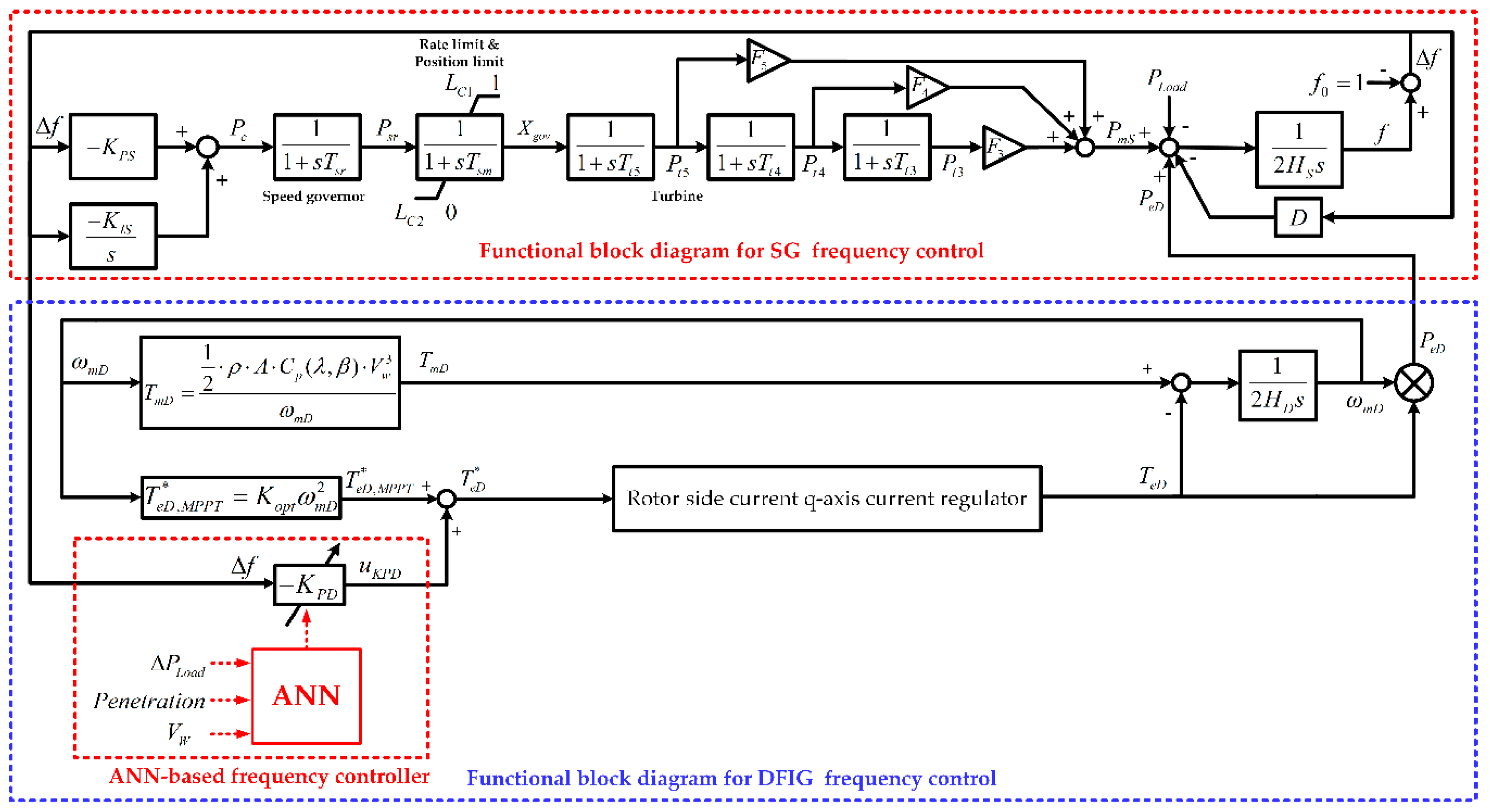
The system under study is a local power system in Taiwan with wind farms that are lumped together as an equivalent DFIG [6]. The six fossil-fired steam turbine generators in the local power system are lumped together as an equivalent synchronous generator (SG). Figure 1 depicts the nonlinear block diagram for the synchronous generator frequency control and DFIG supplementary frequency control. Details on the block diagrams for the governor, turbine, synchronous generator, and DFIG were described in [6].

Figure 1.
Block diagram for a frequency control system. SG: synchronous generator, ANN: artificial neural network, DFIG: doubly fed induction generator.
In this work, an ANN-based controller as shown in Figure 1 is proposed to adapt the gain for the DFIG supplementary frequency controller based on the load disturbance , wind power penetration, and wind speed .
3. Effect of Load Disturbance, Wind Power Penetration, and Wind Speed on the Optimal Controller Gain
As shown in Figure 1, the system frequency f under disturbance conditions for a power system with a DFIG wind farm is governed by the swing equation of the synchronous machine:
where is the mechanical power of the synchronous machine, is the electrical power of the DFIG, is the load demand, and and D are the equivalent per unit inertia constant for all synchronous generators in the power system and the load damping constant, respectively.
It is observed from Equation (1) that the system frequency deviates from its nominal value (1 pu or 60 Hz) when there is a disturbance in the system load. In order to restore the system frequency to its nominal value, the mechanical power of the synchronous generators will be adjusted through the action of speed governors and turbines, and the DFIG electrical power output can also be modulated by the supplementary frequency controller denoted by − in Figure 1.
The main purpose of this work is to design a proper gain to meet the following objective function and constraints: [8,22,23]
Note that only the frequency nadir or peak frequency is considered in the objective function, since the main purpose is to keep the system frequency within the allowable limit to avoid load shedding in an isolated power system. In addition, only the droop control is considered, since it was pointed out in [18] that the inertial constant is near zero and can be omitted.
It is observed from Figure 1 that the DFIG output power can be written as
where and are the electrical torque and speed of the DFIG, respectively.
Note that the mechanical torque is given by
It is concluded from Equations (4) and (5) that the DFIG output power is a function of wind penetration and wind speed . Therefore, the dynamic frequency response following a load disturbance will be affected by the load disturbance , wind penetration, and wind speed , and the optimal controller gain will be function of the three parameters of , wind penetration, and .
In the design of a fixed-gain supplementary frequency controller, the controller gain is usually determined based on a nominal operating condition, e.g., = 30 MW, wind penetration = 29.4%, and = 11 m/s.
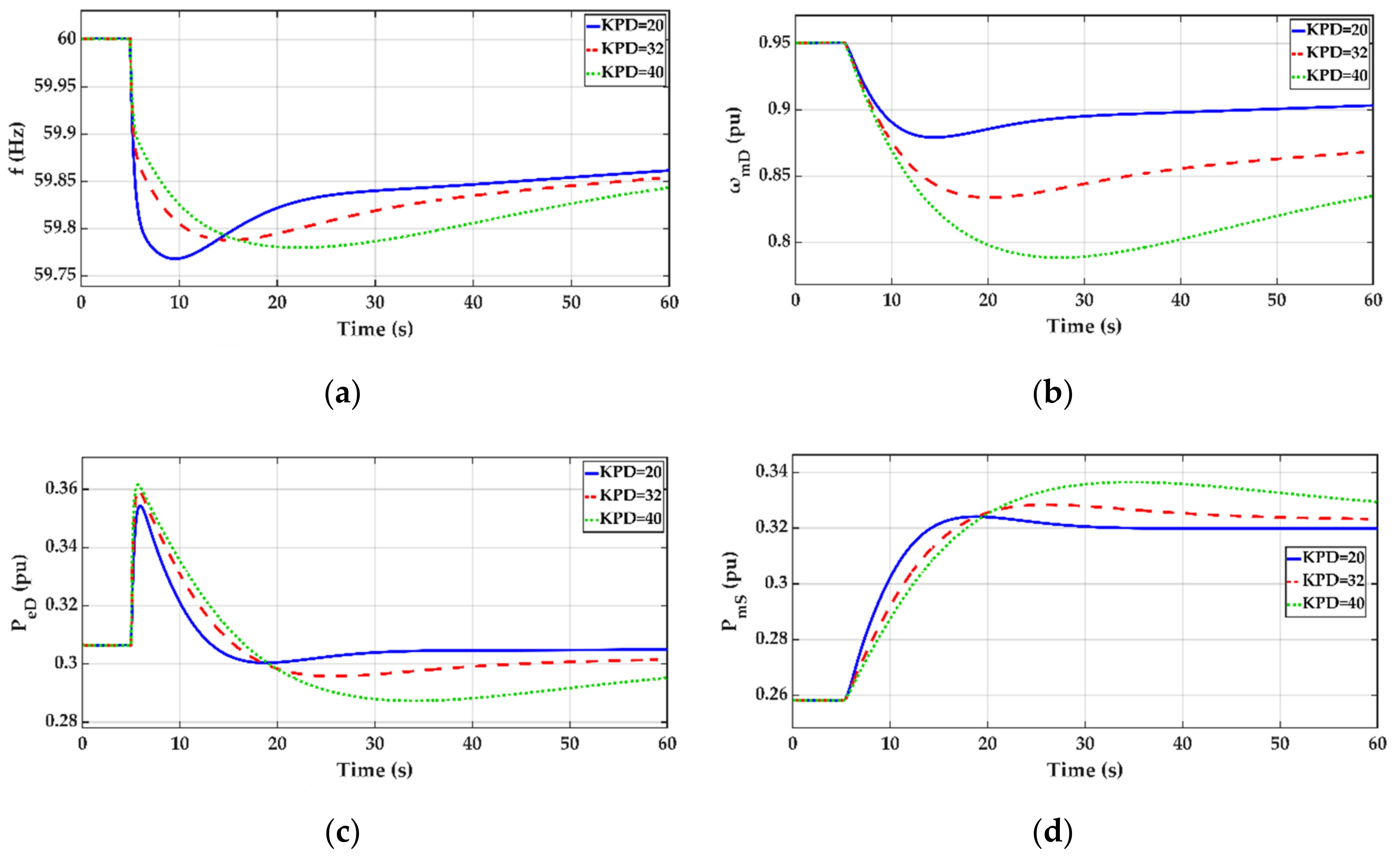
Figure 2 depicts the dynamic response curves for the system subject to a load disturbance of = 30 MW (wind penetration = 29.4% and = 11 m/s). An observation of the frequency response in Figure 2a reveals that the controller gain = 32 gives the highest frequency nadir. Additionally shown in Figure 2a are the frequency response curves for the case with a smaller gain = 20 and for the case with a larger gain = 40. As shown in Figure 2c, the DFIG delivers less electrical power to the system and results in a lower frequency nadir when a smaller gain = 20 is employed. On the other hand, a larger gain of = 40 causes smaller frequency dips in the first few seconds following the disturbance and results in a lesser mechanical power increase for the synchronous generator and lower frequency nadir than the case of = 32. Therefore, an optimal gain of = 32 is selected for the base case of = 30 MW, wind penetration = 29.4%, and = 11 m/s.

Figure 2.
Dynamic response curves for a load disturbance of = 30 MW (wind penetration = 29.4% and = 11 m/s). (a) Frequency, (b) DFIG speed, (c) DFIG electrical power, and (d) SG mechanical power. : the optimal gain.
Since the optimal gain changes with the load disturbance , wind penetration, and wind speed , the effect of these parameters on the optimal gain is examined below.
3.1. Effect of Load Disturbance ΔPLoad on the Optimal Gain KPD
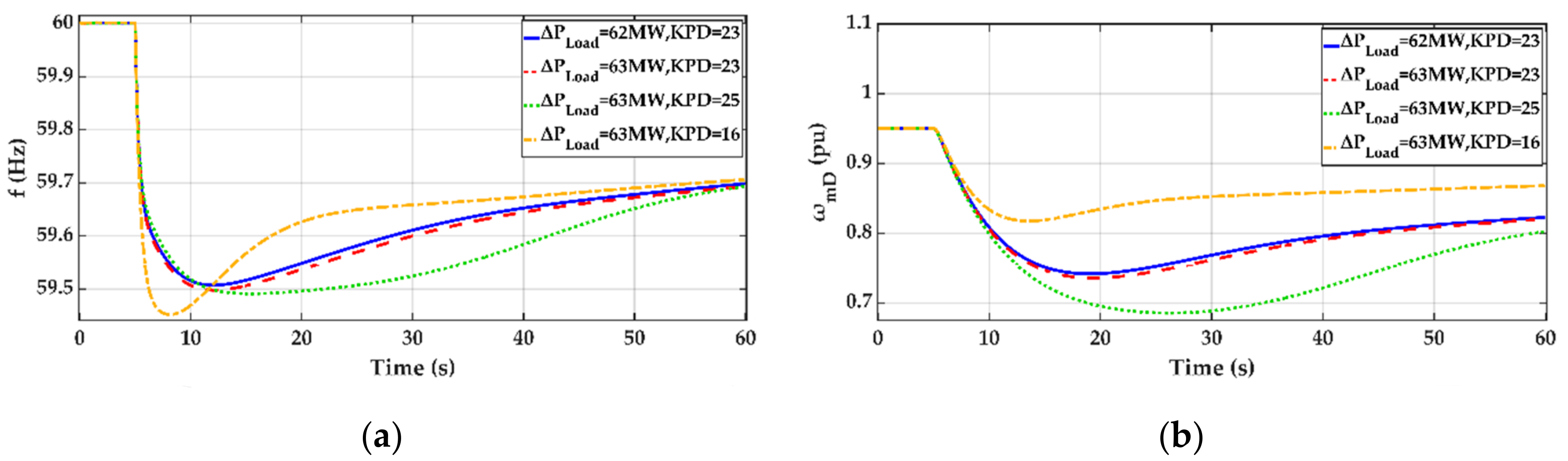
Figure 3 depicts the dynamic response curves for the system subject to load increases of = 62 MW and = 63 MW, respectively.

Figure 3.
Dynamic response curves for the system subject to a load increase of = 62 MW and 63 MW (wind penetration = 29.4% and = 11 m/s). (a) Frequency and (b) DFIG speed.
It is observed from Figure 2 and Figure 3a that the optimal gain decreases from 32 to 23 as the is increased from 30 MW to 62 MW. It is also observed from Figure 2 and Figure 3a that the frequency nadir decreases with the increasing load disturbance. Note that the frequency nadir reaches the lower limit of 59.5 Hz as the load disturbance is increased to 62 MW. If the load disturbance is increased further to 63 MW, the frequency nadir is below 59.5 Hz when the gain remains at 23. When the gain is increased to 25, the DFIG speed drops to a value lower than 0.7, and the frequency nadir is still below 59.5 Hz. If the gain is decreased to 16, the DFIG speed will be higher than 0.7 but the frequency nadir lower than 59.5 Hz.
It is thus concluded from Figure 3 that it is impossible to find a proper gain within the allowable range (16 50) when the load disturbance is 63 MW. Therefore, = 62 MW is the upper limit for the load increase.
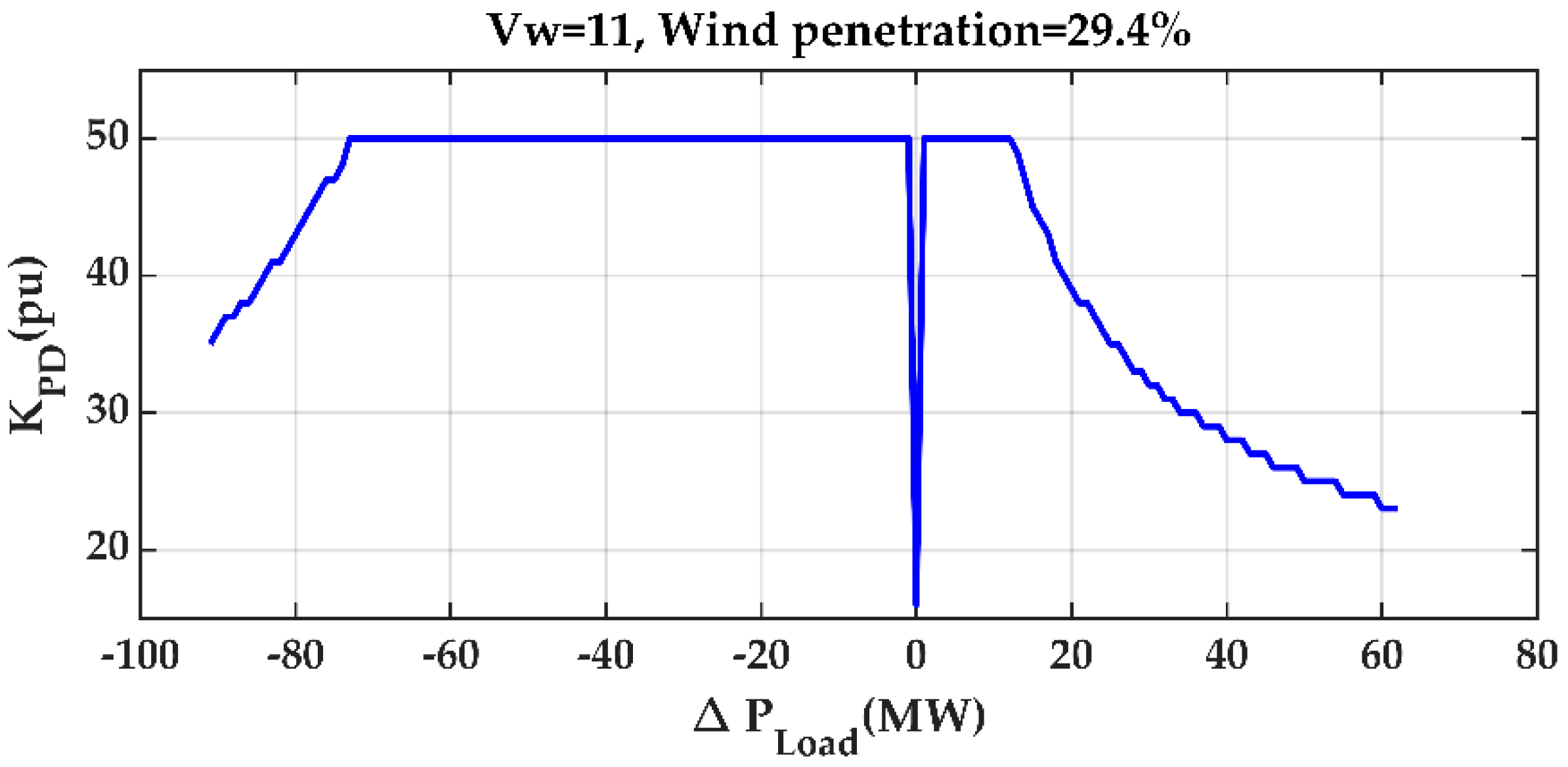
Figure 4 depicts the optimal gain as a function of the load disturbance . It is observed from Figure 4 that the optimal controller gain varies with the magnitude of the load disturbance . This motivates the design of an ANN-based controller such that the controller gain can be adapted with the load disturbance, and the load disturbance must be selected as one of the inputs to the ANN-based controller.

Figure 4.
Optimal gain as a function of the load disturbance (wind penetration = 29.4% and = 11 m/s).
3.2. Effect of the Percentage of Wind Penetration on the Optimal Gain KPD
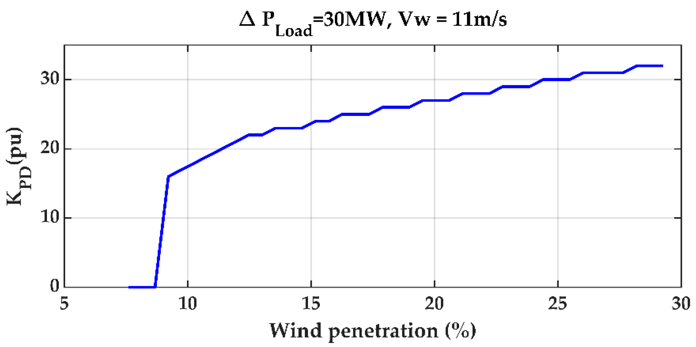
Figure 5 depicts the optimal gain as a function of the percentage of wind penetration ( = 30 MW and = 11 m/s).

Figure 5.
Optimal gain as a function of wind penetration ( = 30 MW and = 11 m/s).
It is observed from Figure 5 that the optimal gain varies from 32 to 28 and 23 as the wind penetration changes from 29.4% to 22.05% and 14.7%, respectively. No feasible solution that satisfies the frequency and DFIG speed constraints can be found as the wind penetration is decreased to 7.35%. It is thus concluded that the wind penetration has a significant impact on the design of the optimal controller gain and must be employed as one of the inputs to the ANN-based controller.
3.3. Effect of the Percentage of Wind Speed on the Optimal Gain KPD
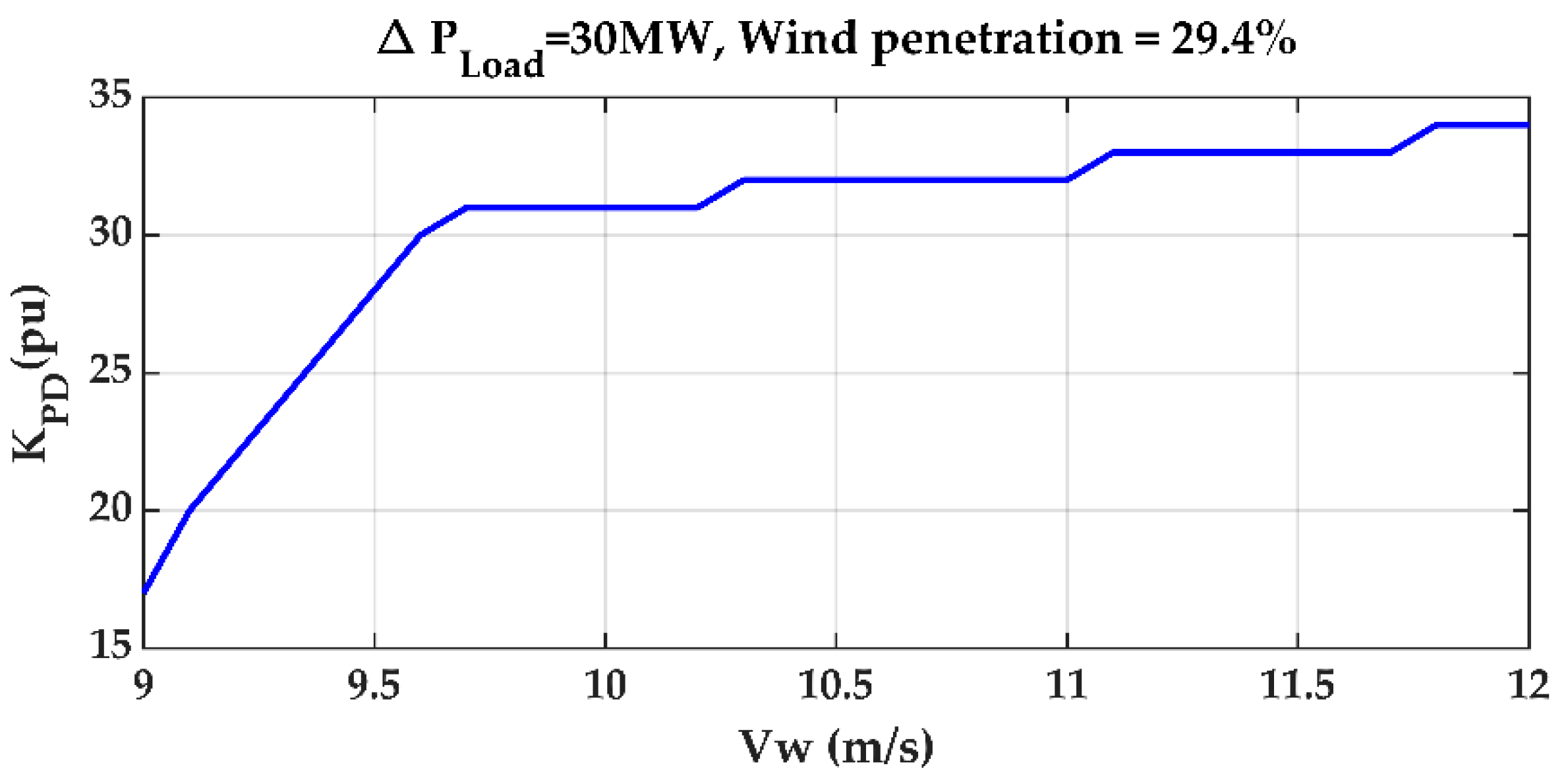
Figure 6 depicts the optimal gain as a function of wind speed ( = 30 MW and wind penetration = 29.4%). It is observed from Figure 6 that the optimal gain varies from 34 to 32, 31, and 17 as the wind speed is decreased from 12 m/s to 11 m/s, 10 m/s, and 9 m/s, respectively. Therefore, the wind speed is selected as one of the inputs to the ANN-based controller, as it has a considerable effect on the optimal controller gain .

Figure 6.
Optimal gain as a function of the wind speed ( = 30 MW and wind penetration = 29.4%).
4. ANN-Based Frequency Controller
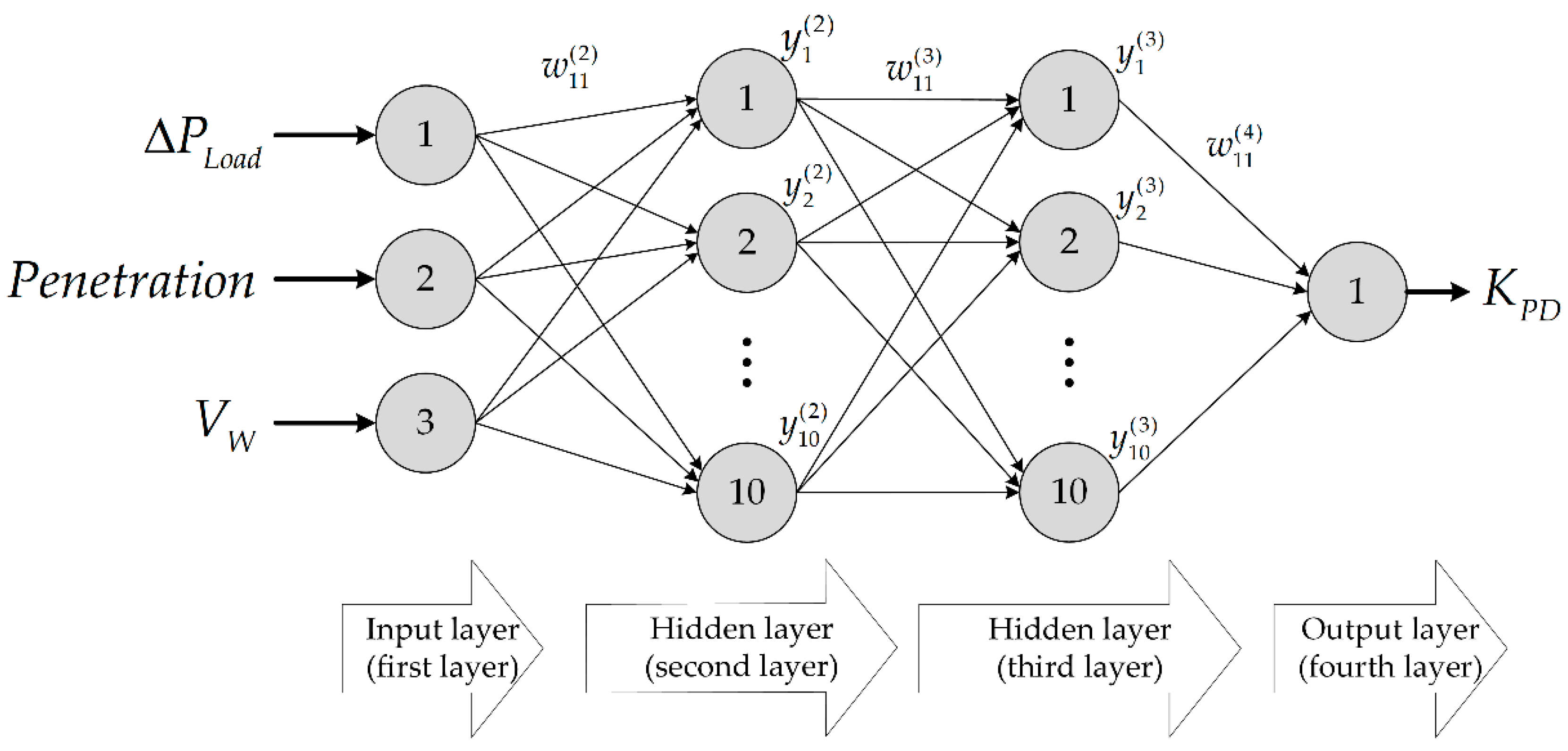
As shown in Figure 1, the gain for the supplementary frequency controller is adjusted by ANN based on the present load disturbance (), wind penetration, and wind speed (), which are provided as the inputs to the ANN. The output of the ANN is the desired gain for the DFIG supplementary frequency controller. A feedforward neural network with two hidden layers and ten nodes for each layer as shown in Figure 7 was used [21].

Figure 7.
ANN for a frequency controller. load disturbance.
As shown in Figure 7, the output of the jth node in the nth layer, , is a nonlinear function of the outputs from the nodes in the (n − 1)th layers, as described below:
where is the connection weight between the ith node in the (n − 1)th layer, and the jth node in the nth layer and g is a nonlinear hyperbolic-tangent activation function.
The desired droop gain is obtained from the following equation:
Before the ANN can be employed to yield the desired droop gain , the connection weights must be determined using a set of training patterns. In this paper, a total of 27,920 training patterns were used in the ANN training process to cover different combinations of , wind penetration, and .
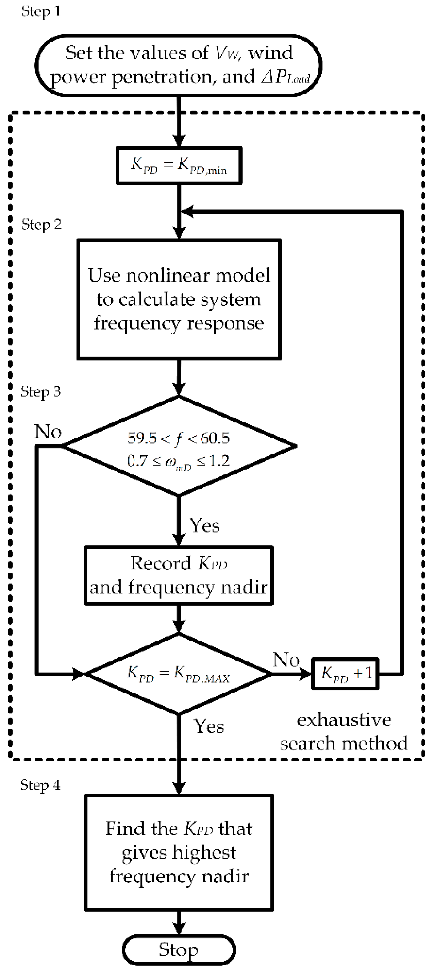
The flow chart in Figure 8 was used to reach the desired ANN output () for a particular combination of ANN inputs (, wind penetration, and ).

Figure 8.
Flow chart to create training patterns.
The procedures to create training patterns are described as follows:
- Step 1
- Set the , wind power penetration, and that are considered in this work and the minimum value of the .
- Step 2
- Solve the dynamic frequency response of the system using the nonlinear model in Figure 1.
- Step 3
- If the dynamic response satisfies the requirements defined in Equation (3), record the and the frequency nadir.
- Step 4
- Find the that gives the highest frequency nadir under different scenarios and record the , wind power penetration, , and .
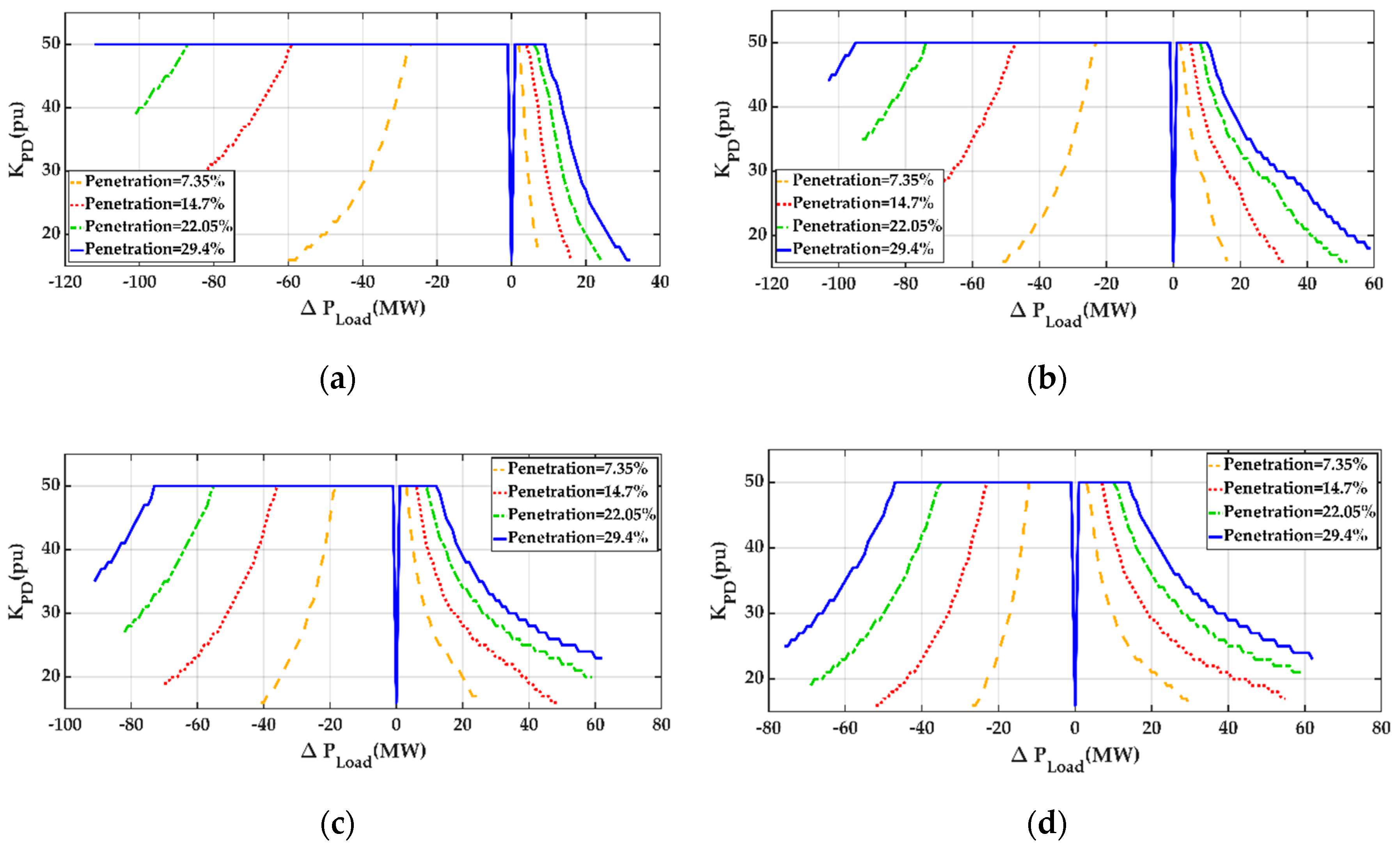
The created training patterns are depicted in Figure 9 for the cases under four different wind speeds: = 9 m/s, = 10 m/s, = 11 m/s, and = 12 m/s.

Figure 9.
Training patterns under four different wind speeds: (a) = 9 m/s, (b) = 10 m/s, (c) = 11 m/s, and (d) = 12 m/s.
Among the 27,920 training patterns as shown in Figure 9, 80% were used for training and 20% were used for testing. In the ANN training process, the connection weights between the inputs nodes, the nodes in the two hidden layers, and the output node are determined based on the criterion to make the droop gain from the ANN as close to the optimal gain in the training pattern as possible. In other words, the objective is to minimize the cost function, as described below:
where and are the droop gain from the ANN and the optimal droop gain in the training pattern. Detailed procedures to determine the connection weights from the cost function in Equation (8) can be found in [21].
5. Case Studies
To demonstrate the effectiveness of the proposed ANN-based supplementary frequency controller, the local power system as shown by the block diagram in Figure 1 with the parameters in the Appendix A was simulated using MATLAB/SIMULINK. The results are described below.
5.1. Comparison of ANN-Based Controller and Fixed-Gain Controller under Different Load Disturbances
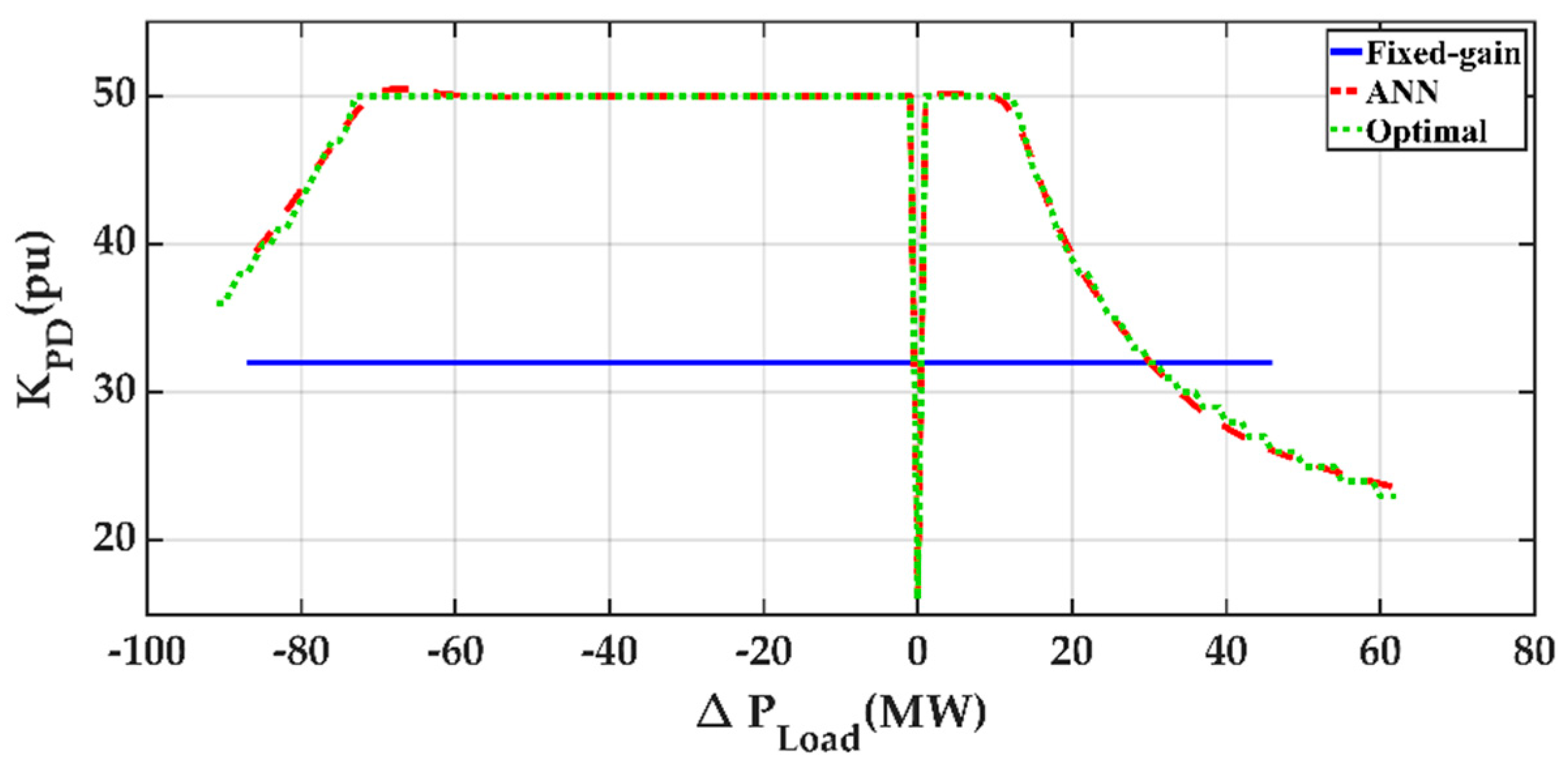
Figure 10 compares the droop gain from the ANN-based controller, optimal controller, and fixed-gain controller with = 32 under different load disturbances. It is observed from Figure 10 that the droop gain from the ANN-based controller is very close to those from the optimal controller. However, the ANN-based controller can be used for online applications, since the droop gain is reached in a very efficient manner. On the other hand, the optimal controller cannot be employed in real-time situations, since a great number of simulations are performed in order to reach the optimal droop gain by using the exhaustive search method.

Figure 10.
Droop gain from the ANN-based controller, optimal controller, and fixed-gain controller (wind penetration = 29.4% and = 11 m/s) under different load disturbances.
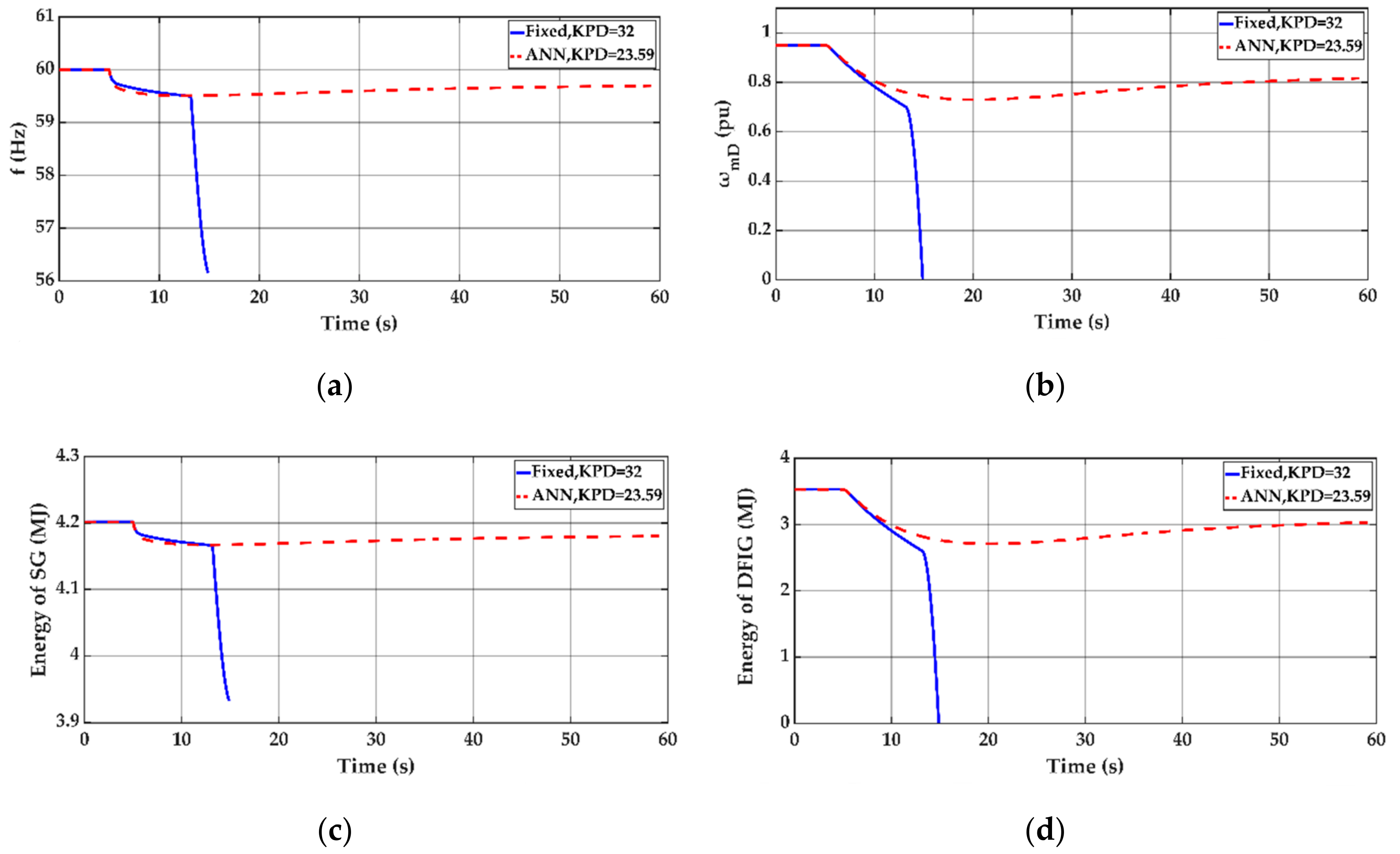
Figure 11 depicts the frequency, DFIG speed, SG energy, and DFIG energy for a load disturbance of = 62 MW. It is observed from Figure 11 that, in the case of a load increase of 62 MW, the DFIG speed fails to remain in the allowable range of 0.7 pu 1.2 pu when the controller gain is fixed at 32. On the other hand, the satisfactory frequency and speed responses can be achieved by the ANN-based controller by adapting the gain to a lower value of 23.59.

Figure 11.
Dynamic response curves from the ANN-based controller and fixed-gain controller ( = 62 MW, wind penetration = 29.4%, and = 11 m/s). (a) Frequency, (b) DFIG speed, (c) SG energy, and (d) DFIG energy.
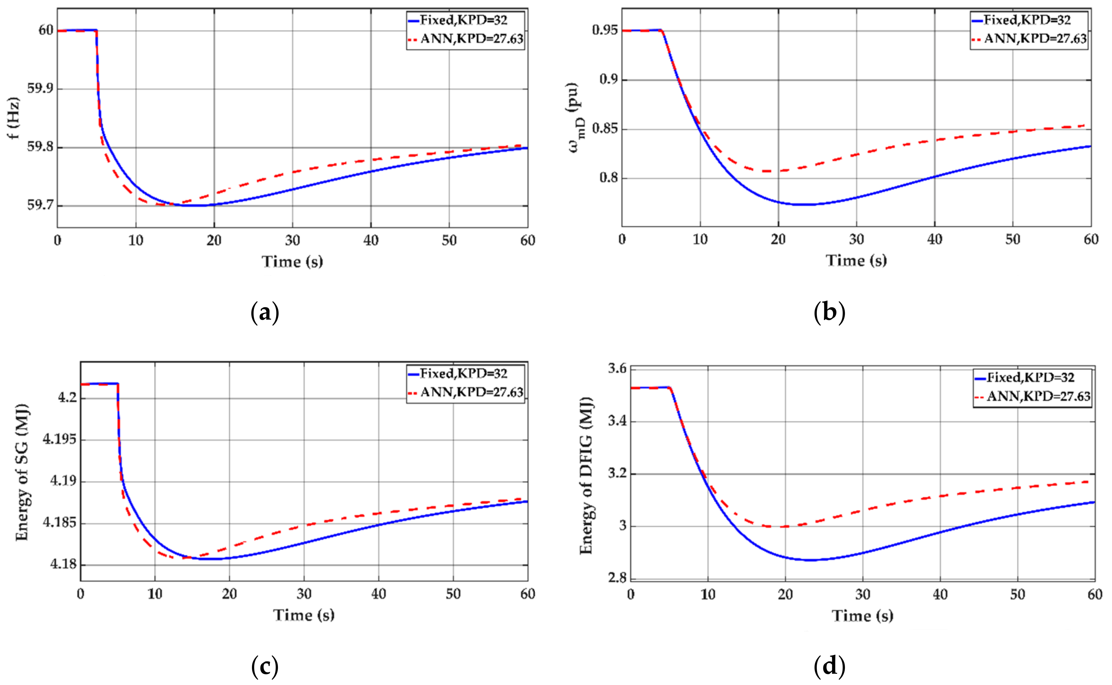
The frequency, DFIG speed, SG energy, and DFIG energy for a load disturbance of = 40 MW are depicted in Figure 12. As the observation of the response curves in Figure 12 indicates, the ANN-based controller gives better frequency and speed responses than the fixed-gain controller.

Figure 12.
Dynamic response curves from the ANN-based controller and fixed-gain controller ( = 40 MW, wind penetration = 29.4%, and = 11 m/s). (a) Frequency, (b) DFIG speed, (c) SG energy, and (d) DFIG energy.
5.2. Comparison of the ANN-Based Controller and Fixed-Gain Controller under Different Wind Power Penetrations
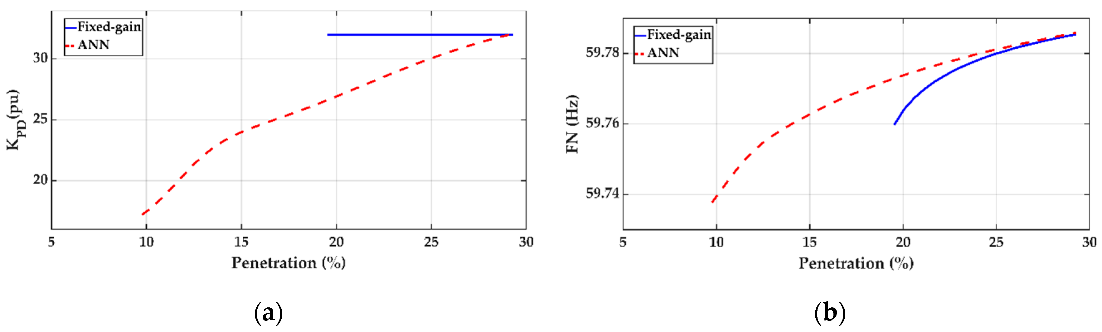
The droop gain and FN from the ANN-based controller and fixed-gain controller under different wind power penetrations are depicted in Figure 13. It is observed from Figure 13 that the ANN-based controller gives better frequency than the fixed-gain controller, since its droop gain is varied according to the percentage of the wind power penetration.

Figure 13.
Droop gain and frequency nadir from the ANN-based controller and fixed-gain controller ( = 30 MW and = 11 m/s) under different penetrations. (a) Droop gain and (b) frequency nadir (FN).
5.3. Comparison of the ANN-Based Controller and Fixed-Gain Controller under Different Wind Speeds
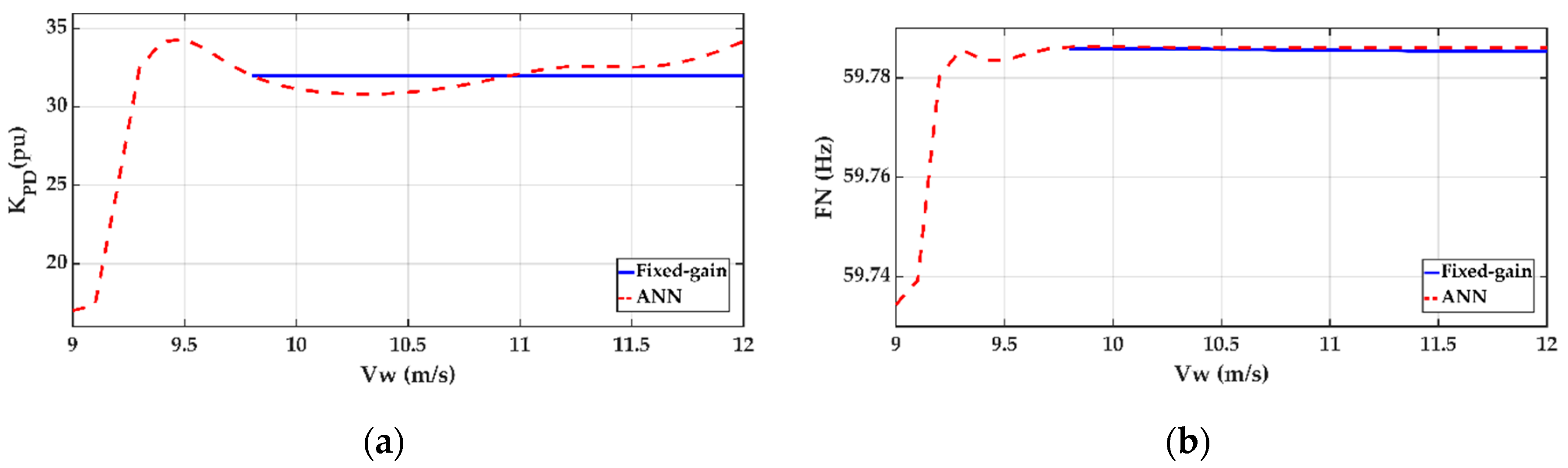
In order to examine the dynamic performance of the ANN-based controller under different wind speed conditions, the droop gain and FN under different wind speeds are shown in Figure 14. It is observed from Figure 14 that it is impossible to find a feasible solution that satisfies the frequency and speed constraints by using the fixed-gain controller when the wind speed is lower than 9.8 m/s. However, satisfactory frequency nadir can still be achieved by the ANN-based controller. It is also observed that the ANN-based controller gives better FN than the fixed-gain controller, since the droop gain is varied with the changing wind speed.

Figure 14.
Droop gain and frequency nadir from the ANN-based controller and fixed-gain controller ( = 30 MW and wind penetration = 29.4%) under different wind speeds. (a) Droop gain and (b) frequency nadir (FN).
5.4. ANN Performance Test for Untrained Cases
A major feature of the ANN is that, once the ANN is trained using an appropriate set of training patterns, it can be used to generate the desired output (controller gain ) directly even when the input variables (, wind penetration, and wind speed) are not within the set of training patterns. Time-consuming simulations for the untrained cases can thus be avoided.
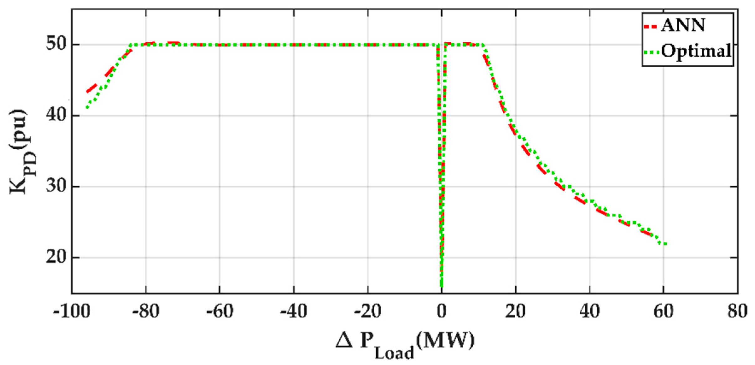
Figure 15 compares the droop gain from the ANN-based controller and the optimal controller for the case of = 10.5 m/s, which was not included in the training patterns. It is observed from Figure 15 that the ANN-based controller can yield droop gains that are very close to the optimal gain from the exhaustive search method even when the wind speed ( = 10.5 m/s) is different from the wind speeds in all training patterns for the ANN.

Figure 15.
Droop gain from the ANN-based controller and optimal controller ( = 10.5 m/s and wind penetration = 29.4%).
5.5. Feasible Operating Regions for the ANN-Based Controller
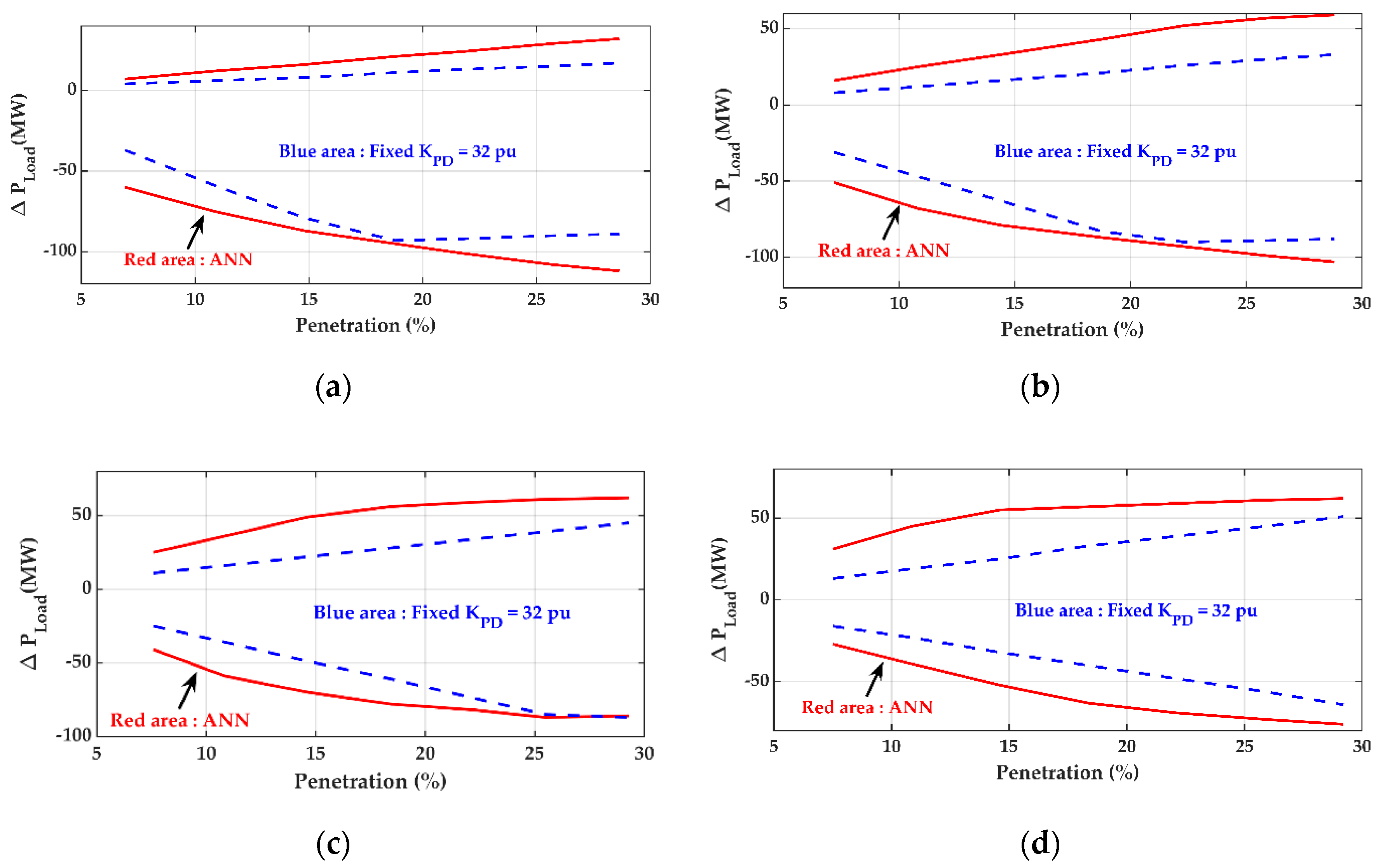
The feasible operating regions for the ANN-based controller and fixed-gain controller are compared in Figure 16 for cases under four different wind speeds: = 9 m/s, = 10 m/s, = 11 m/s, and = 12 m/s. It is concluded from Figure 16 that the proposed ANN-based controller with variable gain provides a wider operating zone than the fixed-gain controller.

Figure 16.
Comparison of the feasible operating regions for the ANN-based controller and fixed-gain controller. (a) = 9 m/s, (b) = 10 m/s, (c) = 11 m/s, and (d) = 12 m/s.
6. Conclusions
An ANN was designed to yield the droop gain for the supplementary frequency controller of a DFIG wind farm under different load disturbances, wind penetrations, and wind speeds. The effects of the load disturbances, wind penetrations, and wind speeds on the optimal gain were first studied. It was found that the load disturbance, wind penetration, and wind speed had significant impacts on the optimal controller gain. Therefore, the three variables were employed as the inputs to the ANN, and the output of the ANN was the desired droop controller gain. The specific conclusions are as follows:
- The droop gain decreases with the increasing magnitude of the load disturbances.
- The droop gain should be increased when the wind power penetration is increased.
- The droop gain increases with the increasing wind speed.
- The ANN-based controller yields essentially the same droop gain as the optimal controller using the exhaustive search method. However, the ANN-based method is more efficient than the exhaustive search method, since time-consuming simulations can be avoided after the ANN is trained. Therefore, the ANN-based controller can be used in online applications, and the optimal controller using the exhaustive search method cannot be employed for real-time applications.
- A major feature of the ANN-based controller is that it can be employed to provide the desired droop gain without the need to perform additional simulations, even when the load disturbance, wind penetration, and wind speed are not within the set of training patterns.
- By using the ANN-based controller with different gains under different operating conditions, the feasible operating regions under different wind speeds and different wind penetrations can be expanded.
- In practical applications, the load disturbance can be estimated from the rate of change of frequency (). The wind penetration is computed using the rated capacities of online units. The wind speed is assumed to be available at the local wind farm.
Author Contributions
Conceptualization, methodology, software, validation, investigation, data curation, and visualization, T.-H.C.; writing—review and editing, Y.-C.H.; and writing—original draft, supervision, and project administration, Y.-Y.H. All authors have read and agreed to the published version of the manuscript.
Funding
This research was funded by Ministry of Science and Technology of Taiwan grant number MOST 106-2221-E-002-147-MY3 and the APC was funded by Ministry of Science and Technology of Taiwan.
Acknowledgments
This work was supported by the Ministry of Science and Technology of Taiwan under Contract MOST 106-2221-E-002-147-MY3. Cheng-Hung Chuang and Tien-Kuei Lu provided valuable system data and comments.
Conflicts of Interest
The authors declare that they have no known competing financial interests or personal relationships that could have appeared to influence the work reported in this paper.
Nomenclature
| D | load damping |
| equivalent inertia time constants of synchronous machine and DFIG | |
| nominal frequency and system frequency | |
| power fractions of the high, intermediate, and low-pressure turbines | |
| maximum power point tracking constant | |
| DFIG supplementary proportional controller gain | |
| synchronous machine droop and integral controller gains | |
| control signal, speed relay output signal, and steam valve position of the synchronous machine | |
| mechanical output power of the high, intermediate, and low-pressure turbines | |
| Load demand | |
| electromagnetic power of DFIG | |
| mechanical power of synchronous machine | |
| speed relay and servo-motor time constants of the synchronous machine | |
| steam chest, reheater, and crossover time constants of the synchronous machine | |
| mechanical torque and electromagnetic torque of DFIG | |
| electromagnetic torque command of DFIG for MPPT operation | |
| DFIG torque command | |
| DFIG speed | |
| wind speed | |
| wind turbine power coefficient | |
| area swept by the wind turbine blades | |
| air density | |
| wind turbine tip speed ratio and blade pitch angle | |
| incremental quantity |
Appendix A
Synchronous machine:
Rated power: 480 MVA.
Machine parameters: = 3.3 s.
Speed governor and turbine:
Droop and integral controller gains: = 20 and = 0.1.
Speed relay and servo-motor time constants: = 0.1 s and = 0.3 s.
Steam chest, reheater and crossover time constants: = 0.68 s, = 5.3 s, and = 0.58 s.
Power fractions: = 0.241, = 0.399, and = 0.360.
DFIG:
Rated power: 200 MVA.
Machine parameters: = 3.5 s.
Load parameters:
Load damping coefficient: D = 1.
References
- Bureau of Energy, Ministry of Economic Affairs, Wind Power Generation Four Years Project. Taiwan, August 2017. Available online: https://www.moeaboe.gov.tw/ECW/populace/content/ContentDesc.aspx?menu_id=5493 (accessed on 12 October 2020).
- Shahabi, M.; Haghifam, M.R.; Mohamadian, M.; Nabavi-Niaki, S.A. Microgrid dynamic performance improvement using a doubly fed induction wind generator. IEEE Trans. Energy Convers. 2009, 24, 137–145. [Google Scholar] [CrossRef]
- Lee, J.; Jang, G.; Muljadi, E.; Blaabjerg, F.; Chen, Z.; Kang, Y.C. Stable short-term frequency support using adaptive gains for a DFIG-based wind power plant. IEEE Trans. Energy Convers. 2016, 31, 1068–1079. [Google Scholar] [CrossRef]
- Arani, M.F.M.; Mohamed, Y.A.I. Analysis and impacts of implementing droop control in DFIG-based wind turbines on microgrid/weak-grid stability. IEEE Trans. Power Syst. 2015, 30, 385–396. [Google Scholar] [CrossRef]
- Arani, M.F.M.; Mohamed, Y.A.I. Dynamic droop control for wind turbines participating in primary frequency regulation in microgrids. IEEE Trans. Smart Grid 2018, 9, 5742–5751. [Google Scholar] [CrossRef]
- Yang, J.; Chen, Y.; Hsu, Y. Small-signal stability analysis and particle swarm optimisation self-tuning frequency control for an islanding system with DFIG wind farm. IET Gener. Transm. Distrib. 2019, 13, 563–574. [Google Scholar] [CrossRef]
- Hwang, M.; Muljadi, E.; Park, J.; Sørensen, P.; Kang, Y.C. Dynamic droop-based inertial control of a doubly-fed induction generator. IEEE Trans. Sustain. Energy 2016, 7, 924–933. [Google Scholar] [CrossRef]
- Vidyanandan, K.V.; Senroy, N. Primary frequency regulation by deloaded wind turbines using variable droop. IEEE Trans. Power Syst. 2013, 28, 837–846. [Google Scholar] [CrossRef]
- Ramtharan, G.; Ekanayake, J.B.; Jenkins, N. Frequency support from doubly fed induction generator wind turbines. IET Renew. Power Gener. 2007, 1, 3–9. [Google Scholar] [CrossRef]
- Li, Y.; Xu, Z.; Zhang, J.; Wong, K.P. Variable gain control scheme of DFIG-based wind farm for over-frequency support. Renew. Energy 2018, 120, 379–391. [Google Scholar] [CrossRef]
- Pradhan, C.; Bhende, C.N.; Samanta, A.K. Adaptive virtual inertia-based frequency regulation in wind power systems. Renew. Energy 2018, 115, 558–574. [Google Scholar] [CrossRef]
- Ochoa, D.; Martinez, S. Frequency dependent strategy for mitigating wind power fluctuations of a doubly-fed induction generator wind turbine based on virtual inertia control and blade pitch angle regulation. Renew. Energy 2018, 128, 108–124. [Google Scholar]
- Camblong, H.; Vechiu, I.; Guillaud, X.; Etxeberria, A.; Kreckelbergh, S. Wind turbine controller comparison on an island grid in terms of frequency control and mechanical stress. Renew. Energy 2014, 63, 37–45. [Google Scholar] [CrossRef]
- Papaefthymiou, S.V.; Lakiotis, V.G.; Margaris, I.D.; Papathanassiou, S.A. Dynamic analysis of island systems with wind-pumped-storage hybrid power stations. Renew. Energy 2015, 74, 544–554. [Google Scholar] [CrossRef]
- Mauricio, J.M.; Marano, A.; Gomez-Exposito, A.; Ramos, J.L.M. Frequency regulation contribution through variable-speed wind energy conversion systems. IEEE Trans. Power Syst. 2009, 24, 173–180. [Google Scholar] [CrossRef]
- Kayikci, M.; Milanovic, J.V. Dynamic contribution of DFIG-based wind plants to system frequency disturbances. IEEE Trans. Power Syst. 2009, 24, 859–867. [Google Scholar] [CrossRef]
- Margaris, I.D.; Papathanassiou, S.A.; Hatziargyriou, N.D.; Hansen, A.D.; Sorensen, P. Frequency control in autonomous power systems with high wind power penetration. IEEE Trans. Sustain. Energy 2012, 3, 189–199. [Google Scholar]
- Vyver, J.V.D.; Kooning, J.D.M.D.; Meersman, B.; Vandevelde, L.; Vandoorn, T.L. Droop control as an alternative inertial response strategy for the synthetic inertia on wind turbines. IEEE Trans. Power Syst. 2016, 31, 1129–1138. [Google Scholar] [CrossRef]
- Wilches-Bernal, F.; Chow, J.H.; Sanchez-Gasca, J.J. A fundamental study of applying wind turbines for power system frequency control. IEEE Trans. Power Syst. 2016, 31, 1496–1505. [Google Scholar] [CrossRef]
- Hafiz, F.; Abdennour, A. An adaptive neuro-fuzzy inertia controller for variable-speed wind turbines. Renew. Energy 2016, 92, 136–146. [Google Scholar] [CrossRef]
- Haykin, S. Neural Networks and Learning Machines, 3rd ed.; Pearson: Upper Saddle River City, NJ, USA, 2008. [Google Scholar]
- Taiwan Power Company. Power System Operation Guide; Taiwan Power Company: Taipei City, Taiwan, 2020. [Google Scholar]
- Zhang, Z.; Sun, Y.; Lin, J.; Li, G. Coordinated frequency regulation by doubly fed induction generator-based wind power plants. IET Renew. Power Gener. 2012, 6, 38–47. [Google Scholar] [CrossRef]
© 2020 by the authors. Licensee MDPI, Basel, Switzerland. This article is an open access article distributed under the terms and conditions of the Creative Commons Attribution (CC BY) license (http://creativecommons.org/licenses/by/4.0/).