Article

Study on the Fracture Law of Inclined Hard Roof and Surrounding Rock Control of Mining Roadway in Longwall Mining Face

1
School of Energy Engineering, Xi’an University of Science and Technology, Xi’an 710054, China
2
Key Laboratory of Western Mines and Hazard Prevention of China Ministry of Education, Xi’an University of Science and Technology, Xi’an 710054, China
3
Key Laboratory of Coal Resource Exploration and Comprehensive Utilization, Ministry of Land and Resources, Xi’an 710021, China
4
Shenhua Xinjiang Energy Ltd., Wulumuqi 830027, China
*
Author to whom correspondence should be addressed.
Energies 2020, 13(20), 5344; https://doi.org/10.3390/en13205344
Submission received: 23 September 2020 / Revised: 9 October 2020 / Accepted: 12 October 2020 / Published: 14 October 2020

Abstract

:
In the inclination direction, the fracture law of a longwall face roof is very important for roadway control. Based on the W1123 working face mining of Kuangou coal mine, the roof structure, stress and energy characteristics of W1123 were studied by using mechanical analysis, model testing and engineering practice. The results show that when the width of W1123 is less than 162 m, the roof forms a rock beam structure in the inclined direction, the floor pressure is lower, the energy and frequency of microseismic (MS) events are at a low level, and the stability of the section coal pillar is better. When the width of W1123 increases to 172 m, the roof breaks along the inclined direction, forming a double-hinged structure, the floor pressure is increased, and the frequency and energy of MS events also increases. The roof gathers elastic energy release, and combined with the MS energy release speed it can be considered that the stability of the section coal pillar is better. As the width of W1123 increases to 184 m, the roof in the inclined direction breaks again, forming a multi-hinged stress arch structure, and the floor pressure increases again. MS high-energy events occur frequently, and are not conducive to the stability of the section coal pillar. Finally, through engineering practice we verified the stability of the section coal pillar when the width of W1123 was 172 m, which provides a basis for determining the width of the working face and section coal pillar under similar conditions.

Graphical Abstract

1. Introduction

China has rich reserves of thick coal seams, accounting for more than 45% of the country’s total reserves. Since the 1980s, China has conducted a lot of research on the mining methods of thick coal seams, and has formed fully mechanized top coal caving mining (fully mechanized caving mining), slicing mining, and large mining height mining methods. Considering the factors of the thickness of the coal seam, the mining height of the shearer, and mining benefits, when the thickness of the coal seam is greater than 8 m, fully mechanized caving mining is generally adopted. Fully mechanized caving mining has the advantages of high productivity, efficiency and safety, but as the width of the fully mechanized caving face increases, the lateral pressure of the face increases, causing the overlying strata to undergo violent migration and collapse, which affects the stability of the section coal pillar and the safety of workers [1,2,3].
Many scholars have conducted research on the fracture structure and lateral supporting pressure of the roof slab of the working face. Wang et al. [4] analyzed the relationship between the fracture structure of the basic roof and the stability of the coal pillar, proposed three basic roof fracture structures, and studied the internal stress distribution and deformation characteristics of the coal pillar under different fracture structure conditions; Zhu et al. [5] researched the movement laws and failure characteristics of the rock strata above the working face, and proposed a method to reduce the deformation of the rock strata above the working face by cutting the roof of the working face, which provided a new idea for maintaining the stability of the working face roadway. Zhang et al. [6] proposed a roof directional blasting pre-separation technology in view of the widespread difficulty of roadway support in longwall working faces, which effectively solved the phenomenon of mine pressure concentration in longwall working faces. Zhang et al. [7] studied the coal pillars of a fully mechanized caving face under high-intensity mining conditions, and believed that the large lateral fracture step of the working face under high-intensity mining conditions resulted in the internal stress field being larger than the conventional working face. Coal pillar width, the influence of repeated mining, basic roof failure state and large section roadway should be considered. Cui [8,9] and others used theoretical analysis, numerical simulation, and similar simulation experimental methods to study the roof fracture structure and overlying rock migration law of working faces, and found that the superposition of mining disturbance stress in adjacent working faces caused the working face to be the main factor of rock burst. Dai et al. [10,11] used mechanical analysis, similar simulation experiments and other methods to study the roof-breaking structure of the working face and the analysis of the section coal pillar force, and proposed to improve the stability of the roadway confining pressure by blasting the working face roof.
In the aspect of research on stability of coal pillars and roadways along gobs in coal mining face. Kang et al. [12] proposed that the essence of roadway support is to maintain the integrity of the confining pressure structure, form a support stress field, and improve the overall stability of the roadway surrounding rock. Shen et al. [13] used stress sensors, microseismic (MS) monitoring systems and other methods to study the stress evolution law and rock formation failure characteristics in the stress concentration area during face mining, and found that the MS positioning signal active area and stress dissimilation area mostly appeared in the vicinity of faults, joints and other geological structures that provide a basis for regional monitoring and early warning of working faces. Meng et al. [14] analyzed the structural characteristics and movement laws of the surrounding rock of the working face and believed that in the deep mining process, the working face roadway is affected by the superposition of high ground stress and mining disturbance stress, and it is difficult to maintain its own stability. Yield-resistant sand column (YRSC) sidewall support technology ensures the stability of the surrounding rock structure of the working face roadway. Yin et al. [15] conducted on-site monitoring of the basic roof fracture location and roof movement characteristics, combined with the asymmetric development characteristics of roof coal samples, and proposed asymmetric support technology for large deformation along gob roadways, which has a good effect on the surrounding rock of the roadway. Control effect. Cha et al. [16] analyzed the breaking characteristics of the key rock blocks of the basic roof, and studied the influence of the breaking structure of the basic roof and the load of the overlying strata on the stability of the coal pillar, and proposed the combined support of bolts, anchor nets, and anchor cables. The protection scheme improves the stability of the surrounding rock of the roadway. Wang et al. [17] studied the coal pillar size of the inclined thick coal seam section and proposed the joint support of adjacent roadways between the staggered and outer staggered sections. The results showed that the joint support scheme of adjacent roadways between the sections is more beneficial to the roadway if there is deformation control of surrounding rock.
The aforementioned scholars have made useful explorations on the roof fracture structure of the coal mining face and the stability of the section coal pillar, laying the foundation for subsequent research, but for the repeated mining of gently inclined and extra-thick coal seams, the thick and hard roof in the inclined direction There are relatively few studies on the fracture state and its influence on the stability of the section coal pillar, so more in-depth research is necessary.

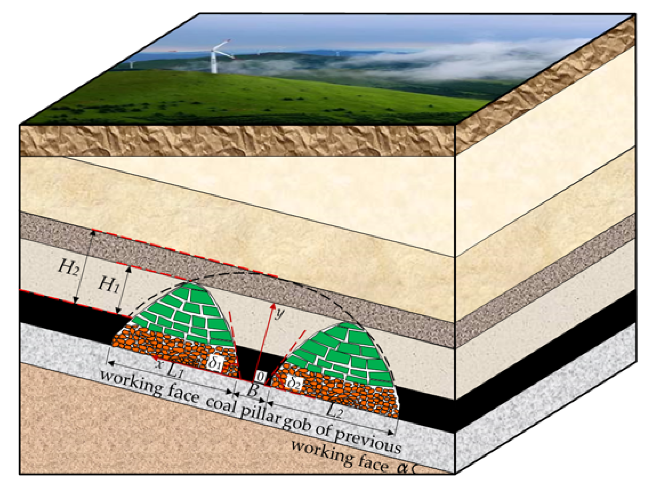
2. The Inclined Fracture Structure and Mechanical Model of the Working Face Roof

As the width of the longwall working face (working face) increases, the roof breaks more fully after mining. Through simplified analysis of the roof fracture structure and stress state of the working face, a mechanical model of the thick and hard roof inclined fracture structure under the conditions of different widths of the working face is established, and the force characteristics of the section coal pillar under different structural states are analyzed.

2.1. Inclined Fracture Structure of Working Face Roof

Figure 1 shows the fracture structure of the thick and hard roof under different widths of the working face. Figure 1a shows the structural characteristics of the thick and hard roof tending to fracture when the working face width is short. Figure 1b shows the structural characteristics of a thick and hard roof tending to fracture when the working face width is medium length. Figure 1c shows the structural characteristics of a thick and hard roof tending to fracture when the working face is longer. As shown in Figure 1, when the width of the working face is short, after the coal seam is mined, the thick and hard roof is in the form of a “rock beam” structure along the slope of the working face. As the width of the working face increases, the “rock beam” structure breaks in the middle of the working face and exists in the form of a double-hinged structure. When the width of the working face is further increased, the thick and hard roof of the working face breaks again, and the thick and hard roof is in the form of a multi-articulated stress arch structure along the inclined direction of the working face.

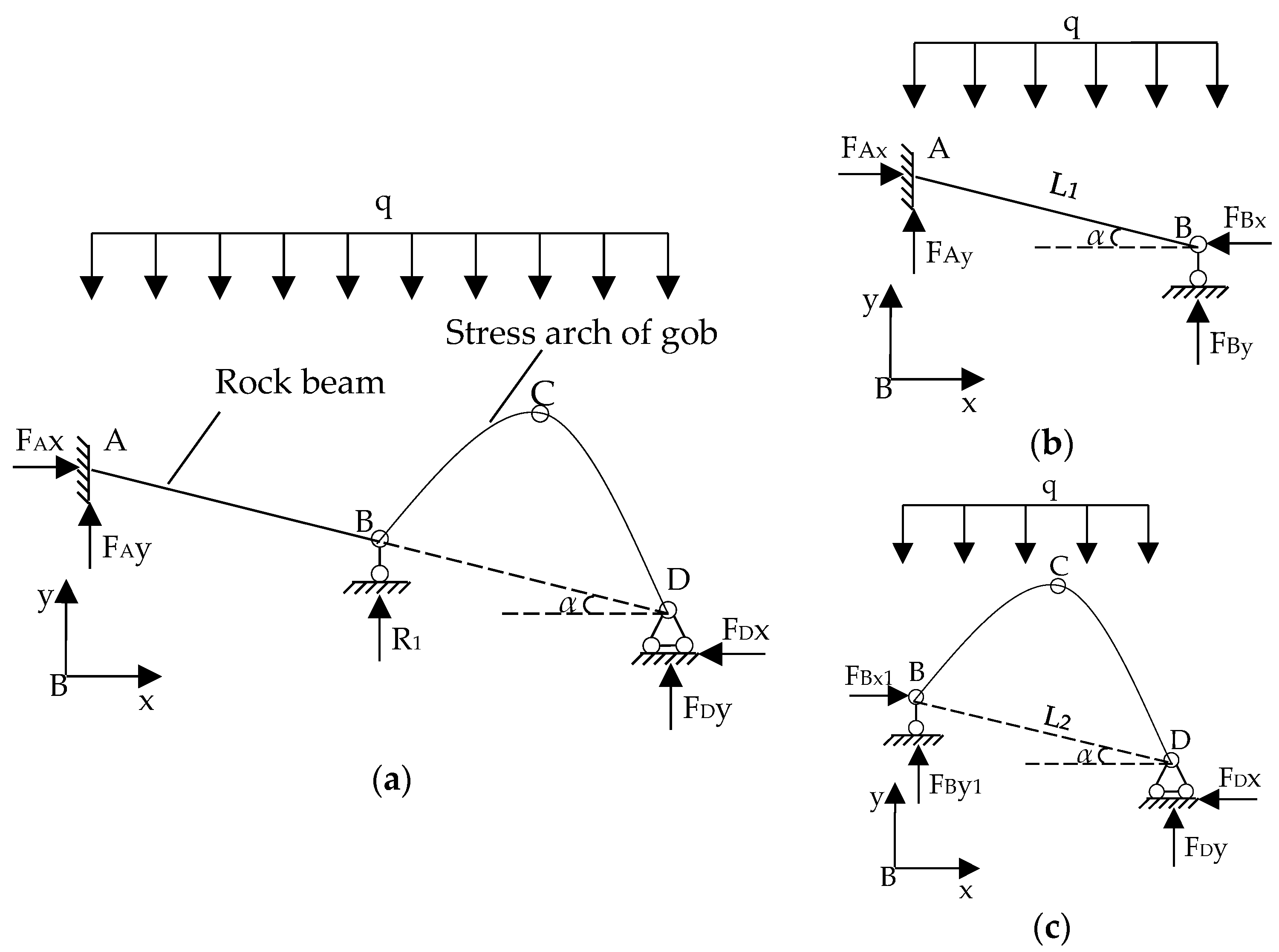
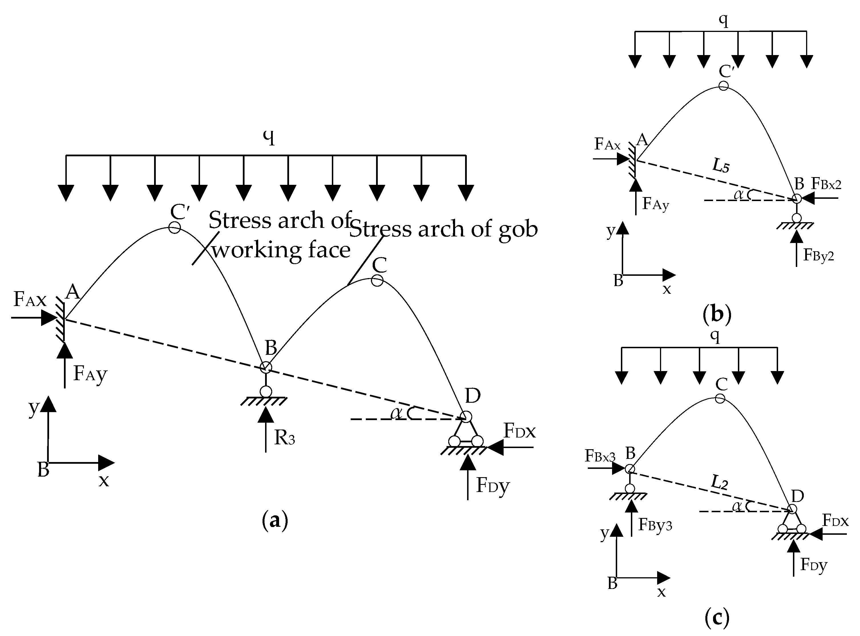
2.2. Mechanical Model

Figure 2 shows the geological model of the coal pillar load during the mining process of two adjacent working faces. The section coal pillar load σ comes from the self-weight stress σq of the overlying strata of the section coal pillar, the load σu transmitted by the strata in the gob of the upper section, and the load σh transmitted by the overlying strata during the mining process of this working face.
The following formula can be used to express the section coal pillar load σ:
σ = σq + σu + σh
The self-weight stress σ0 generated by the rock formation at different positions of the working face are, respectively,
i = 1 n M i γ i = { B γ H 2 cos α H 1 cot δ 2 < x H 1 cot δ 1 1 2 γ H 1 2 cot δ cos α H 1 cot δ < x H 2 cot δ L γ Hcos α H 2 cot δ < x L
In formula (2), γ is the average bulk density of the overlying strata, kN/m3; H is the depth of the working face, m;H1 is the height of the collapse zone of the strata, m; H2 is the height of the fracture zone in the strata, m; δ1 is the breaking angle of the side strata of the coal mining face, °; δ2 is the breaking angle of the side strata in the gob, °; B is the width of the coal pillar in the section, m; L1 is the width of the coal mining face, m; L2 is the width of the gob in the upper section, m; and α is the inclination of the coal seam, °.
Then the self-weight stress σq generated by the rock above the coal pillar section,
σ q = B γ H 2 cos α + 1 2 γ H 1 2 cot δ 1 cos α + 1 2 γ H 1 2 cot δ 2 cos α = γ cos α [ B H 2 + 1 2 H 1 2 ( cot δ 1 + cot δ 2 ) ]
σu and σh are closely related to the roof fracture structure of the working face. Through a simplified analysis of the roof fracture structure under different working face width conditions, the mechanical model of the roof fracture structure can be established.
Figure 3 shows the inclined fracture structure mechanics mode when the working face width is short. In Figure 3a, A is a fixed bearing and B is a single hinge bearing. With point B as the origin of the coordinates, the horizontal direction is the positive direction of the x-axis, and the vertical direction is the positive direction of the y-axis, the coordinate system Bxy is established. Since the vertical projections of the two adjacent working faces with a gentle slope are much smaller than the buried depth, the overburden load on the working face can be simplified to a uniform load q,
q = γ H cos α
Because the side roof of the mined-out area in the upper section is affected by the mining disturbance of the upper section working face and the mining disturbance of the current working face, under the effect of time, the roof edge of the upper section working face is finally in the form of a multi articulated structure, represented by stress arch BCD.
Figure 3b,c is respectively the force analysis diagrams of the structural isolator. The force of the structure is a statically indeterminate problem. The structure is analyzed by the method of structural mechanics. The AB section and BCD section of the isolator are, respectively, taken to perform the restraint reaction force FBy, FBy1 and the section coal pillar support reaction force R1. Analysis and solution:
ΣFy: FAy + FBy − qL1 =0
Then the bearing reaction force:
σh =FBy = qL1 cosα/2 = γH1L1cosα2/2
The overall balance of the full arch, the vertical reaction forces of the two supports are obtained from the moment balance conditions ΣMD = 0 and ΣMB = 0:
σu= FBy1 = qL2 cosα/2 = γH1L2cosα2/2
Substituting Formula (3), Formula (6), and Formula (7) into Formula (1) can be obtained, the section coal pillar support reaction force R1:
σ = R 1 = F By + F By 1 + σ q = 1 2 γ H L 1 cos α 2 + 1 2 γ H L 2 cos α 2 + γ cos α [ B H 2 + 1 2 H 1 2 ( cot δ 1 + cot δ 2 ) ] = 1 2 γ H cos α 2 ( L 1 + L 2 ) + 1 2 γ H 1 2 cos α ( cot δ 1 + cot δ 2 ) + B γ H 2 cos α
Because the rock material has the characteristic that the tensile strength is much smaller than the compressive strength, the suspended rock beam will undergo tensile failure. The maximum bending stress of the rock beam occurs in the middle of the suspended rock beam, and the maximum bending stress Mmax is [1]:
Mmax = qL02/8
The ultimate tensile strength of the suspended rock beam is [σt]. According to the relationship between stress and bending moment, the ultimate bending moment of the suspended rock beam fracture can be obtained as [18]:
Mmax = [σt]h2/6
In the formula, h is the thickness of the suspended rock beam. When M ≥ Mmax, the rock beam will break, so the limit fracture length of the suspended rock beam is L0 [1]:
L 0 = 4 [ σ t ] h 2 3 q = 2 h [ σ t ] γ H cos α
Figure 4 shows the mechanical model of the roof inclined to fracture when the working face width is medium. As shown in Figure 4a, when the working face width L1 ≥ L0, the suspended rock beam breaks, forming a double-articulated structure. Figure 4b,c is the AB’ and B’B sections of the double-articulated isolator, respectively. FB’y is the reaction force of the gangue support in the gob, and R2 is the section under this structural condition with regard to the reaction force of coal pillar support.
Using the statics equation to analyze and solve the restraint force FB’y and the section coal pillar support reaction force R2:
σ h = F B y = 1 2 γ H cos α ( L 3 cos β + L 4 cos α )
In the formula, L3 is the length of the rock block of section AB’; L4 is the length of the rock block of the B’B section, the dip angle of the rock block of the AB’ section is β, and the rock block of the B′B section is nearly horizontal.
Substituting Formula (3), Formula (7), and Formula (12) into Formula (1) can be obtained, the section coal pillar support reaction force R2:
σ = R 2 = F B y + σ u + σ q = 1 2 γ H cos α ( L 3 cos β + L 4 cos α ) + 1 2 γ H L 2 cos α 2 + γ cos α [ B H 2 + 1 2 H 1 2 ( cot δ 1 + cot δ 2 ) ] = 1 2 γ H cos α ( L 2 cos α + L 3 cos β + L 4 cos α ) + 1 2 γ H 1 2 cos α ( cot δ 1 + cot δ 2 ) + B γ H 2 cos α
Figure 5 shows the mechanical model of the roof tending to fracture when the working face is longer. As the width of the working face increases, the double articulated rock block breaks again. In Figure 5a, A is a fixed bearing, B is a single hinged bearing, BC’D is the lateral stress arch of the working face, FBy2 is the restraining force of the working face arch foot, and R3 is the section coal pillar support under this structural condition with regard to the seat reaction force.
Figure 5b,c is the AC’B section and BCD section of the isolator, respectively. Static equations are used to analyze and solve the restraint force FBy2 and the coal pillar support reaction force R3.
σ h = F B y 2 = 1 2 L 5 γ H cos α 2
In the formula, L5 is the length of the working face. Substituting Formula (3), Formula (7), and Formula (14) into Formula (1) can be obtained, the section coal pillar support reaction force R3:
σ = R 3 = F By 2 + σ u + σ q = 1 2 L 5 γ Hcos α 2 + 1 2 L 2 γ Hcos α 2 + γ cos α [ BH 2 + 1 2 H 1 2 ( cot δ 1 + cot δ 2 ) ] = 1 2 γ Hcos α 2 ( L 5 + L 2 ) + 1 2 γ H 1 2 cos α ( cot δ 1 + cot δ 2 ) + B γ H 2 cos α
Table 1 shows the fracture structure of the thick and hard roof in the inclined direction and the force characteristics of the section coal pillar under different widths of the working face. It can be seen from Table 1 that the section coal pillar load is closely related to the roof structure of the working face. When the width of the working face is small, the thick and hard roof forms a rock beam structure along the inclined direction of the working face, and the section coal pillar bears a greater load; as the width of the working face increases, the rock beam on the working face fractures, and the thick and hard roof forms a double-hinged structure along the inclined direction of the working face. The fractured rock block and the gangue in the gob form a relatively stable structure, which bears part of the pressure of the overburden. The column load decreases; as the width of the working face further increases, the double-hinged rock block breaks again, the thick and hard roof forms a multi-hinged structure along the inclined direction of the working face, the bearing capacity of the thick and hard roof of the working face decreases, and the section coal pillar load increases again.

3. Model Experiment

3.1. Project Overview

3.1.1. Geological Conditions

Figure 6a shows the geographic location of Kuangou Coal Mine. Figure 6b shows the W1123 working face layout. Kuangou Coal Mine is in Hutubi County, Xinjiang Autonomous Region, China. Working face W1123 is in coal seam B2, which is the main coal seam of Kuangou Coal Mine. B2 coal seam has an average thickness of 9.5 m and an average inclination angle of 14°, which is a gently inclined extra-thick coal seam. The strike length of the working face is about 1469 m, the slope length is about 192 m, and the average buried depth is 392 m.
Figure 6c is a histogram of drilling holes in the main rock formations above the W1123 working face. The average thickness of the direct roof of W1123 working face is about 5.05 m, mainly mudstone and fine-grained sandstone, with siltstone and medium-coarse sandstone locally. The average thickness of the basic roof is about 15.70 m, mainly fine-grained sandstone, partially coarse-grained sandstone and siltstone. The average thickness of the floor is about 25.80 m, consisting of mudstone and fine-grained sandstone, with medium and coarse-grained sandstone locally, and the roof and floor rock layers are thick layered structures. Appraisal by relevant Chinese institutions, the B2 coal seam and its floor belong to the type II weakly impacted lateral rock formation, and the B2 coal seam roof belongs to the type III strong impact lateral rock formation.

3.1.2. Mining Conditions

Kuangou coal mine has two main coal seams, the B4–1 coal seam and the B2 coal seam. The distance between the two coal seams is 42.9 m, and the top-down mining method is adopted. At present, the mine is mining W1123 working face, W1123 working face adopts comprehensive mechanized top coal caving mining technology, the mining height is 3.2 m, the caving height is 6.3 m, and the mining and caving ratio is 1:1.97. Due to the thick coal seam and hard roof of W1123 working face, as the width of fully mechanized caving working face increases, the lateral pressure increases significantly, resulting in large deformation of the roof and coal pillars of the working face during mining. Distortion and deformation of anchor nets and rapid deformation and failure rate of surrounding rock seriously threaten the life and safety of underground workers and affect the stability of section coal pillar. Therefore, it is necessary to correct the tendency of the hard roof of the working face to fracture and the section coal pillar. Stability is studied more deeply.

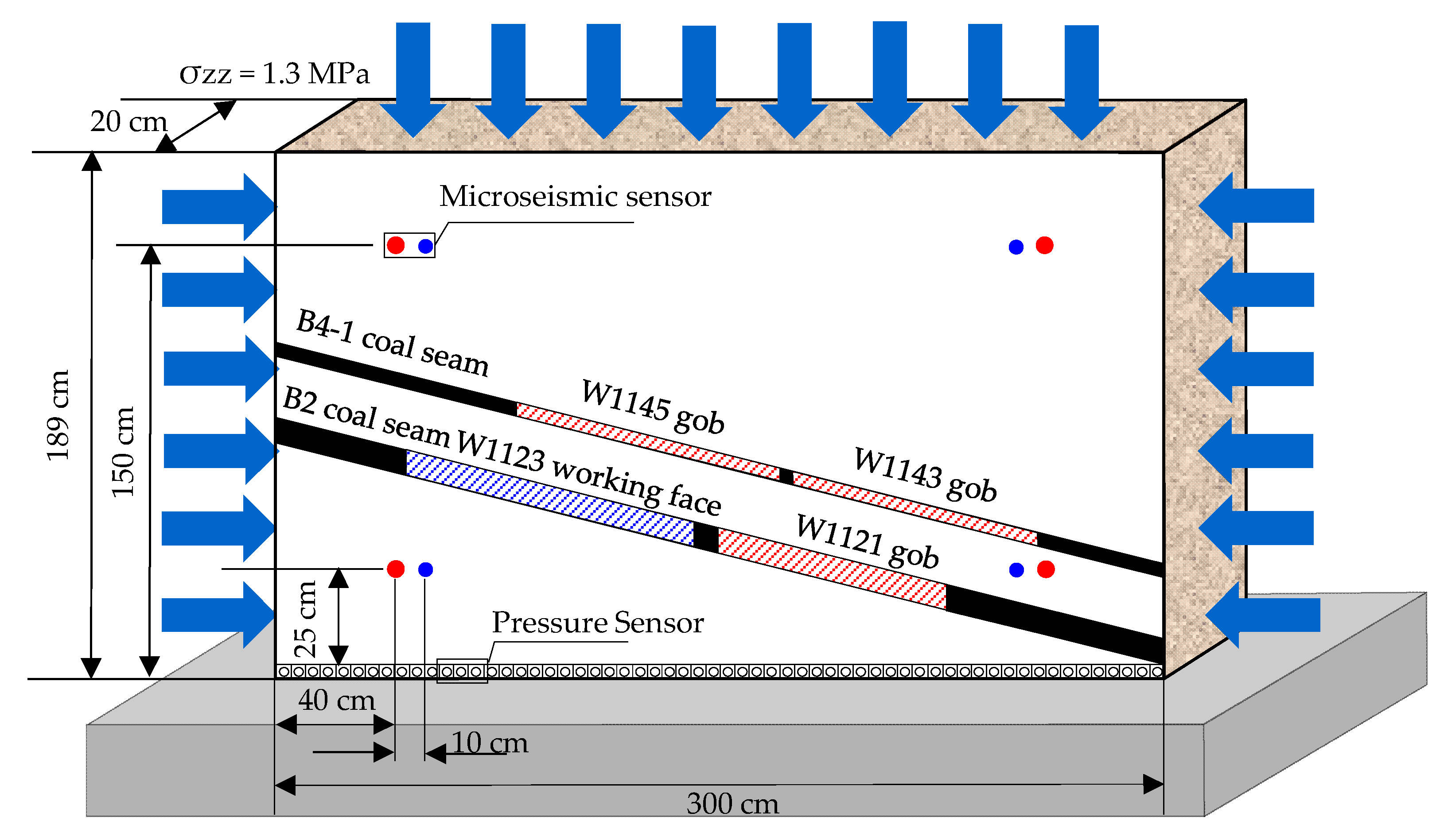
3.2. Physically Similar Material Simulation

3.2.1. Model of Similar Design

Studies have shown [19,20,21,22] that the roof of the working face tends to fracture structure, which is closely related to the microstructure of the material and the state of the section coal pillar. The method of simulating experiments using physical similar materials can well restore the roof fracture structure of the working face. Therefore, the physical similarity simulation experiment is of great significance in studying the roof fracture structure of the working face and the distribution law of the lateral supporting pressure of the working face.
Figure 7 shows the model design. Table 2 shows the mechanical parameters of rock formation. The model was built on the background of Kuangou coal mine geological conditions, using an experimental platform with an external dimension of 3.0 m × 0.2 m × 2.2 m (length × width × height), and the construction size was 3.0 m × 0.2 m × 1.89 m (length × width × height) in the experimental model. The geometric similarity ratio used in the simulation is CL = Lq/Ln = 1/200 (the subscript n represents the parameters of the prototype, and the subscript q represents the parameters of the experimental model). The unit volume density γq of the model can be measured by laboratory instruments, resulting in the gravity similarity ratio Cγ = γqn = 1/1.5, displacement similarity ratio CS = CL = 1/200, strength, elastic modulus, cohesion similarity ratio CR = CE = CC = CLCγ = 1/333, Poisson’s ratio, internal friction angle the similarity ratio is CU = Cα = 1. Due to the limited height of the experimental platform, it is necessary to apply a vertical stress of σZZ = 1.3 MPa on the top of the model to simulate the rock formation not built in the experiment. The bottom of the model is constrained to vertical displacement, and the two sides are constrained to horizontal displacement. MS sensors and floor pressure are, respectively, arranged on the surface and bottom of the model meter.
Figure 8 shows the relevant pictures of the indoor rock mechanics experiment. Table 2 lists the mechanical parameters of each rock formation. The drilling core of the overlying strata on the W1123 working face was obtained using the No. Z1201 borehole in Kuangou coal mine. Choose the following five main rock formations: sandy mudstone, coarse-grained sandstone, fine-grained sandstone, coal and mudstone. Using indoor rock mechanics experiments, the mechanical parameters of each rock formation specimen were obtained. Use fine river sand, barite powder, gypsum, mica powder and water in different mixing ratios as filling materials for each rock formation. Using the above proportion of mixed materials, a cylindrical rock specimen with a diameter of 50 mm and a height of 100 mm was prepared and tested by laboratory rock mechanics experiments. When the strength value is consistent with the theoretical calculation result, the final material mixing ratio is determined with regard to the load of the experimental model.

3.2.2. Monitoring Design

Figure 9 shows the microseismic (MS) monitoring system. Studies have shown that during the loading process of the rock, the internal micro-defects are fractured or closed, resulting in acoustic emission with very low energy level. When the rock is loaded to its failure strength, a large range of cracks will be penetrated and produced the phenomenon of acoustic emission with high energy level is called “microseismic” or MS. The experimental MS monitoring system used the SOS MS monitoring system manufactured by the Polish Mining Seismological Institute. The system is mainly composed of detector sensor, signal amplifier, signal acquisition box, data analysis and processing software, signal calibration system and display terminal. The frequency bandwidth of the detector sensor signal is 0.1–600 Hz; the sensitivity is 50–15,000 mA.s/m; the maximum sampling frequency is 2500 Hz. They cooperate with each other to form a complete system operation job.

3.2.3. Excavation Design

According to the actual mining sequence of the working face, a model excavation plan was designed. First, this was done for mine the B4–1 coal seam W1143 working face and W1145 working face. After mining the B2 coal seam W1121 working face, after the overlying strata stabilizes on the W1121 working face, mining was undertaken at the W1123 working face. First, in the W1123 working face 44 cm away from the left boundary of the model frame, the roadway with a width of 2 cm was used as the return air tunnel of this working face section, and then mining was carried out along the side of the coal seam. The W1123 working face was mined 8 times in total. The width of the secondary mining was 10 cm. The actual width of the simulated W1123 working face was 162 m. The actual width of the coal pillar between W1121 and W1123 working face was 30 m. After waiting for the overlying strata to stabilize, section coal pillar stability experiments were conducted under different widths of the working face. The roof fracture structure of the working face was observed when the working face width was 162 m, 172 m, 177 m, 182 m and 184 m, and the different working faces MS signal characteristics and pressure evolution law of floor pressure sensor under the condition of width were analyzed.

3.3. Results

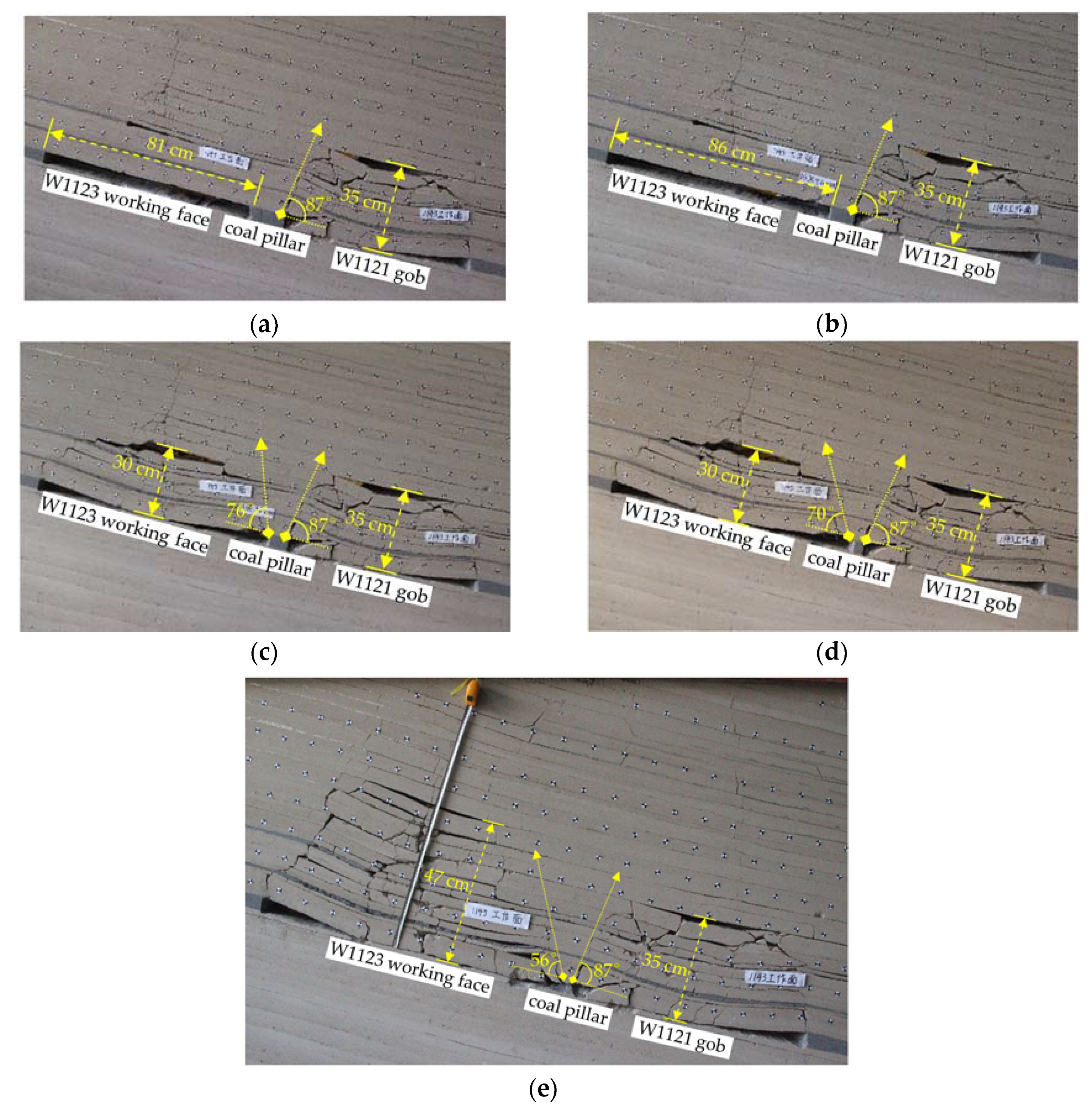
3.3.1. Roof Fracture Structure

According to the experimental results, the roof inclined fracture structure of W1123 can be divided into three main stages. Figure 10a, b depicts the first stage. It can be seen from Figure 10a that when the width of the W1123 is 162 m, the roof tilt direction of the working face is in the form of suspended rock beams, the movement of the rock formation in the W1121 mined-out area tends to be stable, the development height of the collapse zone is about 70 m, and the fracture angle of the rock formation is about 87°, the overall stability of the section coal pillar is better. As the width of the working face increases to 172 m, it can be seen from Figure 10b that the roof inclination direction of W1123 still exists in the form of suspended rock beam structure, the rock strata in the W1121 gob does not move significantly, and the section coal pillar is pulled up. Stretching fissures, the roof separation of W1123 is enlarged, and the overall stability of the coal pillar is better. Figure 10c,d depicts the second stage. It can be seen from Figure 10c that when the width of the W1123 is mined to 177 m, the suspended rock beam fractures in the middle of the W1123, and the inclined direction of the working face roof is in the form of a double-hinged structure. The development height of the collapse zone of the W1123 is about 60 m the fracture angle of the strata is about 76°, the strata in the W1121 gob does not move significantly, and the overall stability of the coal pillar in the section is good. As the width of the working face increases to 182 m, it can be seen from Figure 10 d that the inclination direction of the working face roof still exists in the form of a double-hinged structure, the rock formation in the W1121 mined-out area has not moved significantly, the rock formation in the W1123 moves downwards, and the rock formation is broken The angle is about 70°, and the section coal pillar are overall stable. Figure 10e depicts the third stage. It can be seen from Figure 10e that when the width of the W1123 is mined to 184 m, the double-hinged structure fractures, and the second turning fracture occurs in the inclined direction of the roof of the working face. At this time, the development height of the collapse zone of the W1123 is about 94 m, and the rock formation is broken. The angle is about 56°, and the coal pillar in the section is damaged due to coal pillar instability.

3.3.2. Analysis of Stress Changes

Figure 11 shows the stress distribution law of W1123 working face under different width conditions. As shown in Figure 11a, when the width of the W1123 working face is 162 m, the thick and hard roof does not break in the inclined direction of the working face, and it exists in the form of suspended rock beams. Therefore, the supporting pressure of the W1123 gob floor is relatively small, and the section coal. The column bears the load transmitted from the W1123 suspended rock beam and the W1121 mined-out area. Stress concentration occurs near the section coal column, and the maximum peak stress is 12.25 MPa. As shown in Figure 11b, when the width of the W1123 working face increases to 172 m, the thick and hard roof along the slope of the working face still exists in the form of suspended rock beams, the stress near the section coal pillar gradually increases, and the maximum peak stress reaches 13.73 MPa. As shown in Figure 11c, when the width of the W1123 working face increases to 177 m, the thick and hard roof reaches the limit fracture span in the inclined direction of the working face, and the suspended rock beam breaks to form a double-hinged structure. As the W1123 mined-out area floor is subjected to collapse because of the weight of the rock formation, the floor pressure of the W1123 mined-out area increases, and the stress near the section coal pillar decreases. The maximum peak stress is 13.45 MPa. As shown in Figure 11d, when the width of the W1123 working face is increased to 182 m, the thick and hard roof along the slope of the working face still exists in the form of a double-hinged structure, and the stress near the section coal pillar increases again, with the maximum peak stress being 13.88 MPa. As shown in Figure 11e, when the width of the W1123 working face increases to 184 m, the stress near the coal pillars in the section continues to increase, and the thick and hard roof double-hinged structure along the inclined direction of the working face breaks and loses stability, forming a multi-hinged stress arch structure. The section coal pillar was instability and destroyed, and the maximum peak stress near the section coal pillar quickly decreased to 12.25 MPa.

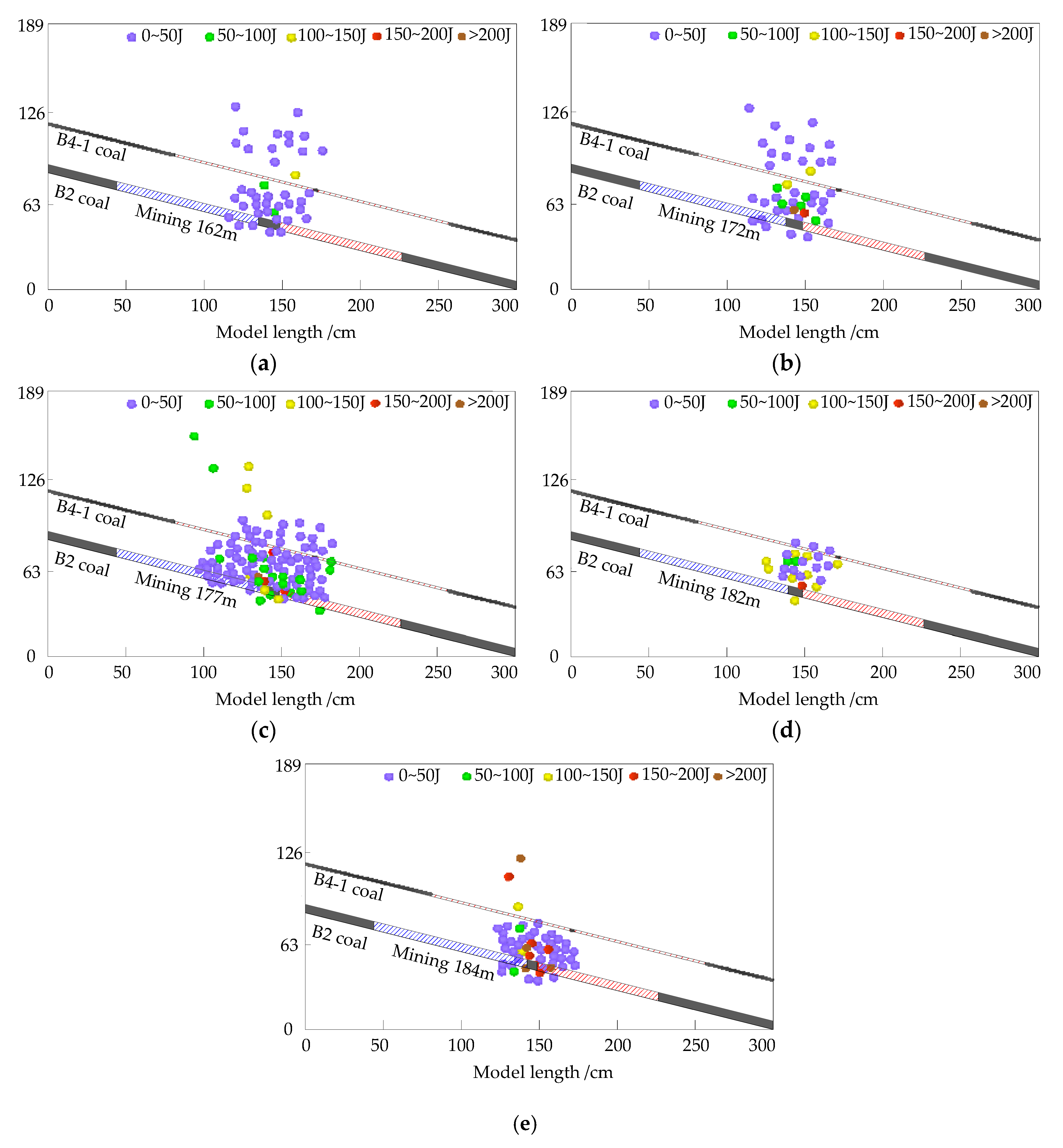
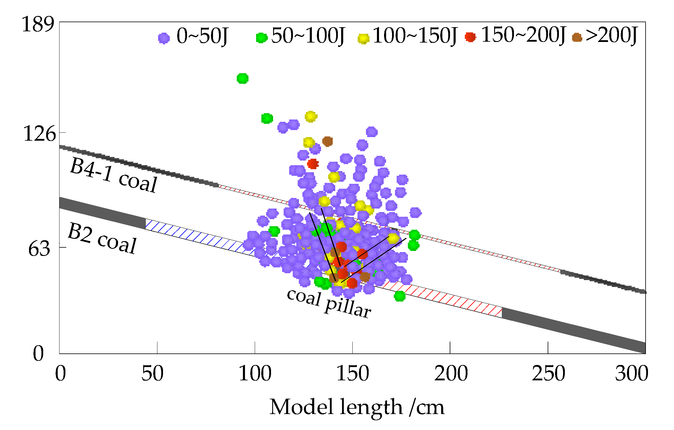
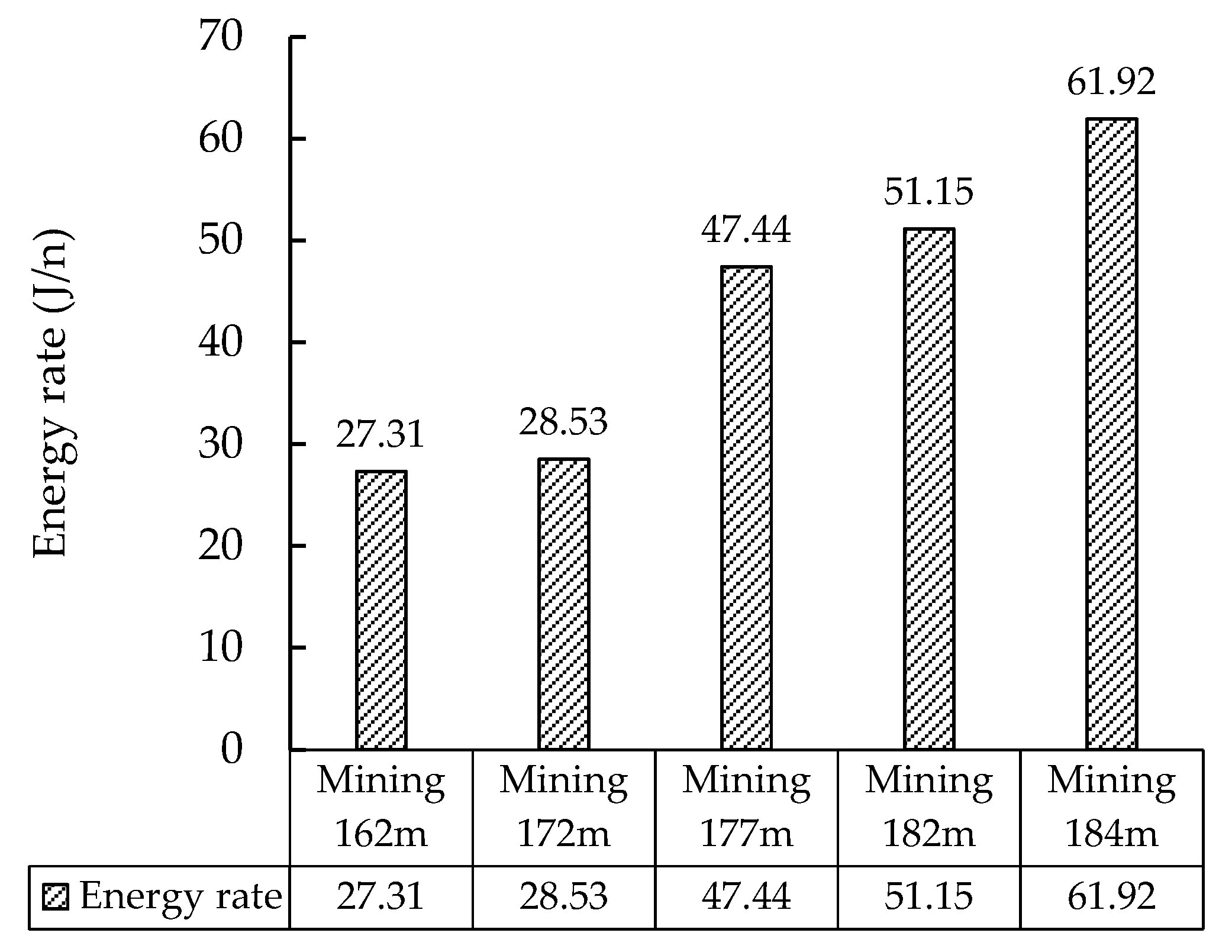
3.3.3. Analysis of MS Monitoring Results

Figure 12 shows the location of MS events under different widths of W1123 working face. As shown in Figure 12a,b, when the working face width is small, the thick and hard roof does not break obviously, there are fewer MS events, and the MS events with larger energy mostly appear in the section coal pillar stress concentration area. As shown in Figure 12c, when the width of the W1123 working face is increased to 177 m, the thick and hard roof fractures, and the elastic deformation of the thick and hard roof can be released quickly, a large number of MS events occur. As shown in Figure 12d and e, as the width of the working face further increases, MS events with greater energy frequently occur. When the width of the W1123 working face increases to 184 m, the section coal pillar suddenly suffers instability and damage, and the section coal the elastic properties of column clusters are released rapidly, MS events increase rapidly, and large-energy events occur frequently.
Figure 13 shows the distribution characteristics of MS events under different widths of the working face. It can be seen from Figure 13 that during the mining process of the working face, there are mostly MS and small energy events in the range of 0–50 J, and the small energy events mainly appear on the roof of W1123 working face and the upper coal gob. Large-energy MS events mainly appear near the section coal pillar and in the roof above the section coal pillar, in a “V”-shaped distribution state, and the energy of the MS events is mainly concentrated in the range of 100–200 J.
Figure 14 shows the proportional relationship between MS frequency and total frequency, energy and total energy under different widths of working face. It can be seen from Figure 14a that when the working face width is 162 m, the frequency of MS is 41, accounting for 17.75% of the total frequency of MS. When the working face width is 172 m, the frequency of MS is 49, accounting for the total frequency of MS. When the working face width is 177 m, the total frequency of MS events reaches the maximum of 67 times, accounting for 29% of the total frequency of MS events. This is the fracture of the thick and hard roof of the W1123 working face. The elastic energy released by the thick and hard roof is concentrated. As a result, when the working face width is 182 m, the MS frequency is 19, accounting for 8.23% of the total MS frequency. When the working face width is 184 m, the MS frequency again increases 56 times, accounting for the total frequency of MS 23.81%, which is closely related to the instability and destruction of the section coal pillar. It can be seen from Figure 14b that when the working face width is 162 m, the MS energy is 1120 J, accounting for 11.12% of the total MS energy. When the working face width is 172 m, the MS energy is 1398 J, accounting for 13.88 of the total MS energy. %, when the working face width is 177 m, the total event energy of the MS event reaches 3178.7 J, accounting for 31.55% of the total energy of the MS, when the working face width is 182 m, the MS energy is 972 J, accounting for 9.65% of the total energy of the MS When the working face width is 184 m, the total event energy of MS events reaches the maximum value of 3406 J, accounting for 33.81% of the total frequency of MS events.
The total frequency of MS events can reflect the development degree of cracks in the thick and hard roof under different widths of the working face, and indirectly reflect the tendency of the working face to fracture. The total event energy of micro-earthquakes can reflect the elastic energy release law of the thick and hard roof, but the stability of the overburden of the working face and the section coal pillar is not only related to the location and amount of energy release, but also closely related to the energy release speed, The energy release rate is expressed by the following formula:
Er = E/N
In the formula, Er is the MS energy rate, J/n; E is the total energy of MS events during the mining process of each face, J; N is the total frequency of MS events during the mining process of each face, n.
Figure 15 shows the energy release rate during mining with different widths of working face. Based on the analysis of Figure 14a,b, it can be seen that when the working face width is 162 m, the frequency of MS events and the MS energy are both at a low level, and the MS energy rate is 27.31 J/n, reflecting the stability of the overburden of the working face and the section coal pillar at this time. When the working face width is increased to 172 m, the frequency of MS events and the MS energy both increase, and the MS energy rate is 28.53 J/n, which reflects the development of cracks in the roof of the working face at this time; when the working face width increases to 177 m. At that time, the frequency of MS events and MS energy increased at the same time, and the MS energy rate was 47.44 J/n. This is the result of the accumulation of elastic energy released by the thick and hard roof fracture of the working face at this time, combined with the frequency of MS events and the increase of MS energy, It can be seen that the elastic energy release rate of the thick and hard roof of the working face is relatively slow at this time, which is beneficial to the maintenance of the overburden strata and the stability of the section coal pillar; when the working face width is 182 m, the frequency of MS events and MS events changes. Although the energy is low, the MS energy rate reaches 51.15 J/n, reflecting the frequent occurrence of MS and high-energy events, which is not conducive to the maintenance of the overburden of the working face and the stability of the section coal pillar; when the working face width is 184 m, the MS changes. Although the event frequency and MS energy are both high, the MS energy rate reaches 61.92 J/n, reflecting the frequent occurrence of MS large-energy events, which is consistent with the results of the instability and destruction of the section coal pillar at this time releasing the accumulated elastic energy.
In summary, under the conditions of different widths of W1123 working face, the fracture structure of the thick and hard roof along the inclined direction of the working face is different, and the load on the section coal pillar is also different. Combined with the geological conditions and mining technical conditions of the W1123 working face, the width of the working face is considered When it is 177 m, it is more conducive to section stability.

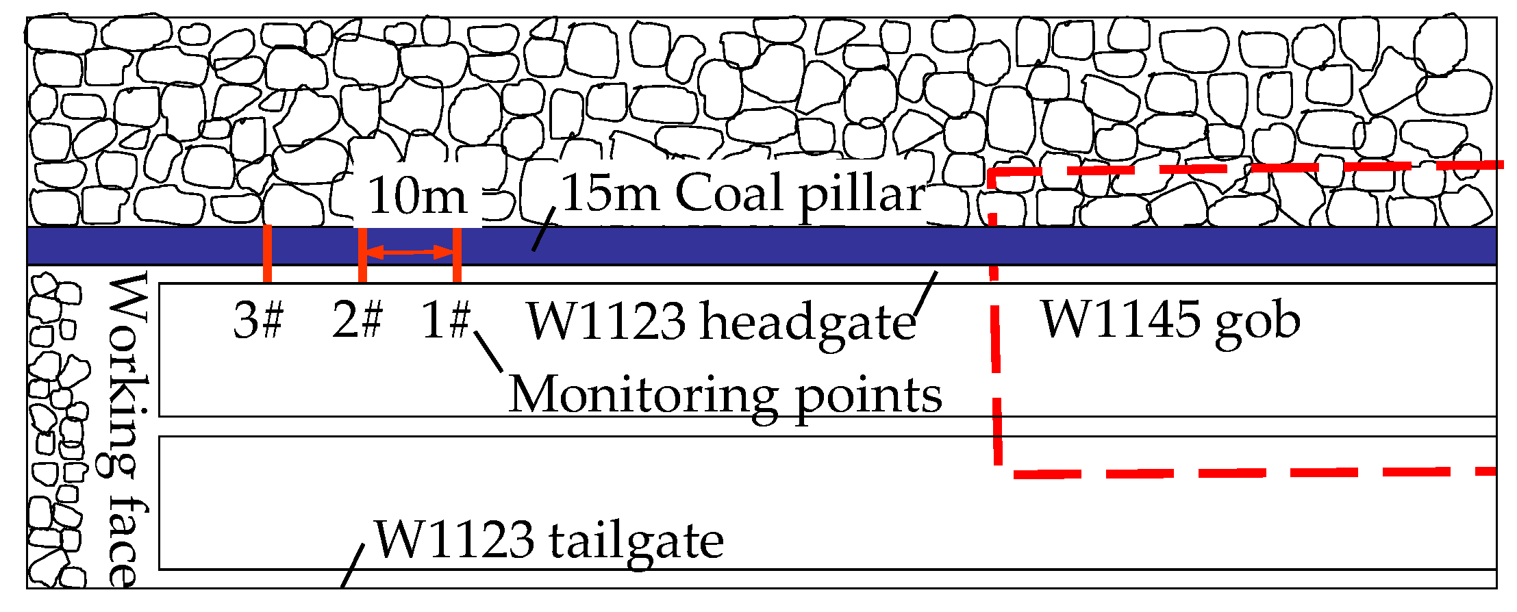
4. On-Site Monitoring

4.1. Engineering Practice Conditions

Using the above method, the reasonable width of the working face is determined to be 177 m, and then the coal pillar width of the working face section and the location of the mining roadway are determined. The W1123 working face return airway and transportation roadway adopt the arc arch section, the section size of the return airway is 4.7 m × 3.7 m (width × height), the cross-sectional area is 15.60 m2; the transportation roadway section size is 4.7 m × 3.4 m (width × height), and the cross-sectional area is 14.19 m2.
Figure 16 shows the W1123 mining roadway support plan. Seven bolts are driven into the roof of W1123 roadway. The bolt parameters are Φ0.018 × L2.5 m (diameter × length), and the row spacing between the bolts is 0.8 × 0.8 m. CK2350 resin anchoring agent is used for anchoring. Each anchor rod uses two bolts. At 1.2 m from the center line of the roadway, on the left and right sides of the roof, one anchor cable is driven. The anchor cable parameter is Φ0.0189 × L10.5 m (diameter × length), the distance between rows is 2.4 × 2.4 m, the CK2350 resin anchoring agent is used for anchoring, and each anchor cable uses three of these. Two bolts are driven on both sides of the empty roadway at the W1123 working face, with a row spacing of 0.8×0.8 m between the bolts, and drive a bottom plate bolt at a distance of 0.447 m from the bottom plate. The inclination angle is 15°. Anchor nets are hung on the roof and two sides of the roadway and reinforced with steel belts. The anchor nets use 4# cold drawn wire mesh with a width of 1 m; the steel belt parameter is processed by round steel with Φ0.012 m, and the row spacing is 0.8 m.

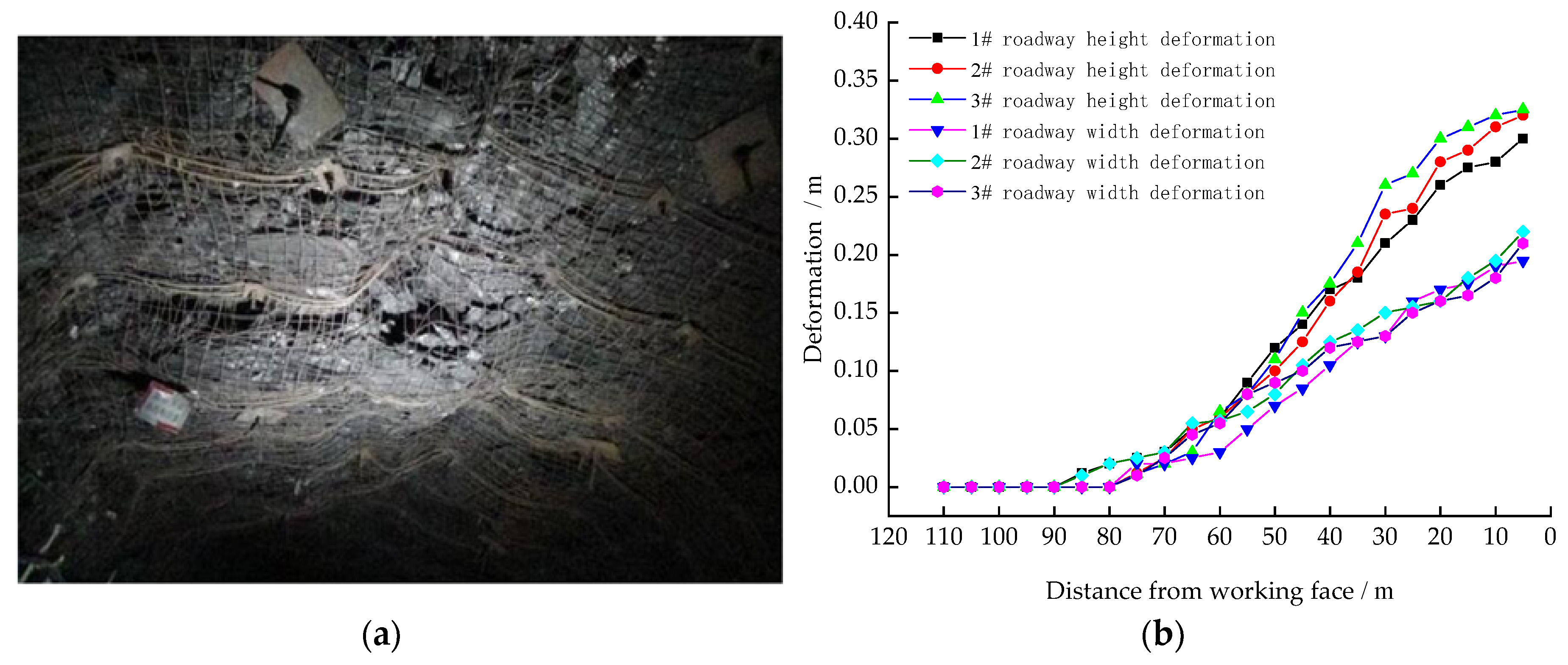
4.2. Engineering Monitoring Effect

4.2.1. Monitoring Plan

Figure 17 shows the layout of coal pillar stability monitoring in the working face section. In order to verify the stability of the coal pillars in the W1123 working face, the “cross point method” was used to monitor the surface displacement of the roadway along the gob during the mining period. The specific method is to arrange three monitoring points numbered 3#, 2#, 1# within the range of 0–110 m in front of the W1123 working face to monitor the roof and floor of the gob roadway and the approaching amount of the two sides during the mining of the working face.

4.2.2. Monitoring Results

The monitoring results shown in Figure 18a show that the overall stability of the roadway surrounding rock during the mining of W1123 working face is favorable. The monitoring result shown in Figure 18b shows that it is located in the area 80–110 m in front of the work face, the moving distance of the top and bottom plates is 0–0.023 m, the moving distance of the two banks is 0–0.02 m, and it is located in the area 30–80 m in front of the work face. The moving distance of the top and bottom plates is 0.023–0.15 m, the moving distance of the two banks is 0.02–0.257 m. When it is located in the area of 5–30 m in front of the work, the moving distance of the top and bottom plates is 0.15–0.014 m, the moving distance of the two banks It is 0.257–0.325 m. Engineering practice shows that the deformation of the surrounding rock of the roadway is within the controllable range.

5. Conclusions

Using the method of mechanical model analysis, the fracture structure of the thick and hard roof along the inclined direction of the working face and the force characteristics of the section coal pillar under different widths of the working face are analyzed. It is believed that when the width of the working face is short, the thick and hard roof along the inclined direction of the working face exists in the form of suspended rock beams, and the section coal pillar load is relatively large. As the width of the working face increases, the suspended rock beam breaks to form a double-hinged structure, and the section coal pillar load decreases. As the working face width increases again, the double-hinged structure breaks to form a multi-hinged structure, the bearing capacity of the thick and hard roof of the working face decreases, and the section coal pillar load increases again.
Through physical similarity simulation experiments, it was verified that the thick and hard roof tended to fracture under the conditions of different widths of the working face. Using technical means such as floor pressure sensors and micro-seismic monitoring, it was found that the thick and hard roof tended to fracture under the conditions of different fracture structures in the W1123 working face. By the stress evolution law and energy release characteristics, it was determined that when the working face width is 177 m, it is more conducive to the stability of the section coal pillar.
Engineering practice shows that when the width of W1123 working face is 177 m, the maximum deformation of the roof and floor of the mining roadway and the two sides of the mining roadway are 0.15–0.014 m and 0.257–0.325 m, respectively, which can meet the requirements of engineering practice. The overall stability of the section coal pillar is better, it is conducive to safe and efficient mining of the working face, and it provides a reference for the determination of reasonable working face width and the selection of section coal pillar width under similar conditions.

Author Contributions

F.C., X.L. and J.C. conceived and designed the experiments; S.D., C.J. and T.Z. performed the experiments and analyzed the data; F.C., S.D., C.J. and T.Z. wrote the paper. All authors have read and agreed to the published version of the manuscript.

Funding

This work is sponsored by the National Natural Science Foundation of China (No. 51874231), which is part of Shaanxi Innovation Capability Support Program (Program No. 2020KJXX-006), the Shaanxi Natural Science Fundamental Research Program Enterprise United Fund (2019JLZ-04) and New star of science and technology in Shaanxi Province. “Special Support Program” of Shaanxi Province in 2017 and Shaanxi Innovation Team Program (No. 2018TD-038) are gratefully acknowledged. The authors wish to acknowledge the financial support of the Outstanding Youth Science Fund of Xi’an University of Science and Technology (2019YQ2–16).

Acknowledgments

The author sincerely appreciates the equipment and site support provided by the Key Laboratory of Western Mines and Hazard Prevention of China Ministry of Education and Key Laboratory of Coal Resource Exploration and Comprehensive Utilization, as also the help and support provided by the Kuangou Coal Mine in the field monitoring support. Finally, the author sincerely thanks the above funds for financial support for this work.

Conflicts of Interest

The authors declare no conflict of interest.

References

  1. Qian, M.G.; Shi, P.W.; Xu, J.L. Mine Pressure and Rock Formation Control, 2nd ed.; China University of Mining and Technology Press: Xuzhou, China, 2010; pp. 268–276. [Google Scholar]
  2. Wang, J.H. Key technology for fully-mechanized top coal caving with large mining height in extra-thick coal seam. J. China Coal Soc. 2013, 38, 2089–2098. [Google Scholar]
  3. Xu, X.L.; Wei, H.; Tian, S.C. Study on influence law of coal pillar size on roof break structure and fracture development in fully mechanized working face. J. China Coal Soc. 2015, 40, 850–855. [Google Scholar]
  4. Wang, H.S.; Zhang, D.S.; Li, S.G. Rational width of narrow coal pillar based on the fracture line location of key rock B in main roof. Chin. J. Rock Mech. Eng. 2014, 31, 10–16. [Google Scholar]
  5. Zhu, D.; Wang, J.; Gong, W.; Sun, Z. Model Test and Numerical Study on Surrounding Rock Deformation and Overburden Strata Movement Law of Gob-Side Entry Retaining via Roof Cutting. Minerals 2020, 10, 458. [Google Scholar] [CrossRef]
  6. Zhang, X.Y.; Pak, R.Y.; Gao, Y.B.; Liu, C.K.; Zhang, C.; Yang, J.; He, M.C. Field experiment on directional roof presplitting for pressure relief of retained roadways. Int. J. Rock Mech. Min. Sci. 2020, 129, 134. [Google Scholar] [CrossRef]
  7. Zhang, G.C.; He, F.L.; Lai, Y.H. Reasonable width and control technique of segment coal pillar with high-intensity fully-mechanized caving mining. J. China Coal Soc. 2016, 41, 2188–2194. [Google Scholar]
  8. Cui, F.; Dong, S.; Lai, X.P.; Chen, J.Q.; Cao, J.T.; Shan, P.F. Study on Rule of Overburden Failure and Rock Burst Hazard under Repeated Mining in Fully Mechanized Top-Coal Caving Face with Hard Roof. Energies 2019, 12, 4780. [Google Scholar] [CrossRef] [Green Version]
  9. Cui, F.; Jia, C.; Lai, X.P.; Chen, J.Q. Study on evolution characteristics and stability of overlying strata structure in ascending mining of coal seams with strong shock tendency at close range. Chin. J. Rock Mech. Energies 2020, 39, 507–521. [Google Scholar]
  10. Dai, J.; Shan, P.; Zhou, Q. Study on Intelligent Identification Method of Coal Pillar Stability in Fully Mechanized Caving Face of Thick Coal Seam. Energies 2020, 13, 305. [Google Scholar] [CrossRef] [Green Version]
  11. Lai, X.P.; Dai, J.J.; Li, C. Analysis on disaster characteristics of overlying rock in steeply inclined coal seams. J. China Coal Soc. 2020, 45, 122–130. [Google Scholar]
  12. Kang, H.P.; Wu, Y.Z.; He, J. Rock bolting performance and field practice in deep roadway with rock burst. J. China Coal Soc. 2015, 40, 2225–2233. [Google Scholar]
  13. Shen, B.Y.; Duan, Y.; Luo, X.; van de Werken, M.; Bongani, D.; Chen, L.; Onur, V.; Ismet, C. Monitoring and modelling stress state near major geological structures in an underground coal mine for coal burst assessment. Int. J. Rock Mech. Min. Sci. 2020, 129, 104294. [Google Scholar] [CrossRef]
  14. Meng, F.; Wen, Z.; Shen, B.; Jiang, Y.; Shi, S.; Zhao, R. Applicability of Yielding–Resisting Sand Column and Three-Dimensional Coordination Support in Stopes. Materials 2019, 12, 2635. [Google Scholar] [CrossRef] [PubMed] [Green Version]
  15. Yin, S.F.; Cheng, G.Y.; He, F.L. An asymmetric support technique for fully-mechanized coal roadway nearby narrow pillar based on the fracture position analysis in basic roof. Chin. J. Rock Mech. Eng. 2016, 35, 3162–3174. [Google Scholar]
  16. Zha, W.H.; Li, X.; Hua, X.Z. Impact and application on narrow coal pillar for roadway protecting from fracture position of upper roof. J. China Coal Soc. 2014, 39, 2225–2233. [Google Scholar]
  17. Wang, Z.Q.; Guo, L.; Su, Z.H. Layout and combined support technology of alternate exterior stagger arrangement roadway and adjacent roadways in inclined and medium-thick coal seam. J. China Coal Soc. 2020, 45, 542–555. [Google Scholar]
  18. Wang, Z.T.; Qian, M.G. The calculating method of the first weighting span of main roof. J. China U Min. Technol. 1989, 2, 9–18. [Google Scholar]
  19. Sakanoi, R.; Shimazaki, T.; Xu, J.; Higuchi, Y.; Ozawa, N.; Sato, K.; Hashida, T.; Kubo, M. Communication: Different behavior of Young’s modulus and fracture strength of CeO2: Density functional theory calculations. J. Chem. Phys. 2014, 140, 121102. [Google Scholar] [CrossRef]
  20. LLawe, N.V.; Zimmerman, J.A.; Wong, B.M. Breaking Badly: DFT-D2 Gives Sizeable Errors for Tensile Strengths in Palladium-Hydride Solids. J. Chem. Theory Comput. 2015, 11, 5426–5435. [Google Scholar]
  21. Cui, F.; Yang, Y.; Lai, X.; Jia, C.; Shan, P. Experimental Study on the Effect of Advancing Speed and Stoping Time on the Energy Release of Overburden in an Upward Mining Coal Working Face with a Hard Roof. Sustainability 2019, 12, 37. [Google Scholar] [CrossRef] [Green Version]
  22. Cui, F.; Zhang, T.; Lai, X.; Cao, J.; Shan, P. Study on the Evolution Law of Overburden Breaking Angle under Repeated Mining and the Application of Roof Pressure Relief. Energies 2019, 12, 4513. [Google Scholar] [CrossRef] [Green Version]
Publisher’s Note: MDPI stays neutral with regard to jurisdictional claims in published maps and institutional affiliations.
Figure 1. Inclined fracture structure of thick and hard roof in working face. (a) Rock beam—multi articulated stress arch structure; (b) double articulated-multi articulated stress arch structure; (c) multi-articulated stress arch—multi articulated stress arch structure.
Energies 13 05344 g001
Figure 2. Geological model of coal pillar load.
Energies 13 05344 g002
Figure 3. Roof inclined fracture structure of short width working face. (a) Mechanical model of rock beam multi-articulated structure; (b) rock beam structure isolator; (c) multi-articulated structure isolator.
Energies 13 05344 g003
Figure 4. Roof inclined fracture structure of medium width working face. (a) Mechanical model of double-articulated–multi-articulated structure; (b) double-articulated left end structural isolator; (c) double-articulated right end structural isolator.
Energies 13 05344 g004
Figure 5. Roof inclined fracture structure of long width working face. (a) Mechanical model of multi-articulated–multi-articulated structure; (b) multi-articulated left end structural isolator; (c) multi-articulated right end structural isolator.
Energies 13 05344 g005
Figure 6. (a) Geographical overview; (b) W1123 working face layout; (c) roof and floor lithology.
Energies 13 05344 g006
Figure 7. Model design.
Energies 13 05344 g007
Figure 8. The mechanical test.
Energies 13 05344 g008
Figure 9. Microseismic (MS) monitoring system.
Energies 13 05344 g009
Figure 10. Roof inclined fracture structure of working face with different width. (a) Mining 162 m; (b) mining 172 m; (c) mining 177 m; (d) mining 182 m; (e) mining 184 m.
Energies 13 05344 g010
Figure 11. Stress distribution in working face with different width. (a) Mining 162 m; (b) mining 172 m; (c) mining 177 m; (d) mining 182 m; (e) mining 184 m.
Energies 13 05344 g011
Figure 12. Location of MS events on working faces with different widths. (a) Mining 162 m; (b) mining 172 m; (c) mining 177 m; (d) mining 182 m; (e) mining 184 m.
Energies 13 05344 g012
Figure 13. Distribution characteristics of MS events.
Energies 13 05344 g013
Figure 14. MS frequency and energy. (a) Frequency ratio of MS under different working face width; (b) MS energy ratio under different working face width conditions.
Energies 13 05344 g014
Figure 15. MS energy release rate.
Energies 13 05344 g015
Figure 16. Roadway support design section drawing.
Energies 13 05344 g016
Figure 17. Roadway stability monitoring.
Energies 13 05344 g017
Figure 18. Engineering practice monitoring results. (a) Deformation monitoring of transportation lanes; (b) stability monitoring curve of transportation roadway.
Energies 13 05344 g018
Table 1. Sectional coal pillar stability under different structural conditions.
Working Face WidthRoof StructureCoal Pillar Load
shortrock beam 1 2 γ H cos α 2 ( L 1 + L 2 ) + 1 2 γ H 1 2 cos α ( cot δ 1 + cot δ 2 ) + B γ H 2 cos α
mediumdouble articulated 1 2 γ H cos α ( L 2 cos α + L 3 cos β + L 4 cos α ) + 1 2 γ H 1 2 cos α ( cot δ 1 + cot δ 2 ) + B γ H 2 cos α
lengthmulti articulated 1 2 γ H cos α 2 ( L 5 + L 2 ) + 1 2 γ H 1 2 cos α ( cot δ 1 + cot δ 2 ) + B γ H 2 cos α
Table 2. Mechanical parameters.
NO.LithologyUnit Weight/(kN/m3)Tensile Strength (MPa)Bulk Modulus (GPa)Shear Modulus
(GPa)
Cohesion
(GPa)
Internal Friction Angle (°)
1Sandy mudstone25465.168.124.412.6230.4
2Coarse sandstone25417.4813.4510.944.4829.7
3Fine sandstone26318.4619.5714.073.1728.3
4coal15762.031.470.661.6829.1
5Mudstone24673.177.423.832.2831.7

