Article

Effects of Reservoir Parameters on Separation Behaviors of the Spiral Separator for Purifying Natural Gas Hydrate

1
Chinesisch Deutsch Hsch Angew Wissensch, Yibin University, Yibin 644000, China
2
Department of Mechatronic Engineering, Southwest Petroleum University, Chengdu 610500, China
*
Authors to whom correspondence should be addressed.
Energies 2020, 13(20), 5346; https://doi.org/10.3390/en13205346
Submission received: 3 August 2020 / Revised: 17 September 2020 / Accepted: 7 October 2020 / Published: 14 October 2020

Abstract

:
The spiral separator is an important tool for desanding in natural gas hydrate production, and the change of hydrate reservoir parameters has a great impact on spiral separator behavior. Mastering the influence law is helpful to improve the separation performance. Until now, there was still no detailed analysis of the effect mechanism between reservoir parameters and spiral separator behavior. In this paper, a downhole spiral separator was designed. Then, the effects of reservoir parameters (particle size, hydrate, volume fraction, and sand volume fraction) on separation performance (discrete phase distribution, separation efficiency, and differential pressure) with different flow rates were investigated by numerical simulation method Fluent 18.0. The results show that effects degree of reservoir parameters is in order from large to small: sand phase volume fraction, particle size, hydrate volume fraction. As the particle size increases, the separation performance is improved. When the sand volume fraction increases, the natural gas hydrate (NGH) recovery efficiency and differential pressure both increase, but the sand removal efficiency decreases. When the hydrate fraction increases, the separation performance change law is opposite to that when the sand volume fraction increases. In addition, with increasing the flow rate, the efficiency and differential pressure increase. Therefore, reservoir saturation and porosity can balance NGH recovery efficiency and sand removal efficiency. Furthermore, the spiral separator has good performance under the change of reservoir parameters. The performance of the NGH spiral separator can be also maintained by increasing the flow rate.

1. Introduction

Natural gas hydrate (NGH is the acronym of natural gas hydrate, which is the symbol of natural gas hydrate in this paper) is considered as a potential clean alternative energy resource. It is reported that the total amount of methane gas varies from 2.8 × 10¹⁵ to 3 × 10¹⁸ m3 in the global gas hydrate resources [1,2]. The general perception of total carbon content in natural gas hydrate is more than twice that of all conventional fossil fuels. Therefore, its production is an important strategic area to achieve sustainable energy development.
Natural gas hydrate occurs under conditions of high pressure and low temperature which exist in the deep oceanic sediments or the permafrost regions sediments [3,4]. Most of it is non-diagenetic natural gas hydrate in the deep oceanic sediments, which have characteristics of shallow burial, no dense caprock, non-diagenesis, weak cementation, large sand concentration, and variable reservoir parameters (saturation, porosity, and particle size). Therefore, there is a large amount of sand production in the process of marine hydrate exploitation [5,6,7]. Specifically, the depressurization testing productions are almost directly or indirectly terminated due to a large amount of sand production—for example, testing production in Japan in 2013 and 2017 in Aichi Omei Peninsula and Shimo Peninsula in Sanshuo Prefecture [8,9]. Because its main sand control method is the expansion of traditional mechanical sand control, its sand control capability is deficient [10,11]. Another method is “solid fluidization” which achieved good performance in South China Sea test production [12,13]. As shown in Figure 1, the sand control technology of this method is in-situ real-time sand removal and purification backfilling for crushed hydrate mixture slurry, which reduces the energy consumption of pipeline pumping, and prevents pipeline plugging. Moreover, it is less likely to break the pressure and temperature equilibrium state of NGH reservoir, and the production efficiency of the NGH is improved. The separation device is the essential and key equipment of in-situ real-time separation backfill system. However, due to the wide distribution types of hydrate, the reservoir parameters are variable, and the change of hydrate reservoir parameters has a great impact on separation device behavior. Therefore, mastering the influence of law is helpful to improve the separation performance.
As conventional swirling separation equipment, the hydrocyclone and spiral separator have been widely used in industry, because it has the advantages of simple structure, small floor area, high separation efficiency, and large processing capacity, etc. The above factors indicate that the swirling separation technology has great potential in the removal of sand from the hydrate mixture slurry. The desanding hydrocyclone and spiral tube separator used for purifying NGHs were designed, but they are devices on land, and their treated particle diameters were millimeter-scale [14,15,16]. The hydrocyclone was also applied to downhole oil–water or gas–liquid separation, but its capacity is small [17,18]. Xu Baorui [19], Ji, Yipeng [20], Lixin Zhao et al. [21,22] who analyzed the flow field in the spiral separator. They obtained that the maximum pressure loss under specific conditions was not more than 90 kPa and applied it to oil–water separation. Wang Qingwei et al. [23,24] carried out the design theory and flow field analysis of downhole gas–liquid separator spiral separator, providing certain theoretical guidance for the design of downhole gas–liquid separator. Prashant Dixit [25] employed three factors in a three-level Box–Behnken design of experiments coupled with response surface methodology to optimize the performance of fine mineral spiral separator for separation of pre-concentrated iron ore slime. The performance of the optimized separator is greatly improved. M.A. Doheim [26] simulated the particle flow in a spiral separator and obtained the velocity characteristics of the particle flow. However, there is no report on the related research of the effects of reservoir parameters on separation performance. Thus, a detailed analysis with respect to the reservoirs parameter will fetch a better understanding of the separation properties and lay a foundation for improving NGH spiral separator performance.
In this work, a spiral separator was designed as a downhole desanding device for purifying natural gas hydrate. Then, the effects of reservoir parameters on separation performance with different flow rates were investigated by numerical simulation method Fluent 18.0. In detail, the NGH recovery efficiency, sand removal efficiency, differential pressure, NGH phase distribution, and sand phase distribution of the spiral separator were investigated by CFD-Fluent at inlet velocity of 2 to 6 m/s, inlet NGH volume fraction of 5% to 25%, inlet sand volume fraction of 5% to 25%, and particle diameter of 2 to 100 μm.

2. Materials and Methods

2.1. The Structure of the Downhole Spiral Separator

Figure 2 presents the designed two-stage modular parallel downhole spiral separator structure, which is mainly divided into five parts: bottom joint, middle joint, top joint, modular spiral separator tube, and outer tube. The bottom joint connects the nozzle and modular parallel downhole spiral separator. The middle joint connects the modular spiral separator tube in the modular parallel downhole spiral separator. The top joint connects the modular parallel downhole spiral separator and the double-layer pipe. The connection mode is modular, which makes the connection convenient and fast. Therefore, in the finite downhole radial space, the processing capacity of the separator system is bigger than the traditional type. Figure 3 shows fluid flow direction. The red arrow is downward flow direction of water or drilling fluid injected from the vessel, which provides power for bit drilling and nozzle breaking hydrate reservoir. The black arrow is the flow direction of crushed gas hydrate mixture slurry, the yellow arrow is the flow direction of purified gas hydrate slurry, and the blue arrow is the flow direction of sand slurry. Mixed gas hydrate slurry enters the inlet of each separator at one time, and then purified and separated through the separator. The purified gas hydrate enters the hydrate recovery port at one time, and is finally piped to the vessel. The sand slurry enters the sand removal outlet to discharge and fill back. The sand backfilling can effectively prevent reservoir collapse.

2.2. CFD Numerical Simulation

The structure of spiral separator was simplified, and it is shown in Figure 4a. The structural parameters are shown in Table 1.

2.2.1. Mesh and Model Description

The 3D computational model was selected in this paper, and the grid at the central section of the 3D model is shown in Figure 4b. The whole computational domain was represented by unstructured grids, which are also tetrahedra. In total, about 250,000 cells were used in the present work. In order to reflect the movement of multiphase flow more truly, the grids of key parts such as the inlet and outlet were refined to varying degrees.
Because of the mixture model with characteristics of both the calculation precision and speed, the mixture model was used in the multiphase flow model. The Reynolds stress model (RSM) is more time-consuming compared to the Reynolds-averaged Navier–Stokes (RANS) model, but it is time-saving compared to the large eddy simulation (LES) model. The RSM also has great potential to predict behavior of complex flows such as swirling flow through the separator accurately. The RSM model involves calculation of the individual component of turbulence stress tensor using the partial differential transport equation. Therefore, the Reynolds stress model, which is reported to predict turbulence behavior inside a spiral separator with a higher accuracy in [19,25], was used.
The continuity equation is as follows [19,25]:
ρ t + ρ u i x i = 0
The momentum equation of the mixture model is as follows [19,25]:
t ρ u i + x j ρ u i u j = x i p + x i k = 3 n p k + x j μ u i x j + u j x i + ρ u i u j ¯ + k = 1 n ρ k u d r , k i u d r , k j + g ρ
where u d r is the drift velocity, g is gravitational acceleration, and ρ u i u j ¯ is the Reynolds stress term. Where u j , u i and ρ are velocity and the density of the mixture phase fluid, respectively, which are defined as equations [25]:
ρ = k = 1 n α k ρ k ,   u i = k = 1 n α k ρ k u k , i ρ , μ = k = 1 n α k μ k
where μ k , α k , ρ k , and u k are viscosity, the volume fraction, density, and velocity of the kth phase fluid, respectively.
The RSM model transport equation is defined as [25]:
ρ u i u j ¯ t + ρ u k u i u j ¯ x k = D T , i j + D L , i j + P i j + G i j + Φ i j + ε i j + F i j
where D L , i j is molecular viscous diffusion, D T , i j is the turbulent diffusion, G i j is the buoyancy generation, Φ i j is the pressure strain, ε i j is viscous dissipation, F i j is the system rotation generation, and P i j is shear stress generation.

2.2.2. Boundary Conditions

It was assumed that there was no phase change during the whole separation process because it almost did not change the temperature and pressure of gas hydrate in situ and real-time separation. So, all NGH was assumed to be solid, and the NGH particle diameter was the same as that of sand particles. Natural gas hydrate reservoir parameters are mainly sediment particle size, porosity, and saturation. In the separation process, the above parameters are embodied in the particle size, the inlet hydrate phase, and the sand phase volume fraction in the mixed slurry. According to the analysis results of particle size distribution of marine gas hydrate sediments in the South China Sea, the distribution plot of sediment particle diameter which was measured by a BT-9300LD dry wet laser particle size analyzer is shown in Figure 5. The particle diameter of sediment is mainly less than 100 μm, most of which is about 30 μm. Therefore, in this paper, the particle diameter ranged from 2 to 100 μm (characteristic particle sizes of 2, 20, 40, 60, 80, and 100 μm), when the volume fraction of hydrate and sand were 10% and 15%, respectively. When the particle diameter was 30 μm, the volume fraction of hydrate and sand was set in the range of 5% to 25%, and inlet velocity ranged from 2 to 6 m/s. The physical parameters used in this paper are shown in Table 2.
In this paper, ANSYS Fluent 18.0 software (Canonsburg, USA) was used for numerical simulation in Chengdu, China. Furthermore, simulation was carried out in a 3D model, with steady state, double precision implicit solver adopted. The SIMPLE algorithm scheme, which uses a combination of continuity and momentum equations to derive an equation for pressure, was used. The QUICK spatial discretization scheme was applied, as it is reported to be useful for swirling flows. Inlet condition was velocity inlet. Outlet was pressure outlet, and the no-slip boundary condition was used for the wall boundary.

3. Results and Discussion

3.1. Model Validation and Grid Independency

The radial coordinates of measuring points were characterized by dimension-one radial position r* = 2 r/D, r* = 0 represented the central position of cross section, and r* = 1 and r* = −1 represented the top and bottom positions of inner walls of circular tubes, respectively. The comparison of radial, axial, and tangential velocity distribution curves in the inlet section of the spiral separator obtained by PIV (Particle Image Velocimetry) test in the reference literature [19] and CFD numerical simulation is shown in Figure 6. It can be seen that for the velocity trend and distribution, the numerical simulation results are basically in agreement with the experimental results. Because the numerical model used in this paper is the same as that used in [19], it is noted that the model is validated in this paper.
There are five grids with 150,000, 200,000, 250,000, 300,000, and 350,000 selected to check the solution independency. The results of maximum static pressure are shown in Table 3. It can be seen that when the number of grids is greater than 250,000, the maximum static pressure is independent. In the rest of this research, the grid total numbers were about 250,000.

3.2. Separation Performance

As we know, the typical performance evaluation indexes of spiral separator include discrete phase distribution, separation efficiency, and pressure drop. Therefore, the relationship between reservoir parameters and the above indexes was mainly investigated.

3.2.1. Discrete Phase Distribution

Figure 7 and Figure 8 present NGH and sand distribution contours across horizontal section of spiral separator and vertical section at outlet with different particle diameter, respectively. As observed from the contours, with increasing particle diameter, NGH volume fraction increases at the center of the spiral separator and sand volume fraction increases at the wall of the spiral separator. The above phenomena are particularly obvious at the outlet. When particle diameter is more than 40 μm, most of the NGH particles are distributed in the NGH recovery outlet, most of the sand particles are distributed in the sand removal outlet. The above results show that the particle size has a great influence on the discrete phase distribution, and the increasing of particle diameter is beneficial to the recovery of NGH and removal of sand.
NGH and sand distribution were investigated across the horizontal section of the spiral separator and the vertical section at the outlet for the inlet NGH volume fractions of 5%, 10%, 15%, 20%, and 25% as shown in Figure 9 and Figure 10. According to the figures, with the increasing of inlet NGH volume fraction, the NGH volume fraction in the spiral separator increases, particularly in the sand removal outlet, and the sand volume fraction increases in the sand removal outlet. It can be explained that the boundary between NGH and sand moves towards the wall, when the inlet NGH volume fraction increases. The results reveal that the increasing of the inlet NGH volume fraction is beneficial to sand removal, but it is not for NGH recovery.
As shown in Figure 11 and Figure 12, NGH and sand distribution were investigated across the horizontal section of the spiral separator and the vertical section at the outlet for inlet sand volume fraction of 5%, 10%, 15%, 20%, and 25%. It can be seen that as an increasing of inlet sand volume fraction, the sand volume fraction in spiral separator increases, particularly in the NGH recovery outlet. At the same time, the NGH volume fraction increases in the NGH recovery outlet with the increasing inlet sand volume fraction. It can be explained that the boundary between NGH and sand phases moves towards the center of the spiral separator. The results indicate that in contrast to the increasing of the inlet NGH volume fraction, an increasing of sand volume fraction is beneficial to NGH recovery, but not conducive to the improvement of sand removal.
In general, it is also seen from the above figures that with increasing inlet velocity from 2 to 6 m/s, the NGH volume fraction increases at the center of the spiral separator, and the sand volume fraction increases at the wall of the spiral separator, especially at the outlet. The distribution of each phase is uniform in the inlet. The NGH phase volume fraction decreases along the center to the wall in the spiral section and outlet, while that in the sand phase increases. It can be explained that an increasing of inlet velocity will increase the centrifugal force and pressure gradient force to change the boundary between NGH and sand phases, causing particles to easily enter the ideal outlet.

3.2.2. Separation Efficiency

The separation efficiency is an important index of the separation performance of spiral separator. The sand discharge amount and hydrate recovery amount are considered at the outlet section in this device. Separation efficiency is generally defined as the ratio of outlet phase mass to inlet phase mass.
E 1 = M o 1 M i 1 × 100 % E 2 = M o 2 M i 2 × 100 %
where E1 is natural gas hydrate recovery efficiency %, Mo1 is natural gas hydrate mass flow rate at split outlet section (kg/s), Mi1 is natural gas hydrate mass flow rate at inlet (kg/s), E2 is sand removal efficiency %, Mo2 is sand mass flow rate at split outlet section (kg/s), and Mi2 is sand mass flow rate at inlet (kg/s).
Figure 13 shows the plots of relationship between particle diameter and separation efficiency (NGH recovery efficiency and sand removal efficiency). It is observed that with the increasing of particle diameter, the NGH recovery efficiency and sand removal efficiency increase first and then tend to be steady. This is the same trend as the above phase distribution contours. The NGH recovery efficiency and sand removal efficiency are more than 60%, when the particle diameter is greater than 20 μm. At the same particle diameter, the NGH recovery efficiency is greater than the sand removal efficiency. The cutting size of hydrate is much smaller than that of sand. On the other hand, with the increasing of inlet velocity, the NGH recovery efficiency and sand removal efficiency increase, but the cutting sizes decrease. The main reason is that when the particle diameter or inlet velocity increase, the centrifugal force for the particles increases. Consequently, the probability of NGH particles moved to the center, and sand particles moved to wall increase. Another reason is that the structure parameters of the separator outlet are fixed and the fluid diversion ratio is constant. The results demonstrate that the change of particle size has a greater impact on the performance of the spiral separator, and the NGH recovery efficiency and sand removal efficiency can be improved by increasing the inlet velocity.
The plots of relationship between the inlet NGH volume fraction and separation efficiency (the NGH recovery efficiency and sand removal efficiency) are shown in Figure 14. It can be seen that with the increasing of the inlet NGH volume fraction, the NGH recovery efficiency decreases, but the sand removal efficiency increases, which matches the distribution contours of NGH and sand. The main reason is that the density of pure NGH is less than that of seawater; increasing the inlet NGH volume fraction slightly reduces the viscosity and density of the mixed liquids. Under the same dynamic force, the sand moves more easily to the wall. At the same time, the interface between hydrate layer and sand layer moves toward the wall, and the NGH recovery and sand removal outlet remains unchanged. The above results show that the separation efficiency of the spiral separator is less affected by the change of hydrate saturation.
In Figure 15, the plots of relationship between the inlet sand volume fraction and separation efficiency (the NGH recovery and sand removal efficiency) are presented. These can be seen that when the inlet sand volume fraction increases, the NGH recovery efficiency increases, but the sand removal efficiency decreases, which is consistent with the distribution contours of NGH and sand. Because with increasing the inlet sand volume fraction, the interface between hydrate layer and sand layer moves to the center, while the NGH recovery and sand removal outlet remains unchanged. So, the proportion of NGH entering the NGH recovery pipe increases, but the proportion of sand entering the sand removal outlet decreases. The sand density is larger than that of seawater; when the inlet sand volume fraction increases, the viscosity and density of the mixed slurry increase. Therefore, the resistance of the particle migration increases, especially for sand particles. The above results show that sand saturation has a great influence on the performance of the spiral separator, and high sand saturation is helpful to NGH recovery.
On the other side, when inlet velocity increases, the NGH recovery efficiency and sand removal efficiency increase continuously. The main reasons are that the increase of inlet velocity increases the centrifugal force, so that the probability of hydrate migration to the center and sand migration to wall increase. Therefore, increasing the inlet velocity is helpful to the recovery of NGH and sand removal.

3.2.3. Differential Pressure

As we know, the low differential pressure of separator represents its low energy consumption. Thus, the differential pressure is also one of the most important indexes to evaluate the performance of separator.
The differential pressure is shown in the equation:
p 1 = p 0 p 1 p 2 = p 0 p 2
where p 1 is NGH differential pressure (Pa), p 0 is inlet pressure (Pa), p 1 is NGH recovery outlet pressure (Pa), p 2 is sand differential pressure (Pa), and p 2 is sand removal outlet pressure (Pa).
The plots of relationship between particle diameter and differential pressure are presented in Figure 16. In general, the values of differential pressure were within 6,000,000 Pa, and the lowest is as low as 500,000 Pa. When the particle diameter increases, the differential pressure increases, but the increased amplitude is small. The main reason is that the change of particle diameter has little effect on the capacity conversion in the whole separation process. In addition, the NGH differential pressure is greater than the sand differential pressure because the diameter of the hydrate recovery outlet is smaller than that of the sand removal outlet.
The plots of relationship between the inlet NGH volume fraction and the differential pressure are presented in Figure 17. It can be observed that the differential pressure decreases slightly with increasing the inlet NGH volume fraction, and the greater the inlet velocity is, the more obvious the decrease trend is. The main factor causing the above results is that the density of NGH is less than that of seawater, and its value is close to seawater. Increasing of the inlet NGH volume fraction slightly reduces the viscosity and density of the mixed liquids, which helps to reduce friction loss. The results reveal that the change of hydrate saturation has little effect on differential pressure of the NGH downhole spiral separator.
Figure 18 shows the plots of relationship between the inlet sand volume fraction and the differential pressure. When the inlet sand volume fraction increases, the differential pressure increases continuously, and the larger the inlet velocity, the greater the increased amplitude is. It can be explained that the sand density is larger than that of seawater, when the inlet sand volume fraction increases, the viscosity and density of the mixed slurry increase. Therefore, the friction loss increases sharply in the spiral separator. It is shown that the variation of sand saturation has great influence on the differential pressure of the spiral separator. Even so, it also shows that the spiral separator can be adapted to NGH reservoirs with different sand saturation.
On the other hand, with the increasing of inlet velocity, differential pressure increases sharply, especially when the inlet velocity exceeds 4 m/s. When the inlet velocity is larger, the larger the amplitude of differential pressure increases. The main reason is that increasing inlet velocity will increase the turbulence of flow field, friction loss, and local energy loss, and there is more static pressure energy converted into velocity energy. It indicates that the inlet velocity has a great influence on the differential pressure of the NGH downhole spiral separator. Therefore, in order to reduce energy consumption, lower inlet velocity should be adopted within the allowable range.

4. Conclusions

(1)
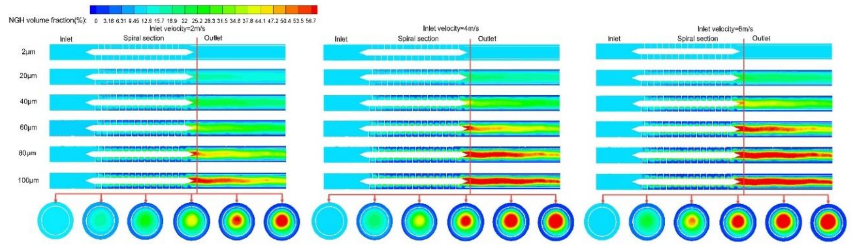
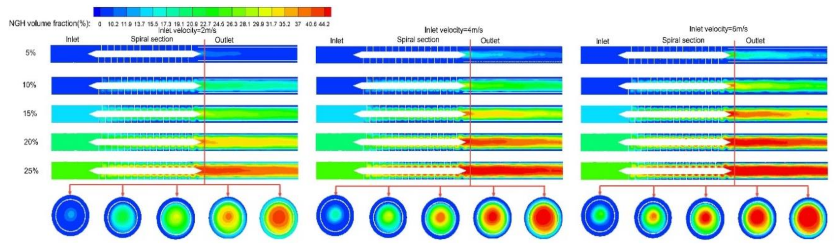
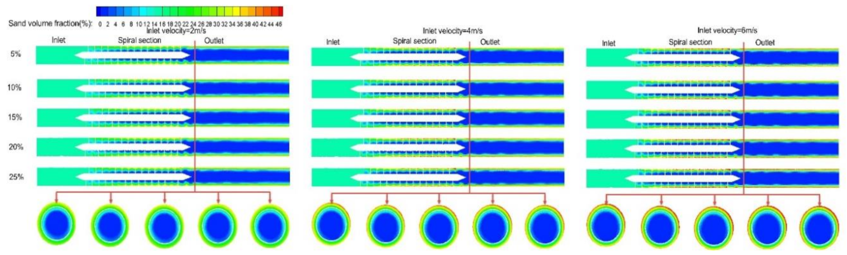
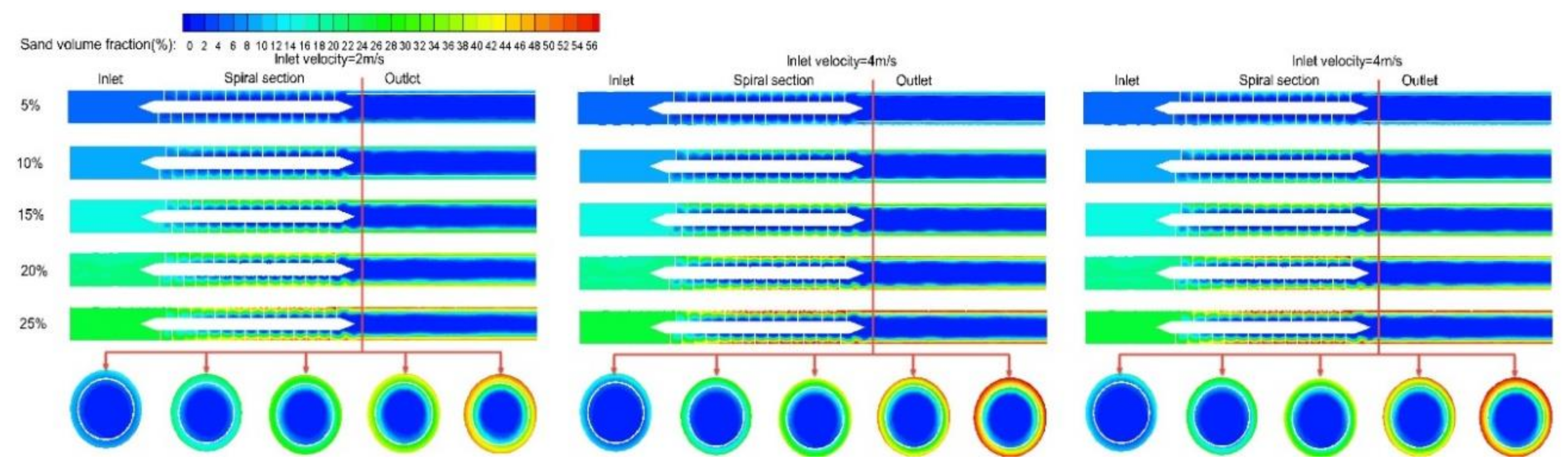
The distribution of each phase is uniform in the inlet, and the NGH phase volume fraction decreases along the center to the wall in the spiral section and outlet while that in the sand phase increases. With increasing particle diameter and inlet sand volume fraction, the NGH volume fraction increases at the center of the spiral separator, and the sand volume fraction increases at the wall of the spiral separator. It shows that the spiral separator shows good performance in the recovery of NGH and sand removal.
(2)
The NGH recovery efficiency and sand removal efficiency increase first and then tend to be steady. With the increasing of the inlet sand volume fraction, the NGH recovery efficiency increases, but the sand removal efficiency decreases. When the inlet NGH volume fraction increases, the separation efficiency change law is opposite to that when the inlet sand volume fraction increases.
(3)
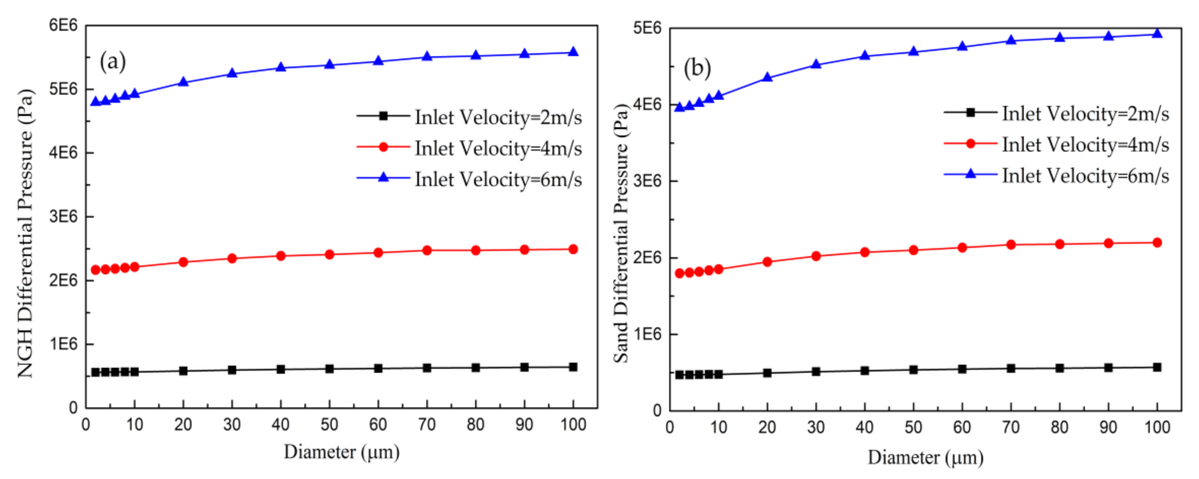
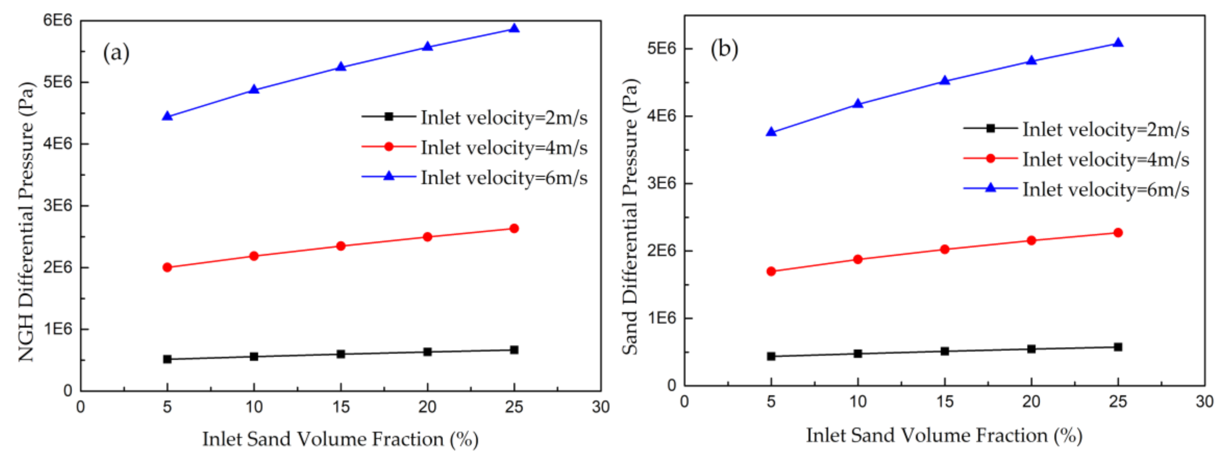
The differential pressure increases when the particle diameter and inlet sand volume fraction increase, whereas it decreases with increasing of the inlet NGH volume fraction. Therefore, the saturation and porosity of hydrate reservoir are one of the decisive factors of energy loss of the spiral separator.
(4)
Effects degree of reservoir parameters is in order from large to small: sand phase volume fraction, particle size, and hydrate volume fraction. The results show that the reservoir saturation and porosity can balance NGH recovery efficiency and sand removal efficiency. Furthermore, the spiral separator has good performance under the change of reservoir parameters. When inlet velocity increases, the NGH recovery efficiency, sand removal efficiency, and differential pressure increase continuously. Therefore, increasing the inlet velocity is helpful to improve separation performance.

Author Contributions

Conceptualization, G.W. and S.Q.; methodology, G.W.; validation, S.Q.; formal analysis, S.Q.; investigation, S.Q.; resources, S.Q.; data curation, S.Q.; writing—original draft preparation, S.Q.; supervision, G.W.; project administration, G.W.; funding acquisition, G.W. All authors have read and agreed to the published version of the manuscript.

Funding

National Key R&D Program of China, grant number [2018YFC0310201].

Acknowledgments

The authors are grateful to the National Key R&D Program of China [2018YFC0310201] for the financial support of this work.

Conflicts of Interest

The authors declare no conflict of interest.

References

  1. Kezirian, M.T.; Phoenix, S.L. Natural Gas Hydrate as a Storage Mechanism for Safe, Sustainable and Economical Production from Offshore Petroleum Reserves. Energies 2017, 10, 828. [Google Scholar] [CrossRef] [Green Version]
  2. Boswell, R.; Collett, T.S. Current perspectives on gas hydrate resources. Energy Environ. Sci. 2011, 4, 1206–1215. [Google Scholar] [CrossRef]
  3. Chong, Z.R.; Yang, S.H.B.; Babu, P.; Linga, P.; Li, X.-S. Review of natural gas hydrates as an energy resource: Prospects and challenges. Appl. Energy 2016, 162, 1633–1652. [Google Scholar] [CrossRef]
  4. Collett, T.S.; Johnson, A.H.; Knapp, C.C.; Boswell, R. Natural gas hydrates—A review. Brows. Collect. 2009, 89, 146–219. [Google Scholar]
  5. Ruppel, C. Methane Hydrates and the Future of Natural Gas. Future Nat. Gas. Interdiscip. Mit. Study 2011, S4, 25. [Google Scholar]
  6. Uddin, M.; Coombe, D.A.; Law, D.H.; Gunter, B. Numerical Studies of Gas Hydrate Formation and Decomposition in a Geological Reservoir. J. Energy Res. Tech. 2008, 130, 1–14. [Google Scholar] [CrossRef]
  7. Lu, J.; Xiong, Y.; Li, D.-L.; Shen, X.; Wu, Q.; Liang, D. Experimental Investigation of Characteristics of Sand Production in Wellbore during Hydrate Exploitation by the Depressurization Method. Energies 2018, 11, 1673. [Google Scholar] [CrossRef] [Green Version]
  8. Masui, A.; Haneda, H.; Ogata, Y.; Aoki, K. Mechanical Properties of Sandy Sediment Containing Marine Gas Hydrates in Deep Sea Offshore Japan. In Proceedings of the Seventh ISOPE Ocean Mining Symposium, Lisbon, Portugal, 1–6 July 2007; International Society of Offshore and Polar Engineers: Mountain View, CA, USA; pp. 53–56. [Google Scholar]
  9. Zhang, W.; Shao, M.J.; Tian, Q.L. Technical Progress of a Pilot Project to Produce Natural Gas Hydrate in Japanese Waters. Pet. Drill. Tech. 2017, 45, 101–105. [Google Scholar]
  10. Feng, J.C.; Wang, Y.; Li, X.S. Entropy generation analysis of hydrate dissociation by depressurization with horizontal well in different scales of hydrate reservoirs. Energy 2017, 125, 62–71. [Google Scholar] [CrossRef]
  11. Wang, Y.; Feng, J.C.; Li, X.S.; Zhang, Y. Experimental and modeling analyses of scaling criteria for methane hydrate dissociation in sediment by depressurization. Appl. Energy 2016, 181, 299–309. [Google Scholar] [CrossRef]
  12. Zhou, S.W.; Chen, W.; Li, Q.P.; Zhou, J.L.; Shi, H.S. Research on the solid fluidization well testing and production for shallow non-diagenetic natural gas hydrate in deep water area. Offshore Oil Gas China 2017, 29, 1. [Google Scholar]
  13. Zhou, S.W.; Zhao, J.Z.; Li, Q.P. Optimal Design of the Engineering Parameters for the first Global Trial Production of Marine Natural Gas Hydrates through Solid Fluidization. Nat. Gas Ind. 2017, 37, 118–131. [Google Scholar] [CrossRef]
  14. Chen, H.; Lv, B.; Fu, L.Q.; Wu, W.K. Separation and purification of natural gas hydrate slurry mixture by hydrocyclone. Mod. Chem. Ind. 2017, 1, 155–159. [Google Scholar]
  15. Wu, K.S.; Dai, M.L. Hydrocyclone for Separating Silt in Gas Hydrate Mixed Slurry on the Seabed. J. Beijing Univ. Technol. 2015, 41, 973–979. [Google Scholar]
  16. Dai, M.L. Study on Multiphase Flow and Separation of Hydrate Slurry Spiral Tube. Master’s Thesis, Southwest Petroleum University, Chengdu, China, 2017. [Google Scholar]
  17. Tian, J.; Ni, L.; Song, T.; Shen, C.; Yao, Y.; Zhao, J. Numerical study of foulant-water separation using hydrocyclones enhanced by reflux device: Effect of underflow pipe diameter. Sep. Purif. Technol. 2019, 215, 10–24. [Google Scholar] [CrossRef]
  18. Dai, S.; Yuan, H.; Hualin, W.; Yuan, W.; Fu, P. Deoiling of oil-coated catalyst using high-speed suspending self-rotation in cyclone. Sep. Purif. Technol. 2019, 210, 117–124. [Google Scholar]
  19. Xu, B.R.; Jiang, M.H.; Zhao, L.X.; Wang, Y.W.; Zhang, X.G.; Deng, X. CFD Simulation and PIV Test of Water Flow Characteristics in Helix Separator. Acta Pet. Sin. 2018, 39, 223–231. [Google Scholar]
  20. Zhou, X.J.; Liu, X.G. Velocity Characteristics of the Flow Field in Double Helix and Variable Pitch Separator. Ind. Control Comput. 2017, 30, 130–131. [Google Scholar]
  21. Ji, Y.; Chen, J.; Jiao, X.; Cai, X.; Li, P. Theoretical Modeling and Numerical Simulation of Axial-Vortex Separation Technology Used for Oily Water Treatment. Sep. Sci. 2015, 50, 1870–1881. [Google Scholar] [CrossRef]
  22. Zhao, L.; Xu, B.; Jiang, M.; Li, F.; Hua, Z. Flow-field distribution and parametric-optimisation analysis of spiral-tube separators. Chem. Eng. Res. Des. 2012, 90, 1011–1018. [Google Scholar] [CrossRef]
  23. Zhang, N. Simulation and Optimization of Downhole Gas-liquid Separator. Master’s Thesis, Southwest Petroleum University, Chengdu, China, June 2015. [Google Scholar]
  24. Wang, Q.W. The Design Research and Application of the Downhole Gas-Liquid Helix Separator. Master’s Thesis, Northeast Petroleum University, DaQing, China, 5 March 2011. [Google Scholar]
  25. Doheim, M.A.; Gawad, A.F.A.; Mahran, G.M.A.; Abu-Ali, M.; Rizk, A. Numerical simulation of particulate-flow in spiral separators: Part I. Low solids concentration (0.3% & 3% solids). Appl. Math. Model. 2013, 37, 198–215. [Google Scholar]
  26. Dixit, P.; Tiwari, R.; Mukherjee, A.K.; Banerjee, P.K. Application of response surface methodology for modeling and optimization of spiral separator for processing of iron ore slime. Powder Technol. 2015, 275, 105–112. [Google Scholar] [CrossRef]
Figure 1. The exploitation (a) and separation (b) process of shallow seabed non-diagenetic gas hydrate.
Energies 13 05346 g001aEnergies 13 05346 g001b
Figure 2. Schematic diagram of three-dimensional structure of the downhole spiral separator (a) is the external overall view, and (b) is the internal link diagram without external tube occlusion).
Energies 13 05346 g002
Figure 3. Schematic diagram of fluid flow direction of the downhole spiral separator.
Energies 13 05346 g003
Figure 4. The simplified spiral separator geometry(a) and the meshed spiral separator structure(b).
Energies 13 05346 g004
Figure 5. The BT-9300LD dry wet laser particle size analyzer (a) and diagram of sediment particle size distribution (b).
Energies 13 05346 g005
Figure 6. The distribution of velocity of the spiral separator [19].
Energies 13 05346 g006
Figure 7. The NGH distribution contours across the horizontal section of the spiral separator and the vertical section at the outlet with different particle diameter.
Energies 13 05346 g007
Figure 8. Sand distribution contours across the horizontal section of the spiral separator and the vertical section at the outlet with different particle diameter and inlet velocity.
Energies 13 05346 g008
Figure 9. NGH distribution contours across the horizontal section of the spiral separator and the vertical section at the outlet with different inlet NGH volume fraction.
Energies 13 05346 g009
Figure 10. Sand distribution contours across the horizontal section of the spiral separator and the vertical section at the outlet with different inlet NGH volume fraction.
Energies 13 05346 g010
Figure 11. NGH distribution contours across the horizontal section of the spiral separator and the vertical section at the outlet with different inlet sand volume fraction.
Energies 13 05346 g011
Figure 12. Sand distribution contours across the horizontal section of the spiral separator and the vertical section at the outlet with different inlet sand volume fraction.
Energies 13 05346 g012
Figure 13. The relationship between particle diameter and separation efficiency: (a) is for NGH, (b) is for sand.
Energies 13 05346 g013
Figure 14. The relationship between inlet NGH volume fraction and separation efficiency: (a) is for NGH, (b) is for sand.
Energies 13 05346 g014
Figure 15. The relationship between inlet sand volume fraction and efficiency: (a) is for NGH, (b) is for sand).
Energies 13 05346 g015
Figure 16. The relationship between particle diameter and differential pressure: (a) is for NGH, (b) is for sand.
Energies 13 05346 g016
Figure 17. The relationship between inlet NGH volume fraction and differential pressure: (a) is for NGH, (b) is for sand.
Energies 13 05346 g017
Figure 18. The relationship between inlet sand volume fraction and efficiency: (a) is for NGH, (b) is for sand.
Energies 13 05346 g018
Table 1. Structural parameters of the spiral separator.
ParameterSymbolDimension (mm)
Diameter of inletD100
Diameter of helical bladesd38
Pitch of helical bladesB40
Cycle number of helical blades-15
Diameter of NGH recovery outletd172
Diameter of sand removal outletd210
Table 2. Physical parameters of media.
MediaDensity (kg/m3)Viscosity (kg/m/s)
Seawater10250.0017
Sand2600-
NGH910-
Table 3. Relationship between total number of computational cells and maximum static pressure.
MESH SIZESMaximum Static Pressure (MPa)
150,0000.381542
200,0000.493760
250,0000.661696
300,0000.663254
350,0000.660915
Publisher’s Note: MDPI stays neutral with regard to jurisdictional claims in published maps and institutional affiliations.

