1. Introduction—Corrosion Phenomena in Reinforced Concrete in the Presence of Stray Currents
There are a lot of electrochemical processes in reinforced concrete, especially in an environment filled with chlorides that are close to electrical sources. In most of the cases, these are the processes supporting the corrosion of the steel rebars. The background of these processes is of course electrochemical and is similar to phenomena occurring in electrochemical cells or batteries. The unwanted corrosion processes are caused by the flow of currents (electrons) between the anodic and cathodic poles in the steel rebar. Electrochemical corrosion will occur in the presence of four elements [
1,
2,
3,
4,
5,
6]:
Anode—place where corrosion occurs and current flows from;
Cathode—pole where no corrosion occurs and current flows into;
Electrolyte—a medium capable of conducting an electric current by ionic current flow (e.g., seawater);
Galvanic or metallic path—solid, galvanic connection between the anode and cathode, which allows current return and closes the path of the electrical circuit.
A typical pier facility made of reinforced concrete (under construction) is presented in
Figure 1.
Due to the formation of a passive oxide film on the surface of the steel rebars, in the initial corrosion processes the steel buried in the concrete does not corrode easily. The hydration of the cement in freshly placed concrete develops a high alkalinity, which in the presence of oxygen stabilizes the film on the surface of the embedded steel, ensuring a continued protection while the alkalinity is retained. The concrete has a pH level exceeding 12 because of the presence of different hydroxides. The pH is a measure of the alkalinity or acidity and can vary from highly alkaline [
5] to acidic at zero. Neutrality is considered when a pH equals 7. The precise nature of this passive film creation is still not exactly known because the film is too thin to be examined and because the events occur inside the concrete. The important thing is that this film protects the steel constructions from environmental exposure and notably slows down corrosion processes.
Corrosion of the reinforcement steel bars occurs if the passive film is removed or is locally damaged. This usually occurs due to carbonation of the concrete or chloride penetration. Carbonation is the neutralization of the alkalinity of the concrete due to carbon dioxide in the atmosphere; it brings about a drop in the pH of the concrete from alkaline values to neutrality, with a consequent loss of stability of the passive film on the steel bars. Consequently, rebars can corrode, if oxygen and moisture are available. The corrosion rate of steel in contact with carbonated concrete is strongly dependent on environmental exposure, and it especially increases as the moisture of the concrete increases. When the moisture content approaches saturation, the corrosion rate decreases due to a lack of oxygen.
There is of course the possibility of chloride ions to break the passive film in highly alkaline concrete, especially when the chloride ions penetrate the concrete cover and reach a threshold level at the depth of the reinforcement. When the moisture and oxygen are available at the steel surface, the corrosion process will start and will extend over time. In the chloride-contaminated concrete, the corrosion is usually far more severe than the carbonation-induced type. In such a case, the corrosion rates for a given moisture content and ambient temperature are much more intense. Degradation of the concrete and its reinforcement may take place due to the stresses induced by the corrosion products showing up and growing at the steel rebars’ surface. In the case of chloride-induced pitting corrosion, the cross-section of the reinforcement rebars can be significantly reduced, which will cause the whole structure to weaken [
6,
7,
8].
A lot of tests and research on the carbonation and chloride corrosion effects on the performance of concrete structures have been presented, but only a few works have been done about the corrosion behavior of a concrete structure due to the corrosion induced by stray currents. Stray currents can be induced from railroad power lines and rails, or power lines. They can act as a direct current or alternating current and induce corrosion on metal structures, especially in a chloride environment. The type of flowing current (constant or alternating current) affects the dielectric and mechanical strength of the concrete.
It can be noted (
Figure 2) that with prolonging current flow across reinforced concrete its electrical conductivity increases. With a given voltage, the current flow will raise over time and the internal structure of the concrete will get further corrosion damages. As can be seen in
Figure 2, unwanted conductivity increases take place during the flow of a direct current, which is not used to power moored vessels. Analyzing the influence of alternating current on the concrete properties, it can be seen that the electrical resistance drops to about 60% after just 100 h of a 2 mA current flow.
The concrete structure degradation affects not only the electrical parameters (which are by products of the current flow) but most importantly causes a mechanical weakening of the structure, especially decreasing the tensile strength about 10% after 150 h of exposure to AC current flow (see
Figure 3). Due to the fact that maneuvering ships use high-power thrusters during port maneuvers, the water pressure on concrete quays is significant and, in case of a weak pier structure, it can cause them to collapse or slide down.
The direct inspiration to take up the presented subject matter is because of the following:
The known electrochemical phenomena in infrastructure objects caused by stray currents [
5,
6,
7,
8,
9].
Our own research on a ship’s power systems and medium voltage power systems [
10].
The results of research carried out under the N509 2925 35 project, which indicated the possibility of both corrosive and hydrogen degradation processes under short-term current flow conditions with a duration of less than 10 microseconds, with the hydrogen diffusion current flow predominating under momentary cathodic polarization conditions, presented in [
11]. In conventional electrochemical measurements, these phenomena were usually eliminated by low-pass filtration. The signal processing method presented in [
12] allowed to extract them from the “raw” electrochemical signal.
2. Shore-to-Ship HVSC Galvanic Corrosion Specific Issues
A process called cold ironing is when a berthed ship in a port turns off its auxiliary generators and, in some cases, auxiliary boilers in order not to emit exhaust gases. There is a problem of powering up the vessel in such conditions and that is when an inland power grid comes to play and feeds the ship’s consumers [
13,
14]. To get the power takeover process smooth and safe there is a lot of protection involved in it but the most important role lies in the electrical grid topology.
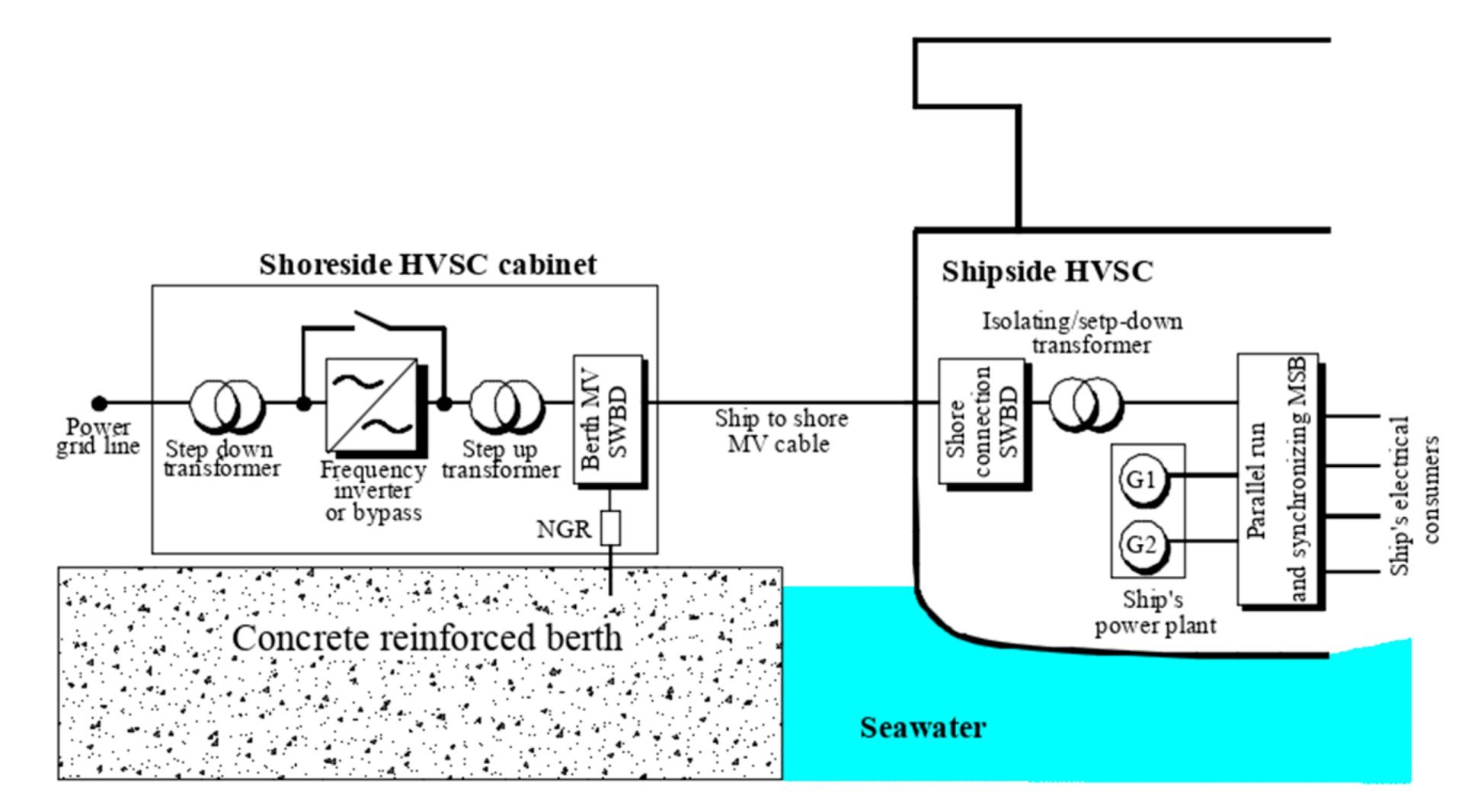
As the main source of supply, medium voltages of 6.6 kV and 11 kV and frequencies of 50 or 60 Hz can be delivered to the ship’s electrical system. For the sake of inland and vessel power grid frequency combability, there must be converter installed that usually is insulated from the ground and connected to the ship thorough a step-up transformer (
Figure 4). Such a connection prevents shoreside supply from injecting unwanted DC currents along with some of harmonics. It must be pointed out that the medium voltage, high power electrical connections in a shore-to-ship system may generate risks, especially for electric shocks or arc fault explosions while connecting the medium voltage plug into the socket. These concerns regard not only the safety of the operators, as the ground fault interferences may cause transferred touch potentials. In addition, such connection can increase the rate of a galvanic corrosion both of the hull of the vessel and steel rebars in the concrete pier. The corrosion of steel-reinforced bars is the major cause of premature failure of reinforced concrete structures, especially in chloride environments.
Classification Societies require [
15], as the grounding system, the IT grid with resistive (or passive) ground connections, which means the star point of the inland step-up transformer should be grounded through a neutral grounding resistor (NGR).
As it can be seen in
Figure 5, one of the most important connections is the equipotential bonding that ties the equipotential node mounted in the hull through the NGR with the neutral point just like in
Figure 5. The neutral grounding resistor limits the fault current to a value that is safe for components of electrical grids and prevents any possible mechanical damages caused by strong magnetic fields occurring during high short-circuit currents flow.
During the cold ironing process, the electric shock hazard is increased by the presence of salty seawater and the decrease of the human body’s total impedance (which drops to 1 kΩ in the presence of voltage exceeding 50 V). This is especially dangerous at the interface area between the concrete berth and the ship [
16,
17,
18,
19]. In the case of HVSC, IT connected systems equipped with neutral earthing resistors, for a shipside fault, the total impedance equals the equipotential wire PE impedance in parallel to the series of the two neutral point connected resistances. As shown in [
18], the main hazards to hull corrosion and the integrity of the pier concrete structure come from direct currents, which are dependent on the equipotential bonding flow. Some interesting information concerning mainly hull protection can be found there and, as one of the problems’ solution, the authors proposed to use active DC cathodic protection while the ships are at berth. There is no available information about hull–pier electrochemical corrosion caused by alternating current flow while cold ironing. To recognize the scale of the potential problem, we investigated the electrical medium voltage connection of the ship with the inland power grid. There are mainly two types of operations: regular with nominal voltages and currents and phase-to-ground or phase-to-phase faults, which leads to unbalanced voltages. When the fault current occurs, it flows through a path that has the lowest impedance and, in the presence of non-zero neutral earthing resistances, almost the whole fault current will flow between the ship’s hull and the concrete pier [
15]. This situation should last for a very short period of time until the protection system trips and shuts the power off. Because of safety reasons, the equipotential bonding is obligatory in HV shore connection systems and must be established solidly between the ship’s hull and the shoreside grounding system. This connection prevents from having any unsafe voltages between the reinforced concrete pier and a hull. The value of the current limiting resistor typically is between 30 Ω and 300 Ω, and in the case of the vessel electrical system depends mainly on the grid voltage value. The main role of resistance when connected between the neutral point and a hull is to limit the short-circuit current during the phase-to-hull fault. Excessive current flow may be a factor contributing to serious generator windings damage. On the other hand, the value of the NGR resistance should allow protection devices to detect the minimum ground fault current that has to be significantly higher than the charging current of the capacitances of the electrical wires and consumers.
Every seagoing ship is equipped with some kind of hull protection system whose main task is to neutralize electrochemical reaction when the ship is moving. Interestingly the same electrochemical processes occur between the steel hull and quay [
18] in the presence of electrolytes, which in this case is seawater (
Figure 6).
These protective systems are of passive and active types and they are commonly known as cathodic protection systems. For smaller vessels there are the so-called sacrificial anodes used, made out of zinc, aluminum, magnesium or their alloys. These anodes decay with time, but this process protects the construction elements like iron and steel, which forms the cathode. What is worth noting is that these protective anodes are efficient only for direct currents “compensation” during electrochemical corrosion. Because of this property, such a system cannot be used for shore-to-ship AC voltage supply purposes. More interesting seems to be the refine solutions using Impressed Current Cathodic Protection (ICCP) systems. As shown in [
18], these systems are sufficient to neutralize DC currents flowing across the PE bonding wire even when the ship is moored. Unfortunately, the currently used ICCPs are not designed to minimalize the AC currents that are also present while cold-ironing. As it turns out, quite some amount of alternating currents is transferred between the hull and pier in the presence of obligatory equipotential bonding, which significantly reduces the shock hazard (touch potential). Cold ironing utilizes long medium voltage cables that can be over 200 meters in length. Such cables have capacitances to the ground that are reactances for alternating currents; thus, its path can be shorted to the ground through a steel hull. Some part of the inland installation (with its capacitances) is present onboard of the vessel so the isolating transformer is not the first device closest to the onboard shore connection box. These capacitances create a path for equalizing and stray currents and a hull becomes an electrical conductor (
Figure 7).
As the numerical experiments show, since these capacitances are symmetrical or, in the other words, have the same values for each phase, the currents flowing between the hull and the pier may be neglected. However, over time the parameters of the medium voltage cables, including the capacitances, are slightly changing. These changes are causing asymmetry; thus, stray currents are no longer symmetrical and an increased flow between the ship and berth occurs.
3. Simulations Results of Current Flow in Cold Ironing
On the basis of an assumption that an inland electrical system and a ship’s power grid are both of the TN-type alternating current with double grounding (and use of NGR resistors), with an isolating transformer installed onboard of the vessel, simulation models were prepared in order to estimate the stray currents values. In order to obtain results as free from harmonics as possible, there has been not considered a situation when the frequency converter is used. The frequency converters in a TN-type grid would add common voltage, which leads to quite high values of direct current flowing between the hull, pier and equipotential bonding in the HVSC [
18]. The parameters of the electrical grid and cable capacitances were altered to reach possible, practical values. Because of the varying values of seawater resistance, this parameter was also changed during the experiments. The capacitances of the cables were obtained from manufacturers catalog carts. The values of the wires to the hull capacitances depend mainly on the length, nominal voltage, conductor diameter and configuration, as well as the insulation thickness along with resistance quality. The latter changes significantly as the insulation material ages and has an environmental impact. The three-phase medium voltage average cables have the capacitance to ground of about 0.3 μF/km and an impedance of roughly 0.25 Ω/km. In some special make military installations, the additional isolating transformers are used in order to avoid grounding capacitances [
20] but in regular HVSC it is not economical. According to the assumptions presented above, the simulations of the stray current flow in shore-to-ship connections were performed in a MATLAB–Simulink environment. The numerical model of isolated low voltage ship system is depicted in the
Figure 8, while the chosen experimental results are presented in
Figure 9,
Figure 10 and
Figure 11. The layout of direct ship-pier HV connection is shown in the
Figure 12 and in the
Figure 13 are depicted waveforms of stray currents present in such type of ship supply.
In the worst-case scenario (
Figure 11), the shore-side cable capacitances are varying with the ship’s MV cables and there is asymmetry in the incoming voltages. Such a cold-ironing operation is almost impossible for a long-time, steady state, but it would happen while transient, like connecting or disconnecting other vessels to the HVSC.
The electrical structure presented in
Figure 8 is a 11 kV HVSC system with NGR on the shore side. There is an assumption made of sinusoidal voltages incoming (no frequency converters). Such a situation occurs when the inland and ship power grid frequencies are aligned (60 Hz in this particular case). Because of notable medium voltage cables lengths, the resistance of the HVSC cable was taken into account and arbitrarily set to a value of 24 milliohms per phase. The cable-to-hull capacitances (of 0.01 μF per phase) on the ship side was added just to depict its presence in all the wiring.
As can be seen, the symmetrical voltage supply and the same per phase capacitances are causing a very low pier hull voltage drop that, in turn, causes flow of negligible stray alternating currents. It can be concluded that, in the case of ideal, symmetrical line parameters, there is no danger of significant corrosion current flow across the hull and concrete structures. Next, the experimental results are indicating that any disturbance in symmetry of the electrical parameters leads to an increase in the stray currents. The presented model includes 100 m wiring to the ship and in this scenario the stray currents are getting close to 0.6 mA.
Interestingly, introducing some asymmetry in the supply voltages have less impact on the hull–pier voltages and currents than the capacitance difference. This is because of the use of a symmetrizing transformer windings connection. This very situation is presented in the simulation results in
Figure 11.
Additionally, some experiments utilizing the ship’s electrical system without an isolation transformer onboard were performed. Such a type of connection is not considered as very safe for ship installation, because the ship’s IT system is galvanically connected with the inland TN-type grid (and its NGR), which would have an impact on the protection system action in the case of a phase-to-ground fault.
Such a simple connection may be found in the case when the voltage amplitude and frequency in the ships electrical system is the same as that incoming from the inland power grid. As it was aforementioned, the value of NGR is small, thus causing a low insulation alarm to be set off. Nonetheless, this kind of ship MV grid is preferred onboard of different types of tankers and chemical carriers.
In such a system, the steady-state current flowing between the hull and pier reaches about 0.13 mA. A particular hazard is the loss of plasticity of the iron alloys as a result of hydrogen diffusion stimulated by short-term stages of cathodic polarization (
Figure 14).
The values of the currents obtained by modelling, after taking into account the cross-sections of the rebar used in the construction of piers, correspond to the current density range of 3 mA/cm
2, defined as dangerous due to the risk of intense hydrogen diffusion into steel [
21] and the occurrence of macro corrosive cells, which pose a threat to the structural integrity of objects [
22,
23].
4. Conclusions and Further Work
For reinforced concrete systems, comparable to offshore facilities, approximately 0.01% of the stray direct current through seawater enters the reinforced concrete and may contribute to the corrosion of the steel and concrete cracking.
A portion of the stray alternating current can be rectified at the reinforcing steel–concrete interface, but the magnitude of the resultant direct current upon reinforced concrete is less than if a direct stray current was involved.
The value of the alternating current flowing through the NGR and ship’s hull depends mainly on capacitances, and on a smaller scale on the neutral grounding resistor value, symmetry of supply and the electrical path hull–water–pier impedance.
Ground faults are the main cause for the DC transient voltages and stray currents, which have to be recognized.
One of solutions to minimize AC stray currents would be introducing some kind of active compensation system. It may be similar to the compensation units used in the IT grid but with the use of controlled current sources, measuring phase stray currents in real-time. In the case of capacitive current detection, the inverters would take action in generating a cancelling-out current.
Possible compromise of covered steel passivity by alternating current in shore-to-ship connection has not yet been investigated.
Right now, there is no suitable simulation software available for shore-to-ship stray current calculations in altering states of operation.
From the point of view of quality management of the port infrastructure maintenance process, it is advisable to continue research on the electrochemical degradation processes in the presence of medium voltage supply systems. It is also advisable to develop and implement control procedures that will reduce the risk of phenomena associated with the formation of macro-corrosive cells and corrosion or hydrogen degradation of steel construction elements. In particular, as shown by the simulations performed, these procedures should include regular checks on the condition of the apparatus and the wiring for capacity symmetry. The use of passive methods of protection against electrochemical phenomena (especially protective coatings) in the underwater part of the pier does not provide comprehensive protection due to erosive effects of the streams coming from the thrusters, therefore minimizing electrical and electrochemical hazards is of fundamental importance.


