Article

Resonant Network Design Method to Reduce Influence of Mutual Inductance between Receivers in Multi-Output Omnidirectional Wireless Power Transfer Systems

The Department of Electrical and Biomedical Engineering, Hanyang University, Seoul 04763, Korea
*
Author to whom correspondence should be addressed.
Energies 2020, 13(21), 5556; https://doi.org/10.3390/en13215556
Submission received: 21 September 2020 / Revised: 19 October 2020 / Accepted: 21 October 2020 / Published: 23 October 2020
(This article belongs to the Section F: Electrical Engineering)

Abstract

:
Many studies have been conducted on multi-output systems that transfer power to multiple receivers in conventional planar-type wireless power transfer (WPT) systems; however, few studies and analyses have taken into account the mutual inductance between receivers in multi-output omnidirectional WPT systems. In this paper, the correlation between the mutual inductance between receivers and the power transfer efficiency (PTE) in a multi-output omnidirectional WPT system is analyzed, and a limitation in terms of a reduction in the PTE with an increase in the influence of the mutual inductance between the receivers is presented. To solve this problem, a resonant network design method is proposed to reduce the influence of mutual inductance between receivers, and appropriate canceling capacitor values are selected using the weighted sum method among multi-objective optimization methods. The proposed method is through simulations and experiments, and it presents the potential for improvement in the problems that occur when transferring power to multiple receivers.

1. Introduction

Studies on wireless power transfer (WPT) systems, which have many advantages over wired power transmission in terms of safety and convenience, are increasing rapidly. As a result, WPT technology has been applied to a variety of applications such as home appliances, electric cars, medical devices, portable devices, and military equipment.
WPT systems can be largely distinguished based on the method of wireless power transmission, which may be directional (using planar-type coils) or omnidirectional (using a coil structure that allows power transmission in any direction). Initial studies on WPT systems were mainly conducted using planar-type transmitter coils and single-receiver situations. To further enhance the practicality of the WPT system, various multi-output studies have been proposed to transfer power to multiple receivers as well as to a single receiver [1,2,3,4,5,6,7,8,9,10,11].
To increase the power transfer efficiency (PTE), a structure of the transmitter that improved the coupling coefficient between the transmitter and receiver was proposed in [1,2,3], and an efficient variable frequency control method was studied in [4,5,6]. In addition, in [7,8], the results of the study were proposed to ensure stable power transmission even with load fluctuations.
As mentioned in [9], the PTE can be affected by the mutual inductance between receivers, and several research results have been presented to solve this problem [10,11]. Reference [10] proposed changes in the capacitors that compensate for changes in the location of the receiver to alleviate the problem of reduction in PTE as the mutual inductance between the receivers increases. However, this approach has disadvantages because it lacks practicality. To overcome this, a method was studied in [11] to select an appropriate pair of compensation capacitors to ensure that the average value of PTE is maximized within the range of specific coupling coefficients between receivers.
Furthermore, an omnidirectional WPT system that can generate magnetic fields in all directions to overcome the shortcomings of the limited positional freedom of the receiver in the existing planar-type WPT system was presented in [12]. Traditional omnidirectional WPT system studies are mainly aimed at transferring power to a single receiver [13,14,15,16,17,18,19].
To increase space utilization and reduce system costs, multi-output omnidirectional WPT systems with multiple receivers were studied [20,21,22,23,24,25,26,27]. Reference [20] proposed a transmitter structure that would cause the density of the magnetic field to be uniform in reliably transferring power to multiple receivers. Various control methods have been proposed, such as a modulation method of the current magnitude or phase angle [21,22,23], a method of physically rotating the transmitter [24], and the use of resonance frequency modulation [25]. In addition, in [26,27], a study of compensation circuits was conducted that reliably transferred power to multiple receivers despite load fluctuations.
However, the existing studies on multi-output omnidirectional WPT systems overlook the mutual inductance between receivers or merely present analytical models containing mutual inductance between receivers; hence, efficient power transfer remains a challenge.
In this study, the correlation between the mutual inductance between receivers and PTE is analyzed to improve the phenomenon of a reduction in PTE owing to an increase in the mutual inductance between receivers in a multi-output omnidirectional WPT system. Based on this theoretical analysis, a resonant network design method is proposed to reduce the influence of mutual inductance between receivers, and appropriate canceling capacitors are selected using the weighted sum method among multi-objective optimization methods. Through the results of simulations and experiments, the performance and validity of the proposed method are verified to present the potential for improvement in the problems occurring in power transmission to multiple receivers in a multi-output omnidirectional WPT system.

2. Multi-Output Omnidirectional Wireless Power Transfer System

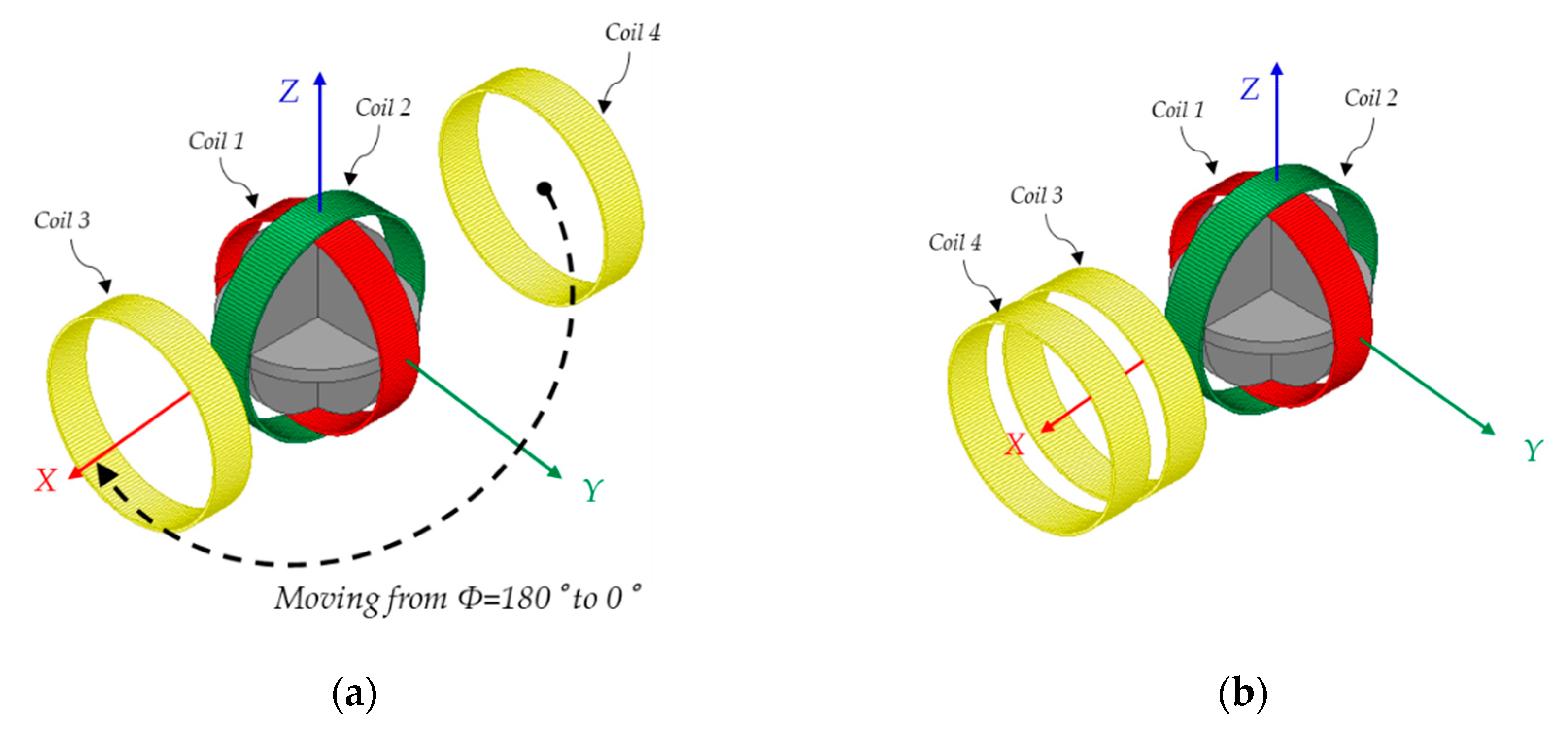
2.1. System Configuration

Figure 1 illustrates the configuration of a multi-output omnidirectional WPT system. Figure 1 presents the configuration and coordinate system of multi-output omnidirectional WPT systems. Coil 1 and coil 2 are coils on the transmitter side. Coil 3 and coil 4 are coils on the receiver side, and the center points of the two receivers are placed over the XY plane. M12 is the mutual inductance between transmitters. M13, M23, M14, and M24 are the mutual inductances between the transmitter and receiver. M34 is the mutual inductance between receivers. Coil 1 and coil 2 are configured to be orthogonal to each other; hence, the mutual inductance between the transmitters M12 is zero and can be ignored. Inside the transmitter, a ferrite core is inserted to increase the power-transfer distance [19]. The position of each coil is represented by a coordinate system, and each component is defined as follows: the distance from point P to the origin is D, the angle with the Z-axis in the positive direction at point P is θ, and the angle with the positive X-axis concerning to the Z-axis at point P is ϕ.
Figure 2 illustrates the system circuit and the equivalent circuit of a multi-output omnidirectional WPT system. Figure 2a presents a system circuit in a multi-output omnidirectional WPT system. Vin is the input voltage, Iin is the input current, Io1 and Io2 are the output currents at each receiver, Vo1 and Vo2 are the output voltages at each receiver, U1 and U2 are the full-bridge output voltages, I1 and I2 are the transmitter currents, and I3 and I4 are the receiver currents. The transmitter consists of a full-bridge converter circuit using switches Qa1,a2,a3,a4 and Qb1,b2,b3,b4, and compensation capacitors C1 and C2 in the series resonant network. The receiver consists of a bridge rectifier circuit using diodes Da1,a2,a3,a4 and Db1,b2,b3,b4, and compensation capacitors C3 and C4 in the series resonant network. L1,2,3,4 is the self-inductance at each coil, R is the parasitic resistance, RL is the load resistor, and Co is the output capacitor.
Figure 2b presents a conversion of Figure 2a into an equivalent circuit of an omnidirectional WPT system taking into account the mutual inductance between multiple receivers. If KVL (Kirchhoff’s Voltage Law) is applied to each circuit, then the following matrix is obtained:
[ U 1 U 2 0 0 ] = [ R + j X 1 0 j w M 13 j w M 14 0 R + j X 2 j w M 23 j w M 24 j w M 13 j w M 23 R + R a c + j X 3 j w M 34 j w M 14 j w M 24 j w M 34 R + R a c + j X 4 ] [ I 1 I 2 I 3 I 4 ]
where Rac = (8/ π 2)RL is the AC equivalent resistance, X1 = wL1−1/wC1, X2 = wL2−1/wC2, X3 = wL3−1/wC3, and X4 = wL4−1/wC4 are the reactance components of each coil, and w is defined as the operating angular frequency.
Equation (1) shows that the receiver current changes owing to changes in the mutual inductance, which can be inferred to affect the PTE. Therefore, to improve the PTE, the relationship between the mutual inductance and PTE must be analyzed.

2.2. Relationship between Mutual Inductance between Receivers and Power Transfer Efficiency

To theoretically analyze the relationship between the mutual inductance and PTE in a multi-output omnidirectional WPT system, the following equations are introduced using Figure 2.
P o u t = P l o a d 1 + P l o a d 2 = ( | I 3 | 2 + | I 4 | 2 ) R a c
P i n = P l o s s 1 + P l o s s 2 + P l o s s 3 + P l o s s 4 + P l o a d 1 + P l o a d 2 = ( | I 1 | 2 + | I 2 | 2 + | I 3 | 2 + | I 4 | 2 ) R + ( | I 3 | 2 + | I 4 | 2 ) R a c
η = P o u t P i n = ( | I 3 | 2 + | I 4 | 2 ) R a c ( | I 1 | 2 + | I 2 | 2 + | I 3 | 2 + | I 4 | 2 ) R + ( | I 3 | 2 + | I 4 | 2 ) R a c
where the sum of power consumed at each AC equivalent resistance is expressed in Equation (2) as output power Pout, the sum of power consumed at each coil’s parasitic resistance and output is expressed as input power Pin, and the relation between the input power and output power is expressed in Equation (4) as PTE η.
In [21], the phase angle control method, in which the magnitude of the transmitter current is equal to I and the phase angle is controlled at 90°, was introduced to create a rotating magnetic field on the XY plane. In this study, the phase angle control method of the transmitter current is applied to transfer power to multiple receivers simultaneously.
Assuming that the system operates at the resonant frequency, the PTE equation is transformed as follows:
η = P o u t P i n = w o 2 R a c 2 { ( R + R a c ) 2 + w o 2 M 34 2 } R ( M 13 2 + M 23 2 ) + ( M 14 2 + M 24 2 ) + w o 2 ( R + R a c )
where Equation (5) shows that the mutual inductance component, which varies with changes in the receiver position, affects the PTE. For a detailed analysis, the system model shown in Figure 3 was created.
Figure 3a depicts a system consisting of an omnidirectional WPT transmitter and a single receiver. To induce mutual inductance between coil 1 and coil 3, the system was simplified as shown in Figure 3b. The distance between the origin and the center of coil 3 is defined as D, the radius of each coil is r, the number of turns for each coil is N, the permeability of free space is μo, and the precondition for inducing mutual inductance is defined as D r and θ = 90°.
The magnetic flux density B from coil 1 to coil 3 is defined as follows [28]:
B 13 = μ 0 N I 1 r 2 4 D 3 ( a D 2 cos ϕ + a ϕ 2 cos ϕ )
where I1 is the current of coil 1, aD is a unit vector of distance D, and aϕ is a unit vector of ϕ.
The magnetic flux Φ13 from coil 1 to coil 3 is defined as follows:
Φ 13 = s u r f a c e _ S 3 B 13 d s = 2 π μ 0 N I 1 r 4 cos ϕ 4 D 3 .
The proportional coefficient of the flux linkage and current is the mutual inductance, where the mutual inductance M13 between coil 1 and coil 3 is given by
M 13 = 2 π μ 0 N r 4 cos ϕ 4 D 3 .
Figure 3c shows that coil 1 physically rotated by 90° is equal to coil 2. In view of this, by replacing ϕ with 90° −ϕ in Equation (8), the mutual inductance M23 between coil 2 and coil 3 can be defined as follows:
M 23 = 2 π μ 0 N r 4 s i n ϕ 4 D 3 .
Equations (8) and (9) indicate that the term M132 + M232 in Equation (5) is consistent with changes in the location of the receiver if the distance D is constant. The term M142 + M242 in Equation (5) is also constant if the same condition applies. Thus, when distance D is constant, the only parameter that changes in Equation (5) as the distance between receivers decreases is the mutual inductance M34 between the receivers, and it can be seen that increasing the corresponding term decreases the PTE. According to these results, the theoretical analysis has shown that as the distance between receivers decreases, the mutual inductance between the receivers increases, thereby decreasing the PTE. This presents a need to reduce the influence of the mutual inductance between receivers.

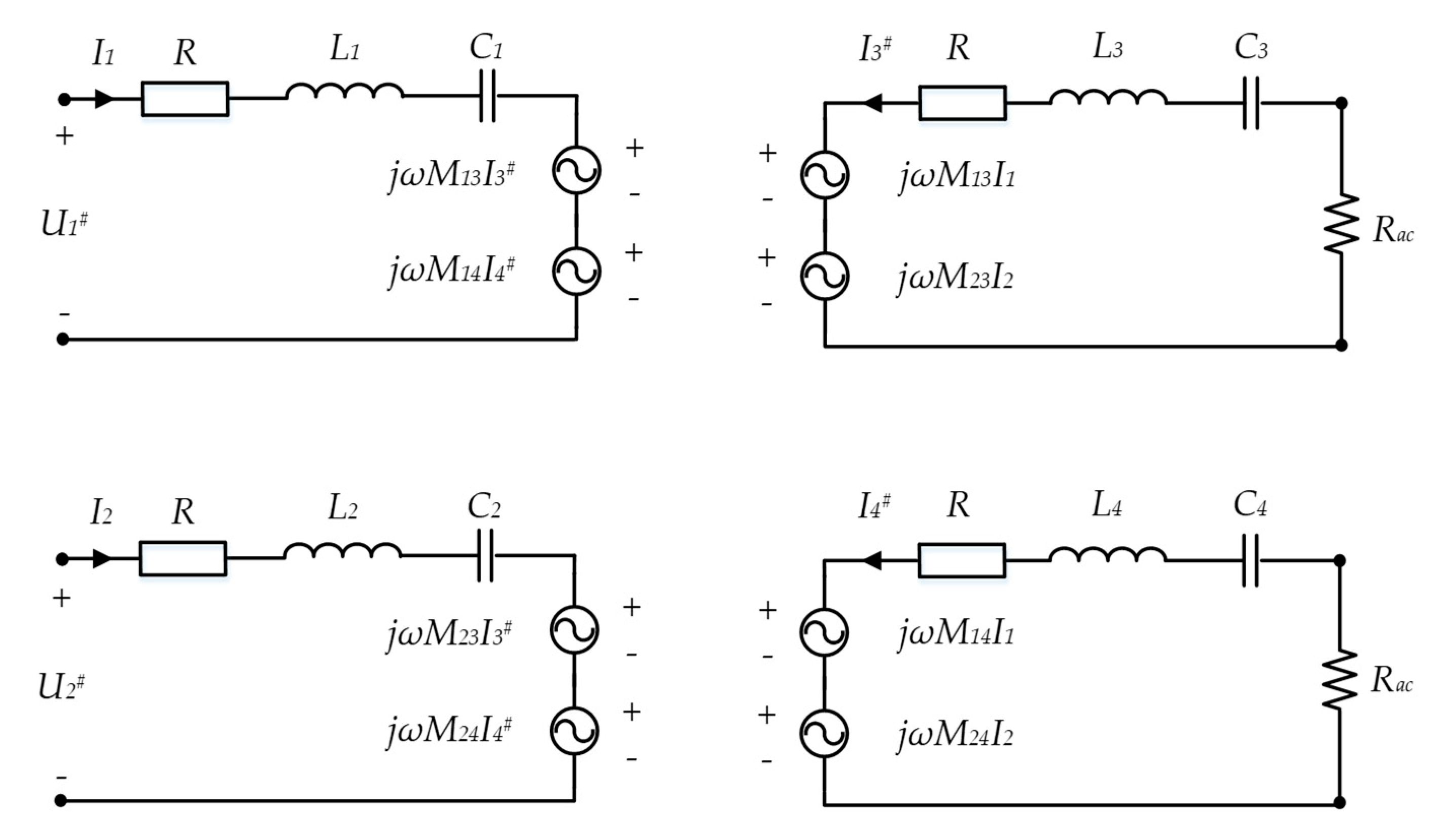
3. Resonant Network Design Method to Reduce Influence of Mutual Inductance between Receivers

3.1. Proposed Design Method

To design a resonance network that reduces the influence of mutual inductance between receivers, an analytical model where the mutual inductance between receivers is ignored is derived as follows.
Figure 4 shows an equivalent circuit in which the mutual inductance between the receivers is ignored. U1# and U2# are full-bridge output voltages, and I3# and I4# are receiver currents when the mutual inductance between receivers is ignored.
Assuming that the system operates at a resonant frequency and that KVL is applied to each circuit, the following equation is derived:
[ U 1 # U 2 # 0 0 ] = [ R 0 j w M 13 j w M 14 0 R j w M 23 j w M 24 j w M 13 j w M 23 R + R a c 0 j w M 14 j w M 24 0 R + R a c ] [ I 1 I 2 I 3 # I 4 # ]
The PTE when ignoring the mutual inductance between receivers is induced in the same manner as in Equation (4):
η # = ( | I 3 # | 2 + | I 4 # | 2 ) R a c ( | I 1 | 2 + | I 2 | 2 + | I 3 # | 2 + | I 4 # | 2 ) R + ( | I 3 # | 2 + | I 4 # | 2 ) R a c .
Equation (5) shows that the PTE is maximized when the mutual inductance between the receivers nears zero. Thus, Equation (11) represents the maximum PTE. Through this, the PTE can be expected to improve by reducing the influence of the mutual inductance between receivers if Equations (10) and (11) are derived by minimizing the influence of the mutual inductance between receivers.
To improve the PTE, an analytical model of adding canceling capacitors in series is presented below. Figure 5 depicts a model with a resonant network that reduces the influence of the mutual inductance between receivers.
If KVL is applied to each circuit by applying the same operating conditions as when deriving Equation (10), then the following equation is derived:
[ U 1 * U 2 * 0 0 ] = [ R 0 j w M 13 j w M 14 0 R j w M 23 j w M 24 j w M 13 j w M 23 R + R a c j 1 w C C 1 j w M 34 j w M 14 j w M 24 j w M 34 R + R a c j 1 w C C 2 ] [ I 1 I 2 I 3 * I 4 * ]
where U1* and U2* are full-bridge output voltages, and I3* and I4* are receiver currents when adding canceling capacitors CC1 and CC2.
To obtain values of the canceling capacitors that reduce the influence of the mutual inductance between the receivers, two voltage equations are derived from Equation (12) as follows:
{ ( R + R a c j 1 w C C 1 ) } I 3 * + j w M 34 I 4 * = j w M 13 I 1 j w M 23 I 2
j w M 34 I 3 * + { ( R + R a c j 1 w C C 2 ) } I 4 * = j w M 14 I 1 j w M 24 I 2 .
To solve Equations (13) and (14), the receiver currents I3# and I4# of the analytical model in which the mutual inductance between the receivers is neglected are substituted for the receiver currents I3* and I4* of the analytical model in which the canceling capacitor is added. However, the values of the canceling capacitors CC1 and CC2 are derived in the form of a complex number, making it impossible to implement. Therefore, Equations (13) and (14) are used to induce canceling capacitors that satisfy the functions of Equations (15) and (16), as follows:
f min 1 ( C C 1 ) = { w 2 M 34 M 24 w M 23 ( 1 w C C 1 ) } 2 + { w 2 M 34 M 14 w M 13 ( 1 w C C 1 ) } 2
f min 2 ( C C 2 ) = { w 2 M 34 M 23 w M 24 ( 1 w C C 2 ) } 2 + { w 2 M 34 M 13 w M 14 ( 1 w C C 2 ) } 2 .
As a result, canceling capacitors satisfying Equations (15) and (16) are defined as follows:
C C 1 = M 23 w 2 M 34 M 24 ,   M 13 w 2 M 34 M 14
C C 2 = M 24 ω 2 M 34 M 23 ,   M 14 ω 2 M 34 M 13
Equations (17) and (18) show that the values of canceling capacitors depend on the characteristics of the application or the user’s design criteria.

3.2. Selection of Canceling Capacitors Using Multi-Objective Optimization Method

Specific criteria are required to select appropriate values of the canceling capacitors. Before establishing the criteria, simulations were conducted on two cases to examine the tendency of the selection of canceling capacitors, and the system parameters used are listed in Table 1.
Figure 6 depicts the simulated situation in which receiver 1 of coil 3 is located at D = 150 mm, θ = 90°, ϕ = 0°, and receiver 2 of coil 4 moves from D = 200 mm, θ = 90°, ϕ = 180° to D = 200 mm, θ = 90°, ϕ = 0°, thus increasing the mutual inductance between receivers in a multi-output WPT system.
The reference parameter used to select the canceling capacitor is the coupling coefficient between receivers, which is defined as follows:
k 34 = M 34 L 3 L 4
Figure 7a shows the PTE when a canceling capacitor is selected based on k34 = 0.178. When ϕ changes from 180° to 30°, the PTE is reduced by 9.72% on average compared to that before the reduction of mutual inductance between receivers; however, when ϕ changes from 25° to 0°, the average improvement is 21.6%. Figure 7b shows the PTE when a canceling capacitor is selected based on k34 = 0.04. When ϕ changes from 180° to 40°, the PTE is reduced by 0.3% on average compared to that before the reduction of mutual inductance between receivers; however, when ϕ changes from 35° to 0°, the average improvement is 7.6%.
Thus, selecting a pair of canceling capacitors by which the PTE is reduced less than before adding canceling capacitors when the mutual inductance between receivers is small and the PTE is increased more than before adding canceling capacitors when the mutual inductance between receivers is large, can be expected to ensure a uniform and high average PTE despite the change in receiver location.
The weighted sum method among multi-objective optimization methods [29] was used to select an appropriate pair of canceling capacitors to meet the following conditions:
P ( x ) = i = 1 k w i f i ( x )
g j ( x ) > 0 ;   j = 1 ~ p .
Equation (20) is defined as a function of the product of the weighting factor wi and the objective function fi, and Equation (21) is a constraint. A solution that satisfies the constraints and simultaneously minimizes Equation (20) is the optimum solution within the user-selected conditions.
f 1 ( x ) = η s t d e v = 1 N 1 i = 1 N ( η i η a v g ) 2
f 2 ( x ) = η a v g = 1 N i = 1 N η i
C C 1 > 0 ,   C C 2 > 0 .
Equation (22) is the first objective function that indicates the standard deviation of the ith PTE ηi and contributes to the uniform distribution of PTE even with changes in the mutual inductance between receivers. Equation (23) is the second objective function that indicates the average PTE and contributes to the creation of a high PTE. Equation (24) defines the constraints of canceling capacitors as designable positive.
In Figure 8, f1norm(x) and f2norm(x) are functions that normalize Equations (22) and (23). The schematization of f1norm(x) and f2norm(x) that meets the constraints is expressed in Figure 8. The weighting factors w1 and w2 are equally set at 0.5. This indicates that the weight of the normalized objective functions f1norm(x) and f2norm(x) is equally considered and the point meeting this condition is the optimal solution. As a result, the canceling capacitors are selected as CC1 = 146 nF and CC2 = 23.8 nF.

4. Simulated and Experimental Results

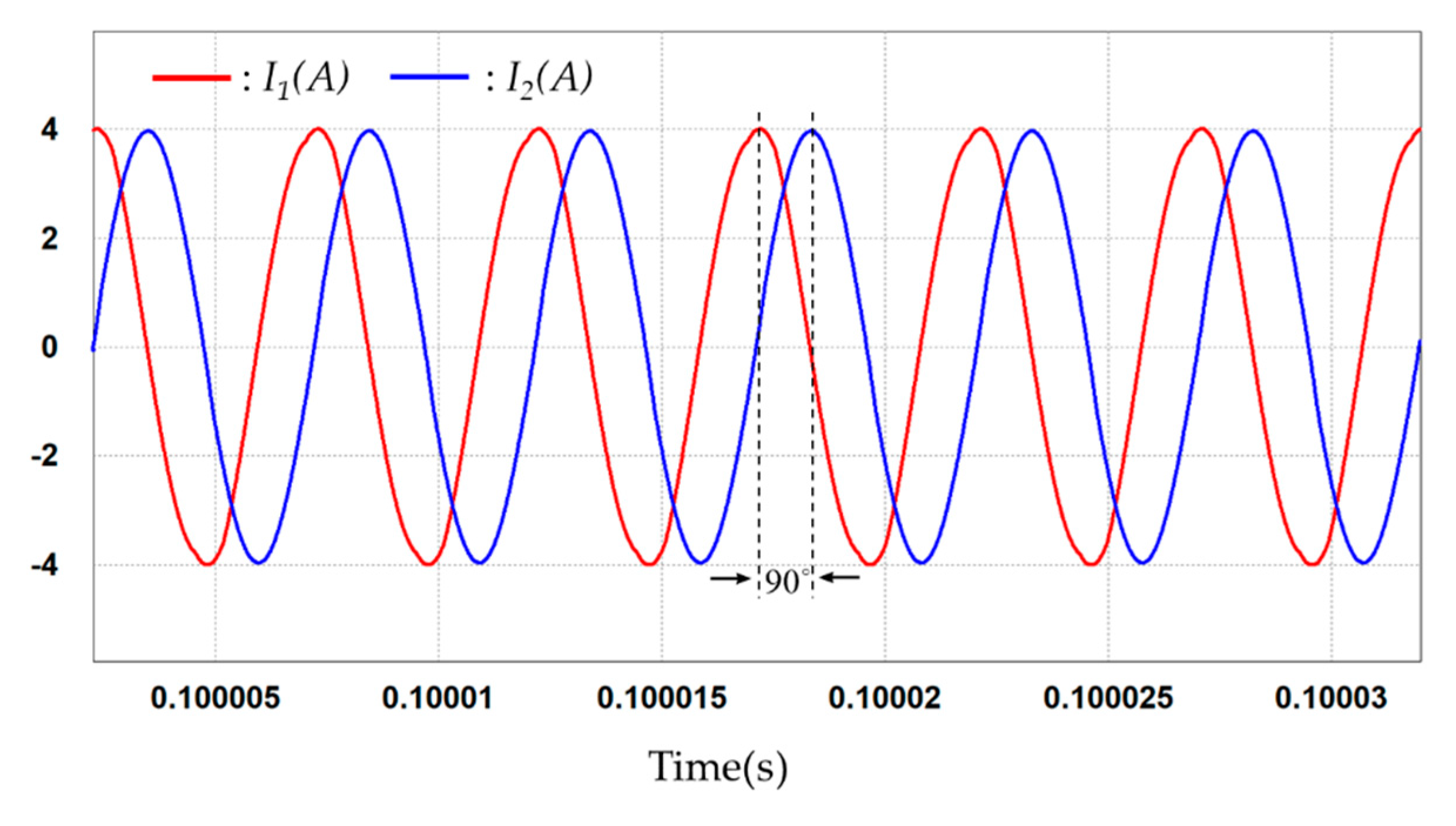
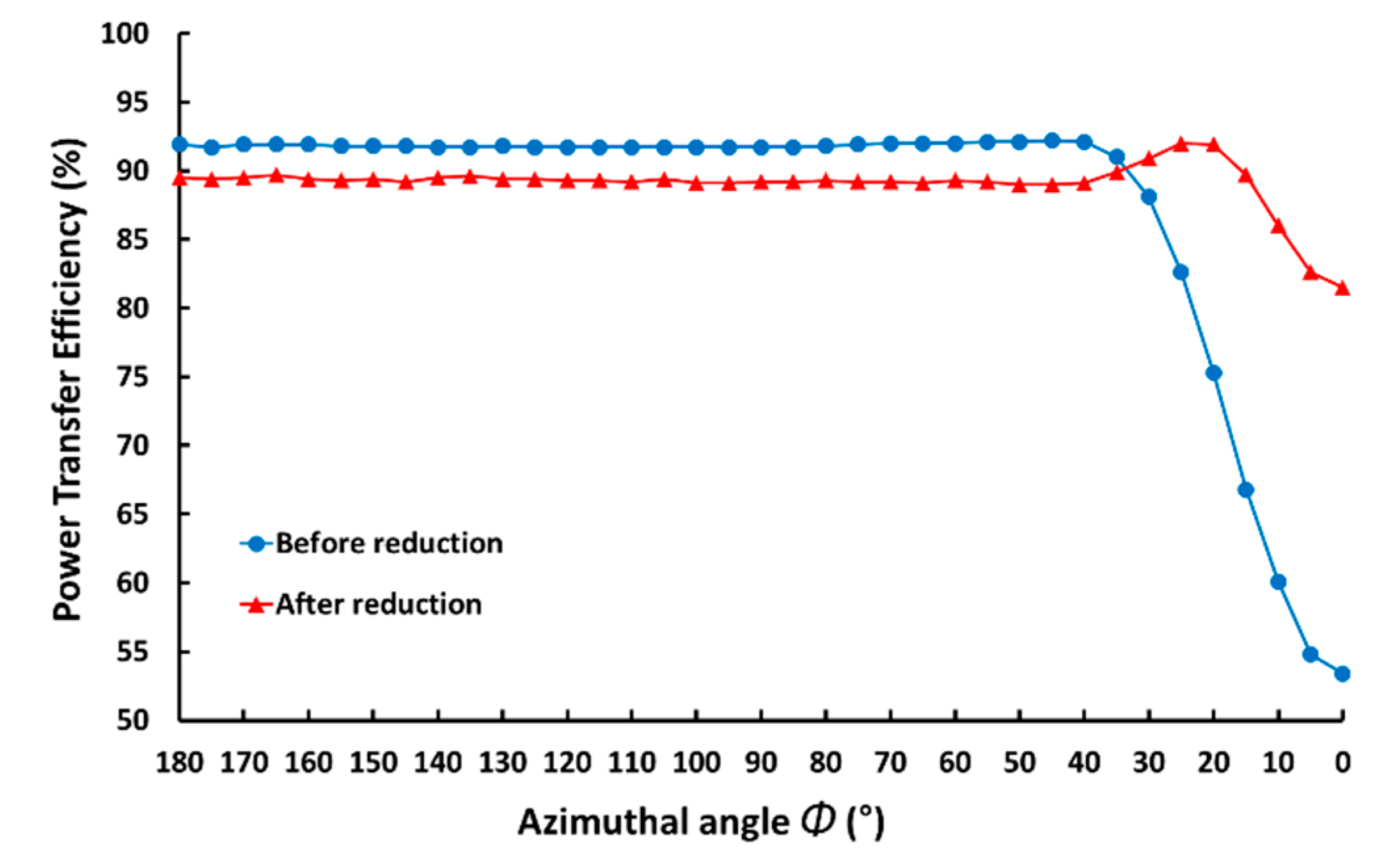
4.1. Simulated Results

The simulated situation is the same as in Figure 6. The canceling capacitors CC1 and CC2 are added in series to the circuit of the receiver, as shown in Figure 9. The canceling capacitor values were derived as CC1 = 146 nF and CC2 = 23.8 nF in the preceding process, and the simulation was carried out using PSIM.
Figure 10 shows the simulated waveform of the transmitter currents. It can be confirmed that the magnitude of the transmitter currents is controlled at 4 A and the phase angle of the transmitter currents is controlled at 90° for simultaneously transferring power to multiple receivers.
Figure 11 shows simulated comparison of the PTE before and after the reduction of the mutual inductance influence between the receivers following the ϕ change in receiver 2. As ϕ decreases from 180° to 0°, the distance between receivers becomes shorter, which means that the mutual inductance between the receivers increases. The average PTE before the reduction was 91.8% in the section where ϕ changes from 180° to 40°, and the average PTE after the reduction was 89.3%, which is about 2.5% less than before the reduction. The average PTE before the reduction in the section where ϕ changes from 35° to 0°, where the mutual inductance between receivers was rapidly increasing, was 71.5%, and the average PTE after reduction was 89.3%, showing an increase of about 17.8% compared to that before reduction. Based on the simulated results, the proposed resonant network design method is confirmed to decrease in the influence of the mutual inductance between receivers and improve PTE.

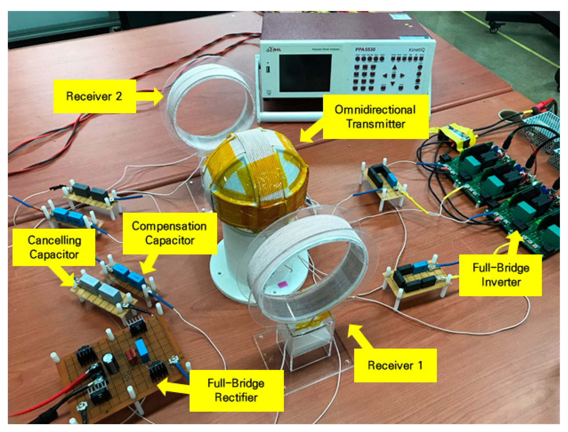
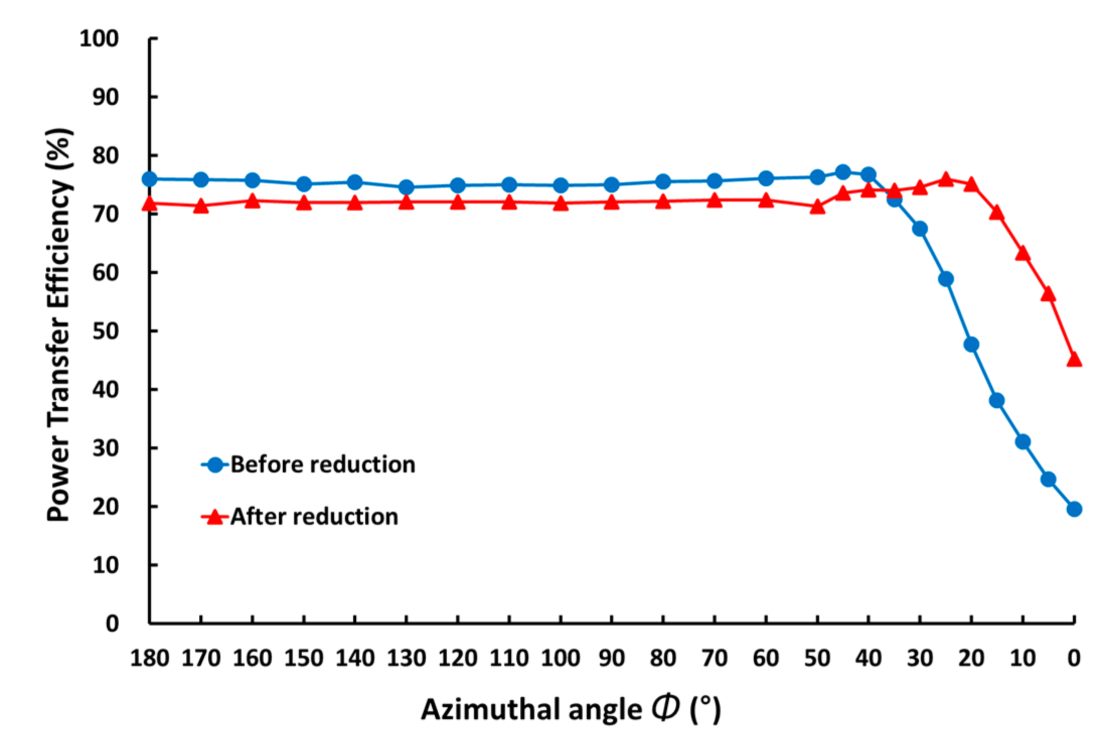
4.2. Experimental Results

Figure 12 presents the experimental configuration of a multi-output omnidirectional WPT system by adding canceling capacitors that reduce the influence of the mutual inductance between receivers. To implement a multi-output omnidirectional WPT, two full-bridge inverters are used to drive an omnidirectional transmitter, and the two receivers are wired to a full-bridge rectifier. For each transmitter and receiver coil, the compensation capacitors are added in series, and the canceling capacitors are added to the receiver sides to reduce the influence of the mutual inductance between the receivers. The situation, parameters, and operating conditions of the experiment are the same as those in the simulation.
Figure 13 shows the experimental waveform of the transmitter currents. It can be seen that the transmitter currents follow the same reference currents as the simulated waveform.
Figure 14 shows an experimental comparison of the PTE before and after the reduction of the mutual inductance influence between the receivers following the ϕ change in receiver 2. As ϕ decreases from 180° to 0°, the distance between receivers becomes shorter, which means that the mutual inductance between the receivers increases. The average PTE before the reduction was 75.6% in the section where ϕ changes from 180° to 40°, and the average PTE after the reduction was 72.2%, which is about 3.4% less than that before the reduction. The average PTE before the reduction in the section where ϕ changes from 35° to 0°, where the mutual inductance between receivers is rapidly increasing, was 45%, and the average PTE after the reduction was 66.9%, showing an increase of about 21.9% compared to that before the reduction. Not only simulated results, but also the experimental results demonstrate that the proposed resonant network design method is confirmed to decrease in the influence of the mutual inductance between receivers and improve PTE.

5. Conclusions

In this study, the correlation between the mutual inductance between receivers and PTE was analyzed to improve the phenomenon of reduction in PTE owing to an increase in the mutual inductance between receivers in a multi-output omnidirectional WPT system. A resonant network design method was proposed to reduce the influence of mutual inductance between receivers, and appropriate canceling capacitors were selected using the weighted sum method among multi-objective optimization methods. Through the results of simulations and experiments, the performance and validity of the proposed method were verified to present the potential for improvement in the problems that occur in power transmission to multiple receivers in a multi-output omnidirectional WPT system.

Author Contributions

Conceptualization, D.-H.W., H.-R.C. and R.-Y.K.; formal analysis, D.-H.W.; investigation, D.-H.W.; methodology, D.-H.W.; project administration, R.-Y.K.; software, D.-H.W.; supervision, H.-R.C. and R.-Y.K.; validation, D.-H.W.; visualization, D.-H.W., H.-R.C. and R.-Y.K.; writing—original draft, D.-H.W.; writing—review and editing, D.-H.W., H.-R.C. and R.-Y.K. All authors have read and agreed to the published version of the manuscript.

Funding

This work was supported by “Human Resources Program in Energy Technology” of the Korea Institute of Energy Technology Evaluation and Planning (KETEP), granted financial resource from the Ministry of Trade, Industry & Energy, Republic of Korea (No. 20184010201710).

Conflicts of Interest

The authors declare no conflict of interest.

References

  1. Liu, X.; Hui, S.Y.R. Optimal design of a hybrid winding structure for planar contactless battery charging platform. IEEE Trans. Power Electron. 2008, 23, 455–463. [Google Scholar]
  2. Casanova, J.J.; Low, Z.N.; Lin, J. A loosely coupled planar wireless power system for multiple receivers. IEEE Trans. Ind. Electron. 2009, 56, 3060–3068. [Google Scholar] [CrossRef]
  3. Jiang, C.; Chau, K.T.; Han, W.; Liu, W. Development of multilayer rectangular coils for multiple-receiver multiple-frequency wireless power transfer. Prog. Electromagn. Res. 2018, 163, 15–24. [Google Scholar] [CrossRef] [Green Version]
  4. Liu, N.; Wang, B. An LLC-based planar wireless power transfer system for multiple devices. In Proceedings of the 2014 IEEE Applied Power Electronics Conference and Exposition-APEC 2014, Fort Worth, TX, USA, 16–20 March 2014. [Google Scholar]
  5. Zhang, Y.; Lu, T.; Zhao, Z.; He, F.; Chen, K.; Yuan, L. Selective wireless power transfer to multiple loads using receivers of different resonant frequencies. IEEE Trans. Power Electron. 2015, 30, 6001–6005. [Google Scholar] [CrossRef]
  6. Hassan, K.; Pan, S.; Jain, P. Multiple receiver wireless power charger for mobile electronic devices in near field. In Proceedings of the IEEE International Conference on Industrial Electronics for Sustainable Energy Systems (IESES), Hamilton, New Zealand, 31 January–2 February 2018. [Google Scholar]
  7. Kim, J.; Kim, D.; Park, Y. Analysis of capacitive impedance matching networks for simultaneous wireless power transfer to multiple devices. IEEE Trans. Ind. Electron. 2015, 62, 2807–2813. [Google Scholar] [CrossRef]
  8. Tan, L.; Zhang, M.; Wang, S.; Pan, S.; Zhang, Z.; Li, J.; Huang, X. The design and optimization of a wireless power transfer system allowing random access for multiple loads. Energies 2019, 12, 1017. [Google Scholar] [CrossRef] [Green Version]
  9. Cannon, B.L.; Hoburg, J.F.; Stancil, D.D.; Goldstein, S.C. Magnetic resonant coupling as a potential means for wireless power transfer to multiple small receivers. IEEE Trans. Power Electron. 2009, 24, 1819–1825. [Google Scholar] [CrossRef] [Green Version]
  10. Fu, M.; Zhang, T.; Zhu, X.; Luk, P.C.; Ma, C. Compensation of cross coupling in multiple-receiver wireless power transfer systems. IEEE Trans. Ind. Inf. 2016, 12, 474–482. [Google Scholar] [CrossRef]
  11. Cui, D.; Imura, T.; Hori, Y. Optimization of cross coupling cancellation for multiple-receiver wireless power transfer system at changing-state. In Proceedings of the Asian Wireless Power Transfer Workshop, Chengdu, China, 16–18 December 2016. [Google Scholar]
  12. O’Brien, K. Inductively Coupled Radio Frequency Power Transmission System for Wireless Systems and Devices; Shaker Verlag: Herzogenrath, Germany, 2007; pp. 21–62. [Google Scholar]
  13. Lin, D.; Zhang, C.; Hui, S.Y.R. Mathematical analysis of omnidirectional wireless power transfer—Part-I: Two-dimensional systems. IEEE Trans. Power Electron. 2017, 32, 625–633. [Google Scholar] [CrossRef]
  14. Lin, D.; Zhang, C.; Hui, S.Y.R. Mathematic analysis of omnidirectional wireless power transfer—Part-II Three-dimensional systems. IEEE Trans. Power Electron. 2017, 32, 613–624. [Google Scholar] [CrossRef]
  15. Ha-Van, N.; Seo, C. Analytical and experimental investigations of omnidirectional wireless power transfer using a cubic transmitter. IEEE Trans. Ind. Electron. 2018, 65, 1358–1366. [Google Scholar] [CrossRef]
  16. Han, W.; Chau, K.T.; Jiang, C.; Liu, W.; Lam, W.H. Design and analysis of quasi-omnidirectional dynamic wireless power transfer for fly-and-charge. IEEE Trans. Magn. 2019, 55, 1–9. [Google Scholar] [CrossRef]
  17. Ye, Z.; Sun, Y.; Liu, X.; Wang, P.; Tang, C.; Tian, H. Power transfer efficiency analysis for omnidirectional wireless power transfer system using three-phase-shifted drive. Energies 2018, 11, 2159. [Google Scholar] [CrossRef] [Green Version]
  18. Feng, J.; Fi, Q.; Lee, F.C.; Fu, M. Transmitter coils design for free-positioning omnidirectional wireless power transfer system. IEEE Trans. Ind. Inf. 2019, 15, 4656–4664. [Google Scholar] [CrossRef]
  19. Park, K.R.; Cha, H.R.; Kim, R.Y. Spherical flux concentration transmitter for omnidirectional wireless power transfer with improved power transmission distance. In Proceedings of the IEEE 4th International Future Energy Electronics Conference (IFEEC), Singapore, 25–28 November 2019. [Google Scholar]
  20. Choi, B.H.; Lee, E.S.; Sohn, Y.H.; Jang, G.C.; Rim, C.T. Six degrees of freedom mobile inductive power transfer by crossed dipole Tx and Rx coils. IEEE Trans. Power Electron. 2016, 31, 3252–3272. [Google Scholar] [CrossRef]
  21. Ng, W.M.; Zhang, C.; Lin, D.; Hui, S.Y.R. Two- and three-dimensional omnidirectional wireless power transfer. IEEE Trans. Power Electron. 2014, 29, 4470–4474. [Google Scholar] [CrossRef] [Green Version]
  22. Lin, D.; Hui, S.Y.R.; Zhang, C. Omni-directional wireless power transfer systems using discrete magnetic field vector control. In Proceedings of the IEEE Energy Conversion Congress and Exposition (ECCE), Montreal, QC, Canada, 20–24 September 2015. [Google Scholar]
  23. Zhang, C.; Lin, D.; Hui, S.Y.R. Basic control principles of omnidirectional wireless power transfer. IEEE Trans. Power Electron. 2016, 31, 5215–5227. [Google Scholar]
  24. Liu, G.; Zhang, B.; Xiao, W.; Qiu, D.; Chen, Y.; Guan, J. Omnidirectional wireless power transfer system based on rotary transmitting coil for household appliances. Energies 2018, 11, 878. [Google Scholar]
  25. Dai, Z.; Fang, Z.; Huang, H.; He, Y.; Wang, J. Selective omnidirectional magnetic resonant coupling wireless power transfer with multiple-receiver system. IEEE Access 2018, 6, 19287–19294. [Google Scholar] [CrossRef]
  26. Han, H.; Mao, Z.; Zhu, Q.; Su, M.; Hu, A.P. A 3D wireless charging cylinder with stable rotating magnetic field for multi-load application. IEEE Access 2019, 7, 35981–35997. [Google Scholar] [CrossRef]
  27. Tan, L.; Zhong, R.; Tang, Z.; Huang, T.; Huang, X.; Meng, T.; Zhai, X.; Wang, C.; Xu, Y.; Yang, Q. Power stability optimization design of three-dimensional wireless power transmission system in multi-load application scenarios. IEEE Access 2020, 8, 91843–91854. [Google Scholar] [CrossRef]
  28. Cheng, D.K. Field and Wave Electromagnetics, 2nd ed.; Pearson: London, UK, 1983; pp. 234–243. [Google Scholar]
  29. Arora, J.S. Introduction to Optimum Design, 3rd ed.; Elsevier: Amsterdam, The Netherlands, 2011; pp. 657–680. [Google Scholar]
Figure 1. System configuration of multi-output omnidirectional wireless power transfer system.
Energies 13 05556 g001
Figure 2. Multi-output omnidirectional wireless power transfer system: (a) system circuit; (b) equivalent circuit in a situation where mutual inductance between receivers is considered.
Energies 13 05556 g002
Figure 3. System model for deriving mutual inductance between transmitter and receiver: (a) System configuration; (b) deriving mutual inductance between coil 1 and coil 3; (c) deriving mutual inductance between coil 2 and coil 3.
Energies 13 05556 g003
Figure 4. Equivalent circuit in a situation where mutual inductance between receivers is neglected.
Energies 13 05556 g004
Figure 5. Equivalent circuit in case of adding canceling capacitors to reduce influence of mutual inductance between receivers.
Energies 13 05556 g005
Figure 6. Situations where mutual inductance between receivers increases: (a) Position of coil 3 is (D = 150 mm, θ = 90°, ϕ = 0°), and position of coil 4 is (D = 200 mm, θ = 90°, ϕ = 180°); (b) position of coil 3 is (D = 150 mm, θ = 90°, ϕ = 0°), and position of coil 4 is (D = 200 mm, θ = 90°, ϕ = 0°).
Energies 13 05556 g006
Figure 7. Power transfer efficiency (PTE) according to each coupling coefficient: (a) k34 = 0.178; (b) k34 = 0.04.
Energies 13 05556 g007
Figure 8. Graphical representation of two-objective optimization problem.
Energies 13 05556 g008
Figure 9. Multi-output omnidirectional wireless power transfer system circuit when adding canceling capacitors.
Energies 13 05556 g009
Figure 10. Simulated result: transmitter currents.
Energies 13 05556 g010
Figure 11. Simulated result: power transfer efficiency (PTE).
Energies 13 05556 g011
Figure 12. Experimental configuration.
Energies 13 05556 g012
Figure 13. Experimental result: transmitter currents.
Energies 13 05556 g013
Figure 14. Experimental result: power transfer efficiency (PTE).
Energies 13 05556 g014
Table 1. System parameters.
ParameterValue (Unit)
Input Voltage (Vin)100 (V)
Resonant Frequency (fo)200 (kHz)
Operating Frequency (f)202 (kHz)
Self-Inductance of Transmitters (L1, L2)93.3 (μH)
Self-Inductance of Receivers (L3, L4)56.6 (μH)
Resonant Capacitor of Transmitters (C1, C2)6.8 (nF)
Resonant Capacitor of Receivers (C3, C4)11.2 (nF)
Radius of Coil (r)75 (mm)
Number of Turns (N)16 (Turns)
Output Capacitor (Co)100 (μF)
Load Resister (RL)5.8 (Ω)
Publisher’s Note: MDPI stays neutral with regard to jurisdictional claims in published maps and institutional affiliations.

