Article

Adaptive Control of Fuel Cell and Supercapacitor Based Hybrid Electric Vehicles

1
School of Electrical Engineering and Computer Science, National University of Sciences and Technology (NUST), Islamabad 44000, Pakistan
2
School of Mechanical and Manufacturing Engineering, National University of Sciences and Technology (NUST), Islamabad 44000, Pakistan
3
School of Electrical Engineering, Shandong University, Jinan 250100, China
*
Author to whom correspondence should be addressed.
Energies 2020, 13(21), 5587; https://doi.org/10.3390/en13215587
Submission received: 24 August 2020 / Revised: 5 October 2020 / Accepted: 12 October 2020 / Published: 26 October 2020
(This article belongs to the Section E: Electric Vehicles)

Abstract

:
In this paper, an adaptive nonlinear control strategy for the energy management of a polymer electrolyte membrane fuel cell and supercapacitor-based hybrid electric vehicle is proposed. The purpose of this work was to satisfy: (i) tight DC bus voltage regulation, (ii) good fuel cell reference current tracking, (iii) better supercapacitor reference current tracking (iv) global asymptotic stability of the closed-loop control system, and (v) better vehicle performance by catering to slowly-varying parameters. We have selected the power stage schematic of a hybrid electric vehicle and utilized adaptive backstepping and adaptive Lyapunov redesign-based nonlinear control methods to formally derive adaptive parametric update laws for all slowly-varying parameters. The performance of the proposed system has been tested under varying load conditions using experimental data from the “Extra Urban Driving Cycle.” Mathematical analysis and Matlab/Simulink results show that proposed controllers are globally asymptotically stable and satisfy all the design requirements. The physical effectiveness of proposed system has been verified by comparing simulation results with the real-time controller hardware in the loop experimental results. Results show that proposed system shows satisfactory performance and caters for the time-varying parametric variations and the load requirements.

1. Introduction

Research on alternate energy sources has gained interest because of the global energy crisis and continuously decreasing fossil fuel reserves. Using fossil fuel, trucks, buses, and cars are the major sources of air pollution [1]. Vehicle manufactures are working on electric vehicles (EVs) in order to meet increasing demands of the consumers for fuel-efficient, clean-energy vehicles [2]. Hybrid electric vehicles (HEVs) provide us an opportunity to resolve the problems related to decreasing oil reserves, global warming and tailpipe pollution [3,4,5].
Multiple energy sources are required to meet the desired power and load requirements of HEVs [6,7,8]. Hybrid energy storage systems (HESS) utilize energy coming from multiple sources by keeping in view the characteristics of each source.
Recently, many control techniques and topologies have been proposed for HESS of HEVs. HESS are mostly based on experience and personal judgment [8]. Researchers are working on multiple combinations of energy sources in order to design an efficient HESS for HEVs. Energy storage systems in HEVs have a main energy source and an auxiliary one [5]. The most common of them are the fuel cell-battery, the fuel cell-supercapacitor, the battery-supercapacitor, and fuel cell photovoltaic panels [4,6,8,9,10,11]. The main energy source provides the long driving range and the alternate energy source works only when sudden acceleration is required or braking is performed. A fuel cell (FC) provides a long driving range because of its improved fuel economy, high density output current, and clean energy generation [12]. The high cost and low power density of the FC are the major issues which limit its use as an energy source. In order to balance the load from a FC, a supercapacitor (SC) can be used as an auxiliary energy source [13]. A SC works during startup, acceleration, sudden load changes, and regenerative braking because of its high power density. The main issue with SC is its low energy density [1,8,10,11,12].
Battery-supercapacitor HESS has been proposed in [4,10,14,15,16,17]; high cost and low energy density are the major issues with lithium-ion batteries. Another hurdle is that the consumers need to replace the batteries periodically, which adds to the cost of HEVs. In FC vehicles, SC can also be used to capture energy loss and charge the battery. Adding SC as a secondary source results in size reduction of each component providing power/energy as compared to vehicles that rely on FC only. Heavy vehicles need more power but their performance can be improved by adequate sizing of energy sources. In case of battery vehicles, the battery bank size needs to be increased in order to achieve more power and energy. This results in unused capacity of extra batteries added to support more power and energy. On the other hand, a fuel cell depends on the hydrogen stored in the hydrogen tank that enables separation of power from stored energy. This allows us to use a fuel cell of comparatively smaller weight for achieving the desired energy and power requirements [18]. Supercapacitors are energy storage systems that, unlike electrochemical batteries, can be instantly charged and give off electricity, compensating in the short-term for tens of megawatts of power, and they also operate in a wider temperature range without maintenance and replacement during the entire service life—at least 15 years. Supercapacitors are based on a unique nano-carbon material in the form of carbon fabric. The innovative design allows you to accumulate a larger charge of electricity compared to similar devices that use carbon powder. In the design of supercapacitors, aqueous electrolytes are used which are environmentally friendly and fire and explosion proof. Thanks to this, Russian supercapacitors are safe for human health and the environment: they can be used in crowded places, including in healthcare facilities, and passenger and commercial transport.
A practical implementation of HESS needs proper control of a DC–DC power converter. A combination of buck and boost converters can be used in order to achieve the desired behavior. Control strategies for fuel cell and supercapacitor-based HESS for HEVs have been proposed in [19,20,21,22,23,24,25,26]. The major issue in these designs is that constant values of resistors, inductors and capacitors have been used. These values are prone to change with time because of wear and tear, production faults, and noise [27]. Nonlinear and adaptive control techniques can be utilized in order to estimate slowly-varying parametric values [28]. An adaptive backstepping -ased controller has been proposed for estimating parameters of an induction motor in [29].
In this paper, adaptive backstepping and adaptive Lyapunov redesign-based controllers have been proposed for controlling the HESS of fuel cell and supercapacitor-based hybrid electric vehicles. The main concept is to design a closed-loop control system which keeps on updating in order to cater for slowly varying parametric values of resistors, capacitors, and inductors. The objectives of controller design are to obtain stable DC bus voltage, good current tracking for the two energy sources, and power load distribution for HEVs under varying load conditions. Mathematical analysis and simulation results show that both the proposed nonlinear controllers, coupled with adaptive parameter estimate laws, are globally asymptotically stable; hence, we made the following contributions:
  • Efficient power distribution between the fuel cell and supercapacitor is done in order to improve the efficiency of the HEV under varying load conditions.
  • Slowly-varying converter model parameters are estimated using adaptive update laws such thatthe controller updates itself by keeping in mind parametric variations.
  • Proposed nonlinear controllers, including the Lyapunov-based adaptive controller and adaptive backstepping controller, do not need exact model parameters. These controllers can cater to slowly-varying parametric variations and uncertainties.
  • The proposed system has been tested on experimental data from the Extra Urban Driving Cycle (EUDC). The physical effectiveness of the proposed system was validated using real-time controller hardware in the loop experiments.
  • The proposed nonlinear controllers converge tracking errors to zero.
  • HESS was proven to be globally asymptotically stable using a Lyapunov-based stability criterion.
This paper is organized as follows: Section 2 illustrates mathematical modeling of the HESS. Section 3 summarizes the control strategy, which includes the power distribution scheme, Lyapunov-based adaptive controller design and backstepping-based adaptive controller design for the hybrid energy storage system of a hybrid electric vehicle. Section 4 validates the proposed controllers by presenting simulation results and hardware in the loop experiments. Section 5 concludes the work and presents future enhancements of this work.

2. The Hybrid Energy Storage System Modeling

Figure 1 shows a power stage schematic of the proposed HESS which consists of a boost and a boost-buck converter for the fuel cell and supercapacitor respectively.
Power is distributed in order to divide the load between the fuel cell and the supercapacitor and to achieve good performance in varying load conditions. The HESS improves efficiency and reliability by storing extra energy recovered from regenerative braking. The HESS is designed to efficiently deliver energy under different load conditions.
In case of constant load conditions, the fuel cell works as a primary source and continually provides energy to the HEV. The fuel cell keeps working until hydrogen fuel is available. It can also charge the supercapacitor, depending on the state of charge.
Fuel cells alone cannot provide efficient energy under high load conditions because of the starvation phenomenon. Supercapacitors have high power density and provide energy for a short period of time. A supercapacitor works as an auxiliary source and provides peak power during sudden acceleration and high load transients. It stores additional energy from regenerative braking. The following subsections present a mathematical model for the fuel cell and supercapacitor-based HESS for HEVs:

2.1. Fuel Cell—Boost Converter Model

The electrochemical source, the fuel cell, acts as a primary source in HEV and meets constant load requirements. The output voltage fromthe fuel cell can be represented by Nernst’s instantaneous voltage equation [30]:
V o u t F C = E V l o s s e s
where V l o s s e s consists of all fuel cell losses, including ohmic, concentration, and activation losses given as:
V l o s s e s = V o h m + V c o n c e n t r a t i o n + V a c t i v a t i o n
where V o h m , V c o n c e n t r a t i o n , and V a c t i v a t i o n are ohmic, concentration, and activation voltages respectively. All of these losses can be represented by resistances R o h m i c , R c o n , and R a c t respectively. Equivalent capacitance is represented by C.
The proton exchange membrane fuel cell (PEMFC) is used because of its compact size and fast startup [31]. The tuel cell is connected to a boost converter [32] as shown in Figure 1. The boost converter portion consists of a MOSFET switch S 1 , an inductor L 1 , an output capacitor C 0 , a diode D 1 and resistance R 1 respectively. Low input voltage from the fuel cell can be boosted to a high voltage level using a boost converter. Switch S 1 is controlled with the help of a PWM signal. When S 1 is turned on, the inductor L 1 starts storing energy depending on the rate of change of current with respect to time. When S 1 is turned off, voltage is induced because of energy stored in the inductor. Induced voltage adds to the input voltage. The diode D 1 is used to avoid recharging of the fuel cell by conducting electric current in only one direction. These two voltages collectively charge the capacitor C 0 to a voltage which is comparatively higher than input voltage. One can easily obtain the mathematical model for boost converter by applying Kirchoff’s current law to the circuit shown in Figure 1:
d i F C d t = 1 L 1 v F C R 1 L 1 i F C 1 u 1 L 1 v o
d v o d t = 1 C 0 1 u 1 i F C i 1
where i F C is the current passing through inductor L 1 , v F C is fuel cell voltage, u 1 is the control input for switch S 1 , v o is the output voltage of the DC bus, and i 1 is the output current of the boost converter.

2.2. Supercapacitor—Boost-Buck Converter Model

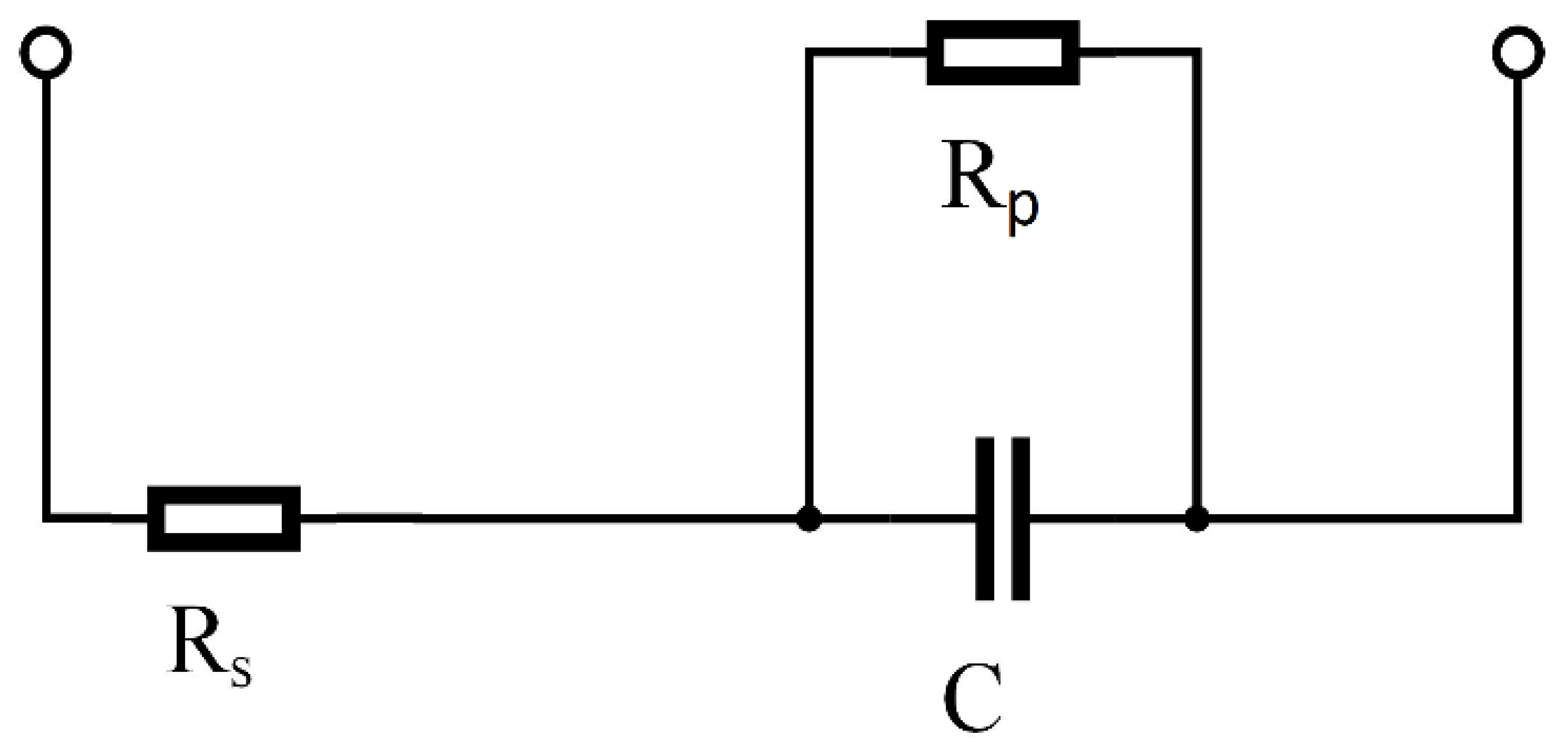
The RC equivalent circuit of a supercapacitor consists of a series equivalent resistor and a parallel equivalent resistor represented by R s and R p respectively in Figure 2 [33].
R p is added in parallel to the equivalent capacitor C. The output voltage from a supercapacitor can be represented as:
V o u t U C = V i e t / R p C
where V i is initial voltage before discharging, t is time, and V o u t U C is output voltage from UC.
The following equation shows energy E o u t U C t drawn from the supercapacitor:
E o u t U C = 1 2 C ( V i 2 V f 2 )
where V i is the initial voltage before discharging and V f is the final voltage after discharging.
The boost-buck converter works as a boost converter in discharging mode and as a buck converter in charging mode. During charging, the buck converter model is given by [5]:
d i U C d t = v o L 2 u 3 R 2 L 2 i U C + v U C L 2
i 2 = u 3 · i U C
where i U C is the current passing through inductor L 2 , v U C is the supercapacitor voltage, u 3 is the control input for switch S 3 , and i 2 is the output current of the boost-buck converter.
Similarly, during discharging, the boost converter model becomes:
d i UC d t = v 0 L 2 ( 1 u 2 ) R 2 L 2 i U C + v SC L 2
i 2 = ( 1 u 2 ) · i U C
where u 2 is input for switch S 2 . Combine (8) and (10) for rate of change of supercapacitor current. A combined boost-buck model can be obtained by defining another variable u 23 :
u 23 = s 1 u 2 + 1 s u 3
where switching function s is given by:
s = 0 , if i u c r e f < 0 ( Buck Mode ) 1 , if i u c r e f > 0 ( Boost Mode )
where i u c r e f is the reference current for supercapacitor.
Combining the models of boost and buck converters by using the switching function, following the boost-buck converter model, can be done:
d i U C d t = u 23 v dc L 2 R 2 L 2 i UC + v UC L 2
i 2 = u 23 i UC

2.3. Combined Dynamical Model for HEV

Combining the equations for boost and buck-boost converters, a complete mathematical model of HESS for HEV is obtained as:
d i FC d t = 1 L 1 V F C R 1 L 1 i F C 1 u 1 v 0 L 1 d i UC d t = u 23 v 0 L 2 R 2 L 2 i UC + v UC L 2 d v 0 d t = 1 u 1 i FC C 0 + u 23 i UC C 0 i o C 0 i o = i 1 + i 2
where load current i o is the sum of the output current of the boost converter i 1 and the output current of the boost-buck converter i 2 .
Accurate values of parameters R 1 , R 2 , L 1 , L 2 and C 0 slowly vary with time and are not very precise in practice. Defining these parameters as slowly-varying parameters, the following substitutions are performed:
θ 1 = 1 L 1 = 1 L 2 ; θ 2 = R 1 L 1 = R 2 L 2 ; θ 3 = 1 C 0 ; x 1 = i FC ; x 2 = i UC ; x 3 = V 0
where θ 1 , θ 2 , and θ 3 are slowly-varying parameters. Using the above substitutions, the simplified mathematical model (14) for HEV takes the form:
d x 1 d t = θ 2 x 1 1 u 1 θ 1 x 3 + θ 1 V f c d x 2 d t = θ 2 x 2 u 23 θ 1 x 3 + θ 1 V U C d x 3 d t = ( 1 u 1 ) θ 3 x 1 + u 23 θ 3 x 2 θ 3 i 0

3. Controller Design for HEV

In this section, the power distribution strategy for HEV to efficiently distribute power between FC and SC will be devised. The strategy will be used to design adaptive control laws based on Lyapunov and backstepping-based nonlinear controllers.

3.1. The Power Distribution Strategy for HEV

Figure 3 shows the distribution strategy for power management of supercapacitors and fuel cells under varying load conditions. This strategy is designed for HESS by keeping in mind the performance requirements of HEVs. The fuel cell and supercapacitor operate simultaneously in order to provide the required load power as shown by following equation:
P load = P FC r e f + P UC r e f P FC r e f = V fc I FC r e f P UC r e f = V uc I UC r e f
where
  • P load = required load power (kW);
  • P FC r e f = reference power of fuel cell (kW);
  • P UC r e f = reference power of supercapacitor (kW);
  • P UC r e f comes from remaining load power required (kW);
  • I FC r e f = reference current for fuel cell (A);
  • I UC r e f = reference current for supercapacitor (A).
The reference power for the fuel cell and supercapacitor is given by (16). The proposed power distribution strategy can be used to find reference values for fuel cell and supercapacitor currents respectively. Equation (16) is used as a part of the Extra Urban Driving Cycle (EUDC) [5].
The power distribution strategy was designed by keeping in mind the physical properties of the fuel cell and supercapacitor. The idea is to utilize the fuel cell most of the time as the primary energy source because of its high energy density. The fuel cell will continuously supply power under steady and low-load conditions because of its low power density. On the other hand, the supercapacitor has high power density, which makes it ideal for high transient load conditions. The supercapacitor is used as a secondary energy source because it has low energy density as it discharges quickly by providing high power to the vehicle. The power management strategy is summarized as follows:
  • The fuel cell works most of the time during low power demands. The remaining power is used to charge the supercapacitor. The charging and discharging of supercapacitor are done according to load requirements.
  • During high power demands, the fuel cell is supported by the supercapacitor, for a short period of time, in order to meet high power requirements.
The aforementioned strategy was implemented by using the nonlinear controllers, and the results are presented. This method was employed because it (1) distributes power in real-time using nonlinear controllers for speed control; (2) does not need prior knowledge of the driving cycle; (3) distributes power between the fuel cell and supercapacitor by considering the properties of these sources and the varying power demands of vehicle; (4) simple, online implementation. Optimization-based methods, neural networks, and artificial intelligence can be used in order to guarantee optimal operation of HESS, but such methods (1) work offline; (2) need heavy computational resources; (3) ignore practical vehicle power demands, such as the power required to accelerate in the presence of friction and gravity; (4) are difficult to implement [34]. In the next step, we will formally derive controller equations for the Lyapunov-based adaptive controller and the backstepping-based adaptive controller respectively. Initially we assume that all the parameters are known and then we design an adaptive parametric update law for unknown time-varying parameters.

3.1.1. Lyapunov-Based Adaptive Controller Design

In the proposed power distribution strategy, u 0 is the control input. The following is the design procedure of the adaptive nonlinear controller. Rewriting (14) and (15) for controller design gives:
x 1 ˙ = θ 2 x 1 1 u 1 θ 1 x 3 + θ 1 V f c x 2 ˙ = θ 2 x 2 u 23 θ 1 x 3 + θ 1 V U C x 3 ˙ = ( 1 u 1 ) θ 3 x 1 + u 23 θ 3 x 2 θ 3 i 0 i o = i 1 + i 2
Error variables z 1 , z 2 , and z 3 are defined as:
z 1 = x 1 I F C r e f z 2 = x 2 I U C r e f z 3 = x 3 v 0 r e f
where v 0 ref represents the desired value of v 0 .
The time derivative of error variables in (18), z 1 , z 2 , and z 3 can be calculated as:
z ˙ 1 = x ˙ 1 I ˙ F C r e f z ˙ 2 = x ˙ 2 I ˙ U C r e f z ˙ 3 = x ˙ 3 v ˙ 0 r e f
Substituting the values of x ˙ 1 , x ˙ 2 , and x ˙ 3 from (17) in (19), gives
z ˙ 1 = θ 2 x 1 1 u 1 θ 1 x 3 + θ 1 V f c I ˙ F C r e f z ˙ 2 = θ 2 x 2 u 23 θ 1 x 3 + θ 1 V UC I ˙ U C r e f z ˙ 3 = ( 1 u 1 ) θ 3 x 1 + u 23 θ 3 x 2 θ 3 i 0 v ˙ 0 r e f
In the next step, corresponding adaptive estimation errors are defined θ ˜ 1 , θ ˜ 2 , and θ ˜ 3 for θ 1 , θ 2 , and θ 3 respectively as:
θ ˜ 1 = θ ^ 1 θ 1 θ ˜ 2 = θ ^ 2 θ 2 θ ˜ 3 = θ ^ 3 θ 3
where θ ^ 1 , θ ^ 2 , and θ ^ 3 are estimates of θ 1 , θ 2 , and θ 3 respectively.
In order to prove stability of the proposed system, following Lyapunov candidate function is designed:
V = 1 2 z 1 2 + 1 2 z 2 2 + 1 2 z 3 2 + 1 2 γ 1 θ ˜ 1 2 + 1 2 γ 2 θ ˜ 2 2 + 1 2 γ 3 θ ˜ 3 2
where γ 1 , γ 2 , and γ 3 are gains of adaptive law.
Taking time derivative of (22) gives:
V ˙ = z 1 z ˙ 1 + z 2 z ˙ 2 + z 3 z ˙ 3 + 1 γ 1 θ ˜ 1 θ ˜ ˙ 1 + 1 γ 2 θ ˜ 2 θ ˜ ˙ 2 + 1 γ 3 θ ˜ 3 θ ˜ ˙ 3
Substituting the values of z ˙ 1 , z ˙ 2 , and z ˙ 3 from (20), results in the following rate of change of the Lyapunov function with respect to time:
V ˙ = z 1 ( θ ^ 2 x 1 1 u 1 θ ^ 1 x 3 + θ ^ 1 V F C I ˙ F C r e f ) + z 2 θ ^ 2 x 2 u 23 θ ^ 1 x 3 + θ ^ 1 V UC I ˙ U C r e f + z 3 ( 1 u 1 ) θ ^ 3 x 1 + u 23 θ ^ 3 x 2 θ ^ 3 i 0 v ˙ 0 r e f + θ ˜ 1 z 1 1 u 1 x 3 V F C + 1 γ 1 θ ^ ˙ 1 + θ ˜ 2 z 1 x 1 + z 2 x 2 + 1 γ 2 θ ^ ˙ 2 + z 2 ( u 23 x 2 V U C ) + θ ˜ 3 ( 1 u 1 ) z 3 x 1 u 23 z 3 x 2 + z 3 i 0 + 1 γ 3 θ ^ ˙ 3
Adaptive parametric estimate laws are designed by solving (24)
θ ^ ˙ 1 = γ 1 θ ^ 1 , z 1 1 u 1 x 3 + V F C + z 2 ( u 23 x 3 + V U C ) θ ^ ˙ 2 = γ 2 ( θ ^ 2 , z 1 x 1 z 2 x 2 ) θ ^ ˙ 3 = γ 3 θ ^ 3 , z 3 ( 1 u 1 ) x 1 + u 23 x 2 i 0
Note that adaptive control is different from robust control because a priori information about the boundedness of uncertain slowly-varying parameters is not required. A robust control law is designed by keeping in mind the following Proj θ ^ operator:
Proj θ ^ = 0 if θ ^ = θ ^ max and τ > 0 0 if θ ^ = θ ^ max and τ < 0 τ otherwise
where θ ^ max is the upper bound of θ ^ . Proj θ ^ stands for the projection operator which guarantees the boundedness of the estimated parameters by projecting them to bounded intervals [35,36,37]. Substituting the values of θ ^ ˙ 1 , θ ^ ˙ 2 and θ ^ ˙ 3 from (25) in (24), gives the following inequality:
V ˙ z 1 ( θ ^ 2 x 1 1 u 1 θ ^ 1 x 3 + θ ^ 1 V F C I ˙ F C r e f ) + z 2 θ ^ 2 x 2 u 23 θ ^ 1 x 3 + θ ^ 1 V UC I ˙ U C r e f + z 3 ( 1 u 1 ) θ ^ 3 x 1 + u 23 θ ^ 3 x 2 θ ^ 3 i 0 v ˙ 0 r e f
In order to achieve the tracking objectives defined in Section 1, the errors z 1 , z 2 , and z 3 should decay to zero with time and overall system should be stable. The Lyapunov stability criterion, V ˙ 0 , can be satisfied by designing a constraint condition for control laws using (26):
θ ^ 2 x 1 1 u 1 θ ^ 1 x 3 + θ ^ 1 V F C I ˙ F C r e f = c 1 z 1 + z 3
θ ^ 2 x 2 u 23 θ ^ 1 x 3 + θ ^ 1 V UC I ˙ U C r e f = c 2 z 2
( 1 u 1 ) θ ^ 3 x 1 + u 23 θ ^ 3 x 2 θ ^ 3 i 0 v ˙ 0 r e f = c 3 z 3
where c 1 > 0, c 2 > 0, and c 3 > 0 are control design parameters.
Solving (27)–(29) respectively, gives the following control laws:
u 1 = 1 1 θ ^ 1 x 3 c 1 z 1 z 3 θ ^ 2 x 1 + θ ^ 1 V f c I ˙ F C r e f
u 23 = 1 θ ^ 1 x 3 c 2 z 2 θ ^ 2 x 2 + θ ^ 1 V UC I ˙ U C r e f
v ˙ 0 r e f = c 3 z 3 + ( 1 u 1 ) θ ^ 3 x 1 + u 23 θ ^ 3 x 2 θ ^ 3 i 0
Substituting the values of u 1 , u 23 , and v ˙ 0 r e f from (26)–(32), gives
V ˙ z 1 ( c 1 z 1 ) + z 2 ( c 2 z 2 ) + z 3 z 1 + z ˙ 3
For V ˙ in (33) to be negative definite, z ˙ 3 can be chosen as:
z ˙ 3 = c 3 z 3 z 1
Substituting z ˙ 3 from (34) in (33), the equations can be obtained:
V ˙ c 1 z 1 2 c 2 z 2 2 c 3 z 3 2
Note that z 3 also behaves as a damping term and converges to zero if both z 1 and z 2 converge. Moreover, (35) shows that V ˙ is negative definite which satisfies the Lyapunov stability criterion and proves that the proposed control system is globally asymptotically stable.

3.1.2. Backstepping-Based Adaptive Controller Design

Adaptive backstepping is a step-by-step recursive process and remains simple for higher order mathematical models. For simplicity, it is assumed that the unknown or slowly-varying parametric estimates are already known. The controller designed using this method will be similar to the one designed using the adaptive backstepping controller proposed in [38], but the procedure will be simple.
Step 1:
Define the tracking error as
z 11 = x 1 I F C r e f
Taking time derivative of (36) gives:
z ˙ 11 = x ˙ 1 I ˙ F C r e f
Substituting the value of x ˙ 1 from (17) in (37), gives:
z ˙ 11 = θ 2 x 1 1 u 1 θ 1 x 3 + θ 1 V f c I ˙ F C r e f
Define the Lyapunov candidate function as:
V 11 = 1 2 z 11 2
Taking time derivative of Lyapunov function V 11 gives:
V ˙ 11 = z 11 z ˙ 11
Substituting the values of z ˙ 11 from (38) in (40) and simplifying gives:
V ˙ 11 = z 11 ( θ ^ 2 x 1 1 u 1 θ ^ 1 x 3 + θ ^ 1 V f c I ˙ F C r e f )
According to the Lyapunov stability criterion, V ˙ 11 should be less than zero in order to prove the system as globally asymptotically stable. This needs following substitution:
θ ^ 2 x 1 1 u 1 θ ^ 1 x 3 + θ ^ 1 V f c I ˙ F C r e f = c 11 z 11
where c 11 > 0 is design constant.
Selecting θ ^ 1 x 3 as virtual control ∝, and solving for it gives:
= 1 1 u 1 c 11 z 11 θ ^ 2 x 1 + θ ^ 1 V f c I ˙ F C r e f
Note that the combined system will only be stable when ∝ is equal to θ ^ 1 x 3 because ∝ is only a virtual control. The following error variables are defined:
z 12 = θ ^ 1 x 3
Substituting the value of θ ^ 1 x 3 from (65) in (59) gives:
z ˙ 11 = θ ^ 2 x 1 1 u 1 ( z 12 + ) + θ ^ 1 V f c I ˙ F C r e f
Substituting the value of ∝ from (43) in (45) gives:
z ˙ 11 = c 11 z 11 ( 1 u 1 ) z 12
Therefore, V ˙ 11 given by (47) becomes:
V ˙ 11 = c 11 z 11 2 ( 1 u 1 ) z 11 z 12
Taking the time derivative of z 12 in (44) results in the following equation:
z ˙ 12 = θ ^ 1 x ˙ 3 ˙
Substituting the value of x ˙ 3 from (17) and simplifying Equation (48) gives:
z ˙ 12 = θ ^ 1 1 u 1 θ ^ 3 x 1 + u 23 θ ^ 3 x 2 θ ^ 3 i 0 1 1 u 1 ( u ˙ 1 c 11 z 11 2 c 11 ( 1 u 1 ) z 12 θ ^ 2 x ˙ 1 I ¨ F C r e f )
The composite Lyapunov function can be defined as:
V c = V 11 + 1 2 z 12 2
Taking the derivative of (50) with respect to time, the following equation can be obtained:
V ˙ c = V ˙ 11 + z 12 z ˙ 12
Substituting the value of V ˙ 11 from (47) in (51) results in following equation:
V ˙ c = c 11 z 11 2 z 12 ( 1 u 1 ) z 11 z ˙ 12
In order to ensure V ˙ c to be negative definite, substitute
( 1 u 1 ) z 11 z ˙ 12 = c 12 z 12
where c 12 is positive design coefficient.
The composite Lyapunov function given by (52) becomes:
V ˙ c = c 11 z 11 2 c 12 z 12 2
Equation (54) proves that V ˙ c is negative definite. This ensures that the desired tracking objectives are achieved. In order to ensure that V ˙ c remains negative definite, substitute (49) in (51) and solve for u ˙ 1 , giving:
u ˙ 1 = α 1 ( 1 u 1 ) c 12 z 12 ( 1 u 1 ) 2 z 11 + ( 1 u 1 ) 2 x 1 θ ^ 1 θ ^ 3 ( 1 u 1 ) u 23 x 2 θ ^ 1 θ ^ 3 ( 1 u 1 ) θ ^ 1 θ ^ 3 i 0 β
where
β = ( c 11 θ ^ 2 ) c 11 z 11 1 u 1 z 12 θ ^ 2 I ˙ F C r e f I ¨ F C r e f
So far, the control law tracks both the fuel cell current and the DC output voltage to the desired values.
In the next step, the control law for tracking supercapacitor current to its desired value will be derived. Let us define another error as:
z ˙ 2 = x ˙ 2 I ˙ U C r e f
Substituting the value of x ˙ 2 from (17) in (57) gives:
z ˙ 2 = θ ^ 2 x 2 u 23 θ ^ 1 x 3 + θ ^ 1 V UC I ˙ U C r e f
Define the Lyapunov candidate function as:
V 13 = 1 2 z 2 2
Taking time derivative of (59) and using (57) gives:
V ˙ 13 = z 2 θ ^ 2 x 2 u 23 θ ^ 1 x 3 + θ ^ 1 V UC I ˙ U C r e f
In order to make V ˙ 13 a negative definite, assume:
c 13 z 2 = θ ^ 2 x 2 u 23 θ ^ 1 x 3 + θ ^ 1 V UC I ˙ U C r e f
which gives following final control law for tracking supercapacitor current:
u 23 = 1 θ ^ 1 x 3 c 13 z 2 θ ^ 2 x 2 + θ ^ 1 V UC I ˙ U C r e f
In order to cater for the parametric variations, a Lyapunov candidate function V m can be defined as:
V m = 1 2 z 11 2 + 1 2 z 12 2 + 1 2 z 2 2 + 1 2 γ 1 θ ˜ 1 2 + 1 2 γ 2 θ ˜ 2 2 + 1 2 γ 3 θ ˜ 3 2
Taking time derivative of V m gives:
V ˙ m = z 11 z ˙ 11 + z 12 z ˙ 12 + z 2 z ˙ 2 + 1 γ 1 θ ˜ 1 θ ˜ ˙ 1 + 1 γ 2 θ ˜ 2 θ ˜ ˙ 2 + 1 γ 3 θ ˜ 3 θ ˜ ˙ 3
Substituting values of z ˙ 11 , z ˙ 12 , z ˙ 2 and solving gives:
V ˙ m = z 11 ( θ ^ 2 x 1 1 u 1 θ ^ 1 x 3 + θ ^ 1 V f c I ˙ F C r e f ) + z 2 θ ^ 2 x 2 u 23 θ ^ 1 x 3 + θ ^ 1 V UC I ˙ U C r e f + z 12 ( 1 u 1 ) θ ^ 3 x 1 + u 23 θ ^ 3 x 2 θ ^ 3 i 0 v ˙ 0 r e f + θ ˜ 1 z 1 1 u 1 x 3 V F C + 1 γ 1 θ ^ ˙ 1 + θ ˜ 2 z 1 x 1 + z 2 x 2 + 1 γ 2 θ ^ ˙ 2 + z 2 ( u 23 x 2 V U C ) + θ ˜ 3 ( 1 u 1 ) z 12 x 1 u 23 z 12 x 2 + z 12 i 0 + 1 γ 3 θ ^ ˙ 3
Adaptive parametric estimate laws are designed by using (65) as:
θ ^ ˙ 1 = γ 1 [ z 11 ( 1 u 1 ) x 3 + V F C + z 2 ( u 23 x 3 + V U C ) ] θ ^ ˙ 2 = γ 2 ( z 11 x 1 z 2 x 2 ) θ ^ ˙ 3 = γ 3 [ z 12 { ( 1 u 1 ) x 1 + u 23 x 2 i 0 } ]
By substituting the values of ∝ and u 23 in (62) and using (66), the Equation (65) takes the form:
V ˙ m = c 11 z 11 2 c 12 z 12 2 c 13 z 2 2

4. Results and Discussion

In this section, simulation results of proposed controllers are presented for HEV. Simulation results were validated in real-time using hardware in the loop (HIL) experiments and the results are presented.

4.1. MATLAB Simulation Results

The Extra Urban Driving Cycle (EUDC) was used to validate the performance of the controllers. EUDC is known for a high speed, aggressive driving mode that represents driving a vehicle in extra urban highway conditions [5]. The proposed system was simulated using the ODE45 solver of MATLAB/Simulink software. The value of γ 1 , γ 2 , and γ 3 was set to 0.1 for adaptation. Values of control design coefficients were c 1 = 100, c 11 = 100, c 2 = 1000 , c 12 = 1000, c 3 = 100, and c 13 = 100. The fuel cell used was of 48 KW, 200 V, and 200 A. The SC module used in this study had 141 cells. All cells were connected in series and had total capacitance of 1500 F. Each inductor used in DC–DC converter circuit was of 3.3 mH. Each resistor had a resistance of 20 m ohms. An output capacitor of 1.66 mF was used. Note that these are initial values of resistors, inductors, and capacitors. These values are prone to change with the passage of time. Such slowly-varying parameters are adapted by the help of adaptive laws. The controller updates itself according to time-varying parameters.
Simulation results for backstepping-based adaptive controller are presented in Figure 4 and Figure 5. Simulation results for Lyapunov-based adaptive controller are presented in Figure 6 and Figure 7. Figure 8 compares current tracking errors of both controllers. Figure 9 compares the DC bus voltage tracking performance of adaptive backstepping and Lyapunov-based adaptive controllers.
Figure 4 shows that the backstepping-based adaptive controller had good tracking performance for fuel cell and supercapacitor-based HESS. Although the fuel cell current had a small undershoot at the start, it efficiently tracked the desired reference currents. Figure 5 shows control inputs which help with achieving the desired current and voltage. The backstepping-based controller needs cheap hardware because of fewer input variations in the same time duration. This improves the reliability of the equipment used for this purpose. The backstepping=based adaptive controller performs well under varying load conditions.
Figure 6 shows the fuel cell and supercapacitor current tracking performance for the Lyapunov-based adaptive controller. It shows that the Lyapunov-based adaptive controller had a good performance for tracking of fuel cell current for HEV. The controller also tracked the desired supercapacitor current with some steady state error which could be reduced by giving the desired offset to the output current using filters.
Figure 7 shows the controller’s input variations performed by the Lyapunov based adaptive controller which helped with achieving desired fuel cell and supercapacitor currents. In the case of the Lyapunov-based adaptive controller, fast switching is required for achieving the desired current behavior. This may need comparatively costly hardware which supports fast switching.
Figure 8 shows that current tracking error in the case of the backstepping-based adaptive controller is less as compared to the Lyapunov-based adaptive controller. The zoomed version shows that the backstepping-based adaptive controller has less voltage spikes as compared to the Lyapunov-based adaptive controller.
In Figure 8, if no adaptive law is used, the tracking error will perform better. The adaptive law is not very robust and can only cater to slow parametric variations. Values of resistors, inductors, and capacitors slowly vary with time and are not very precise in practice; Figure 9 presents the comparison of DC bus voltage tracking which shows that the backstepping-based adaptive controller performed well and tracked the desired bus voltages very nicely but had small steady state error and voltage spikes. The Lyapunov-based adaptive controller also tracked the desired DC bus voltage with some voltage spikes/undershoots, but it recovered quickly. Simulation results show that the proposed controllers have good tracking performance. The adaptive control law helps in achieving the desired DC bus voltage in the presence of model uncertainties and parametric variations. Although adaptive controllers are not very robust, they keep updating themselves in order to provide good performance even if the system degrades with time.

4.2. Experimental Results

In order to further verify performance of the proposed system, real-time controller hardware in the loop (C-HIL) experiments have been performed to generate the backstepping-based adaptive control signals for a DC–DC converter, as shown in Figure 10.
The experimental setup consisted of Dual-Core DelfinoTM MS320F2837xD micro-controllers. C-HIL experiments are an affordable way to validate controller performance [39]. The DC–DC converter for a hybrid electric vehicle environment was modeled in Matlab/Simulink and experimental results are compared with the simulation results. Figure 11 shows the DC bus voltage tracking performance. Although there are minor fluctuations in experimental results, as compared to simulation results, the controller shows satisfactory performance and ensures stable DC bus voltage. Figure 12 and Figure 13 show the fuel cell current and supercapacitor current respectively.
As shown in Figure 13, the supercapacitor is charged when supercapacitor current is positive, and discharged when sueprcapacitor current is negative. The supercapacitor will be charged using the fuel cell in the case of low load conditions when the vehicle is running at a constant speed. The fuel cell works a primary source and continually provides energy to the HEV. The fuel cell keeps working until hydrogen fuel is available. The fuel cell can also charge the supercapacitor depending on its state of charge. Supercapacitor stores additional energy from regenerative braking. Current tracking results show some steady state error, but the overall controller performance was satisfactory. The experimental results verified the simulation results, showing that the controller exhibited a satisfactory performance.
Adaptive controllers benefit the real vehicle’s design in the long term because inductors, capacitors, and resistors are prone to degrade with time. Vehicle performance is affected if parameters are not optimized. Adaptive control law updates itself in order to adapt according to slowly-varying parameters. The proposed control logic depends on a hydrogen fuel cell for its operation, and improves fuel efficiency (uses less hydrogen) by using a supercapacitor as a secondary source for catering to transient needs. The fuel cell works most of the time during low power demands. The remaining power is used to charge the supercapacitor. During high power demands, the fuel cell is supported by the supercapacitor. Vehicle performance is also improved because the supercapacitor gives a turbo boost to the vehicle for startup, acceleration, and climbing slopes. Controller design is simple with additional adaptive control laws to make the vehicle more reliable by adapting to unknown parametric variations. This helps in keeping the vehicle to factory specifications. In future, we will design a hybrid energy storage system to save hydrogen by using other energy sources, such as batteries and photovoltaic panels.

5. Conclusions

In this paper, two nonlinear adaptive control strategies have been proposed for the energy management of fuel cell and supercapacitor-based hybrid electric vehicles. A fuel cell has been used as the main source with a supercapacitor as a secondary source. The power distribution strategy has been designed in order to achieve rigorous DC bus voltage requirements. Backstepping and Lyapunov-based nonlinear controllers have been proposed in order to track the desired reference values. Adaptive law has then been employed to estimate the unknown time-varying model parameters. The global asymptotic stability of the proposed controllers has been proven using Lyapunov theory. The proposed system has been tested using experimental data from the Extra Urban Driving Cycle. Results show that the proposed controllers have good tracking performance in the presence of time-varying parameters. In order to verify the controllers’ performances, controller hardware in the loop experiments have been conducted. Experimental results indicate that the proposed controllers keep the DC bus voltage stable under varying load conditions. The supercapacitor proves to be really helpful in high load conditions where fuel cell fails to deliver. In future we will add more sources such as batteries and photo-electro-chemical cells in order to further improve overall vehicle performance.

Author Contributions

Conceptualization, M.S.N. and I.A.; methodology, M.S.N.; software, M.S.N.; validation, M.S.N. and H.A.; formal analysis, M.J.K. and Y.A.; investigation, M.J.K.; resources, Y.A.; data curation, M.S.N. and I.A.; writing—original draft preparation, M.S.N. and I.A.; writing—review and editing, M.S.N., I.A., M.J.K., Y.A. and H.A.; visualization, M.S.N.; supervision, I.A., M.J.K., Y.A.; project administration, Y.A.; funding acquisition, M.J.K. and Y.A. All authors have read and agreed to the published version of the manuscript.

Funding

This research received no external funding.

Acknowledgments

This work is supported by the National University of Sciences and Technology (NUST), Islamabad Pakistan.

Conflicts of Interest

The authors declare no conflict of interest.

References

  1. Heydari, S.; Fajri, P.; Rasheduzzaman, M.; Sabzehgar, R. Maximizing Regenerative Braking Energy Recovery of Electric Vehicles Through Dynamic Low-Speed Cutoff Point Detection. IEEE Trans. Transp. Electrif. 2019, 5, 262–270. [Google Scholar] [CrossRef]
  2. Reimers, J.; Dorn-Gomba, L.; Mak, C.; Emadi, A. Automotive Traction Inverters: Current Status and Future Trends. IEEE Trans. Veh. Technol. 2019, 68, 3337–3350. [Google Scholar] [CrossRef]
  3. Sumathi, P.; Azhagumurugan, R. Novel modular multiple input bi-directional dc-dc power converter using fuzzy network for HEV/FCV application. In Proceedings of the 2016 International Conference on Computation of Power, Energy Information and Commuincation (ICCPEIC), Chennai, India, 20–21 April 2016; pp. 439–444. [Google Scholar]
  4. Joshi, M.C.; Samanta, S.; Srungavarapu, G. Battery ultracapacitor based DC motor drive for electric vehicles. In Proceedings of the 2017 IEEE Region 10 Symposium (TENSYMP), Cochin, India, 14–16 July 2017; pp. 1–5. [Google Scholar]
  5. Fadil, H.E.; Giri, F.; Guerrero, J.M.; Tahri, A. Modeling and Nonlinear Control of a Fuel Cell/Supercapacitor Hybrid Energy Storage System for Electric Vehicles. IEEE Trans. Veh. Technol. 2014, 63, 3011–3018. [Google Scholar] [CrossRef] [Green Version]
  6. Lai, C.M.; Lee, D.; Cheng, Y.H.; Cheng, C.C. An integrated two-input three-output DC/DC boost converter with fuel-cell/battery energy resources for HEV and DC-distribution system. In Proceedings of the 2016 IEEE Transportation Electrification Conference and Expo, Asia-Pacific (ITEC Asia-Pacific), Busan, Korea, 1–4 June 2016; pp. 370–374. [Google Scholar]
  7. Li, Y.; Yang, D.; Ruan, X. A systematic method for generating multiple-input dc/dc converters. In Proceedings of the 2008 IEEE Vehicle Power and Propulsion Conference, Harbin, China, 3–5 September 2008; pp. 1–6. [Google Scholar]
  8. Zhang, R.; Tao, J.; Zhou, H. Fuzzy Optimal Energy Management for Fuel Cell and Supercapacitor Systems Using Neural Network Based Driving Pattern Recognition. IEEE Trans. Fuzzy Syst. 2019, 27, 45–57. [Google Scholar] [CrossRef] [Green Version]
  9. Wu, B.; Yufit, V.; Campbell, J.; Offer, G.J.; Martinez-Botas, R.F.; Brandon, N.P. Simulated and experimental validation of a fuel cell-supercapacitor passive hybrid system for electric vehicles. In Proceedings of the IET Hybrid and Electric Vehicles Conference 2013 (HEVC 2013), London, UK, 6–7 November 2013; pp. 1–6. [Google Scholar]
  10. Kim, Y.; Raghunathan, V.; Raghunathan, A. Design and Management of Battery-Supercapacitor Hybrid Electrical Energy Storage Systems for Regulation Services. IEEE Trans. Multi Scale Comput. Syst. 2017, 3, 12–24. [Google Scholar] [CrossRef]
  11. Xu, D.; Liu, Q.; Yan, W.; Yang, W. Adaptive Terminal Sliding Mode Control for Hybrid Energy Storage Systems of Fuel Cell, Battery and Supercapacitor. IEEE Access 2019, 7, 29295–29303. [Google Scholar] [CrossRef]
  12. Ahrabi, R.R.; Ardi, H.; Elmi, M.; Ajami, A. A Novel Step-Up Multiinput DC–DC Converter for Hybrid Electric Vehicles Application. IEEE Trans. Power Electron. 2017, 32, 3549–3561. [Google Scholar] [CrossRef]
  13. Marchesoni, M.; Vacca, C. New DC–DC Converter for Energy Storage System Interfacing in Fuel Cell Hybrid Electric Vehicles. IEEE Trans. Power Electron. 2007, 22, 301–308. [Google Scholar] [CrossRef]
  14. Lu, X.; Chen, Y.; Fu, M.; Wang, H. Multi-Objective Optimization-Based Real-Time Control Strategy for Battery/Ultracapacitor Hybrid Energy Management Systems. IEEE Access 2019, 7, 11640–11650. [Google Scholar] [CrossRef]
  15. Nguyen, B.; German, R.; Trovão, J.P.F.; Bouscayrol, A. Real-Time Energy Management of Battery/Supercapacitor Electric Vehicles Based on an Adaptation of Pontryagin’s Minimum Principle. IEEE Trans. Veh. Technol. 2019, 68, 203–212. [Google Scholar] [CrossRef] [Green Version]
  16. Peng, H.; Wang, J.; Shen, W.; Shi, D.; Huang, Y. Controllable regenerative braking process for hybrid battery–ultracapacitor electric drive systems. IET Power Electron. 2018, 11, 2507–2514. [Google Scholar] [CrossRef]
  17. Olama, A.; Mendes, P.R.C.; Camacho, E.F. Lyapunov-based hybrid model predictive control for energy management of microgrids. Transm. Distrib. IET Gener. 2018, 12, 5770–5780. [Google Scholar] [CrossRef]
  18. López-Pérez, M.; Claudio-Sánchez, A.; Cano-Castillo, U.; Loyola-Morales, F. Hybrid electric power plant sizing strategy based on ab-initio fuel cell design for weight minimization. Int. J. Hydrog. Energy 2020, 45, 21738–21753. [Google Scholar] [CrossRef]
  19. Lai, C.M.; Lin, Y.J.; Hsieh, M.H.; Li, J.T. A newly-designed multiport bidirectional power converter with battery/supercapacitor for hybrid electric/fuel-cell vehicle system. In Proceedings of the 2016 IEEE Transportation Electrification Conference and Expo, Asia-Pacific (ITEC Asia-Pacific), Busan, Korea, 1–4 June 2016; pp. 163–166. [Google Scholar]
  20. Boulon, L.; Pera, M.C.; Hissel, D.; Bouscayrol, A.; Delarue, P. Energetic Macroscopic Representation of a Fuel Cell-Supercapacitor System. In Proceedings of the 2007 IEEE Vehicle Power and Propulsion Conference, Arlington, TX, USA, 9–12 September 2007; pp. 290–297. [Google Scholar]
  21. Tani, A.; Camara, M.B.; Dakyo, B.; Azzouz, Y. DC/DC and DC/AC Converters Control for Hybrid Electric Vehicles Energy Management-Ultracapacitors and Fuel Cell. IEEE Trans. Ind. Informa. 2013, 9, 686–696. [Google Scholar] [CrossRef]
  22. Burke, A.F. Batteries and Ultracapacitors for Electric, Hybrid, and Fuel Cell Vehicles. Proc. IEEE 2007, 95, 806–820. [Google Scholar] [CrossRef]
  23. Tani, A.; Camara, M.B.; Dakyo, B.; Azzouz, Y. Embedded energy management based on DC/DC converters—Ultracapacitors and Fuel Cell. In Proceedings of the 2012 IEEE International Conference on Industrial Technology, Athens, Greece, 19–21 March 2012; pp. 198–204. [Google Scholar]
  24. Armghan, H.; Ahmad, I.; Ali, N.; Munir, M.F.; Khan, S.; Armghan, A. Nonlinear Controller Analysis of Fuel Cell–Battery–Ultracapacitor-based Hybrid Energy Storage Systems in Electric Vehicles. Arab. J. Sci. Eng. 2018, 43, 3123–3133. [Google Scholar] [CrossRef]
  25. Khan, M.S.; Ahmad, I.; Armaghan, H.; Ali, N. Backstepping sliding mode control of FC-UC based hybrid electric vehicle. IEEE Access 2018, 6, 77202–77211. [Google Scholar] [CrossRef]
  26. Rahman, A.U.; Ahmad, I.; Malik, A.S. Variable structure-based control of fuel cell-supercapacitor-battery based hybrid electric vehicle. J. Energy Storage 2020, 29, 101365. [Google Scholar] [CrossRef]
  27. Redman-White, W.; Kennedy, H.; Bodnar, R.; Lee, T. Adaptive Tuning of Large-Signal Resonant Circuits Using Phase-Switched Fractional Capacitance. IEEE Trans. Circuits Syst. II Express Briefs 2017, 64, 1072–1076. [Google Scholar] [CrossRef] [Green Version]
  28. Zhang, Q.; Deng, W.; Li, G. Stochastic Control of Predictive Power Management for Battery/Supercapacitor Hybrid Energy Storage Systems of Electric Vehicles. IEEE Trans. Ind. Inform. 2018, 14, 3023–3030. [Google Scholar] [CrossRef]
  29. Lee, H.; Fu, L.; Lian, F. Sensorless Adaptive Backstepping Speed Control of Induction Motor. In Proceedings of the 45th IEEE Conference on Decision and Control, San Diego, CA, USA, 13–15 December 2006; pp. 1252–1257. [Google Scholar]
  30. Chavan, S.L.; Talange, D.B. Electrical equivalent circuit modeling and parameter estimation for PEM fuel cell. In Proceedings of the 2017 Innovations in Power and Advanced Computing Technologies (i-PACT), Vellore, India, 21–22 April 2017; pp. 1–6. [Google Scholar]
  31. Khan, S.S.; Rafiq, M.A.; Shareef, H.; Sultan, M.K. Parameter optimization of PEMFC model using backtracking search algorithm. In Proceedings of the 2018 5th International Conference on Renewable Energy: Generation and Applications (ICREGA), Al Ain, United Arab Emirates, 25–28 February 2018; pp. 323–326. [Google Scholar]
  32. Sahu, P.; Verma, D.; Nema, S. Physical design and modelling of boost converter for maximum power point tracking in solar PV systems. In Proceedings of the 2016 International Conference on Electrical Power and Energy Systems (ICEPES), Bhopal, India, 14–16 December 2016; pp. 10–15. [Google Scholar]
  33. Kai, W.; Baosen, R.; Liwei, L.; Yuhao, L.; Hongwei, Z.; Zongqiang, S. A review of modeling research on supercapacitor. In Proceedings of the 2017 Chinese Automation Congress (CAC), Jinan, China, 20–22 October 2017; pp. 5998–6001. [Google Scholar]
  34. Zhang, L.; Ye, X.; Xia, X.; Barzegar, F. A real-time energy management and speed controller for an electric vehicle powered by a hybrid energy storage system. IEEE Trans. Ind. Inform. 2020, 16, 6272–6280. [Google Scholar] [CrossRef]
  35. Jiang, B.; Xu, D.; Shi, P.; Lim, C.C. Adaptive neural observer-based backstepping fault tolerant control for near space vehicle under control effector damage. IET Control. Theory Appl. 2014, 8, 658–666. [Google Scholar] [CrossRef]
  36. Sun, W.; Zhang, Y.; Huang, Y.; Gao, H.; Kaynak, O. Transient-Performance-Guaranteed Robust Adaptive Control and Its Application to Precision Motion Control Systems. IEEE Trans. Ind. Electron. 2016, 63, 6510–6518. [Google Scholar] [CrossRef]
  37. Xu, D.; Jiang, B.; Shi, P. Adaptive Observer Based Data-Driven Control for Nonlinear Discrete-Time Processes. IEEE Trans. Autom. Sci. Eng. 2014, 11, 1037–1045. [Google Scholar] [CrossRef] [Green Version]
  38. Krstić, M.; Kanellakopoulos, I.; Kokotović, P.V. Nonlinear and Adaptive Control Design Volume 7 of Adaptive and Learning Systems for Signal Processing, Communications, and Control; Wiley: Hoboken, NJ, USA, 1995. [Google Scholar]
  39. Rosa, A.H.; Silva, M.B.; Campos, M.F.; Santana, R.A.; Rodrigues, W.A.; Morais, L.M. Shil and dhil simulations of nonlinear control methods applied for power converters using embedded systems. Electronics 2018, 7, 241. [Google Scholar] [CrossRef] [Green Version]
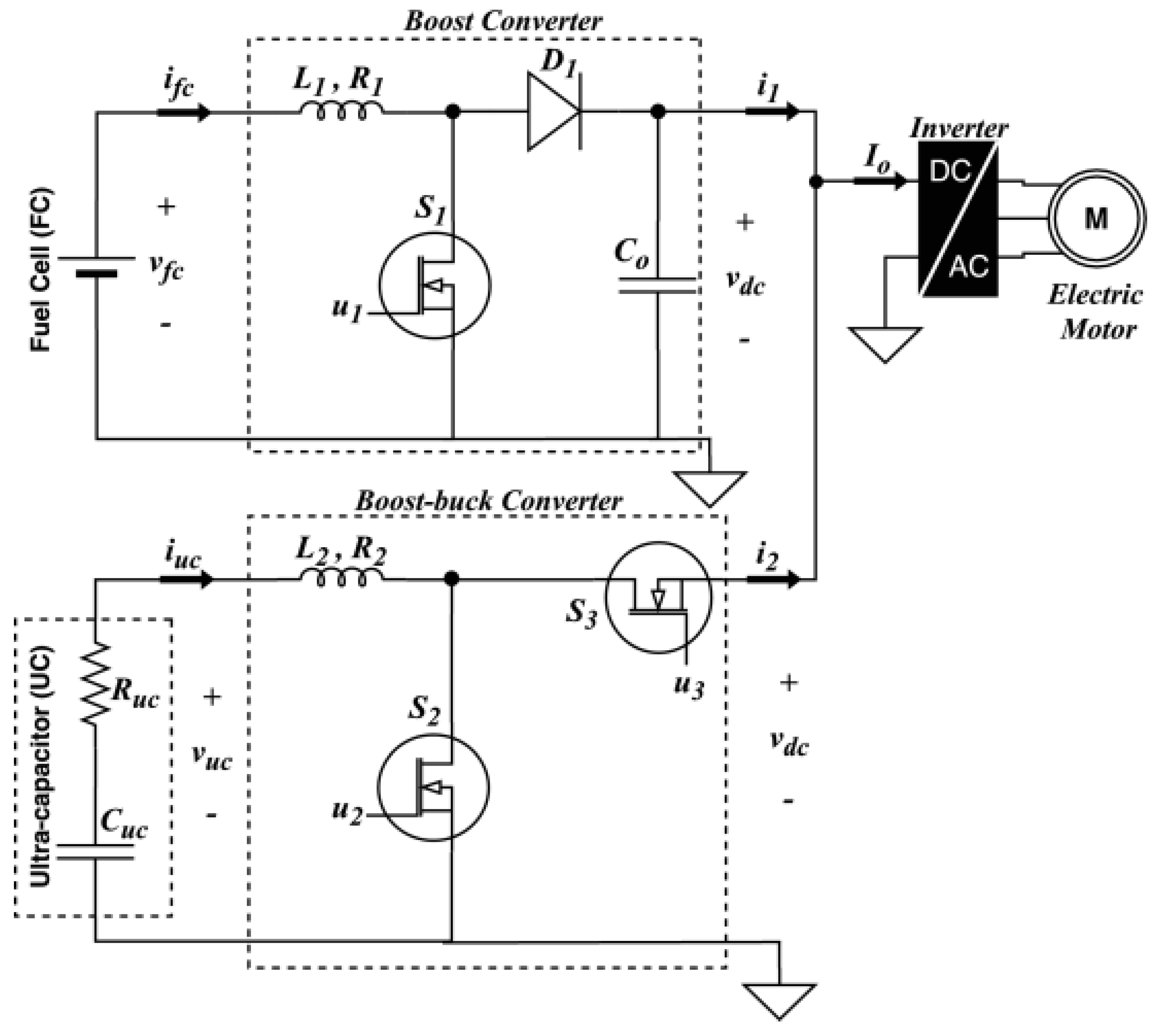
Figure 1. Power stage schematic of the HEV [5].
Energies 13 05587 g001
Figure 2. Equivalent circuit of a supercapacitor [33].
Energies 13 05587 g002
Figure 3. The power distribution strategy of the HEV.
Energies 13 05587 g003
Figure 4. Current tracking using the backstepping-based adaptive controller.
Energies 13 05587 g004
Figure 5. Time responses of inputs for the backstepping-based adaptive controller.
Energies 13 05587 g005
Figure 6. Current tracking using the Lyapunov-based adaptive controller.
Energies 13 05587 g006
Figure 7. Time responses of inputs for the Lyapunov-based adaptive controller.
Energies 13 05587 g007
Figure 8. Current tracking error comparison.
Energies 13 05587 g008
Figure 9. DC Bus voltage tracking comparison.
Energies 13 05587 g009
Figure 10. Hardware in the loop (HIL) setup.
Energies 13 05587 g010
Figure 11. DC bus voltage.
Energies 13 05587 g011
Figure 12. Fuel cell current.
Energies 13 05587 g012
Figure 13. Supercapacitor current.
Energies 13 05587 g013
Publisher’s Note: MDPI stays neutral with regard to jurisdictional claims in published maps and institutional affiliations.