Mechanisms and Applications of Pressure Relief by Roof Cutting of a Deep-Buried Roadway near Goafs


Abstract
:1. Introduction
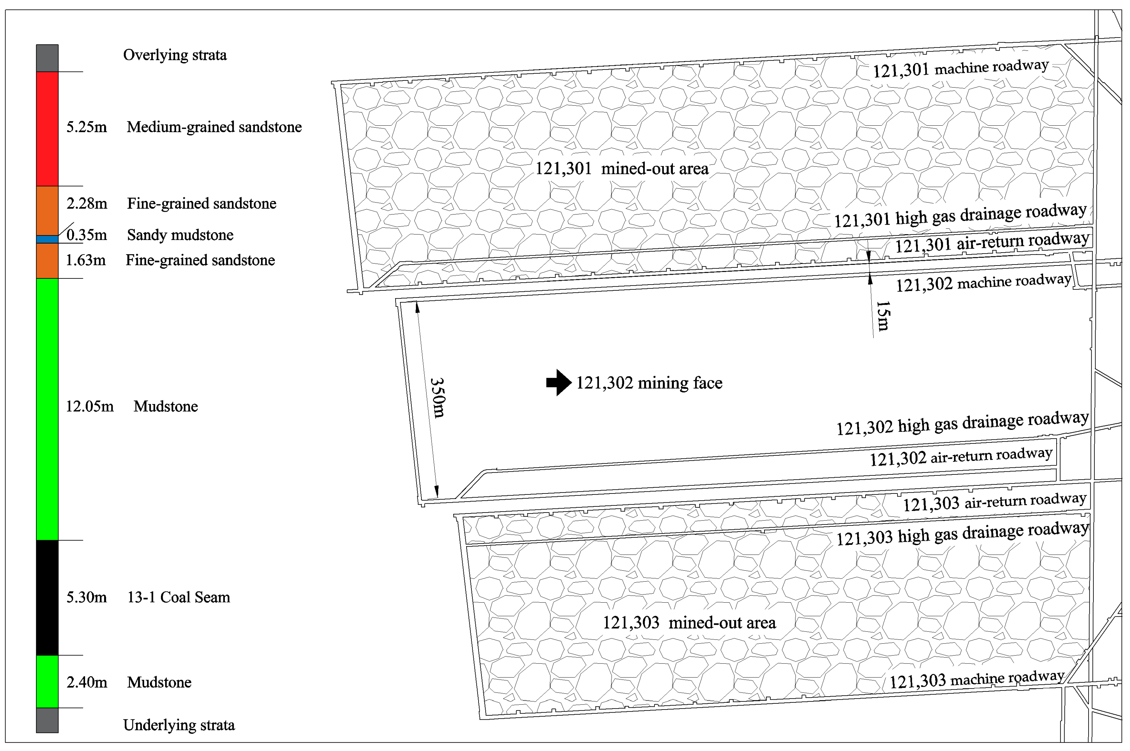
2. Background
3. Physical Simulation Experiment of Pressure Relief by Roof Cutting in an RNG
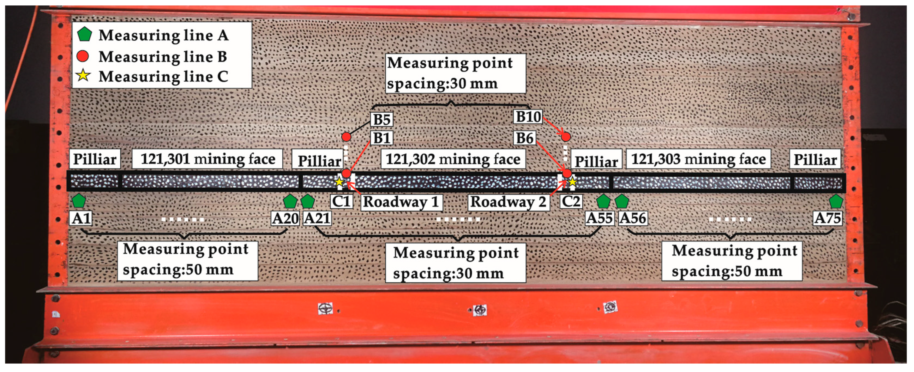
3.1. Physical Simulation Model
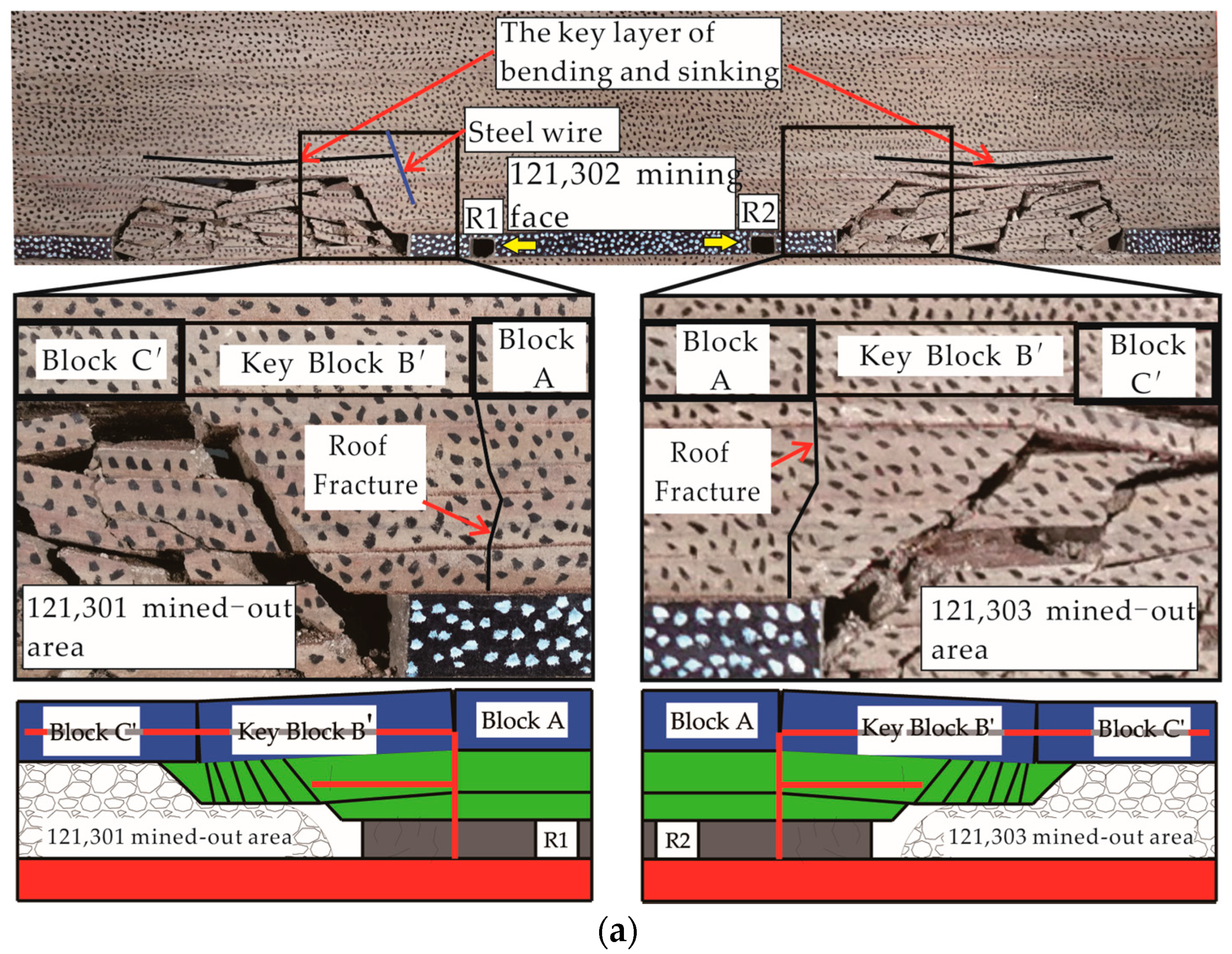
3.2. Overlying Strata Migration Law of the RNG
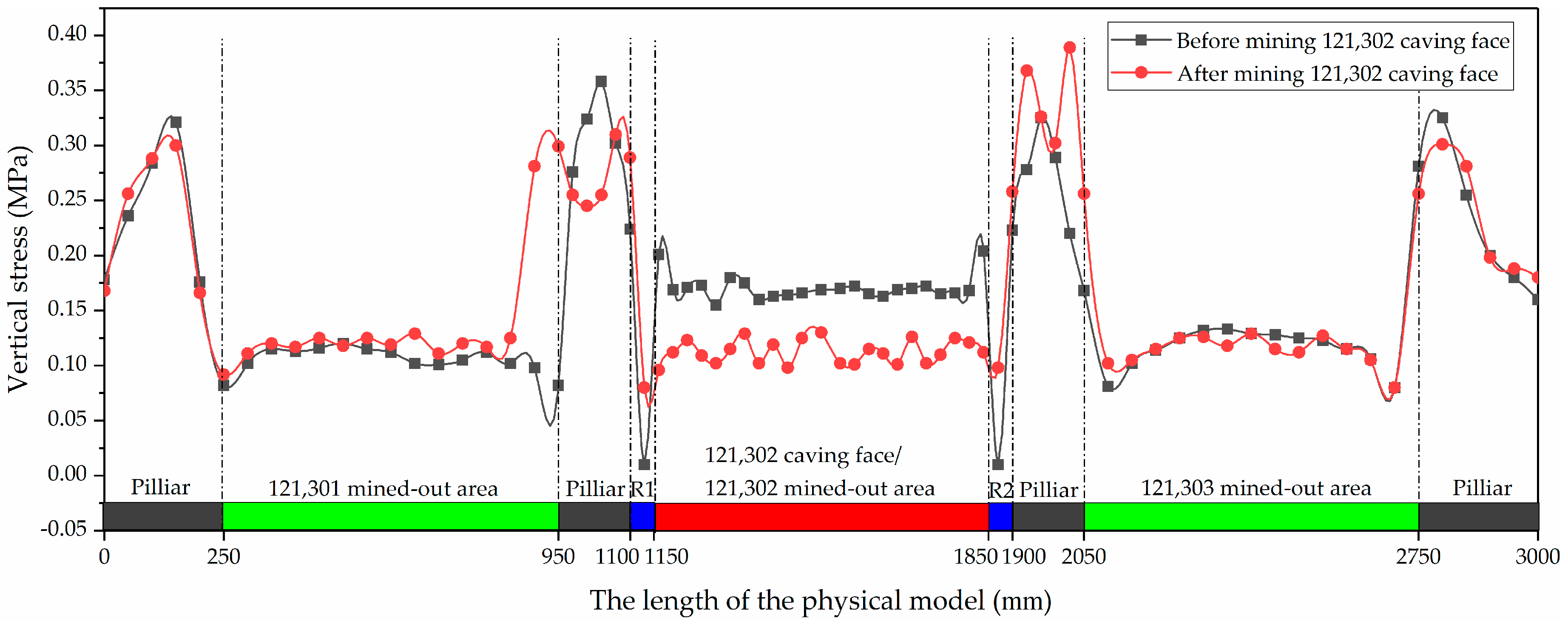
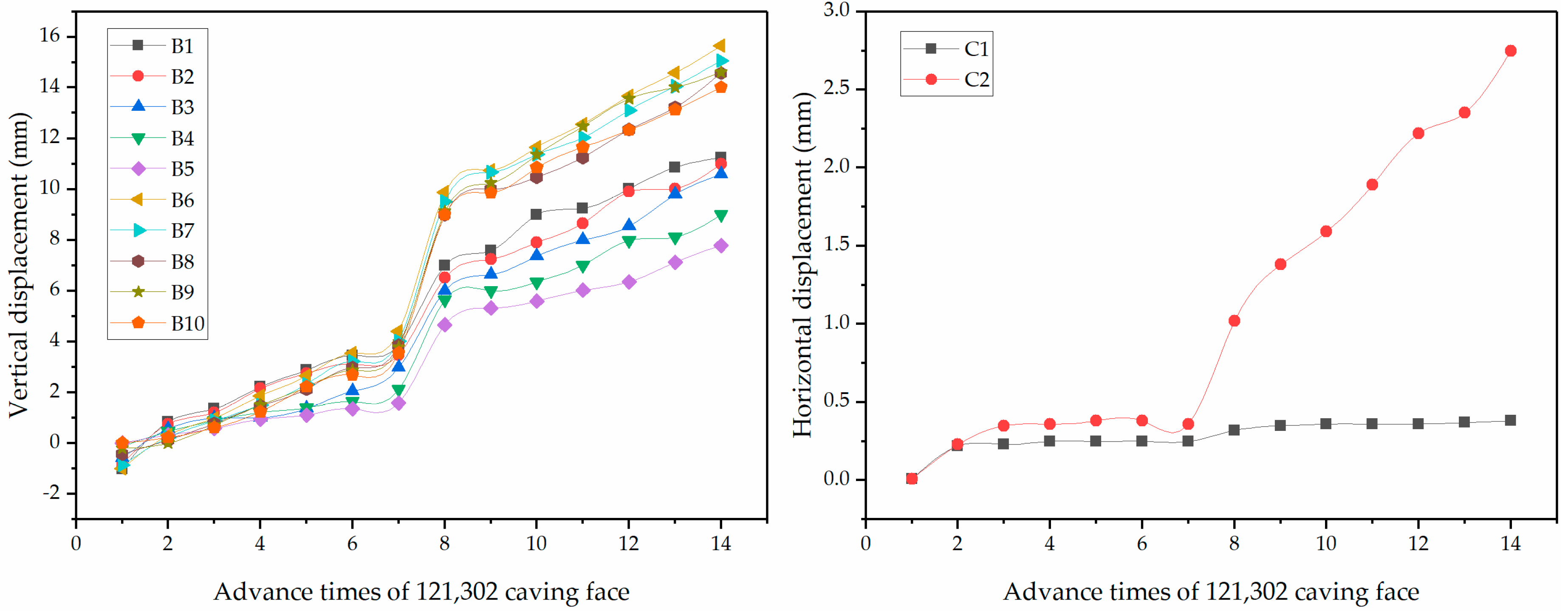
3.3. Analysis of Monitoring Results of Physical Simulation
4. Theoretical Analysis of Pressure Relief by Roof Cutting in the RNG
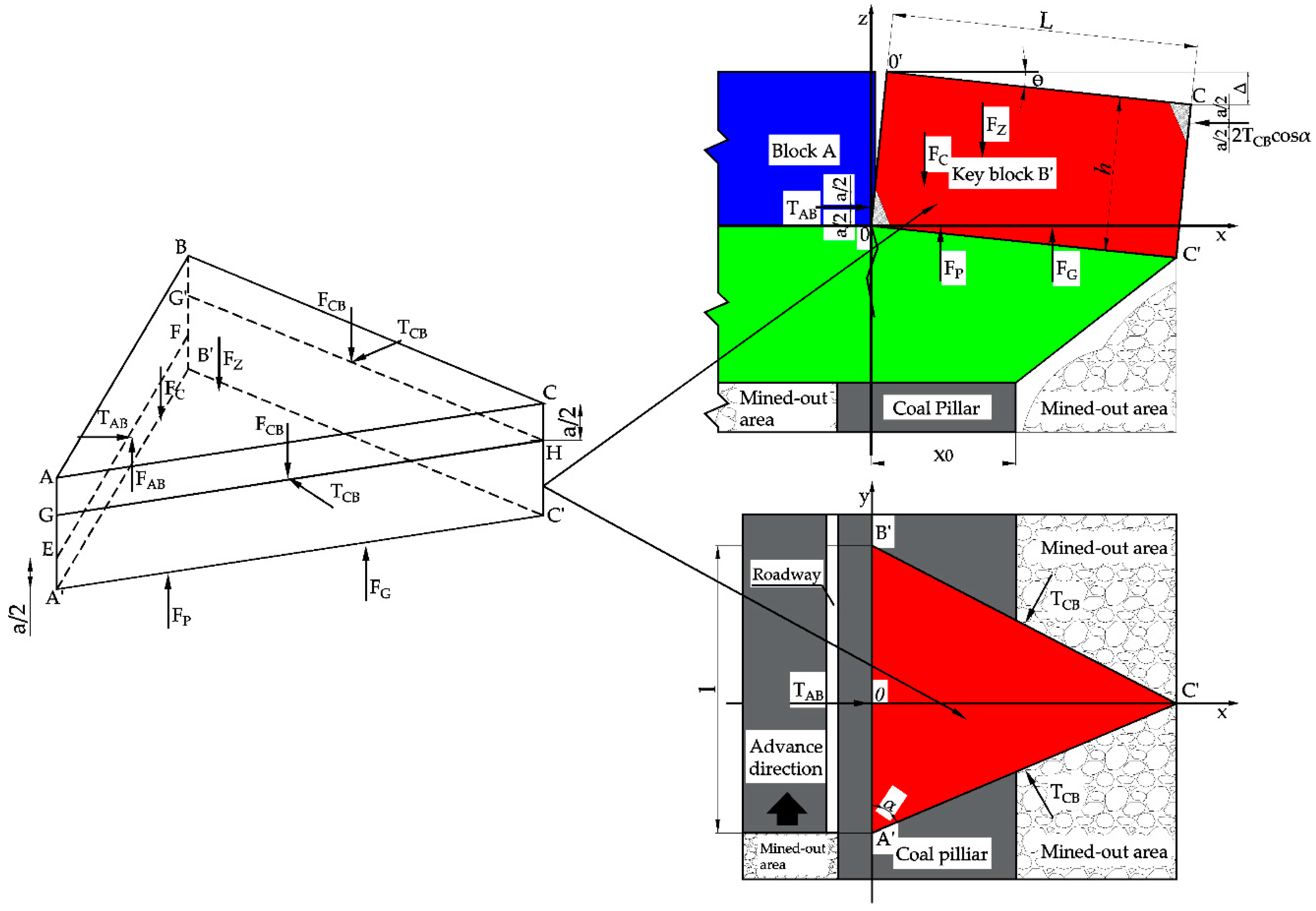
4.1. Mechanical Model of KBB’
- (1)
- At the front and rear, rock block C exerts equal forces on KBB’. FCB is the vertical shear of block C to KBB’ and TCB is the horizontal thrust of block C to KBB’. The acting point is located at the midpoint of GH and G’H, and the height direction CH is a/2. Additionally, “a” is the length of occlusal contact between blocks;
- (2)
- The vertical shear force and horizontal thrust of rock block A to KBB are denoted as FAB and TAB, respectively, which act on the midpoint of EF, and the height is at a/2, EF is the shaft of KBB’;
- (3)
- Fc is the mining pressure caused by the mining face, FP is the supporting force of the coal pillar, FG is the supporting force of the gangue in the goaf, and FZ is the self-coincidence force of KBB’ and the upper weak rock formation;
- (4)
- ∠CAB = ∠ABC = α, where θ is the turning angle of KBB’;
- (5)
- x0 is the break position of KBB:where λ is the lateral pressure coefficient; c0 is the cohesion of the coal seam (MPa); M is the thickness of the coal seam (m); φ0 is the internal friction angle (°); H is the buried depth of the working face (m); γ is the overlying strata bulk density (kN/m3); px is the support resistance of the roadside; and k is the stress concentration coefficient;
- (6)
- l is the length of KBB’ when following the forward face direction; L is the fracture size of KBB’ when following the inclined direction of the caving face; and L is when the key layer period collapses, as calculated by Formula (2):where S is the caving face length (m).
4.2. Force Analysis of Key Block B’ on Side Roof of Mined-Out Area of the RNG
- Mining pressure Fc is caused by the mining face:In Formula (3), fc is the mining stress caused by mining (MPa):where Kd is the superimposed support stress concentration factor, generally taken as between 2 and 5.
- Supporting force of the coal and rock masses in the lower part of key block B’:
- (1)
- Supporting force Fp of the coal pillar:where fp is the strength of the coal pillar (MPa). Owing to the effect of high crustal stress in deep mines, the coal pillar under KBB’ is generally at the stage of residual strength after a peak, and, at this time, the coal pillar strength iswhere ξ is the coal post-peak friction angle (°) and R′c is the coal post-peak residual strength (MPa).
- (2)
- Supporting force FG of gangue in a goaf:where fg is the supporting force produced by gangue in a goaf (MPa).where Kg is the support coefficient of the caving gangue (MPa/m); S0 is the overall subsidence of KBB’ (m); η is recovery rate of the caving face; KM is the crushing expansion coefficient of coal; and KZ is the crushing expansion coefficient of caving gangue.
- Horizontal thrust of block A and C′ to KBB’: According to Figure 6, let ∑MO′ = 0, thenwhere Rfc, Rfp, and Rfc are moments of FC, FP, and FG to EF, respectively:In Formula (9), a is the length of occlusal contact between blocks A, C’, and KBB’, and a = 1/2 (h − sinθ·L/2); Δ is the pivotal subsidence of KBB’, where Δ = Lsinθ; Fz is the KBB’ self-weight and its load, where Fz = 0.5lLγzhz; and the horizontal thrusts of blocks A and C’ to KBB’ are the following:
- Vertical forces of blocks A and C’ to KBB’: Considering Figure 6, let ∑MEF = 0, thenThe resultant force in the vertical direction is 0, namelyThe vertical forces of blocks A and C’ to KBB’ are the following:
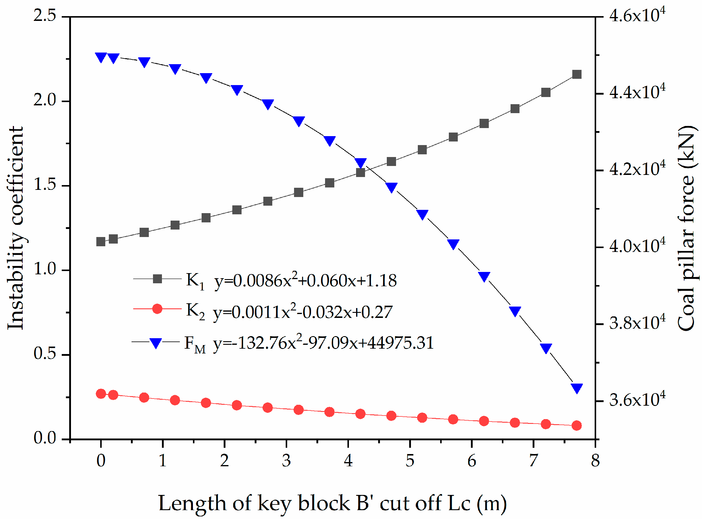
4.3. Research on the Effect of Roof Cutting on the Stability of KBB’ and the Force of the Coal Pillar
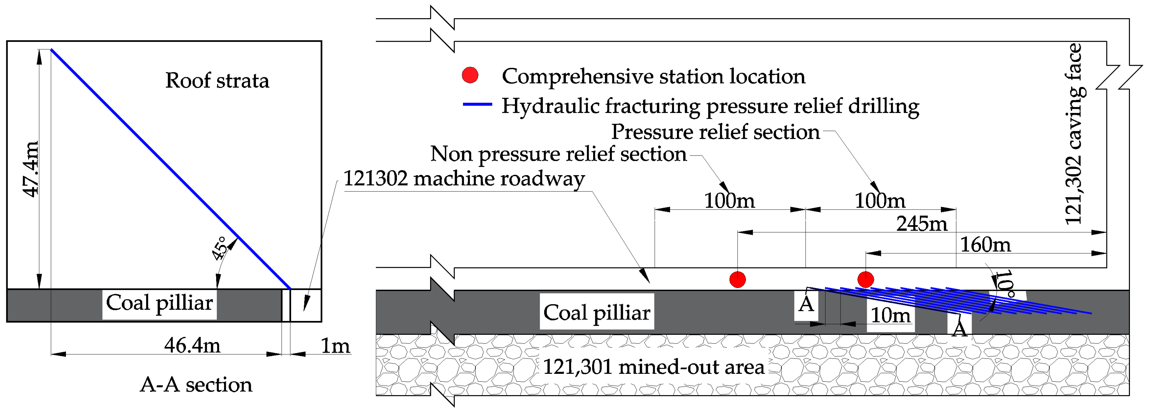
5. Engineering Verification
6. Discussion
7. Conclusions
- (1)
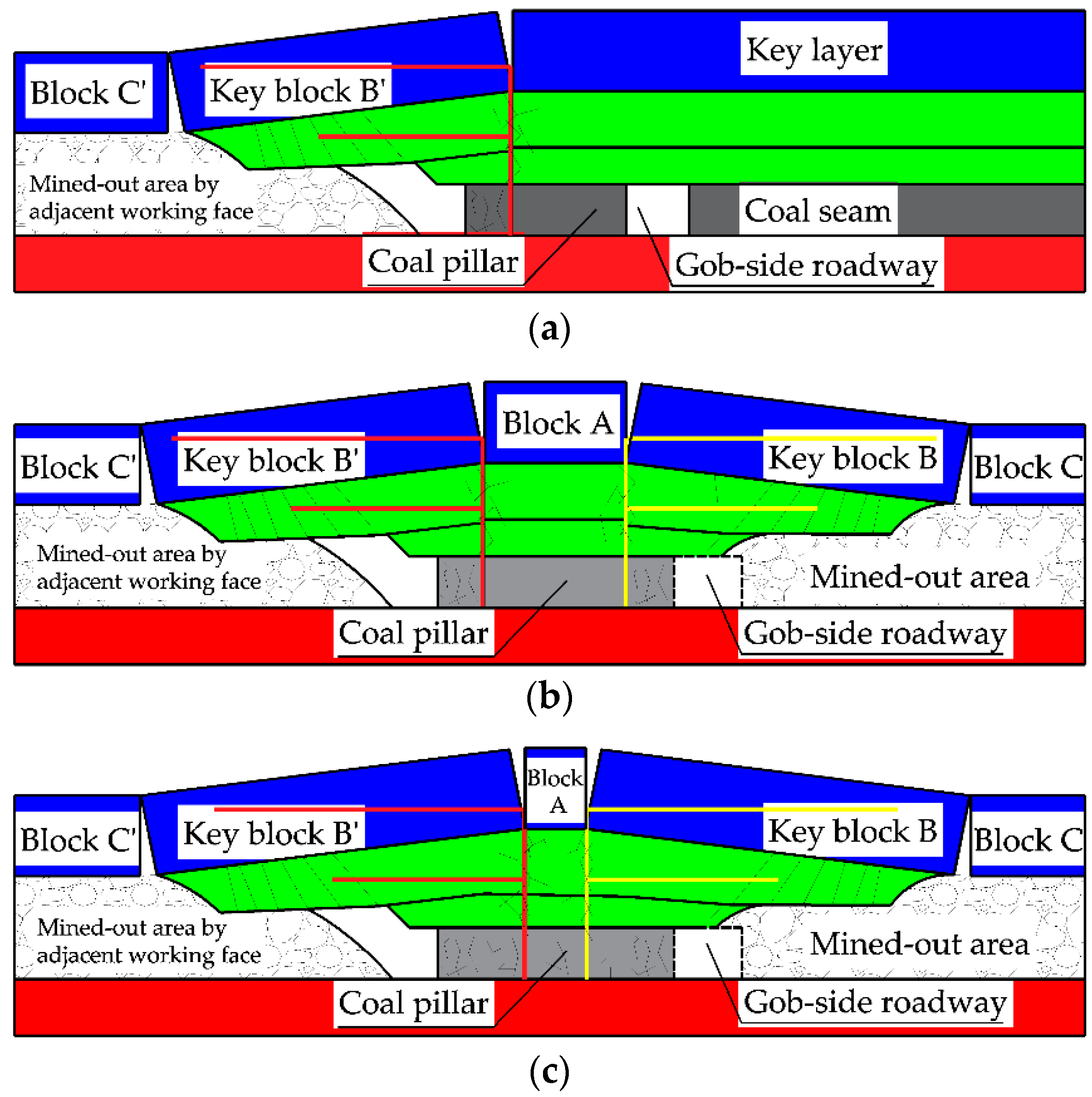
- The overlying rock structure of an RNG will eventually become a double short-arm “F”-type hanging roof structure, and the high-ground stress environment in deep mining conditions makes roof fractures shift to the deep part of coal pillars, which in turn leads to the instability of the double short-arm “F” structure. The superposition effect of the structure is the main cause of coal pillar expansion failure.
- (2)
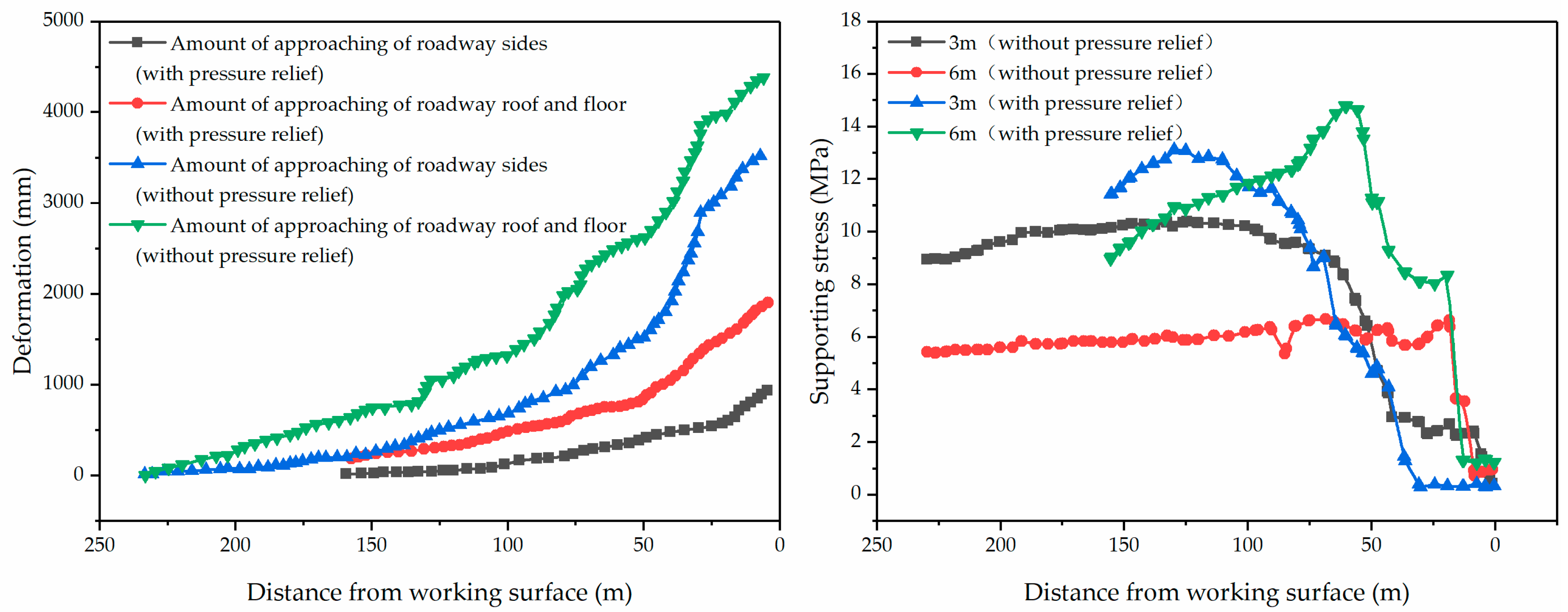
- Through the analysis of the physical similarity simulation model of surface displacement and stress data, it has been shown that manual roof cutting can reduce the vertical and horizontal approaches of a roadway and transfer the peak stress to the goaf, such that the coal pillar features a lower overall stress level.
- (3)
- The mechanism of pressure relief by cutting the roof of an RNG in a deep coal mine suggests the following: on the one hand, manual roof cutting can reduce the stress transfer path along the roof of a roadway and the overlying rock in the mined-out area, and then weaken the superimposed effect of the double “F” structure; on the other hand, the roof cut induces a new fracture in the roof, and the sliding deformation along the fracture line releases greater stress. At the same time, the cut roof can better fill the goaf and change the stress distribution ratio between the goaf and the coal pillar, thereby improving the stress state of the coal pillars and reducing roadway deformation.
- (4)
- The mechanical model of KBB was established, and the stability criterion for KBB was obtained. The results show that the stability of KBB becomes worse with the increase in mining depth. Under the existing engineering conditions, with the increase in the roof cutting length, KBB is more prone to slippage and instability, but the coal pillar force Fm decays as a quadratic function with the increase in the cutting roof length. When cutting KBB along the coal pillar, the force of the coal pillar decreases by 19.14%.
- (5)
- The field observation results show that the support stress of the coal pillar can be transferred to the side of the goaf via roof cutting, and this reduced the deformation of the roadway by more than 50% when compared with the uncut roadway section.
- (6)
- How to ensure the safety of roof cutting and pressure relief was a key issue, so the safety factor was a very important factor. However, this paper was more inclined to analyze the mechanisms of roof cutting and pressure relief, and did not propose a safety factor, which will be studied as a key point in the follow-up research.
Author Contributions
Funding
Conflicts of Interest
References
- Bai, J.B.; Wang, X.Y.; Hou, C.J. Research on technology of surrounding rock stability of soft rock roadway in high stress area. In Proceedings of the International Symposium on Safety Science and Technology, Jiaozuo, China, 16–19 April 2007. [Google Scholar]
- Yang, R.S.; Li, Y.L.; Guo, D.M.; Yao, L.; Yang, T.M.; Li, T.T. Failure mechanism and control technology of water-immersed roadway in high-stress and soft rock in a deep mine. Int. J. Min. Sci. Technol. 2017, 27, 245–252. [Google Scholar] [CrossRef]
- Chen, W.X.; He, X.Q.; Mitri, H.S.; Nie, B.S. Roadway stability analysis in a deep coal mine. In Proceedings of the International Young Scholars Symposium on Rock Mechanics, Beijing, China, 28 April–2 May 2008. [Google Scholar]
- Xie, H.P.; Gao, M.Z.; Zhang, R.; Peng, G.Y.; Wang, W.Y.; Li, A.Q. Study on the Mechanical Properties and Mechanical Response of Coal Mining at 1000m or Deeper. Rock Mech. Rock Eng. 2019, 52, 1475–1490. [Google Scholar] [CrossRef]
- Yuan, Y.; Wang, W.J.; Li, S.Q.; Zhu, Y.J. Failure Mechanism for Surrounding Rock of Deep Circular Roadway in Coal Mine Based on Mining-Induced Plastic Zone. Adv. Civ. Eng. 2018, 2018, 1835381. [Google Scholar] [CrossRef]
- Sun, Y.T.; Li, G.C.; Zhang, J.F.; Qian, D.Y. Stability Control for the Rheological Roadway by a Novel High-Efficiency Jet Grouting Technique in Deep Underground Coal Mines. Sustainability 2019, 11, 6494. [Google Scholar] [CrossRef] [Green Version]
- Yang, S.Q.; Chen, M.; Jing, H.W.; Chen, K.F.; Meng, B. A case study on large deformation failure mechanism of deep soft rock roadway in Xin’An coal mine, China. Eng. Geol. 2017, 217, 89–101. [Google Scholar] [CrossRef]
- Wang, Q.; Pan, R.; Jiang, B.; Li, S.C.; He, M.C.; Sun, H.B.; Wang, L.; Qin, Q.; Yu, H.C.; Luan, Y.C. Study on failure mechanism of roadway with soft rock in deep coal mine and confined concrete support system. Eng. Fail. Anal. 2017, 81, 155–177. [Google Scholar] [CrossRef]
- Shreedharan, S.; Kulatilake, P.H.S.W. Discontinuum-Equivalent Continuum Analysis of the Stability of Tunnels in a Deep Coal Mine Using the Distinct Element Method. Rock Mech. Rock Eng. 2016, 49, 1903–1922. [Google Scholar] [CrossRef]
- Jiang, B.Y.; Wang, L.G.; Lu, Y.L.; Gu, S.T.; Sun, X.K. Failure Mechanism Analysis and Support Design for Deep Composite Soft Rock Roadway: A Case Study of the Yangcheng Coal Mine in China. Shock Vib. 2015, 2015, 452479. [Google Scholar] [CrossRef]
- Xu, M.F.; Wu, S.C.; Gao, Y.T.; Ma, J.; Wu, Q.L. Analytical elastic stress solution and plastic zone estimation for a pressure relief circular tunnel using complex variable methods. Tunn. Undergr. Space Technol. 2019, 84, 381–398. [Google Scholar] [CrossRef]
- Zhai, X.X.; Huang, G.S.; Chen, C.Y.; Li, R.B. Combined Supporting Technology with Bolt-Grouting and Floor Pressure-Relief for Deep Chamber: An Underground Coal Mine Case Study. Energies 2018, 11, 67. [Google Scholar] [CrossRef] [Green Version]
- Seo, S.Y.; Ha, H. A Numerical Study on the Effect of Pressure Relief in a High-Speed Railway Tunnel. Road Rail Infrastr. 2018, 1515–1524. [Google Scholar] [CrossRef]
- Han, C.L.; Zhang, N.; Li, B.Y.; Si, G.Y.; Zheng, X.G. Pressure relief and structure stability mechanism of hard roof for gob-side entry retaining. J. Cent. South Univ. 2015, 22, 4445–4455. [Google Scholar] [CrossRef]
- Wang, Y.J.; Yang, J.; He, M.C.; Tian, X.C.; Liu, J.N.; Xue, H.J.; Huang, R.F. Test of a liquid directional roof-cutting technology for pressure-relief entry retaining mining. J. Geophys. Eng. 2019, 16, 620–638. [Google Scholar] [CrossRef] [Green Version]
- Zhang, S.C.; Li, Y.Y.; Shen, B.T.; Sun, X.Z.; Gao, L.Q. Effective evaluation of pressure relief drilling for reducing rock bursts and its application in underground coal mines. Int. J. Rock Mech. Min. 2019, 114, 7–16. [Google Scholar] [CrossRef]
- Song, D.Z.; Wang, E.Y.; Xu, J.K.; Liu, X.F.; Shen, R.X.; Xu, W.Q. Numerical simulation of pressure relief in hard coal seam by water jet cutting. Geomech. Eng. 2015, 8, 495–510. [Google Scholar] [CrossRef]
- Zhang, S.G.; Chen, L.; Jia, H.Y. The Surrounding Rock of Deep Borehole Pressure Relief and Let the Pressure Bolt Coupling Analysis. Appl. Mech. Mater. 2014, 446–447, 1421–1424. [Google Scholar] [CrossRef]
- Liu, C.K.; Ren, J.X.; Zhang, K.; Chen, S.J. Numerical studies on surrounding rock deformation controlled by pressure relief groove in deep roadway. IOP Conf. Ser. Earth Environ. Sci. 2017, 64, 012029. [Google Scholar] [CrossRef] [Green Version]
- Liu, J.W.; Liu, C.Y.; Li, X.H. Determination of fracture location of double-sided directional fracturing pressure relief for hard roof of large upper goaf-side coal pillars. Energy Explor. Exploit. 2020, 38, 111–136. [Google Scholar] [CrossRef] [Green Version]
- Wang, Y.J.; He, M.C.; Yang, J.; Wang, Q.; Liu, J.N.; Tian, X.C.; Gao, Y.B. Case study on pressure-relief mining technology without advance tunneling and coal pillars in longwall mining. Tunn. Undergr. Space Technol. 2020, 97, 103236. [Google Scholar] [CrossRef]
- Liu, H.; Dai, J.; Jiang, J.Q.; Wang, P.; Yang, J.Q. Analysis of Overburden Structure and Pressure-Relief Effect of Hard Roof Blasting and Cutting. Adv. Civ. Eng. 2019, 2019, 1354652. [Google Scholar] [CrossRef] [Green Version]
- Liu, H.T.; Guo, L.F.; Cao, G.M.; Zhao, X.D.; Wang, P.F.; Huo, T.H.; Yang, G.; Hao, C.; Wang, Q. Comprehensive Study of Strata Movement Behavior in Mining a Longwall Top Coal Caving Panel of a Composite Coal Seam with Partings. Appl. Sci. 2020, 10, 5311. [Google Scholar] [CrossRef]
- Fang, F.; Shu, C.; Wang, H.T. Physical simulation of upper protective coal layer mining with different coal seam inclinations. Energy Sci. Eng. 2020, 8, 3103–3116. [Google Scholar] [CrossRef]
- Xu, Z.H.; Li, Q.S.; Li, X.B. Overburden Migration and Failure Characteristics in Mining Shallow Buried Coal Seam with Thick Loose Layer. Adv. Mater. Sci. Eng. 2020, 2020, 9024751. [Google Scholar] [CrossRef]
- Zhang, D.S.; Miao, X.X.; Ma, L.Q.; Feng, G.M. Technique of gob-side entry retaining with entry-in packing in fully-mechanized coalface with top-coal caving. In Proceedings of the 5th International Symposium on Mining Science and Technology, Xuzhou, China, 20–22 October 2004. [Google Scholar]
- Bai, J.B.; Shen, W.L.; Guo, G.L.; Wang, X.Y.; Yu, Y. Roof Deformation, Failure Characteristics, and Preventive Techniques of Gob-Side Entry Driving Heading Adjacent to the Advancing Working Face. Rock Mech. Rock Eng. 2015, 48, 2447–2458. [Google Scholar] [CrossRef]
- Linming, D.; Hu, H. Study of OX-FT spatial structure evolution of overlying strata in coal mines. Chin. J. Rock Mech. Eng. 2012, 31, 453–460. [Google Scholar]
- Xie, J.L.; Xu, J.L.; Wang, F. Mining-induced stress distribution of the working face in a kilometer-deep coal mine-a case study in Tangshan coal mine-a case study in Tangshan coal mine. J. Geophys. Eng. 2018, 15, 2060–2070. [Google Scholar] [CrossRef] [Green Version]
- Chen, Y.L.; Lu, A.H.; Mao, X.B.; Li, M.; Zhang, L.Y. Nonlinear Dynamics Mechanism of Rock Burst Induced by the Instability of the Layer-Crack Plate Structure in the Coal Wall in Deep Coal Mining. Shock Vib. 2017, 2017, 4051967. [Google Scholar] [CrossRef] [Green Version]
- Szurgacz, D.; Brodny, J. Tests of Geometry of the Powered Roof Support Section. Energies 2019, 12, 3945. [Google Scholar] [CrossRef] [Green Version]
- Szurgacz, D.; Brodny, J. Adapting the Powered Roof Support to Diverse Mining and Geological Conditions. Energies 2020, 13, 405. [Google Scholar] [CrossRef] [Green Version]
- He, M.C.; Gao, Y.B.; Yang, J.; Gong, W.L. An Innovative Approach for Gob-Side Entry Retaining in Thick Coal Seam Longwall Mining. Energies 2017, 10, 1785. [Google Scholar] [CrossRef] [Green Version]


| Rock Character | Density/kg∙m−3 | Compressive Strength/MPa |
|---|---|---|
| Medium-grained sandstone (MGS) | 2475 | 42.5 |
| Fine-grained sandstone (FGS) | 2350 | 44.3 |
| Sandy mudstone (SM) | 2300 | 32.5 |
| Mudstone | 2250 | 28.2 |
| Coal | 1450 | 13.5 |
| Lithology | Thickness (cm) | Proportion | Weight of Each Layer (kg) | Amount of Sand (kg) | Amount of Lime (kg) | Amount of Gypsum (kg) | Amount of Water (kg) |
|---|---|---|---|---|---|---|---|
| Overlying strata | 20 | 773 | 160.0 | 140.0 | 14.0 | 6.0 | 20.0 |
| Mudstone | 15 | 537 | 120.0 | 100.0 | 6.0 | 14.0 | 15.0 |
| MGS | 5 | 337 | 44.0 | 33.0 | 3.3 | 7.7 | 5.5 |
| FGS | 2 | 355 | 16.7 | 12.5 | 2.1 | 2.1 | 2.1 |
| SM | 1 | 455 | 8.2 | 6.5 | 0.8 | 0.8 | 1.0 |
| FGS | 2 | 355 | 16.7 | 12.5 | 2.1 | 2.1 | 2.1 |
| Mudstone | 12 | 537 | 96.0 | 80.0 | 4.8 | 11.2 | 12.0 |
| 13-1 coal | 5 | 573 | 25.8 | 21.5 | 3.0 | 1.3 | 3.2 |
| Mudstone | 3 | 537 | 24.0 | 20.0 | 1.2 | 2.8 | 3.0 |
| FGS | 5 | 355 | 41.8 | 31.3 | 5.2 | 5.2 | 5.2 |
| SM | 10 | 455 | 81.8 | 65.4 | 8.2 | 8.2 | 10.2 |
| Underlying strata | 20 | 773 | 160.0 | 140.0 | 14.0 | 6.0 | 20 |
| Contrast Item | Reduction Percentage of Roadway Deformation | Reduction Percentage of Coal Pillar Stress | |
|---|---|---|---|
| Research Methods | |||
| Physical simulation | 33.4% | 21% | |
| Theoretical analysis | —— | 19.14% | |
| Field observation | ≥50% | —— | |
Publisher’s Note: MDPI stays neutral with regard to jurisdictional claims in published maps and institutional affiliations. |
© 2020 by the authors. Licensee MDPI, Basel, Switzerland. This article is an open access article distributed under the terms and conditions of the Creative Commons Attribution (CC BY) license (http://creativecommons.org/licenses/by/4.0/).
Share and Cite
Li, P.; Lai, X.; Gong, P.; Su, C.; Suo, Y. Mechanisms and Applications of Pressure Relief by Roof Cutting of a Deep-Buried Roadway near Goafs. Energies 2020, 13, 5732. https://doi.org/10.3390/en13215732
Li P, Lai X, Gong P, Su C, Suo Y. Mechanisms and Applications of Pressure Relief by Roof Cutting of a Deep-Buried Roadway near Goafs. Energies. 2020; 13(21):5732. https://doi.org/10.3390/en13215732
Chicago/Turabian StyleLi, Peng, Xingping Lai, Peilin Gong, Chao Su, and Yonglu Suo. 2020. "Mechanisms and Applications of Pressure Relief by Roof Cutting of a Deep-Buried Roadway near Goafs" Energies 13, no. 21: 5732. https://doi.org/10.3390/en13215732