Article

Modeling of Working Machines Synergy in the Process of the Hybrid Electric Vehicle Acceleration

by
Konrad Prajwowski
,
Wawrzyniec Golebiewski
*,
Maciej Lisowski
,
Karol F. Abramek
and
Dominik Galdynski
Department of Automotive Engineering, Faculty of Mechanical Engineering and Mechatronics, West Pomeranian University of Technology, Piastow Avenue 19, 70-310 Szczecin, Poland
*
Author to whom correspondence should be addressed.
Energies 2020, 13(21), 5818; https://doi.org/10.3390/en13215818
Submission received: 7 October 2020 / Revised: 2 November 2020 / Accepted: 3 November 2020 / Published: 6 November 2020

Abstract

:
There are many different mathematical models that can be used to describe relations between energy machines in the power-split hybrid drive system. Usually, they are created based on simulations or measurements in bench (laboratory) conditions. In that sense, however, these are the idealized conditions. It is not known how the internal combustion engine and electrical machines work in real road conditions, especially during acceleration. This motivated the authors to set the goal of solving this research problem. The solution was to implement and develop the model predictive control (MPC) method for driving modes (electric, normal) of a hybrid electric vehicle equipped with a power-split drive system. According to the adopted mathematical model, after determining the type of model and its structure, the measurements were performed. There were carried out as road tests in two driving modes of the hybrid electric vehicle: electric and normal. The measurements focused on the internal combustion engine and electrical machines parameters (torque, rotational speed and power), state of charge of electrochemical accumulator system and equivalent fuel consumption (expressed as a cost function). The operating parameters of the internal combustion engine and electric machines during hybrid electric vehicle acceleration assume the maximum values in the entire range (corresponding to the set vehicle speeds). The process of the hybrid electric vehicle acceleration from 0 to 47 km/h in the electric mode lasted for 12 s and was transferred into the equivalent fuel consumption value of 5.03 g. The acceleration of the hybrid electric vehicle from 0 to 47 km/h in the normal mode lasted 4.5 s and was transferred to the value of 4.23 g. The hybrid electric vehicle acceleration from 0 to 90 km/h in the normal mode lasted 11 s and corresponded to the cost function value of 26.43 g. The presented results show how the fundamental importance of the hybrid electric vehicle acceleration process with a fully depressed gas pedal is (in these conditions the selected driving mode is a little importance).

Graphical Abstract

1. Introduction

The effective synergy of the internal combustion engine and electrical machines, as well as the use of energy recovery during recuperative braking, allows the hybrid electric vehicle (HEV) to reduce its fuel consumption. Another undoubted advantage associated with the greater energy efficiency is the lower level of toxic emissions [1,2]. The improvement of economic and ecological indicators depends on an effective energy management system. To date, various models of power flow management strategies have been used in hybrid electric vehicles. Early energy management systems were based on the predicted operating conditions of the hybrid electric vehicle drive system (heuristic hypotheses). Control strategy of the internal combustion engine and electric engine operation assumed the use of electric mode from the state of the stationary car to the given vehicle speed. Above this speed, the torque of the electric motor decreased, and the shortage of torque, to overcome the resistance to movement, was gratified by the internal combustion engine [3,4]. The priority of the energy management system was to minimize the performance indicator described as the mass of fuel consumed in time [5,6,7].
Barsali et al. proposed statistical optimization as an energy management strategy based on minimizing the fuel consumption [5]. This approach did not require the detailed knowledge of the actual power demand, but only the knowledge of its average value. The accuracy of the method used resulted in its development in an energy management strategy for the electric power system ensuring reduction of fuel consumption and toxic emissions, based on dynamic programming (DP) [8,9,10,11]. The concept presented by Lin et al. [10] was based on stochastic-dynamic programming (SDP). The authors’ approach assumed a deterministic vehicle model, but also a driver’s stochastic power demand. The optimization was not based on a specific driving cycle but on the basis of the likelihood of demand for specific power in general driving conditions. Due to the considerable computational time requirements, the numerical optimization methods have been replaced by analytical optimization methods [3,12]. The method limiting the calculation expenditure assumed the introduction of the Hamiltonian function. The energy management strategy also used the theory of optimal control described by the Euler–Lagrange equation.
A different approach to the topic of energy management in hybrid vehicles could be found in the works of Paganelli et al. [13,14]. They present algorithms for the equivalent consumption minimization strategy (ECMS) for both hybrid drive systems and hybrid electric vehicles equipped with fuel cells. The strategy for controlling the value of equivalent fuel consumption was also used in the literature [15,16] and was presented as a cost function defined in the form of the sum of fuel and electricity consumption. This value, however, depended on a priori information on driving conditions or on the conditions of the adopted driving cycle. The modification of the ECMS optimization algorithm used for power-split hybrid systems was undertaken by Liu and Peng [17]. They used the SDP and ECMS strategy and the algorithms they used allowed them to improve the dynamic properties of the hybrid electric vehicle while reducing fuel consumption. They also built an automatic model of the power-split hybrid system in which the applied methodology proposed the automatic generation of dynamic systems equations. The algorithms show the cooperation of the internal combustion engine with electric machines, ensuring lower fuel consumption (as part of experiments according to a specific driving cycle) [18].
Another real-time algorithm used for decreasing the fuel consumption was the particle swarm optimization (PSO) [19,20,21,22,23,24]. This method has been applied in hybrid electric vehicles (HEVs) and plug-in HEVs [19,20]. The main goal of the algorithm was to optimize the control strategy in order to achieve the lowest fuel consumption. The development of the algorithm used by Hwang and Chen improved the fuel consumption by 9.4% in relation to the base control model [24].
Earlier Kim et al. [25] developed another energy management system in hybrid vehicles called the model predictive control (MPC). It was a strategy for optimal torque distribution for a parallel hybrid drive system. The cost function used in it was minimized on the basis of telemetric estimation of the vehicle speed. Borhan et al. [26] used the MPC in a power-split hybrid drive system equipped with an ultra-capacitor as the energy storage system. In parallel, Moura et al. [27] developed supervision to minimize the fuel consumption of a vehicle equipped with a series hybrid drive system by stochastic optimization of the control process using the Markov chain.
The MPC method was also used to determine the control inputs for economic driving (better fuel economy) of HEVs [28] and it depended largely on information from the management of Intelligent Transportation System (ITS). Yang and Zhu [29,30] developed the MPC system using linear quadratic tracking (LQT) consisting of controlling the power distribution of a power-split hybrid system to track the expected power demand set by a driver. The LQT controller minimized the cost function and at the same time maintained the battery level at the desired level.
An alternative development of the MPC strategy was the use of an energy management system known as nonlinear model predictive control (NMPC). The method used allowed an improvement in the amount of fuel consumption obtained in the NEDC cycle by 8.8% (compared to the factory control of the power-split hybrid system) [31].
The model of power-split hybrid systems was also presented by Cao, Peng and He. It was characterized by high accuracy; however, the created model was tested experimentally based on specific driving cycles, such as the new european driving cycle (NEDC) or the highway fuel economy driving schedule (HWYCOL) [32].
The above literature review brings the current state of knowledge related to the different mathematical models of the power-split hybrid drive system. They were created based on simulations or observations and measurements in bench (laboratory) conditions [17,18,29,30,31,32]. In the sense; however, these are idealized conditions. It is not known how the internal combustion engine and electrical machines work in real road conditions, especially during acceleration in various driving modes. It is not known whether the selection of the driving mode is of a significance importance during acceleration. It is also unknown in which driving mode the acceleration of the hybrid electric vehicle is more energy efficient. Those scientific considerations led the authors to set the goal of solving this research problem. The solution to the research problem was the implementation and development of the MPC method for driving modes (electric, normal) of a hybrid electric vehicle equipped with a power-split drive system. It was carried out in accordance with the research program, which assumed:
specification of the components assembled in the tests (experimental part);
creating a mathematical model of a power-split hybrid vehicle;
presentation of the results;
discussion of the results and conclusions.

2. Experimental Part

The experiments included the identification of the test object, a polygon stand and the test apparatus. The test object was a third generation Toyota Prius vehicle. The basic vehicle parameters are summarized in Table 1a,b [19,33].
The polygon stand was an asphalt road located outside the city. The operation parameters of the internal combustion engine and electric machines have been tested using the test equipment (Gutmann Mega Macs diagnostic program and Dynomet chassis dynamometer). The specific results of the given parameters were obtained in Section 4.

3. Model of a Power-Split Hybrid Drive System

A model of a power-split electric-combustion drive system is shown in Figure 1. It consists of the following components: traffic conditions (desired speed), driver, driving modes, gas pedal, powertrain controller, internal combustion engine, generator, electric motor, high voltage battery, inverter, planetary gear, main gear, wheels and current speed. The driver, who selects the operating mode of the system (electric, normal) and presses on the gas pedal which transfers into the power of the vehicle (the power demand is stochastic), is the variable controlling the hybrid system. The drive system controller receives signals from a series of sensors, which include, among others, gas pedal position sensors and wheel speed sensor, and monitors the operation of the vehicle with the implemented energy management system.

3.1. Torque Transmission Dynamics and Vehicle Movement

The third generation Toyota Prius vehicle is equipped with two planetary gears. The kinematic diagram of the system for the normal driving mode is shown in Figure 2. The torque generated by the internal combustion engine is transmitted to the yoke of the satellite wheels and then to the ring gear of the planetary gear.
After the transmission through the planetary gear, the torque, using the intermediate gear and main gear, drives the car’s axle shafts. The MG1 generator, connected to the sun gear, acts as a starter and is used to charge the battery while driving. The MG2 electric machine, connected to the sun gear of the second planetary gear (transferring torque to the ring gear by the immobilized satellite yoke) was designed to assist the internal combustion engine in generating power, but also to provide energy recovery during braking [33].
In order to implement the mathematical model describing the dynamic scheme of torque transmission in the power-split hybrid drive system, the following assumptions were made:
all shaft connections are rigid so there is no slippage between the drive components (no power loss);
the moments of inertia of the internal combustion engine and electric machines are related to the moments of inertia of the yokes of satellites, sun wheels and crown gear;
the moment of inertia of the main gear pinion is not taken into account;
only longitudinal forces acting on the vehicle during travel are taken into account.
The drive system model (Figure 2) for the normal driving mode is described by the following equations [33]:
(a)
Angular velocities:
ω C 1 = R 1 S 1 + R 1 ω R + S 1 S 1 + R 1 ω S 1
ω C 2 = R 2 S 2 + R 2 ω R + S 2 S 2 + R 2 ω S 2
The yoke of the satellites of the second planetary gear is locked, therefore ω C 2 = 0 .
0 = R 2 S 2 + R 2 ω R + S 2 S 2 + R 2 ω S 2
R 2 S 2 + R 2 ω R = S 2 S 2 + R 2 ω S 2
ω R = S 2 R 2 ω S 2
ω S 2 = ω M ,   ω C 1 = ω E ,   ω S 1 = ω G
ω R = S 2 R 2 ω M
ω E = R 1 S 1 + R 1 ω R + S 1 S 1 + R 1 ω G
ω E = R 1 S 1 + R 1 S 2 R 2 ω M + S 1 S 1 + R 1 ω G
ω M = R 2 S 2 ω R
ω G = ω E ( R 1 + S 1 ) S 1 + R 1 S 1 S 2 R 2 ω M
(b)
Mass moments of inertia and torques of the system:
J E ω E = T E F 1 ( R 1 + S 1 )
J G ω G = T G + F 1 S 1
J M ω M = T M F 2 S 2
J R ω R = F 1 R 1 + F 2 R 2 T R = R 1 R 1 + S 1 T E + R 2 S 2 T M T R
(c)
Vehicle inertia:
m v v e h = T R f d + T b r k r d 1 2 ρ A C d A f v v e h 2 m g ( f r cos α + sin α )
(d)
Vehicle speed:
v v e h = ω R r d f d
Using the equations from (1) to (17) with the above-mentioned assumptions (JR 0) the simplified version of the model is as follows:
[ J E + J G ( R 1 + S 1 S 1 ) 2 ] ω E [ J G R 1 S 2 ( R 1 + S 1 ) R 2 S 1 2 ] ω M = T E + T G ( R 1 + S 1 ) S 1
[ J E R 1 R 1 + S 1 ] ω E + [ J M R 2 S 2 m ( r d f d ) 2 S 2 R 2 ] ω M         = T E R 1 R 1 + S 1 + T M R 2 S 2 + T b r k f d + 1 2 ρ A C d A f S 2 2 ω M 2 r d 3 R 2 2 f d 3         m g r d f d ( f r cos α + sin α )
The drive system model for the electric mode is described by the following relationships [33]:
(a)
Angular velocities:
The first two relations are the same as the (1) and (2) but the yoke of the satellites of the first and second planetary gears is locked, so:
0 = R 1 S 1 + R 1 ω R + S 1 S 1 + R 1 ω S 1
ω S 1 = R 1 S 1 ω R
0 = R 2 S 2 + R 2 ω R + S 2 S 2 + R 2 ω S 2
S 2 S 2 + R 2 ω S 2 = R 2 S 2 + R 2 ω R
ω R = S 2 R 2 ω S 2
ω S 1 = ω G ,   ω S 2 = ω M
ω R = S 2 R 2 ω M
ω E = 0
ω G = R S 1 ω R = R S 1 S 2 R 2 ω M
(b)
Mass moments of inertia and torques of the system (JE = 0, TE = 0):
J G ω G = T G + F 1 S 1
J M ω M = T M F 2 S 2
J R ω R = F 2 R 2 T R = R 2 S 2 T M T R
[ J M R 2 S 2 m ( r w f d ) 2 S 2 R 2 ] ω M         = T M R 2 S 2 + T b r k f d + 1 2 ρ A C d A f S 2 2 ω M 2 r d 3 R 2 2 f d 3 m g r d f d ( f r cos α + sin α )
The inertia and speed of the vehicle have been determined according to the earlier formulas.

3.2. High Voltage Battery Level

The full hybrid drive system model assumed the efficient use of an electricity source (high voltage battery). The state of available electricity is a reflection of the battery charge level, which is determined by the relationship below [16,17,29,30]:
S O C = Q m a x Q u s e d Q m a x
The battery capacity used is described by the following relationship:
Q u s e d = { 0 t I b a t d t d i s c h a r g i n g ,   p r o p u l s i o n 0 t I b a t η c o u l o m b d t c h a r g i n g ,   r e c u p e r a t i o n
Note that Ibat > 0 (discharging), Ibat < 0 (charging). Apart from the charging/discharging current, the influence of uneven charging of individual cells/modules on its SOC should also be taken into account. Modern batteries use the battery charge equalizers (BCE) systems. Their task is to divide the current from the “overcharged” battery cell to the “undercharged” battery cell. This affects the extension of the battery life, but also improves the efficiency of the entire power-split hybrid system (due to the maintenance of a constant electric capacity of the battery). This issue is described in more detail in the literature [34,35,36,37]. Next, in correlation to the Equation (34), the derivative of the battery level can be represented by the formula:
S O C = I b a t Q m a x
The power of a high-voltage battery:
P b a t = U b u s I b a t = ( V o c I b a t r b a t ) I b a t = V o c I b a t I b a t 2 r b a t
Ultimately, the current for charging or discharging the battery takes the form:
S O C = V O C V O C 2 4 r b a t P b a t 2 r b a t Q m a x
The electric power of the Pbat battery is used during various driving modes (normal, electric), either during drive or recuperation, to cover the demand for power generated by the generator and/or the electric motor according to the following equation:
P b a t = T G ω G + T M ω M = T d e s ω M T E ω E
Tdes is the torque obtained by pressing the accelerator or brake pedal. It is worth noting that the battery power is positive when it is discharged and negative when it is being charged.

3.3. Energy Management Strategy

At this point the MPC type energy management was used, which allows optimization of the torque distribution value (between the internal combustion engine and electric machines), the substitute fuel consumption at the battery level is maintained as expected. The energy management system is characterized by the following limitations:
(a)
Internal combustion engine torque:
T E m i n T E T E m a x
(b)
Angular velocity of internal combustion engine:
ω E m i n ω E ω E m a x
(c)
Torque of the MG1 electric machine:
0 T G T G m a x
(d)
Angular speed of the MG1 electric machine:
0 ω G ω G m a x
(e)
Torque of the MG2 electric machine:
0 T M T M m a x
(f)
Angular speed of the MG2 electric machine:
0 ω M ω M m a x
(g)
High voltage battery power:
P b a t m i n P b a t P b a t m a x
(h)
Battery state of charge:
S O C m i n S O C S O C m a x
The model described in Section 3.1 and Section 3.2 is nonlinear so it has been linearized for specific conditions. The linear version of the model (for the normal and electric driving modes) was presented using the matrix [30]:
[ E 11 E 12 E 21 E 22 ρ A C d A f S 2 2 r d 3 R 2 2 f d 3 ] [ ω E ω M ] = [ 1 R 1 R 1 + S 1 0 R 1 R 1 + S 1 0 R 2 S 2 ] [ T E T G T M ]
where:
E 11 = J E + J G ( R 1 + S 1 S 1 ) 2 ,   E 12 = [ J G R 1 S 2 ( R 1 + S 1 ) R 2 S 1 2 ] ,   E 21 = [ J E R 1 R 1 + S 1 ] ,   E 22 = [ J M R 2 S 2 m ( r d f d ) 2 S 2 R 2 ] E D = E 11 ( E 22 ρ C d A f S 2 2 r d 3 R 2 2 f d ) + E 12 E 21
For the electric driving mode TE = 0, ωE = 0.
The linearization of the battery charge level to the operating point was then presented in accordance with the following relations [30]:
S O C ˙ = Γ s G T G + Γ s M T M + Γ s ω E ω E + Γ s ω M ω M
Γ s G = [ ω E ( R 1 + S 1 ) + ( R 1 S 2 R 2 ) ω M ] / S 1 / Ω
Γ s M = ω M / Ω
Γ s ω E = T G ( R 1 + S 1 ) / S 1 / Ω
Γ s ω M = T M / Ω
Ω = Q m a x V O C 2 4 r b a t [ T G [ ω E ( R 1 + S 1 ) + ( R 1 S 2 R 2 ) ω M ] S 1 + T M ω M ]
The executive dynamics of the system (internal combustion engine, generator, electric motor) was implemented in accordance with the following relationship [30]:
T E = T E τ E + T E d e s τ E ,   T G = T G τ G + T G d e s τ G ,   T M = T M τ M + T M d e s τ M
The relations between the required torque values (internal combustion engine, electric motor) and the system inputs (internal combustion engine fuel consumption and equivalent high voltage battery fuel consumption) have been described using the equations [30]:
b = m P E
m = b P E = b T E d e s ω E = T E d e s ω E η E W u
Calorific value of the fuel (petrol) equaled to 44 × 10 6 J/kg. The equivalent fuel consumption (calculated from the energy consumed from a high-voltage battery) was determined from the following formula:
m e q = C b a t P b a t = C b a t V o c I b a t
Finally, it took the form:
m e q = C b a t 2 r b a t [ V o c 2 V o c V o c 2 4 r b a t P b a t ]
The value of the equivalent energy consumption coefficient Cbat for batteries has been calculated and it was equal to 0.0000227. It was determined on the basis of the equivalent fuel consumption (the ratio of the battery power to the calorific value of the fuel). In accordance with the literature [16] the value of the coefficient b1 was adopted and the values of the a1 coefficient have been calculated (from 0.0000227 to 0.0000237).
The main purpose of the presented energy management system was to minimize the fuel consumption of the internal combustion engine and the equivalent fuel consumption (corresponding to the energy consumption of the high-voltage battery). The parameter describing these relationships was the cost function presented according to the formula [17]:
J = s = 0 N 1 ( f u e l s + α E Δ S O C 2 ) m i n
Δ S O C = { S O C s S O C d S O C s < S O C d 0   S O C k S O C d
Using the previous relationships, the cost function can assume the following form:
J = 0 N t d ρ ( [ m ( T E _ d e s , τ ) ] 2 + [ m e q ( T G _ d e s , T M _ d e s , τ ) ] 2 ) } d τ m i n
Taking into account the expected torque in the cost function, which should correspond to the value of the output torque of the system, the relation (61) takes the form of [17,30]:
J = 0 N t d [ T p r e ( τ ) T R ] 2 + ρ ( [ m ( T E _ d e s , τ ) ] 2 + [ m e q ( T G _ d e s , T M _ d e s , τ ) ] 2 ) } d τ m i n
Because the cost function is nonlinear, according to the Equation (60), the output control must be converted into categories m and meg:
T E _ d e s = η e W u ω E m
The Equations (56) and (58) take the following form:
T d e s = m e q C b a t ω M r b a t m e q 2 V o c 2 C b a t 2 ω M + T E ω E ω M
A linear model of the same operational point is shown below:
T E = 1 τ E T E + Γ e ω e ω E + Γ e m m
T G = Γ G T E T E 1 τ G T G
T M = Γ M T E T E 1 τ M T M + Γ M ω E ω E + Γ M ω M ω M + Γ M e q m e q
where:
Γ e ω e = 1 τ E η e W u m 0 ω E 0 2 ,   Γ e m = 1 τ E η e W u ω E 0
Γ G T E = 1 τ G S 1 R 1 + S 1
Γ M T E = 1 τ M ( R 1 S 1 + R 1 S 2 R 2 ω E 0 ω M 0 )
Γ M ω E = 1 τ M T E 0 ω M 0
Γ M ω M = 1 τ M ω M 0 2 ( m e q 0 C b a t r b a t m e q 0 2 V 0 C 2 C b a t 2 + T E 0 ω E 0 )
Γ M e q = 1 τ M C b a t ω M 0 ( 1 2 r b a t V 0 C 2 C b a t )
Then the linear model was a follows:
{ x ˙ = A c x + B c u y = C c x + D c u ,   u = [ m m e q ]   y = T R
where:
A c = [ 1 τ E 0 0 Γ e ω e 0 0 Γ G T E 1 τ G 0 0 0 0 Γ M T E 0 1 τ M Γ M ω E Γ M ω M 0 E 22 E D ρ C d A f S 2 2 r d 3 R 2 2 f d 3 E D + E 12 E D ( R 1 R 1 + S 1 ) E 22 E D ρ C d A f S 2 2 r d 3 R 2 2 f d 3 E D ( R 1 R 1 + S 1 ) E 12 E D R 2 S 2 0 0 0 E 21 E D + E 11 E D ( R 1 R 1 + S 1 ) E 21 E D ( R 1 R 1 + S 1 ) E 11 R 2 E D S 2 0 0 0 0 Γ s G Γ s M Γ s ω e Γ s ω M 0 ]
x = [ T E T G T M ω E ω M S O C ]
B c = [ Γ e m 0 0 0 0 Γ M e q 0 0 0 0 0 0 ]
C C T = [ R 1 R 1 + S 1 0 R 2 S 2 0 0 0 ]
C C E V T = [ 0 0 R 2 S 2 0 0 0 ]
D c = 0
Finally, the linear model takes the form, u and y the same as (74):
x ˙ = A c x + B c u y = C c x
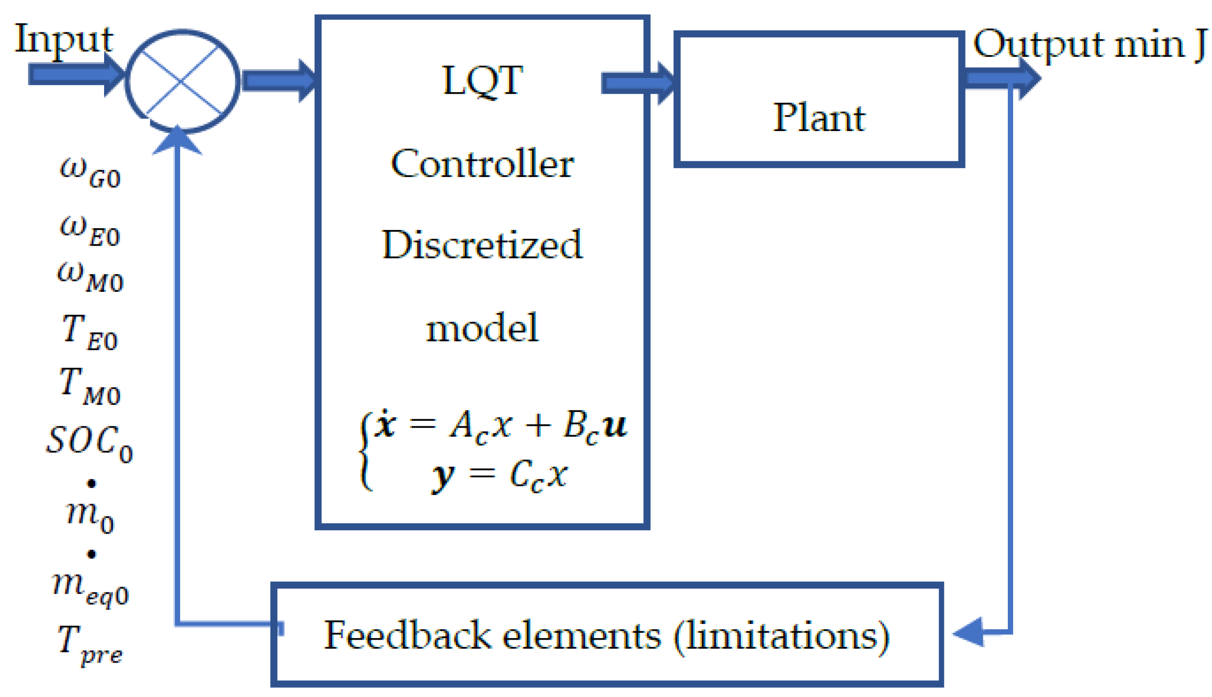
A further way of solving the problem (using the LQT controller) by converting the analytical model represented by the above equations for the discrete model can be found in the literature [30].

4. Results

The tests scenario was conducted according to the architecture in Figure 3.
The key simulation parameters of the test scenario are summarized in Table 2.
Characteristics of operational parameters of working machines for selected driving modes (normal and electric) based on the tests scenario are presented in Figure 4, Figure 5, Figure 6 and Figure 7.
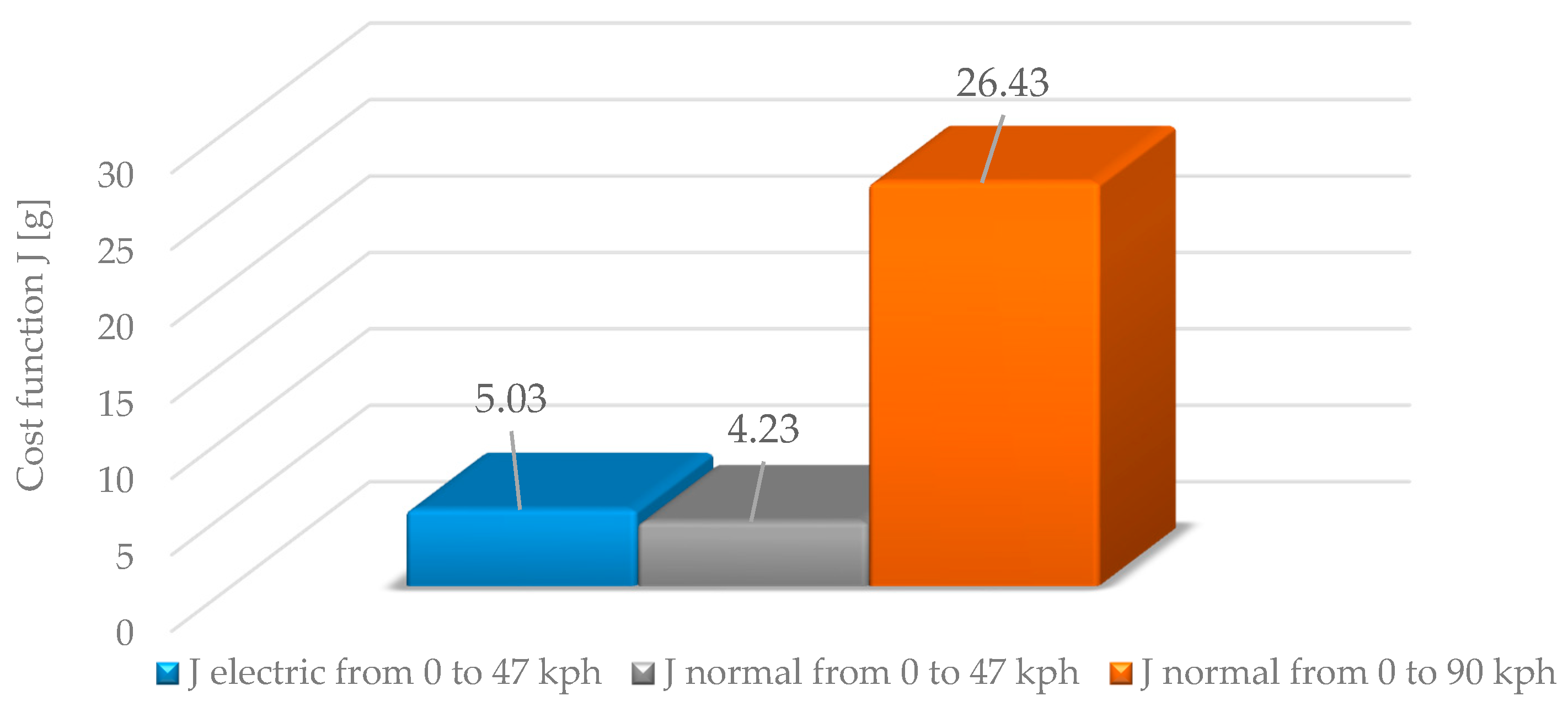
Based on the above characteristics it can be seen that the acceleration of the hybrid electric vehicle in the normal driving mode with the accelerator pedal maximum pressed is spent by a greater decrease in the battery charge level than in the electric driving mode. In the electric mode the vehicle accelerates much slower which is associated with lower energy consumption. While accelerating in the normal driving mode, almost all operational parameters of working machines (torques, powers and rotational speeds) are set within the range of maximum values (corresponding to the given vehicle speed). The situation is different for the electric mode, but this is due to the fact that the driver does not fully press the gas pedal (no maximum power demand). The above considerations also reflect the results of the determined cost function (based on the LQT algorithm) presented below (Figure 8).

5. Discussion

The process of accelerating the hybrid electric vehicle from 0 to 47 km/h in electric mode (partial stroke of the accelerator pedal) lasts for 12 s and transfers into the cost function value (equivalent fuel consumption value) of 5.03 g. Accelerating the hybrid electric vehicle from 0 to 47 km/h in normal mode lasts 4.5 s and transfers into the cost function value of 4.23 g. The acceleration of the hybrid electric vehicle from 0 to 90 km/h in normal mode (the accelerator pedal fully pressed) lasts 11 s and corresponds to the value of the cost function of 26.43 g.
Based on Figure 8, it can be concluded that the hybrid electric vehicle accelerates faster in normal mode than in electric mode. Accelerating from 0 to 47 km/h in normal mode takes 7.5 s less than in electric mode (and corresponds to the lower value of the cost function). This demonstrates the importance of the hybrid electric vehicle acceleration process with fully depressed gas pedal (it is the most energy-efficient). In these conditions the selected driving mode is a little importance.

6. Conclusions

The results calculated on the basis of the relationship from the first part of the article prove its high reliability (the accuracy in the vast majority of results reaches 4%). The operating parameters of the internal combustion engine and electric machines during the hybrid electric vehicle acceleration assume the maximum values in the entire range (corresponding to the given car speeds).
The torque values of the internal combustion engine, corresponding to the external characteristic torque values (full power characteristics), correspond to a high efficiency of the entire powertrain of forty percent (the MPC energy management strategy and the LQT controller automatically “sets” the internal combustion engine into the range of a maximum efficiency). This is transferred into low values of the calculated cost function, which actually means lower fuel consumption.
The tests were preliminary; however, in the longer term, the road measurements of the operating parameters of the internal combustion engine and electric machines can be made, as well as the fuel consumption in steady states (constant values of the vehicle speed and torque loading the wheels of the car) and the measurements of the above parameters according to specific driving cycles (NEDC, WLTP, FTP etc.) using bench tests (chassis dynamometer).

Author Contributions

Conceptualization, K.P.; methodology, W.G.; software, M.L.; validation, K.F.A.; formal analysis, D.G.; investigation, W.G.; resources, K.P.; data curation, M.L.; writing—original draft preparation, W.G.; writing—review and editing, W.G.; visualization, M.L.; supervision, K.F.A. All authors have read and agreed to the published version of the manuscript.

Funding

This research received no external funding.

Conflicts of Interest

The authors declare no conflict of interest.

Nomenclatures

Af[m2]frontal area of vehicle
b [kg/Ws]specific fuel consumption
Cd[-]air drag resistance coefficient
C1[m]number of teeth of the first set satellites
C2[m]number of teeth of the second set of satellites
fd[-] total gear ratio
fr[-]rolling resistance coefficient
fuels[g]fuel consumption
Fp[N]propelling force
F1[N]internal between teeth force of the first gear
F2[N]internal between teeth force of the second gear
g[ms−2]gravitational acceleration
Ibat[A]battery charging/discharging current
J[g]cost function
JE[kgm2]mass moment of inertia of the internal combustion engine
JG[kgm2]mass moment of inertia of the generator MG1
JR[kgm2]mass moment of inertia of the planetary gear ring wheel
JM[kgm2] mass moment of inertia of the electric motor MG2
m[kg]total mass of vehicle
m [kg/s]actual fuel consumption
m e q [kg/s]equivalent fuel consumption (high voltage battery flow)
N[-]number of steps
Pbat[W]power of battery
PE[W]internal combustion engine power
Qmax[Ah]maximum battery capacity
Qused[Ah]battery capacity used
rbat[Ω]internal battery resistance
rd[m]dynamic wheel radius
R[m]number of teeth of the ring gear
R1[m]number of crown wheel teeth
R2[m]number of ring wheel teeth on the electric motor side
s[-]step
SOC[%]state of charge
SOCd[%]desired state of charge
S1[m]number of teeth of the first sun gear
S2[m]number of teeth of the second sun gear
t[s]time
td[-]jump (step level)
Tbrk[Nm]brake torque
Tdes[Nm]desired torque
TEdes[Nm]desired torque of the internal combustion engine
TGdes[Nm]desired torque of the generator
TMdes[Nm]desired torque of the electric motor
Tpre[Nm]expected system torque
Tresis[Nm] resistance torque
TE[Nm]torque of the internal combustion engine
TG[Nm]generator torque
TM[Nm] electric engine torque
TR[Nm] torque of the ring gear of the planetary gear
Ubus[V]voltage in the battery circuit
vveh[ms−1]vehicle speed
VOC[V]open-circuit voltage of the battery
Wu[J/kg]calorific value of fuel
α[°]slope of elevation
αE[-]penalty factor
ωC1[1/s]angular velocity of the satellite yoke C1
ωE[1/s] angular speed of the internal combustion engine,
ωG[1/s]angular speed of the generator
ωM[1/s]angular velocity of the electric motor
ωR[1/s]angular velocity of the crown wheel R (ring)
ωs1[1/s]angular velocity of the sun wheel S1
ωs2[1/s]angular velocity of the sun wheel S2
ρ[-]coefficient occurring between the tracking error and the equivalent fuel consumption
ρA[kgm−3]air density
ηcoulomb[-]Coulomb efficiency
ηE[-]overall engine efficiency
τ E [s]internal combustion engine operation time
τ G [s] generator operation time
τ M [s]electric motor operation time

References

  1. Ripaccioli, G.; Bernardini, D.; Di Cairano, S.; Bemporad, A.; Kolmanovsky, I.V. A stochastic model predictive control approach for series hybrid electric vehicle power management. In Proceedings of the American Control Conference, Baltimore, MD, USA, 30 June–2 July 2010; pp. 5844–5849. [Google Scholar]
  2. Borhan, H.; Vahidi, A.; Wei, L.; Phillips, A.; di Cairano, S.; Kuang, M.; McGee, R. Nonlinear model predictive control of a power-split hybrid electric vehicle: Influence of inclusion of powertrain dynamics. In Proceedings of the Dynamic Systems and Control Conference, Arlington, VA, USA, 31 October–2 November 2011; pp. 1–8. [Google Scholar]
  3. Kleimaier, A.; Schroder, D. An approach for the online optimized control of a hybrid powertrain. In Proceedings of the 7th International Workshop on Advanced Motion Control, Maribor, Slovenia, 3–5 July 2002; pp. 215–220. [Google Scholar]
  4. Guzzella, L.; Sciarretta, A. Vehicle Propulsion Systems, Introduction to Modeling and Optimalization; Springer: Berlin, Germany, 2005; p. 190. [Google Scholar]
  5. Barsali, S.; Miulli, C.; Possenti, A. A control strategy to minimalize fuel consumption of series hybrid electric vehicles. IEEE Trans. Veh. Technol. 2004, 19, 187–195. [Google Scholar]
  6. Delprat, S.; Lauber, J.; Guerra, T.M.; Rimaux, J. Control of a parallel hybrid powertrain: Optimal control. IEEE Trans. Veh. Technol. 2004, 53, 872–881. [Google Scholar] [CrossRef]
  7. Musado, C.; Rizzoni, G.; Staccia, B. A ECMS: An adaptive algorithm for hybrid electric vehicle energy management. In Proceedings of the 44th IEEE Conference Decision Control, European Control Conference, Seville, Spain, 12–15 December 2005; pp. 1816–1823. [Google Scholar]
  8. Zhu, Y.; Chen, Y.; Tian, G.; Wu, H.; Chen, Q. A four-step method to design an energy management strategy for hybrid vehicles. In Proceedings of the American Control Conference, Boston, MA, USA, 30 June–2 July 2004; pp. 156–161. [Google Scholar]
  9. Lin, C.C.; Peng, H.; Grizzle, J.W.; Kang, J.M. Power management strategy for a parallel hybrid electric truck. IEEE Trans. Control Syst. Technol. 2003, 11, 839–849. [Google Scholar]
  10. Lin, C.C.; Peng, H.; Grizzle, J.W. A stochastic control strategy for hybrid electric vehicles. In Proceedings of the American Control Conference, Boston, MA, USA, 30 June–2 July 2004. [Google Scholar]
  11. Back, M. Pradikitive Antriebregulung zum energieoptimalen Betrieb von Hybridfahrzeugen. Ph.D. Dissertation, University Karlsruhe, Karlsruhe, Germany, 2004. [Google Scholar]
  12. Steinmauer, G.; de Re, L. Optimal control of dual power sources. In Proceedings of the 2001 IEEE International Conference on Control Applications, Mexico City, Mexico, 7 September 2001; pp. 422–442. [Google Scholar]
  13. Paganelli, G.; Guezennec, Y.; Rizzoni, G. Optimizing Control Strategy for Hybrid Fuel Cell Vehicle; Tech. Rep.; SAE: Warrendale, PA, USA, 2002. [Google Scholar]
  14. Paganelli, G.; Delprat, S.; Guerra, T.; Rimaux, J.; Santin, J. Equivalent consumption minimization strategy for parallel hybrid powertrains. IEEE Veh. Technol. Conf. 2002, 4, 2076–2081. [Google Scholar]
  15. Sciarretta, A.; Back, M.; Guzzella, L. Optimal control of parallel hybrid electric vehicles. IEEE Trans. Control. Syst. Technol. 2004, 12, 352–363. [Google Scholar] [CrossRef]
  16. Gao, J.; Zhu, G.; Strangas, E.; Sun, F. Equivalent fuel consumption optimal control of a series hybrid electric vehicle. Proc. Inst. Mech. Eng. Part D J. Automob. Eng. 2009, 23, 1003–1018. [Google Scholar] [CrossRef]
  17. Liu, J.; Peng, H. Modeling and control of a power-split hybrid vehicle. IEEE Trans. Control Syst. Technol. 2008, 16. [Google Scholar] [CrossRef]
  18. Liu, J.; Peng, H. Automated modelling of a power-split hybrid vehicles. In Proceedings of the 17th World Congress. The International Federation of Automatic Control, Seoul, Korea, 6–11 July 2008; pp. 4648–4653. [Google Scholar]
  19. Chen, Z.; Xiong, R.; Wang, K.; Jiao, B. Optimal energy management strategy of a plug-in hybrid electric vehicle based on a particle swarm optimization algorithm. Energies 2015, 8, 3661–3678. [Google Scholar] [CrossRef] [Green Version]
  20. Wu, X.; Cao, B.; Wen, J.; Bian, Y. Particle Swarm Optimization for Plug-in Hybrid Electric Vehicle Control Strategy Parameter. In Proceedings of the 2008 IEEE Vehicle Power and Propulsion Conference, Harbin, China, 3–5 September 2008; pp. 1–5. [Google Scholar]
  21. Abido, M.A. Optimal power flow using particle swarm optimization. Int. J. Electr. Power Energy Syst. 2002, 24, 563–571. [Google Scholar] [CrossRef]
  22. Chen, Z.; Xiong, R.; Cao, J. Particle swarm optimization-based optimal power management of plug-in hybrid electric vehicles considering uncertain driving conditions. Energy 2016, 96, 197–208. [Google Scholar] [CrossRef]
  23. Chen, S.-Y.; Hung, Y.-H.; Wu, C.-H.; Huang, S.-T. Optimal energy management of a hybrid electric powertrain system using improved particle swarm optimization. Appl. Energy 2015, 160, 132–145. [Google Scholar]
  24. Hwang, H.-Y.; Chen, J.-S. Optimized fuel economy control of power—Split hybrid electric vehicle with particle swarm optimization. Energies 2020, 13, 2278. [Google Scholar] [CrossRef]
  25. Kim, T.S.; Manzie, C.; Sharma, R. Model predictive control of velocity and torque split in a parallel hybrid vehicle. In Proceedings of the IEEE international conference on systems, San Antonio, TX, USA, 11–14 October 2009; pp. 2014–2019. [Google Scholar]
  26. Borhan, H.A.; Vahidi, A. Model predictive control of a power-split hybrid electric vehicle with combined battery and ultra-capacitor energy storage. In Proceedings of the American control conference, Baltimore, MD, USA, 30 June–2 July 2010; pp. 5031–5036. [Google Scholar]
  27. Moura, S.J.; Fathy, H.K.; Callaway, D.S.; Stein, J.L. A stochastic optimal control approach for power management in plug-in hybrid electric vehicles. IEEE Trans. Veh. Technol. 2011, 19, 545–555. [Google Scholar] [CrossRef] [Green Version]
  28. Yu, K.; Yang, J.; Yamaguchi, D. Model predictive control for hybrid vehicle ecological driving using traffic signal and road slop information. Control Theory Technol. 2015, 13, 17–28. [Google Scholar] [CrossRef]
  29. Yang, J.; Zhu, G. Adaptive recursive prediction of the desired torque of hybrid powertrain. IEEE Trans. Veh. Technol. 2015, 64. [Google Scholar] [CrossRef]
  30. Yang, J.; Zhu, G. Model Predictive Control of a Power Split Hybrid Powertrain. In Proceedings of the American Control Conference (ACC), Boston Marriott Copley Place, MA, USA, 6–8 July 2016. [Google Scholar]
  31. Shi, D.H.; Wang, S.H.; Pierluigi, P.; Chen, L.; Wang, R.; Wang, R. Modeling and optimal energy management of a power split hybrid electric vehicle. Sci. China Tech. Sci. 2017, 60, 713–725. [Google Scholar] [CrossRef]
  32. Cao, J.; Peng, J.; He, H. Modeling and simulation research on power-split hybrid electric vehicle. Energy Procedia 2016, 104, 354–359. [Google Scholar] [CrossRef]
  33. Merkisz, J.; Pielecha, I. Uklady Mechaniczne Pojazdow Hybrydowych; Wydawnictwo Politechniki Poznanskiej: Poznan, Poland, 2015. [Google Scholar]
  34. Ketzer, M.B.; Lima, A.M.N.; Oliveira, A.C.; Jacobina, C.B. Evaluating circuit topologies for battery charge equalization. In Proceedings of the IEEE 39th Annual Conference of the IEEE Industrial Electronics Society, Vienna, Austria, 10–13 November 2013; pp. 743–748. [Google Scholar]
  35. Lin, X.; Stefanopoulou, A.G.; Li, Y.; Anderson, R.D. State of charge imbalance estimation for battery strings under reduced voltage sensing. IEEE Trans. Control Syst. Technol. 2015, 23, 1052–1062. [Google Scholar]
  36. Ouyang, Q.; Chen, J.; Zheng, J.; Fang, H. Optimal cell-to-cell balancing topology design for serially connected lithium-ion battery packs. IEEE Trans. Sustain. Energy 2018, 9, 350–360. [Google Scholar] [CrossRef]
  37. Han, W.; Zou, C.; Zhang, L.; Zhou, C. Estimation of cell SOC evolution and system performance in module-based battery charge equalization systems. IEEE Trans. Smart Grid. 2019, 10, 4717–4727. [Google Scholar] [CrossRef]
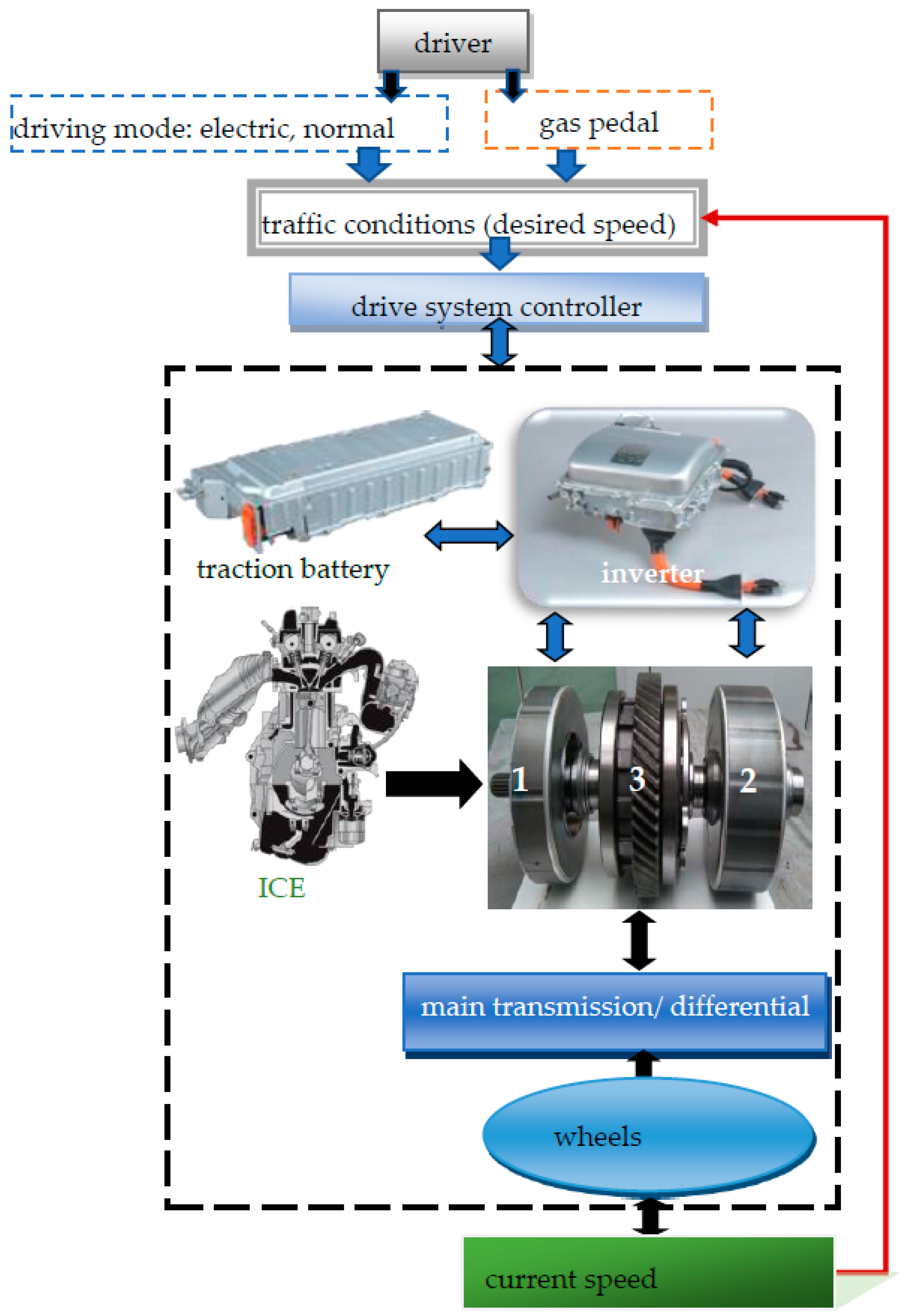
Figure 1. Construction of the power-split hybrid drive model: ICE—internal combustion engine, 1—generator (MG1), 2—electric motor (MG2), 3—planetary gear set.
Energies 13 05818 g001
Figure 2. Torque transmission dynamics model (normal driving mode): 1—combustion engine, 2—MG1 electric machine (starter, generator), 3—planetary gear assembly, 4—MG2 electric machine (electric motor, generator), 5—traction battery, 6—wheels.
Energies 13 05818 g002
Figure 3. Architecture of the linear quadratic tracking (LQT) algorithm.
Energies 13 05818 g003
Figure 4. Level of the traction battery charge and vehicle speed versus time.
Energies 13 05818 g004
Figure 5. Torque of the internal combustion engine, the electric motor and the generator versus time.
Energies 13 05818 g005
Figure 6. Rotational speed of the internal combustion engine, the electric motor and the generator versus time.
Energies 13 05818 g006
Figure 7. Power of the internal combustion engine, the electric motor and generator on time versus time.
Energies 13 05818 g007
Figure 8. Cost function during acceleration of the vehicle in electric and normal modes (from 0 to 47 km/h and from 0 to 90 km/h).
Energies 13 05818 g008
Table 1. (a) Vehicle parameters; (b) Vehicle parameters.
(a)
Total mass1630 kg (1445 kg + 185 kg—driver and passenger)
Dynamic wheel radius0.29 m
Frontal area 1.62 m2
Rolling resistance coefficient 0.0084—tire energy class C
Air drag coefficient0.25
Drive system type HEVpower-split hybrid
Internal Combustion Engine Specification
Ignition typespark ignition
Capacity1.8 dm3
Number of cylinders4
Max. power 73 kW
Max. power rotational speed 5200 rpm
Max. torque 142 Nm
(b)
Max. torque rotational speed 4000 rpm
Mass moment of inertia0.18 kg m2
Generator (MG1) Specification
Typethree-phase synchronous alternating current (AC)
Function generator, internal combustion engine (ICE) starter
Rated voltage 500 V
Maximum output power 42 kW
Max torque45 Nm
Current at max torque75 A
Max. rotational speed 10,000 rpm
Mass moment of inertia0.023 kg m2
Electric Motor (MG2) Specification
Typethree-phase synchronous AC
Function generator, wheel drive
Rated voltage500 V
Maximum output power 60 kW
Maximum torque207 Nm
Current at max torque 230 A
Max. rotational speed13,000 rpm
Mass moment of inertia0.012 kg m2
High Voltage Battery and Inverter Specification
Battery typeNiMH
Nom. voltage 201.6 V
Capacity6.5 Ah
Table 2. Key simulation parameters.
ItemParameterValue
VehicleMass1630 kg
EngineStart delay0.5 s
Time constant1 s
Max torque142 Nm
Power output73 kW
MotorMax torque207 Nm
Power output60 kW
BatterySOC upper bound0.75
SOC lower bound0.45
SOC target0.60
Publisher’s Note: MDPI stays neutral with regard to jurisdictional claims in published maps and institutional affiliations.