Thermal Performance of an Energy Pile Group with a Deeply Penetrating U-Shaped Heat Exchanger


Abstract
:
1. Introduction
- (1)
- The U-shaped configuration is simple in type. However, limited by the length of the pile, its heat transfer path is short, so the overall heat transfer efficiency is not high.
- (2)
- Since the distance between the upward and downward heat exchange tubes of a W-shaped configuration is shorter than that of the U-type, thermal interference will occur and affect the tubes. Although the overall heat exchange efficiency will increase, the heat transfer rate per unit length of tube is not high. The multi-U-shaped configuration is similar.
- (3)
- The multi-U-shaped configuration is complicated and difficult to construct, and there are problems with thermal interference and mutual influence among multiple U-shaped tubes.
- (4)
- Spiral bends are more difficult, and greater thermal interference will also be formed inside the spiral. In addition, although the thermal interference can be reduced by increasing the spacing, the heat transfer efficiency per tube length is still not high.
- (1)
- Compared with the U-shaped and W-shaped configurations, a deeply penetrating U-shaped configuration involves deeper soil, and as the temperature difference between deep soil and water is greater than that between shallow soil and water, the heat exchange is more effective at deeper soil levels for a deeply penetrating 1-U shaped configuration;
- (2)
- Compared with the U-shaped configuration, the deep penetrating U-shaped configuration doubles the length of the heat transfer path and heat transfer time and thus results in a greater amount of heat exchange;
- (3)
- Compared with the W-shaped configuration, the heat transfer length and time are nearly the same as those for the deeply penetrating U-shaped configuration, but the deeply penetrating U-shaped configuration has a greater lateral distance between the descending tube and ascending tube and thus has smaller thermal interference and higher heat transfer performance.
2. Materials and Methods
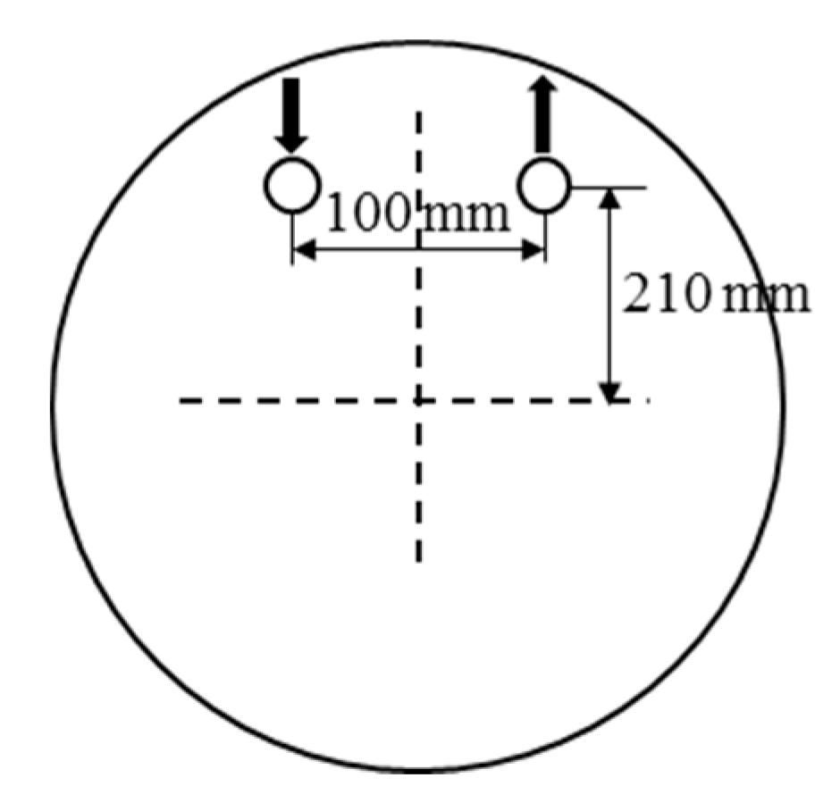
2.1. Characterization of an Energy Pile Group with a Deeply Penetrating U-Shaped Heat Exchanger
2.2. Numerical Model
2.2.1. Solution Algorithms and Simulation Method
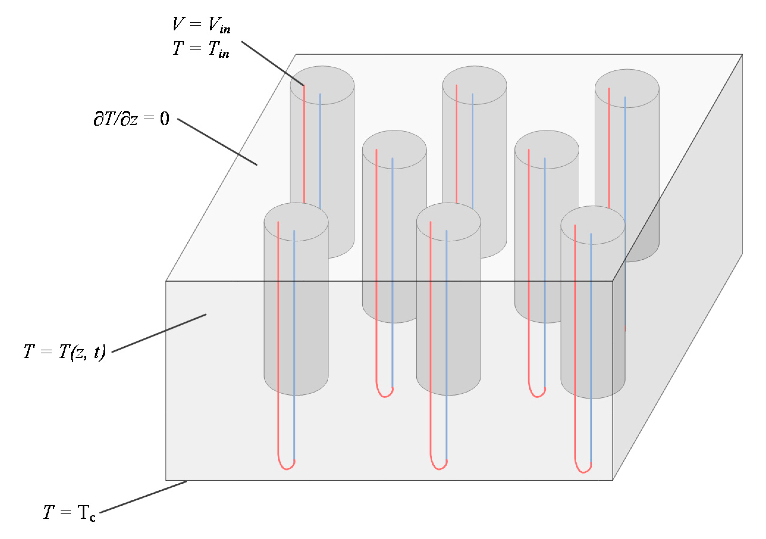
2.2.2. Boundary and Initial Conditions
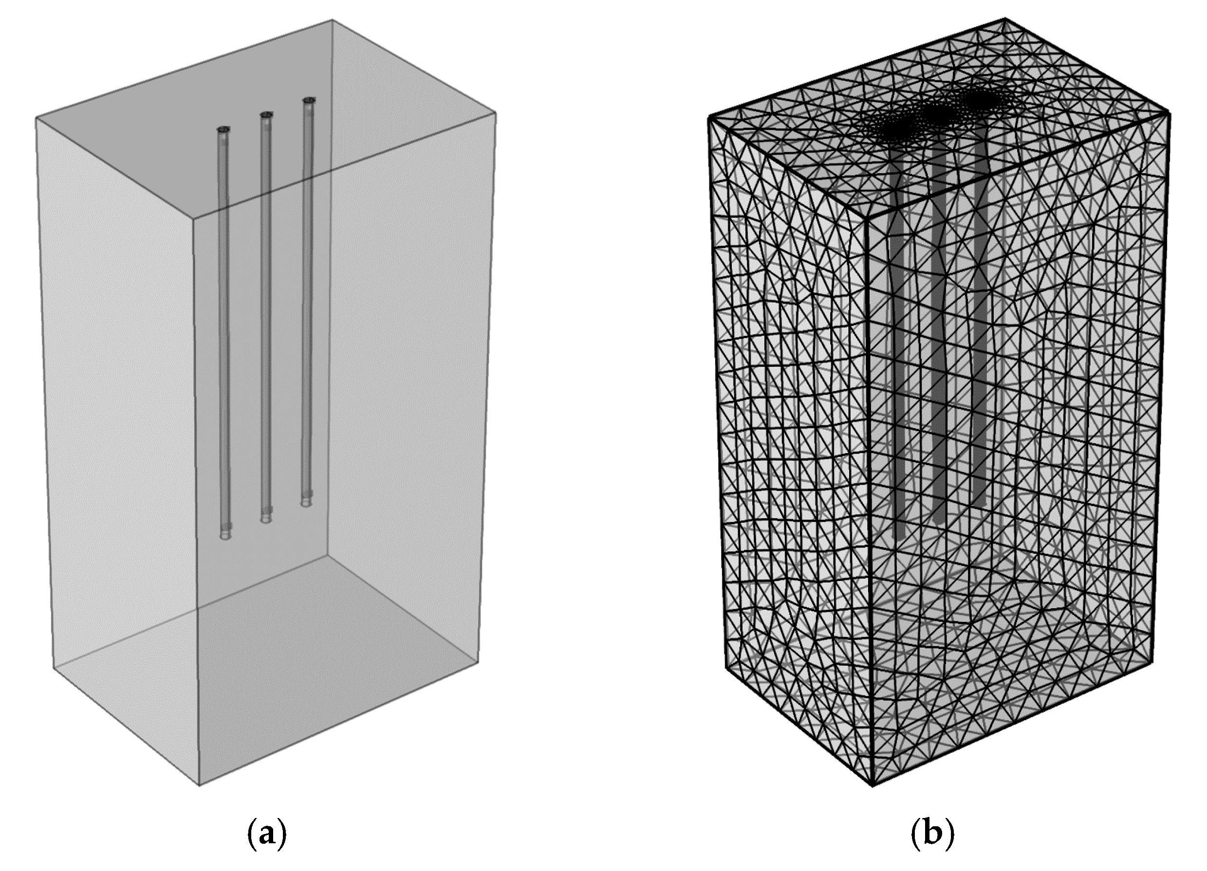
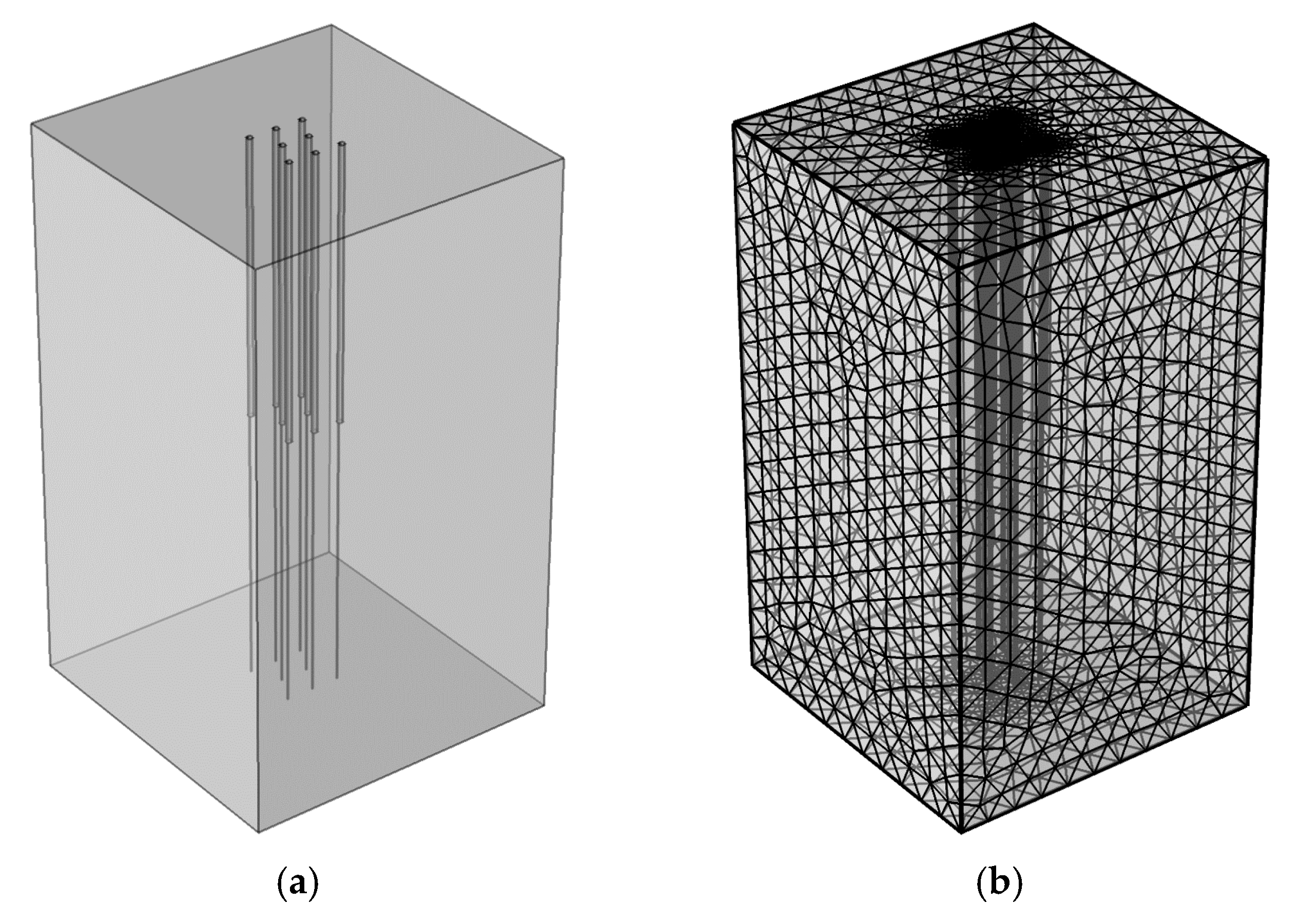
2.2.3. Modeling and Meshing Configuration
2.3. Model Validation
2.3.1. Validation for a Single Pile
2.3.2. Validation for a Pile Group
3. Results and Discussion
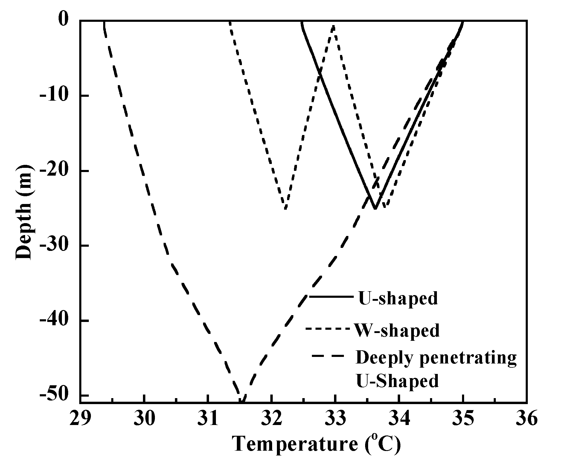
3.1. Comparison of U-Shaped, W-Shaped, and Deeply Penetrating U-Shaped Configurations
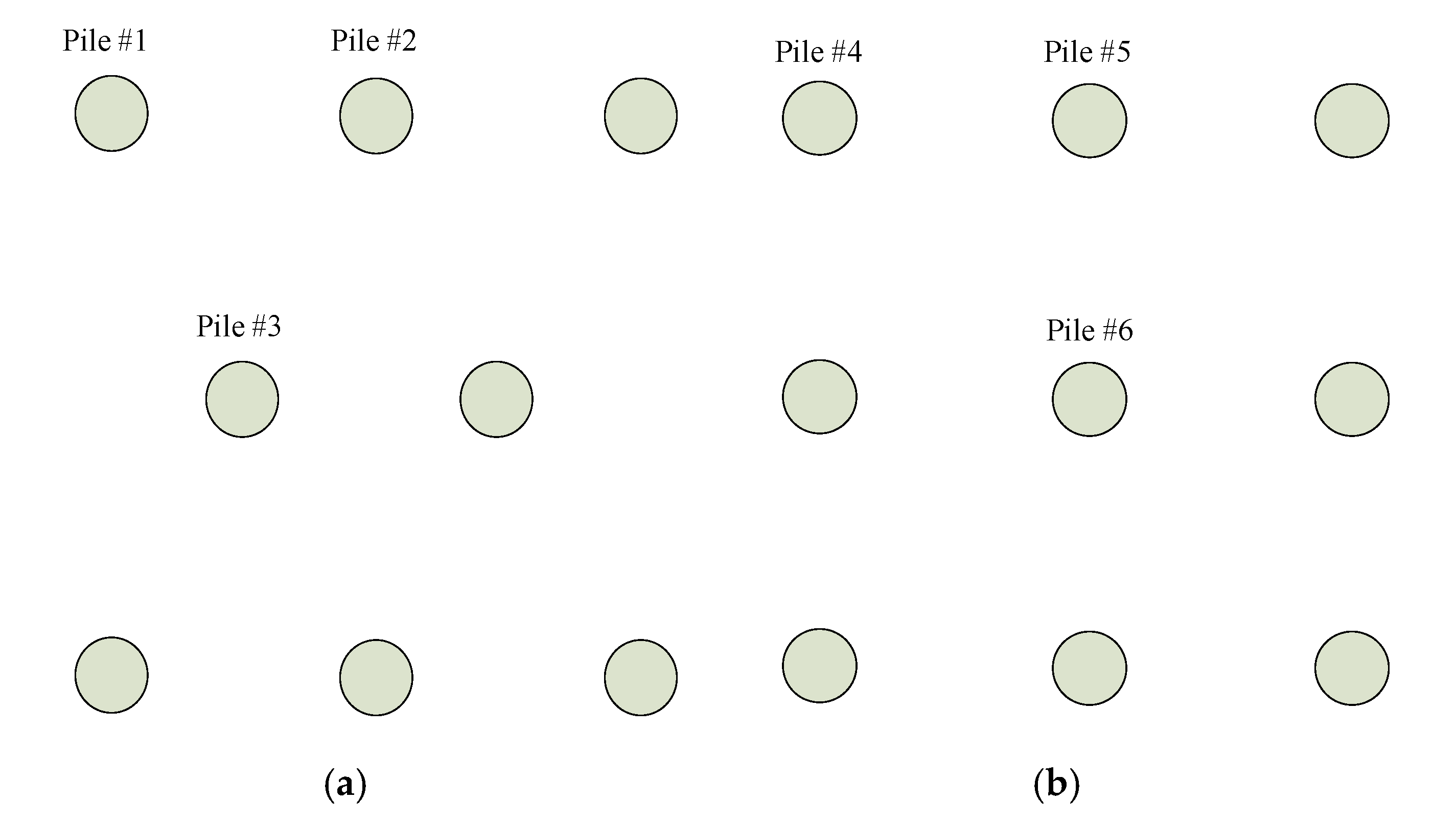
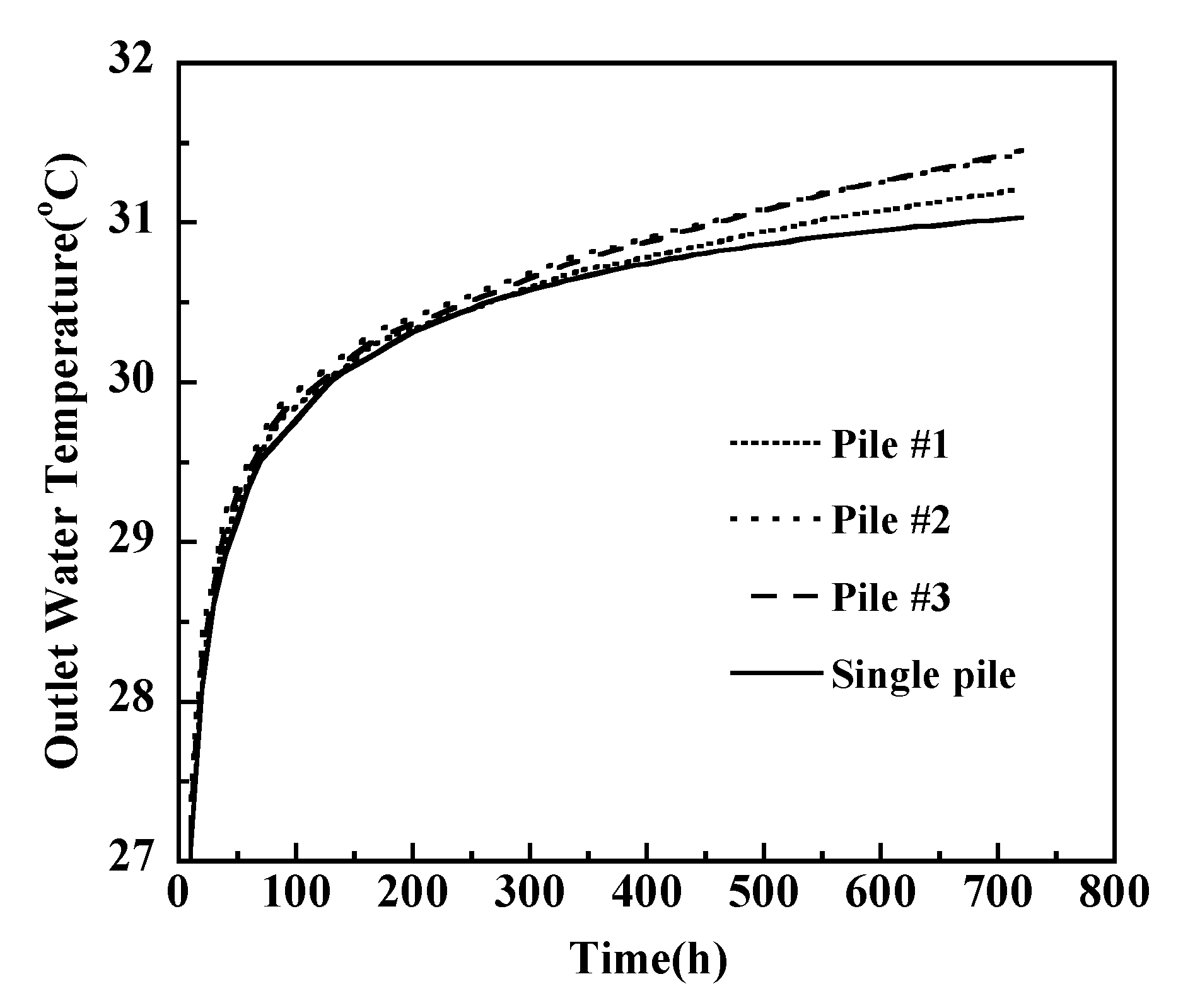
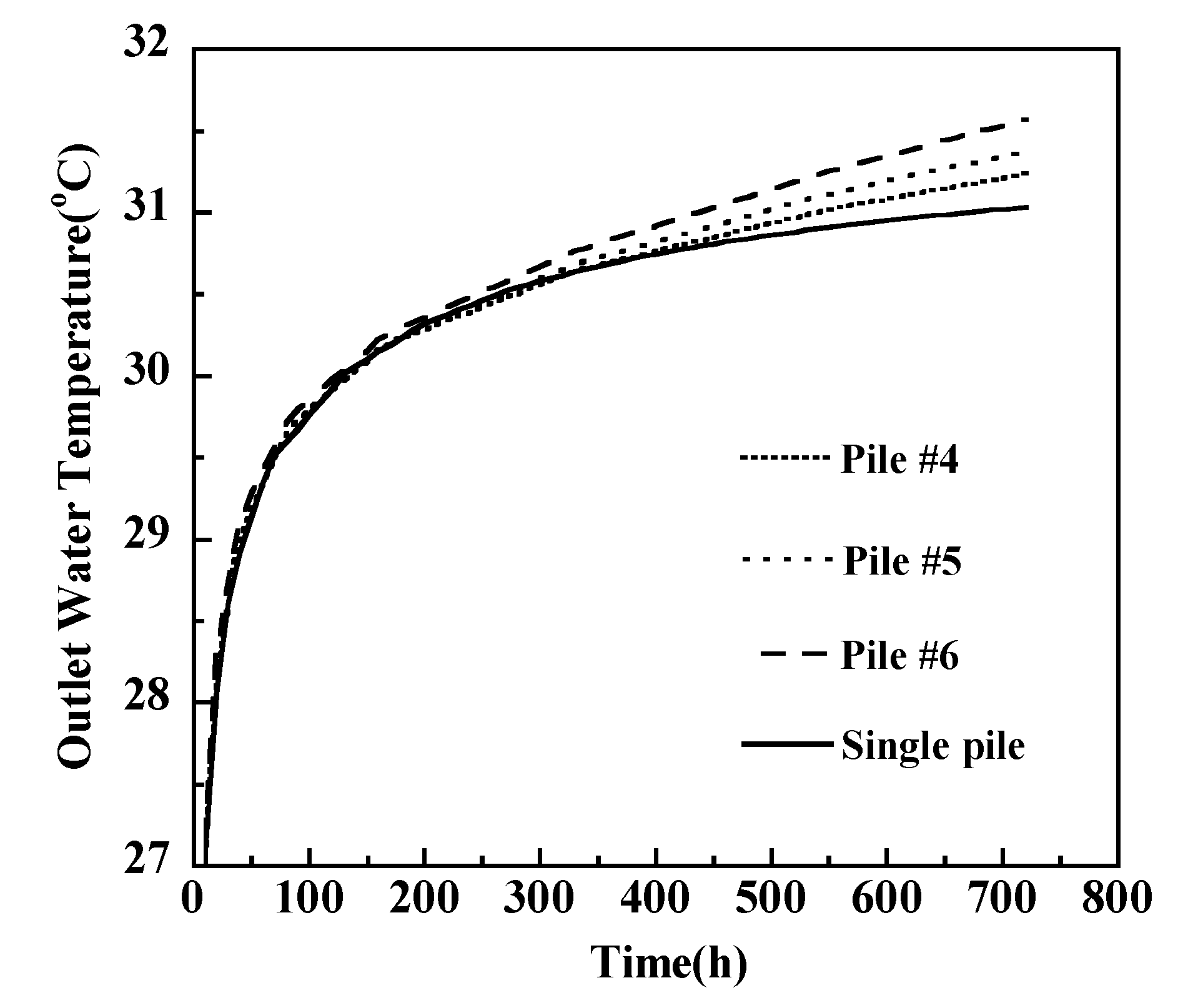
3.2. Comparison of Energy Pile in Pile Group with Quincuncial Arrangement, Squared Arrangement and Single Pile
3.3. Parametric Analysis
3.3.1. Pile Spacing
3.3.2. Pile Diameter
4. Conclusions
- (1)
- Compared with the traditional U-shaped configuration, the proposed deeply penetrating U-shaped configuration indicated superior thermal performance, with a 122% increase in the total heat transfer rate, Q, and a 9% increase in the heat transfer rate per unit length of the tube, Q*. Compared with the traditional W-shaped configuration, the proposed configuration indicated a 54% increase in Q and a 50% increase in Q*.
- (2)
- For the pile group, 300 h is not long enough to cause thermal interference. After 300 h, thermal interference becomes evident, which causes a decrease in the heat transfer capacity. The corner pile indicates a nonnegligible heat transfer rate 6.8% and 9.9% higher than the central pile in quincuncial and squared arrangements, respectively, according to the example in this study.
- (3)
- An increase in the pile spacing leads to an increase in the heat transfer rate. Purely from the standpoint of thermal performance, the pile spacing is recommended to be more than 6.8 times the pile diameter to reduce the influence of the pile group on the heat transfer capacity.
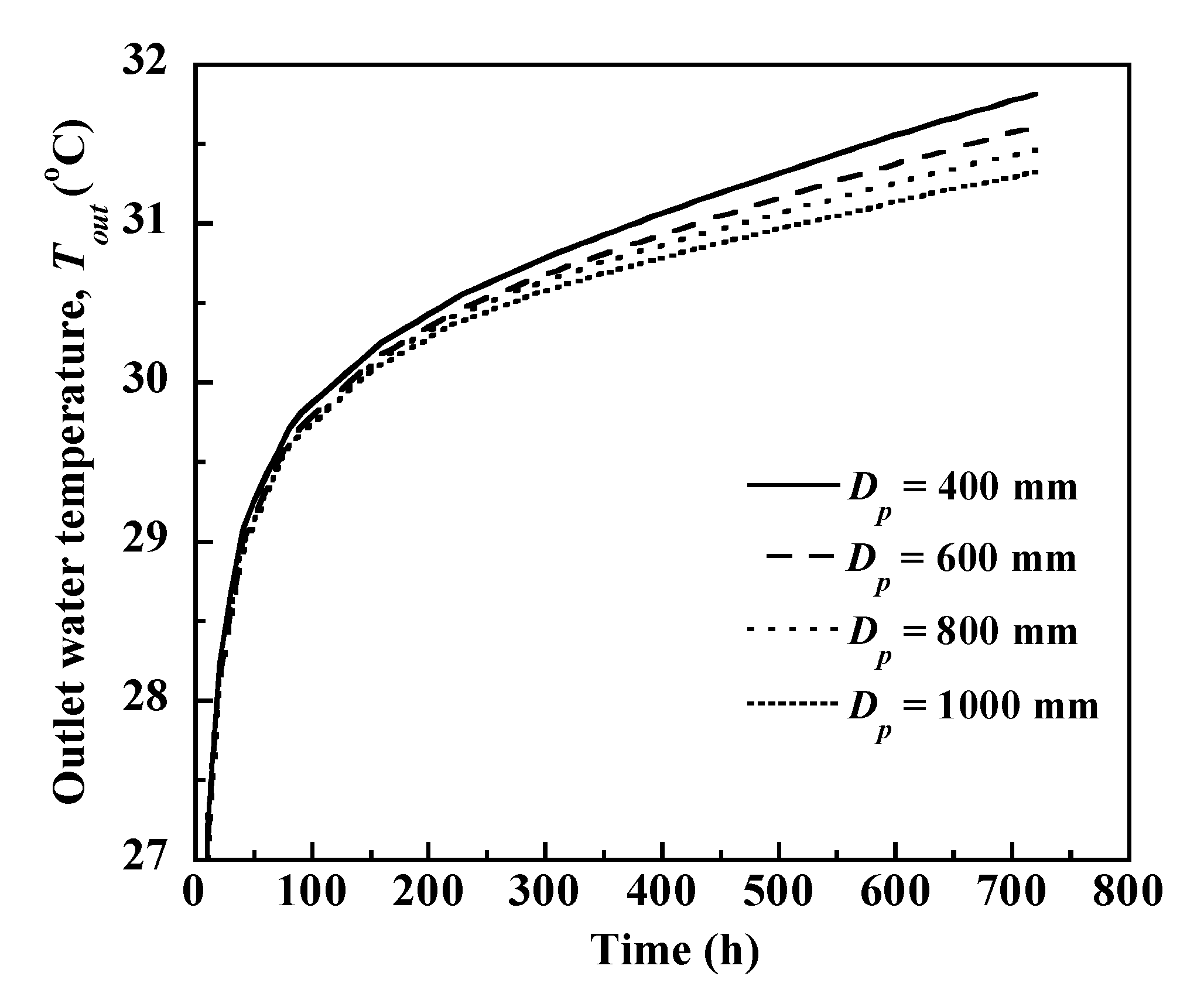
- (4)
- The heat transfer rate increases as the pile diameter increases. An increase of approximately 15.4% can be observed if the pile diameter increases from 400 mm to 1000 mm.
Author Contributions
Funding
Conflicts of Interest
References
- Tarnawski, V.R.; Leong, W.H.; Momose, T.; Hamada, Y. Analysis of ground source heat pumps with horizontal ground heat exchangers for northern Japan. Renew. Energy 2009, 34, 127–134. [Google Scholar] [CrossRef]
- Self, S.J.; Reddy, B.V.; Rosen, M.A. Geothermal heat pump systems: Status review and comparison with other heating options. Appl. Energy 2013, 101, 341–348. [Google Scholar] [CrossRef]
- Hamada, Y.; Saitoh, H.; Nakamura, M.; Kubota, H.; Ochifuji, K. Field performance of an energy pile system for space heating. Energy Build. 2007, 39, 517–524. [Google Scholar] [CrossRef]
- Benli, H.; Durmuş, A. Evaluation of ground-source heat pump combined latent heat storage system performance in greenhouse heating. Energy Build. 2009, 41, 220–228. [Google Scholar] [CrossRef]
- Ozturk, M. Energy and exergy analysis of a combined ground source heat pump system. Appl. Therm. Eng. 2014, 73, 362–370. [Google Scholar] [CrossRef]
- Li, Z. A new constant heat flux model for vertical U-tube ground heat exchangers. Energy Build. 2012, 45, 311–316. [Google Scholar] [CrossRef]
- Gu, Y.; O’Neal, D.L. Development of an equivalent diameter expression for vertical U-Tubes used in ground-coupled heat pumps. ASHRAE Trans. 1998, 104, 347–355. [Google Scholar]
- Beier, R.A. Transient heat transfer in a U-tube borehole heat exchanger. Appl. Therm. Eng. 2014, 62, 256–266. [Google Scholar] [CrossRef]
- Yang, W.; Shi, M.; Liu, G.; Chen, Z. A two-region simulation model of vertical U-tube ground heat exchanger and its experimental verification. Appl. Energy 2009, 86, 2005–2012. [Google Scholar] [CrossRef]
- Adam, D.; Markiewicz, R. Energy from earth-coupled structures, foundations, tunnels and sewers. Geotechnique 2009, 59, 229–236. [Google Scholar] [CrossRef]
- Brandl, H. Energy foundations and other thermo-active ground structures. Geotechnique 2006, 56, 81–122. [Google Scholar] [CrossRef]
- Morino, K.; Oka, T. Study on heat exchanged in soil by circulating water in a steel pile. Energy Build. 1994, 21, 65–78. [Google Scholar] [CrossRef]
- Park, H.; Lee, S.R.; Yoon, S.; Choi, J.C. Evaluation of thermal response and performance of PHC energy pile: Field experiments and numerical simulation. Appl. Energy 2013, 103, 12–24. [Google Scholar] [CrossRef]
- Abdelaziz, S.L.; Olgun, C.G.; Martin, J.R., II. Design and operational considerations of geothermal energy piles. In Proceedings of the Geo-Front. 2011 Adv. Geotech. Eng., Dallas, TX, USA, 13–16 March 2011; pp. 450–459. [Google Scholar]
- Abdelaziz, S.L.; Ozudogru, T.Y. Selection of the design temperature change for energy piles. Appl. Therm. Eng. 2016, 107, 1036–1045. [Google Scholar] [CrossRef]
- Caulk, R.; Ghazanfari, E.; McCartney, J.S. Parameterization of a calibrated geothermal energy pile model. Geomech. Energy Environ. 2016, 5, 1–15. [Google Scholar] [CrossRef] [Green Version]
- You, S.; Cheng, X.; Yu, C.; Dang, Z. Effects of groundwater flow on the heat transfer performance of energy piles: Experimental and numerical analysis. Energy Build. 2017, 155, 249–259. [Google Scholar] [CrossRef]
- Batini, N.; Rotta Loria, A.F.; Conti, P.; Testi, D.; Grassi, W.; Laloui, L. Energy and geotechnical behaviour of energy piles for different design solutions. Appl. Therm. Eng. 2015, 86, 199–213. [Google Scholar] [CrossRef] [Green Version]
- Jalaluddin; Miyara, A.; Tsubaki, K.; Inoue, S.; Yoshida, K. Experimental study of several types of ground heat exchanger using a steel pile foundation. Renew. Energy 2011, 36, 764–771. [Google Scholar] [CrossRef]
- Bezyan, B.; Porkhial, S.; Mehrizi, A.A. 3-D simulation of heat transfer rate in geothermal pile-foundation heat exchangers with spiral pipe configuration. Appl. Therm. Eng. 2015, 87, 655–668. [Google Scholar] [CrossRef]
- Zhao, Q.; Liu, F.; Liu, C.; Tian, M.; Chen, B. Influence of spiral pitch on the thermal behaviors of energy piles with spiral-tube heat exchanger. Appl. Therm. Eng. 2017, 125, 1280–1290. [Google Scholar] [CrossRef]
- Carotenuto, A.; Marotta, P.; Massarotti, N.; Mauro, A.; Normino, G. Energy piles for ground source heat pump applications: Comparison of heat transfer performance for different design and operating parameters. Appl. Therm. Eng. 2017, 124, 1492–1504. [Google Scholar] [CrossRef]
- Park, S.; Sung, C.; Jung, K.; Sohn, B.; Chauchois, A.; Choi, H. Constructability and heat exchange efficiency of large diameter cast-in-place energy piles with various configurations of heat exchange pipe. Appl. Therm. Eng. 2015, 90, 1061–1071. [Google Scholar] [CrossRef]
- Huang, G.; Yang, X.; Liu, Y.; Zhuang, C.; Zhang, H.; Lu, J. A novel truncated cone helix energy pile: Modelling and investigations of thermal performance. Energy Build. 2018, 158, 1241–1256. [Google Scholar] [CrossRef]
- Bouhacina, B.; Saim, R.; Oztop, H.F. Numerical investigation of a novel tube design for the geothermal borehole heat exchanger. Appl. Therm. Eng. 2015, 79, 153–162. [Google Scholar] [CrossRef]
- Jahanbin, A. Thermal performance of the vertical ground heat exchanger with a novel elliptical single U-tube. Geothermics 2020, 86, 101804. [Google Scholar] [CrossRef]
- Pu, H.; Lyu, W.; Xiao, H.; Hu, D.; Ruan, Q. A kind of high-efficiency heat-exchanger energy pile. China Patent No. 201820283459.0, 2 October 2018. (In Chinese). [Google Scholar]
- Xiao, H.; Gao, H.Z.C.; Xiao, Y.; Ma, Q.; Que, M.; Dong, Y.; Liu, Y.; Li, L. Construction method for deep-buried heat exchange system of cast-in-place energy pile. China Patent No. 201810100503.4, 15 November 2019. (In Chinese). [Google Scholar]
- You, S.; Cheng, X.; Guo, H.; Yao, Z. In-situ experimental study of heat exchange capacity of CFG pile geothermal exchangers. Energy Build. 2014, 79, 23–31. [Google Scholar] [CrossRef]
- Carslaw, H.S.; Jaeger, J.C. Conduction of Heat in Solids, 2nd ed.; Clarendon Press: Oxford, UK, 2008. [Google Scholar]
- Taler, D. Numerical Modelling and Experimental Testing of Heat Exchangers; Springer: Cham, Switzerland, 2019; pp. 38–46. [Google Scholar]
- Gao, J.; Zhang, X.; Liu, J.; Li, K.S.; Yang, J. Thermal performance and ground temperature of vertical pile-foundation heat exchangers: A case study. Appl. Therm. Eng. 2008, 28, 2295–2304. [Google Scholar] [CrossRef]
- Suryatriyastuti, M.E.; Mroueh, H.; Burlon, S. Understanding the temperature-induced mechanical behaviour of energy pile foundations. Renew. Sustain. Energy Rev. 2012, 16, 3344–3354. [Google Scholar] [CrossRef]


| Material | Thermal Conductivity, ks (W/m·K) | Specific Heat Capacity, cs (J/kg·K) | Density, ρs (kg/m3) |
|---|---|---|---|
| Soil | 1.3 | 1200 | 1847 |
| Concrete | 1.628 | 837 | 2500 |
| Tube | 0.42 | 1465 | 1100 |
| Water | 0.6 | 4182 | 998.2 |
| Parameter | Value |
|---|---|
| Soil Domain (m) | 5 × 5 × 35 |
| Pile Length (m) | 25.5 |
| Pile Diameter (m) | 0.6 |
| Tube Configuration | U-shaped |
| Tube Diameter (mm) | 20 |
| Tube Thickness (mm) | 4 |
| Tube Depth (m) | 25 |
| Water Flow Rate (m3/h) | 0.342 |
| Inlet Water Temperature (°C) | 35 |
| Annual Average Temperature (°C) | 18.2 |
| Operating Mode | summer |
| Testing Time (h) | 3 |
| Inlet Water Temperature, Tin (°C) | Outlet Water Temperature, Tout (°C) | Temperature Variation, ΔT (°C) | Heat Transfer Rate, Q (W) | |
|---|---|---|---|---|
| This study | 35 | 31.64 | 3.37 | 2365 |
| Gao et al. [32] | 35.13 | 31.56 | 3.57 | 2505 |
| Parameter | Value |
|---|---|
| Pile Length (m) | 18 |
| Pile Diameter (m) | 0.42 |
| Pile Spacing (m) | 2 |
| Tube Configuration | W-shaped |
| Tube Depth (m) | 17.5 |
| Tube Diameter (mm) | 25 |
| Tube Thickness (mm) | 4 |
| Water Flow Velocity (m/s) | 0.51 |
| Ambient Temperature (°C) | 16 |
| Operating Mode | summer |
| Inlet Water Temperature (°C) | 35 |
| Inlet water Temperature, Tin (°C) | Outlet Water Temperature, Tout (°C) | Temperature Variation, ΔT (°C) | Heat Transfer Rate, Q (W) | |
|---|---|---|---|---|
| This study | 35 | 32.85 | 2.15 | 2260 |
| You et al. [29] | 33.04 | 1.96 | 2070 |
| Tube Configuration | Outlet Water Temperature, Tout (°C) | Heat Transfer Rate, Q (W) | Heat Transfer Rate per Unit Length of Tube, Q* (W/m) |
|---|---|---|---|
| U-Shaped | 32.47 | 995 | 19.85 |
| W-Shaped | 31.35 | 1436 | 14.44 |
| Deeply Penetrating U-Shaped | 29.38 | 2211 | 21.64 |
| Pile Arrangement | Pile Number | Inlet Water Temperature, Tin (°C) | Outlet Water Temperature, Tout (°C) | Temperature Variation, ΔT (°C) | Heat Transfer Rate, Q (W) |
|---|---|---|---|---|---|
| Quincuncial | 1 | 35 | 31.21 | 3.79 | 2659 |
| 2 | 31.43 | 3.57 | 2505 | ||
| 3 | 31.45 | 3.55 | 2491 | ||
| Squared | 4 | 31.23 | 3.77 | 2646 | |
| 5 | 31.37 | 3.63 | 2547 | ||
| 6 | 31.57 | 3.43 | 2407 | ||
| Single pile | − | 31.03 | 3.97 | 2786 |
| Pile Spacing, S (m) | Pile Diameter, Dp (mm) |
|---|---|
| 2.1 | 400 |
| 2.6 | 600 |
| 3.1 | 800 |
| 3.6 | 1000 |
| 4.1 | − |
| 4.6 | − |
| Pile Spacing, S (m) | Pile Number | Inlet Water Temperature, Tin (°C) | Outlet Water Temperature, Tout (°C) | Temperature Variation, ΔT (°C) | Heat Transfer Rate, Q (W) |
|---|---|---|---|---|---|
| 2.1 | 1 | 35 | 31.51 | 3.49 | 2449 |
| 2 | 31.75 | 3.25 | 2281 | ||
| 3 | 32.05 | 2.95 | 2070 | ||
| 2.6 | 1 | 35 | 31.23 | 3.77 | 2646 |
| 2 | 31.32 | 3.63 | 2547 | ||
| 3 | 31.57 | 3.43 | 2407 | ||
| 3.1 | 1 | 35 | 31.13 | 3.87 | 2716 |
| 2 | 31.20 | 3.80 | 2667 | ||
| 3 | 31.27 | 3.73 | 2617 | ||
| 3.6 | 1 | 35 | 31.06 | 3.94 | 2765 |
| 2 | 31.10 | 3.90 | 2737 | ||
| 3 | 31.13 | 3.87 | 2716 | ||
| 4.1 | 1 | 35 | 31.00 | 4.00 | 2807 |
| 2 | 31.02 | 3.98 | 2793 | ||
| 3 | 30.96 | 4.04 | 2835 | ||
| 4.6 | 1 | 35 | 31.03 | 3.97 | 2786 |
| 2 | 31.02 | 3.98 | 2793 | ||
| 3 | 31.01 | 3.99 | 2800 | ||
| 5.1 | 1 | 35 | 31.07 | 3.93 | 2758 |
| 2 | 31.05 | 3.95 | 2772 | ||
| 3 | 31.04 | 3.96 | 2779 |
| Pile Diameter, Dp (mm) | Inlet Water Temperature, Tin (°C) | Outlet Water temperature, Tout (°C) | Temperature Variation, ΔT (°C) | Heat Transfer Rate, Q (W) |
|---|---|---|---|---|
| 400 | 35 | 31.81 | 3.19 | 2238 |
| 600 800 1000 | 31.61 31.46 31.32 | 3.39 3.54 3.68 | 2379 2484 2582 |
Publisher’s Note: MDPI stays neutral with regard to jurisdictional claims in published maps and institutional affiliations. |
© 2020 by the authors. Licensee MDPI, Basel, Switzerland. This article is an open access article distributed under the terms and conditions of the Creative Commons Attribution (CC BY) license (http://creativecommons.org/licenses/by/4.0/).
Share and Cite
Lyu, W.; Pu, H.; Chen, J. Thermal Performance of an Energy Pile Group with a Deeply Penetrating U-Shaped Heat Exchanger. Energies 2020, 13, 5822. https://doi.org/10.3390/en13215822
Lyu W, Pu H, Chen J. Thermal Performance of an Energy Pile Group with a Deeply Penetrating U-Shaped Heat Exchanger. Energies. 2020; 13(21):5822. https://doi.org/10.3390/en13215822
Chicago/Turabian StyleLyu, Weidong, Hefu Pu, and Jiannan (Nick) Chen. 2020. "Thermal Performance of an Energy Pile Group with a Deeply Penetrating U-Shaped Heat Exchanger" Energies 13, no. 21: 5822. https://doi.org/10.3390/en13215822