1. Introduction
High-speed motors are widely implemented for fan, pump, and compressor applications where the operating speed is beyond 20~30 krpm. Compared to universal motors, high-speed PM motors use voltage source inverters instead of mechanical brushes for the AC voltage commutation [
1,
2]. Due to the progress on the pulse width modulation (PWM) control and high-density magnets, PM-type high-speed motors can further increase their power density by increasing the operating speed. Consequently, these high-density motors are compatible with moving applications under the size constraint [
3].
Because of the high-speed rotation, the rotor radial force causes vibration, leading to additional mechanical losses and degradation of the bearing reliability. As reported in [
4], the radial force is induced by the interaction between the rotor magnet flux and stator armature flux. An analytical model of radial force is derived in [
5]. The radial force frequency is proportional to the rotor operating speed. Once the force frequency is close to the rotor mechanical natural frequency, the visible resonant vibration appears at high speed. Considering PM motors with surface-mounted magnets, the resonant vibration can also split magnets from the rotor surface. To improve the PM rotor structure, [
6] proposed a rotor with a whole cylindrical magnet without an iron shaft to maintain the mechanical structure at high speed. In addition, [
7] designed a rotor pole with several zigzag skew magnets to reduce the radial force. The cogging torque was reduced as well.
PM synchronous motors require armature windings to generate the electromagnetic torque. In general, three-phase armature windings can be fixed through stator teeth/slots design or direct attachment on the stator core. The slotless stator without iron teeth results in advantages at high speed [
8,
9]. In [
10] with slotless stators, secondary armature flux harmonics are reduced due to the lack of a slotted effect during the rotation. In this case, rotor eddy current losses at high speed can be suppressed. However, the slotless stator requires a higher current density to maintain the same torque output. It causes the thermal issue on stator windings. In [
11] three different slotless windings are compared among armature flux harmonics, current density, and rotor eddy current loss. The slotless windings with a diamond shape cause additional armature flux harmonics, which is not suited for high-speed operation. In [
12] different steel thicknesses are compared for the slotless stator. At high speed, the thinner steel is recommended to reduce the axial eddy current losses reflected by the skin effect. However, slotless windings result in higher copper losses due to the lower armature flux density. Recently, [
13] proposed slotless windings through a printed circuit board. The low winding resistance is the primary advantage. Based on these studies, the slotless windings might be suitable for high-speed motors; however, the high current density and low torque density are two concerns.
Considering the PM rotor structure at high speed, an additional rotor sleeve is required to fix magnets on the rotor surface. However as mentioned in [
14] the rotor sleeve also degrades the energy conversion performance at high speed. In general, the rotor sleeve can be formulated by copper, steel, or carbon-fiber. For the copper sleeve, additional eddy current loss is induced once the armature flux flows across the sleeve. Besides, for the steel sleeve, leakage flux instead of eddy current is the result since the steel is an additional magnetic material on the rotor [
14]. In [
15] the rotor sleeve is realized by carbon-fiber. In this material, no eddy current and leakage flux is induced. However, carbon-fiber shows poor thermal conduction. This sleeve-covered rotor requires additional temperature consideration to dissipate the heat outside of the rotor. It is observed that the sleeve design is the tradeoff between the rotor strength and motor efficiency.
Six-step trapezoidal brushless DC drives are widely implemented for high-speed motors due to the simple controller implementation with negligible delay issues [
16,
17,
18]. However, because only the two-phase conduction is applied, considerable third-order and fifth-order current harmonics are induced. In this case, relatively high eddy current loss occurs on the rotor, leading to the rotor thermal issue at high speed [
19]. On the other hand, sinusoidal-based vector control uses space vector pulse width modulation (PWM) to manipulate the sinusoidal current. Without secondary current harmonics, the eddy current loss in the rotor can be minimized. However, as reported in [
20], the complicated signal process, including the voltage delay compensation and inductance cross-coupling decoupling, is the major challenge. For trapezoidal six-step commutation, a PM motor with the minor influence of non-sinusoidal current harmonics is desired to minimize the motor rotor loss.
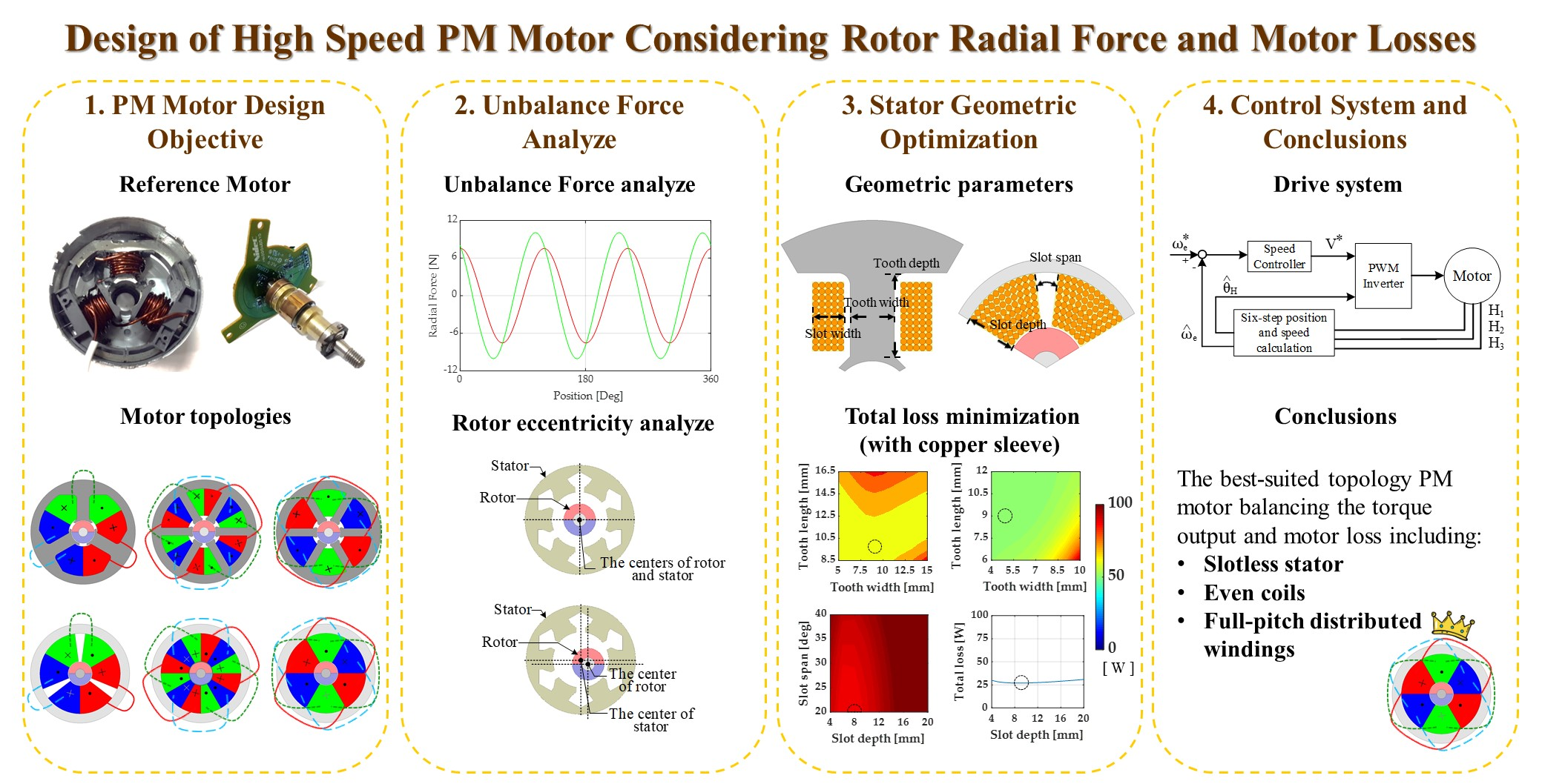
This paper designed a suitable high-speed PM motor for the fan system. The desired power is 400 W at the speed 80 krpm. Different from the design of conventional motors, high-speed PM motors are primarily limited by rotor unbalanced radial forces, rotor losses, and rotor mechanical strength. These three design issues are improved through several design considerations. First, the rotor radial force is minimized based on the selection of tooth numbers and windings. Second, rotor losses are minimized through the motor geometric design using a two-dimensional sensitivity analysis. In order to maintain the rotor structure at high speed, the cooper sleeve is typically added on magnets. However, the rotor sleeve-reflected loss dependent on rotor frequency is significant at high speed. This sleeve loss can be minimized with slotless windings. In this paper, six PM motors with different tooth numbers, stator core, and winding layouts are compared among rotor radial forces, rotor losses, and sleeve effects. All the motor design methods are verified based on nonlinear FEA.
3. Rotor Unbalanced Force Analysis
This section analyzes the rotor unbalanced force for these six motors based on FEA. To investigate the performance of the motor, including the nonlinear properties and the effect of the complex geometry, the electromagnetic FEA is a popular method. On this basis, FEA is a numerical method to solve the physical system modeled by complicated differential equations. For AC motors, Maxwell’s equations are the main target equations to be solved. FEA solves the magnetic vector potential within a well-defined 2-D or 3-D region. The magnetic flux density and magnetic energy can then be derived. To analyze the mechanical properties of the motion system, e.g., electromagnetic torque, the virtual-work method is applied.
Figure 2a illustrates the original stator with only 3 coils. The corresponding characteristics are listed by 3Slot-1CS in
Table 2. However, the design of 3Slot-1CS results in several disadvantages. First, the asymmetric stator tooth arrangement and windings layout causes an unbalanced radial force. Besides, 3Slot-1CS contains a poor winding factor with only 0.866 as calculated by (1). These issues are investigated as follows.
3.1. Rotor Magnetic Force
The unbalanced magnetic force is one key issue in high-speed motors. In general, the magnetic force results in rotor eccentricity, acoustic noise, vibration, and mechanical loss. These side effects all increase as the speed increases, limiting the high-speed region. The magnetic force consists of radial force
Frad and tangential force
Ftan. As reported from [
23,
24], the Maxwell stress tensor equation can be used to calculate the magnetic force in the rotor. It is shown to be:
where
Ls is the stack length,
μ0 is the magnetic permeability of air,
lc is the integration contour,
Bn is the radial magnetic flux density, and
Bt is the tangential flux density. It is important to note that
Ftan contributes to the electromagnetic torque while
Frad results in the unbalanced rotor vibration and hence acoustic noises.
Based on FEA,
Figure 3 illustrates the magnetic radial force
Frad versus the rotor position. Regarding the rotor eccentricity simulation,
Figure 4a illustrates the ideal FEA motor simulation without rotor eccentricity. In this case, both the stator and rotor have the same center location. At no load without the armature flux,
Frad contains the spatial information with respect to 3
θe. The peak values occur when the rotor positions are respectively at 0, 120, and 240 deg. It is observed that the peak radial force occurs when the rotor magnet is aligned with the stator tooth. By contrast at full load, the location of the peak value slightly moves away from three positions with the increased magnitude.
Table 3 summarizes the peak radial force among the six analyzed PM motors in
Figure 2. On this basis, the radial magnetic force is a result of the interaction between rotor magnets and stator teeth. Considering the slotted stator, 3Slot-1CS contains the worst radial magnetic force because of the asymmetric stator tooth with the odd coils of 3. By designing the symmetric stator with even coils, this radial force disappears due to the force cancellation between two teeth with same-phase windings. By contrast, for the slotless stator, the radial force should be zero because of the lack of an iron tooth for the interaction with the magnets. However, a small amount of radial force still appears, resulting from the influence of armature flux as load increases, e.g., 3Sless-1CS. Similar to slotted stators, this force is cancelled with symmetric stator coils.
It is noted that the radial force analysis in
Table 3 is calculated under the assumption of ideal rotor fabrication. For actual motors, the assembly tolerance due to the rotor installation should be considered.
Figure 4b demonstrates the rotor eccentricity. In this case, the rotor center deviates from the original stator center. Under this effect,
Table 4 investigates the peak radial force with manufacturing error. In this simulation, 10% rotor eccentricity is analyzed considering the motor fabrication tolerance. With additional rotor eccentricity, the radial force increases even for motors with symmetric stator. However, compared to motors with an asymmetric stator, the peak radial force magnitude is still sufficiently lower than the magnitude with a symmetric stator. Based on this simulation, it is concluded that the unbalanced radial force can be cancelled using the symmetric stator with even coil numbers, e.g., 6 coils. More importantly, the high-speed motors for the slotless stator without the iron tooth significantly reduce the radial force compared to slotted stator motors.
3.2. Coil Span Design
This part explains the coil span design to maximize the torque output. Although both the 6Slot-2CS and 6Slot-3CS stator achieve the same cancellation performance on radial force, the torque output can be different. As mentioned in (1), the torque output is proportional to the corresponding winding factor. For the 6Slot-2CS with the coil span of 2 in
Figure 2b, the relatively low winding factor of 0.866 is the result. By contrast, for 6Slot-3CS, the coil pitch is equal to the pole pitch. Thus, the unity winding factor is the result.
Figure 5 compares the rated torque output versus the rotor position among three different slotted stator motors: 3Slot-1CS, 6Slot-2CS, and 6Slot-3CS. Regarding the mechanical load simulation, the FEA-based transient electromagnetic analysis is applied. The desirable current waveforms are fed into the motor model. In this case, the condition of the electromagnetic field is equivalent to the specific load condition. In FEA, the rated load means to supply the rated current.
In this simulation, the per unit value with respect to the average torque of 3Slot-1CS is defined to easily compare the torque difference. The 3Slot-1CS with concentrated windings in
Figure 2a has the lowest average torque output. Although 6Slot-2CS and 3Slot-1CS contain the same winding factor of 0.866, 6Slot-2CS with distributed windings results in a nearly sinusoidal armature flux distribution, reducing the torque ripple. More importantly, 6Slot-3CS provides the highest torque of ~15% more torque under the same ampere turns. It is concluded that 6Slot-3CS with the unity winding factor and even slot numbers is the suitable motor candidate, balancing the radial force and torque at high speed.
3.3. Slotless Windings
The stator topology can be designed based on slotted stators in
Figure 2a–c or slotless stators in
Figure 2d–f. However, the armature flux distribution can be different. This part compares the armature flux between these two stator cores.
For example, the 3-coil stator can be realized by
Figure 2a 3Slot-1CS and
Figure 2d 3Sless-1CS. For the slotted core, the iron teeth are added in the stator for the arrangement of coil windings. Since the iron teeth are a magnetic material, the equivalent air gap can be reduced. By contrast, for the slotless core, the windings are directly attached on the surface of the stator backiron. Under this effect, the equivalent air gap is increased compared to the slotted core.
Although the tooth design reduces the air gap, secondary flux harmonics are induced because of the discontinuous air gap distribution.
Figure 6 analyzes the air gap flux density versus the rotor position between (a) 3Slot-1CS and (b) 3Sless-1CS. In this simulation, the magnet flux density at no load is analyzed between two different stators. Compared to the slotted core, the slotless core has the lower flux density magnitude due to the larger equivalent air gap. However, a nearly sinusoidal flux distribution is observed, leading to the advantage of rotor magnet loss reduction at high speed. In order to balance the torque output and motor loss, the geometric optimal design will be applied in the next section to find the best-suited high-speed PM motor.
4. Geometric Design for Loss Minimization
Although high-speed motors achieve high power density, the considerable high loss density is also a result, leading to the rotor thermal issue. This section aims to minimize the motor rotor loss based on the geometric design. In general PM motor losses consist of (a) copper loss, (b) iron loss, and (c) magnet eddy current loss. In this section, the property of these losses is explained. The stator design is then performed to minimize the motor loss balancing the torque output.
Considering firstly slotted stator motors, key stator parameters are selected as the tooth depth
td and tooth width
tw [
25]
Figure 7a defines both
td and
tw in a slotted stator. It is noted that one additional parameter, slot width
sw, is shown in this figure. However,
sw changes are dependent on
tw. Under this effect, the motor copper loss and iron loss can be minimized in slotted motors by the design of
td and
tw. By contrast, for slotless motors without an iron tooth, the parameters of slot span
sspn and slot depth
sd are selected to determine the slotless stator geometry. Similar to slotted stator motors, the balance design of copper loss and iron loss can be applied on slotless motors by adjusting
sspn and
sd.
Figure 7b illustrates both
sspn and
sd in a slotless motor. In the following, the property of copper loss, iron loss, and magnet loss will be investigated. FEA is then applied to verify the performance comparison between different stator cores.
4.1. Copper Loss
The copper loss is induced by the winding resistances. The copper loss
PCu can be estimated by:
where
Ncoil is the number of turns per coil,
I is the phase current,
ρCu is the resistivity of the copper conductor,
lslot is the slot axial end,
lend is the average length of end winding,
Kratio is the slot ratio, and finally
Aend is the slot cross-section. It is noteworthy that the copper loss causes additional heat when phase current passes through coil conductors. For slotless stators, more copper loss is expected because more windings are required to produce the same torque output. However, the low rotor iron loss is the design tradeoff.
4.2. Iron and Magnet Loss
Different from copper loss, the iron loss and magnet loss are both induced by the variation of the magnetic field in the iron core. In general, the iron loss can appear in both the stator and rotor. However, for the surface PM motors analyzed in
Figure 2, the rotor iron loss can be negligible due to the large air gap, including the magnet height.
The iron loss can be subdivided into hysteresis loss and eddy current loss. The hysteresis loss appears when the ferromagnetic material is repeatedly magnetized with the AC magnetic field. It causes mutual friction between two internal magnetic domains, resulting in the energy loss [
25]. On the other hand, the eddy current loss is caused by the local circulating current due to the armature reflected magnetic field. Considering both hysteresis loss
Phys and eddy current loss
Peddy, the total iron loss
Piron can be shown to be:
where
Khys is the hysteresis loss coefficient,
Bpeak is the peak flux density,
f is the rotor operating frequency,
d is the strip lamination thickness,
σ is the strip lamination conductivity, and
Kmag is the anomalous eddy-current loss coefficient.
It is noteworthy that in (5), only the iron eddy current loss is considered in
Peddy. In addition to iron, the eddy current also appears in magnets, e.g., magnet loss
Pmag. For standard PM motors,
Pmag can be negligible at low speed. However, for high-speed motors, the magnet loss
Pmag must be taken into account to estimate the overall loss [
26].
Pmag is mainly caused by air gap armature flux harmonics, which is formulated by:
where
ρFe is the electric resistivity of the conduction body and
J is the armature current density.
4.3. Stator Geometric Design
The stator design of the high-speed motor is performed in this part. Considering firstly the slotted stator motor in
Figure 2a–c, key stator geometric features are selected by the tooth depth
td and tooth width
tw [
27]. For the geometric design, the copper loss
PCu and iron loss
Piron are both minimized by adjusting
td and
tw. For example,
Piron decreases as
tw increases due to more flux across the area. However,
PCu might increase as
tw increases because of less winding space. By contrast, for the slotless motors in
Figure 2d–f, the winding area instead of teeth area determines the magnitude of loss
PCu and
Piron. The windings area can be designed through the parameters of slot span
sspn and slot depth
sd.
In this paper, the two-dimensional parameter sensitivity analysis is used to design the stator geometry. Taking the example of 3Slot-1CS in
Figure 8a, the total loss versus both
td and
tw is evaluated. It is found that the minimum loss is achieved at 13.83W when
td = 9.5 mm and
tw = 9 mm. By contrast, for 6Slot-3CS in
Figure 8b, the minimum loss is 14.55 W after the geometric design.
Similarly,
Figure 8c,d compares the total loss respectively for 3Sless-1CS and 6Sless-3CS. The minimum loss is resultant, respectively, at 78.88 and 26.90 W. It is noteworthy that the design of 3Sless-1CS considers both
sspn and
sd because the slot span in
Figure 7b can be adjusted with concentrated windings. By contrast, only sd is adjusted for 6Sless-3CS with distributed windings because
sspn obviously needs to be kept at the maximum value for the optimization of space utilization and efficiency.
Table 5 lists the different loss components among the six PM motors analyzed in
Figure 2. In this comparison, the torque output is maintained the same to evaluate their loss distributions. The rotor speed is selected at the 80 krpm rate speed. Because of the larger equivalent air gap, the slotless stators result in the higher copper loss than compared to in slotted stators to maintain the same torque. However, for six coils, the copper loss visibly decreased on 6Sless-2CS and 6Sless-3CS. Although the total loss is still higher than 6Slot-2CS and 6Slot-3CS, the negligible iron and magnet loss is the primarily advantage. This property is suited as the topology of the high-speed motor to improve the rotor thermal issue and magnet demagnetization.
4.4. Rotor Sleeve Effect
In
Section 4.3, the normal PM rotor without sleeve was analyzed. However, at high speed, the rotor sleeve is required to maintain the magnets on the rotor surface. Under this effect, the influence of the rotor sleeve is investigated in this part. In general, the rotor sleeve is realized by a thin layer of non-magnetic material, e.g., copper, iron or stainless steel. For motors with hundreds of watt output, the copper sleeve is preferred due to the better ductility and machinability. Unfortunately, the copper sleeve causes additional eddy loss, increasing the rotor loss as well as the rotor temperature.
Similar to
Figure 8, two-dimensional parameter sensitivity analysis is used to determine the stator geometry of the six analyzed PM motors with a rotor copper sleeve.
Figure 9 shows the resulting geometric design with respect to the total loss. Considering the slotted stators in
Figure 9a,b, the total loss significantly increases compared to the same slotted stators without a copper sleeve.
Table 6 summarizes the different motor loss components for PM motors with a copper sleeve. In this table, the sleeve and magnet loss are combined together since the rotor thermal dissipation is directly dependent on these losses. It is shown that the sleeve-reflected loss is dominant for high-speed slotted PM motors, especially for 3Slot-1CS.
Figure 10 analyzes the distribution of the armature flux density among these six PM motors. Because of the nearly trapezoidal wave for 3Slot-1CS with concentrated windings in
Figure 10a, the total loss greatly increases from no sleeve 13.83W to sleeve 64.69 W. By using the distributed windings, this sleeve loss is slightly decreased due to the nearly sinusoidal armature flux distribution, e.g., 3Slot-2CS in
Figure 10b and 3Slot-3CS in (c). However, the total loss is still significantly higher than the no-sleeve slotted stator motors with coils.
Figure 9c,d analyzes the total loss for the slotless motors 3Sless-1CS and 6Sless-3CS with respect to the change of
sspn and
sd. For 3Sless-1CS, a certain amount of sleeve loss is observed due to the concentrated windings, leading to the trapezoidal armature flux in
Figure 10d. By contrast, for 6Sless-3CS with distributed windings, the total loss is similar to that on the no-sleeve motor in
Figure 8d.
Table 6 also lists the different loss components among the three slotless PM motors. Compared to slotted motors with a copper sleeve, slotless motors with distributed windings achieve both the lowest total loss and sleeve loss. As a result, it is concluded that 6Sless-3CS with distributed windings and a unity winding factor is best suited as the PM motor topology for high-speed operation.
5. Motor Loss Caused by Trapezoidal Commutation
Prior stator design results considered the assumption of three-phase ideal sinusoidal current inputs. However, at high speed, six-step trapezoidal commutation is preferred due to the implementation challenge on the sinusoidal space-vector pulse width modulation (SVPWM) [
19]. In addition, the six-step drive has better inverter efficiency because of lower switches compared to SVPWM [
19].
Figure 11 explains the six-step trapezoidal drive system analyzed in this section. In general, three Hall sensors are required to obtain the rotor position. In
Figure 11a, the relative location between the motor and Hall sensors is shown. These three Hall sensors can be attached respectively at 0, 120, and 240 deg with respect to the motor stator. Besides, (b) demonstrates the corresponding signal flowchart for the six-step trapezoidal commutation. Three-phase voltages V
A/V
B/V
C are manipulated based on the desired torque command through six-step commutation.
In this section, FEA is used to investigate the motor loss caused by the six-step drive. For the test condition, the trapezoidal wave is used as three-phase current inputs. The full PWM duty is assumed considering the operation at rated speed.
Table 7 shows same loss distributions for six PM motors considering the trapezoidal current input. It is found that the magnet and sleeve loss all increase among six motors. For slotted stator motors, the magnet and sleeve loss in the rotor greatly increase compared to
Table 5 with sinusoidal current inputs. By contrast, for slotless motors, magnet and sleeve loss increase as well. The rotor loss is approximately one third lower than the same loss on slotted motors. However, compared to slotless motors with sinusoidal currents, the advantage of negligible rotor loss disappears, resulting in the rotor temperature consideration. Based on this comparison, it is concluded that slotless stator motors with distributed windings must be designed as the high-speed PM motor considering the drive of six-step commutation. More importantly, the SVPWM sinusoidal drive is strongly recommended for high-speed motors by minimizing the rotor magnet and sleeve loss.


