Article

Passive Regulation of the Water Content at the Anode Chamber under Dead-Ended Conditions: Innovative Design of an Air-Breathing Proton Exchange Membrane Fuel Cell

by
Pedro A. Pérez-Guizado
1,2,
Alba María Fernández-Sotillo
1,2 and
Paloma Ferreira-Aparicio
1,*
1
CIEMAT–Centro de Investigaciones Energéticas, Medioambientales y Tecnológicas, Departamento de Energía, Avda. Complutense 40, E-28040 Madrid, Spain
2
Facultad de Ciencias Químicas, Universidad Complutense de Madrid, Avda. Complutense 40, E-28040 Madrid, Spain
*
Author to whom correspondence should be addressed.
Energies 2020, 13(22), 5880; https://doi.org/10.3390/en13225880
Submission received: 1 October 2020 / Revised: 3 November 2020 / Accepted: 9 November 2020 / Published: 11 November 2020
(This article belongs to the Special Issue Advances in Portable Technologies for Hydrogen Fuel Cells)

Abstract

:
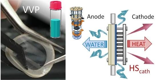
A passive regulation system for the water content has been developed and evaluated for a proton exchange membrane fuel cell. It is of particular relevance for micro-fuel cells, whose volume, weight and extra-consumption of fuel and power for subsidiary components must be kept to a minimum. This solution consists of a self-regulating humidity system implemented at the anode chamber that allows free water exchange with the environment through the surface of a gas-tight membrane. The micro-fuel cell, which is designed according to the patent WO2015025070A1, has been assembled and operated under completely passive conditions. The behavior of the anode humidity regulation system has been analyzed externally and in situ. The external part of the anode, where the humidity exchange with the environment takes place, has been isolated in a closed chamber and a hygrometer has been used to register the relative humidity in the zone near to the water exchange film. The results obtained from the operation of this innovative system are discussed in the light of the water permeation behavior of different Nafion membranes.

Graphical Abstract

1. Introduction

Accumulation of water at the anode is a common source of failure and malfunction in proton exchange membrane fuel cells, particularly when they are operated under anode dead-ended conditions [1,2]. Even when dry reactants are fed as fuel, water accumulation may lead to anode flooding by back-diffusion, especially at low current densities (below 0.1–0.2 A·cm−2) [3,4,5]. At higher current values, the electro-osmotic force and the higher cell temperature usually reduce water accumulation at the anode chamber.
Passive operation of air-breathing micro-fuel cells requires leaving auxiliary elements aside in order to maximize power and energy density, reducing the weight, volume and extra power consumption [6]. Dead-ended anode (DEA) operation is a common operational mode for portable fuel cells as it can simplify subsidiary systems, potentially avoiding flow meters and humidifiers. Its typical configuration usually employs a single pressure regulator before the hydrogen inlet to the cell and a purge valve after the anode outlet. However, DEA operation usually leads to a gradual voltage loss, mainly due to water accumulation at the anode.
Several approaches have been developed to avoid anode flooding and mitigate its irreversible and deleterious effects [1,7,8]. Sequential purging is often applied to remove the accumulated water (and nitrogen) during DEA operation. This solution relies on pressure regulation to supply the necessary hydrogen to maintain the electrochemical reaction, but it needs to be optimized to limit the fuel release during the periodical flush [9,10]. Opening the purge valve releases not only water, but a non-negligible amount of fuel, which reduces its utilization percentage. This is an especially relevant issue for portable systems, in which fuel saving is crucial to minimizing their dimensions.
In 2013, CIEMAT patented a new hardware configuration for an air-breathing PEM fuel cell to be operated in a completely passive mode, even without anode purging [11]. The invention relates to a small fuel cell operating with dry H2, which is fed at constant backpressure under dead-ended anode mode, and natural air convection capable of ca. 100% fuel utilization. Such an anode is able to work with 100% faradaic efficiency (stoichiometry λ = 1.0), which is a key issue to increase the autonomy of the application. The particular anode gas-tight configuration allows for continuous water permeability, which notably reduces the adverse consequences of fuel starvation by flooding.
Although it is well known that Nafion is an efficient membrane for proton transport associated with the polymer water content [12,13], there is a lack of studies regarding its performance for selective water and steam permeation driven by the chemical gradient developed across the membrane [14,15]. Determining the water permeation flux through different Nafion membranes is critical to optimizing the passive water regulation system in this new design. Therefore, different Nafion membranes with thicknesses in the range between 25 and 183 mm have been evaluated. The applicability of the developed self-regulating system and the operation conditions in this new fuel cell anode configuration have been analyzed in detail, considering its limitations and advantages.

2. Materials and Methods

2.1. Ex-Situ Permeability Tests

The permeation behavior of different Nafion membranes has been evaluated. Two different Nafion solution cast films, N211 and N212, were used for passive water permeation under natural convection conditions [16]. Some experiments were also performed with an extrusion cast N117 membrane as reference for comparison [17].
The nomenclature of the Nafion films usually indicates the polymer equivalent weight in the first figures (N117, 1100 g·mol−1 EW) and its thickness in mils in the last one, i.e., 0.001” (25 μm) in N211, 0.002” (50 μm) in N212, and 0.007” (183 μm) in N117. All these membranes have the same equivalent weight of 1100 g·mol−1, although membranes N211 and N212 are prepared by solution cast, whereas N177 is manufactured by extrusion [16,17].
Two different types of test were performed: from liquid phase to vapor phase (liquid–vapor permeation (LVP)) and from vapor phase to vapor phase (vapor–vapor permeation (VVP)). Measurements were carried out in glass vials filled with 10 mL distilled water and sealed with the corresponding membrane. Both LVP and VVP tests were performed at constant temperature under natural convection conditions. A compact climatic chamber able to control temperature and humidity (CCK model, Dycometal) was used for the measurements. For LVP tests, vials were placed in inverted position with the water lying directly over the membrane. A minimum period of 19 h was elapsed between weight measurements in order to reduce the relative error in them. Figure 1 shows some images and a scheme for the vials’ set-up.
Nafion membranes were assembled and mounted on perforated vial screw cups between silicone sealing joints. Membranes and joints were cut to the required size with a CO2 laser cutting machine (Gravograph LS 100) in order to obtain a good fitting inside the vial screw caps and a gas-tight seal. The vial sealing was tested with non-perforated silicone films. The permeation surface area of the membranes was 0.93 cm2. Before tests, Nafion membrane discs were pretreated in a H2SO4 0.5 M solution at 80 °C for 1 h, then immersed in distilled deionized water and finally dried at ambient temperature. Three vials were assembled with each one of the membranes to ensure reproducibility. The mass of each vial was measured before and after the permeation period at a fixed temperature in the range between 25 and 80 °C. Water flux and permeance were estimated for the different samples.

2.2. Fuel Cell Tests

2.2.1. Fuel Cell Description

A CIEMAT air-breathing PEM fuel cell (AB-PEMFC) round prototype based on WO2015025070A1 was used for the experiments [11,18]. The anode chamber consists of a circular PEEK plate with lateral gas fittings for fuel inlet and outlet. One of the faces of the plate allows for the assembly of the all the passive air-breathing fuel cell components in the order: the anode grid collector, the anode gas diffusion electrode (GDE), the proton exchange membrane electrolyte (Nafion NRE212), the cathode GDE, the cathode collector grid and a pinned plate for compression and high air accessibility. The other face of the anode plate is isolated from the ambient by a Nafion film permeable to water, which is fitted to the anode by another perforated plate of the same material. A scheme of the cell is presented in Figure 2. The cell operates under dead-ended anode mode fed with a small H2 overpresure (0.5–0.7 bar). The gas outlet at the anode is only open for initial purging of the chamber to remove air before operation. The H2 flow at the inlet corresponds to the amount of converted H2 into H2O. The amount of water accumulated at the anode by back diffusion from the cathode is expected to be partially permeated to the environment by the water permselective membrane fixed at the external anode side (see its detail in the inset in Figure 2). Consequently, when there is no demand load, there is a static hydrogen atmosphere at the anode, whose relative humidity is mainly determined by the water permeation through the Nafion film at the backing of the anode chamber.

2.2.2. In Situ Permeation Tests

In order to determine the rate of water exchange in the anode chamber with the ambient through the external part of the cell, a zipper gas-tight plastic bag was assembled between silicon seals with the anode external plate component. The isolated anode external chamber was equipped with fittings for a carrier gas inlet and outlet and a temperature and gas humidity sensor (PCE 313A). A small flow rate of nitrogen initially set to 0.03 mL·s−1 was used to simulate the exchange with a static and closed external environment. Then, higher flow rates were applied to analyze the cell behavior. Figure 3 shows images of the cell assembly for humidity permeation measurements.
The cell was fed with dry pure H2 under dead-ended anode mode using a three-way manual valve at the fuel outlet. Before the tests, the anode chamber was purged with a continuous gas flow to the remove air inside. Then, the outlet valve was closed, and the anode was connected to a hydrogen pipeline through a pressure-reducing regulator. The overpressure at the cell inlet was set to 0.5–0.7 bar. During cell operation, the H2 flow observed at the gas inlet corresponded exactly to the electrochemical cell conversion (i.e., no flow at OCV, and increasing H2 flow at increasing current demand), with 100% fuel utilization and without periodical purges. The cell was operated at ambient conditions without external heating, and the temperatures at the anode and the cathode were measured as a function of time. They were observed to strongly depend on the demand load.
A potentiostat/galvanostat (Metrohm Autolab PGSTAT302N) equipped with a booster unit was used for cell control. Chronoamperometric stages at different voltages were applied cyclically in steps of 0.1 V. Electrochemical impedance spectroscopy analyses were performed in order to analyze the cell behavior. Impedance responses were obtained under potentiostatic mode with a frequency response analyzer (FRA) module. For the experiments, the cells were maintained at each constant voltage during a 200 s period. Then, the amplitude of the AC signal was set to 10 mV and the frequency sweep range to 15,000–0.1 Hz.

3. Results and Discussion

3.1. Permeability Tests on Nafion Membranes

In this study, water permeation through Nafion membranes was studied under natural air convection conditions. It must be noted that this type of measurement is highly dependent on the air flow near the membrane, which determines the water partial pressure difference across the films. By considering the absence of an induced flow of air, the dispersion in the measurements can be attributed to small variations in the air flow near the membrane surface.
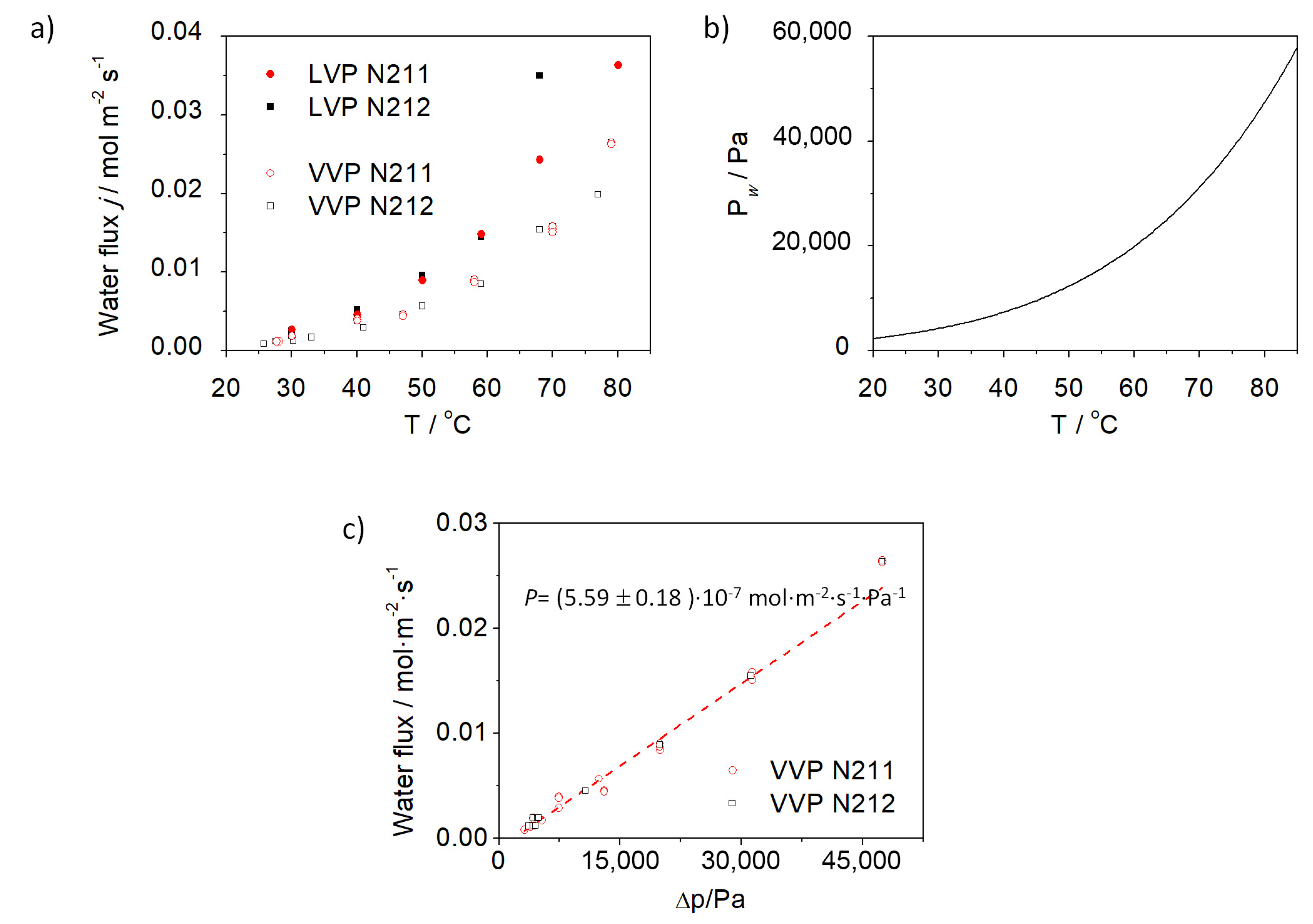
Permeation tests have revealed a slightly higher water flux in Nafion films for LVP than for VVP, since the hydration degree of the membranes is determinant of the permeation rate. As shown in Figure 4a, the VVP flux is very similar for N211 and N212, despite their difference in thickness. In the case of LVP, the water flux at ambient temperature is similar to that of VVP, but increases faster for both membranes, mainly at temperatures above 40 °C, and especially for N212 above 60 °C. The higher water flux under LVP than under VVP conditions is in agreement with the previous results reported by Adachi et al. on NRE211 at 70 °C [14].
Water flux through Nafion membranes increases exponentially with temperature, similarly to the water vapor pressure. Accordingly, it can be observed in Figure 4c that the VVP flux varies linearly with the water partial pressure difference between both sides of the membrane. The water vapor pressure difference values were estimated from the temperature and relative humidity values inside the vial and at the external side of the Nafion film. The slope of this plot (Figure 4c) allows for estimating a permeance value of (5.59 ± 0.18) × 10−7 mol·m−2·s−1·Pa−1 for N211 and N212 membranes under VVP (1669 ± 54 GPU), and reveals that the membrane thickness is not determinant of the VV permeation flux under natural convection conditions.
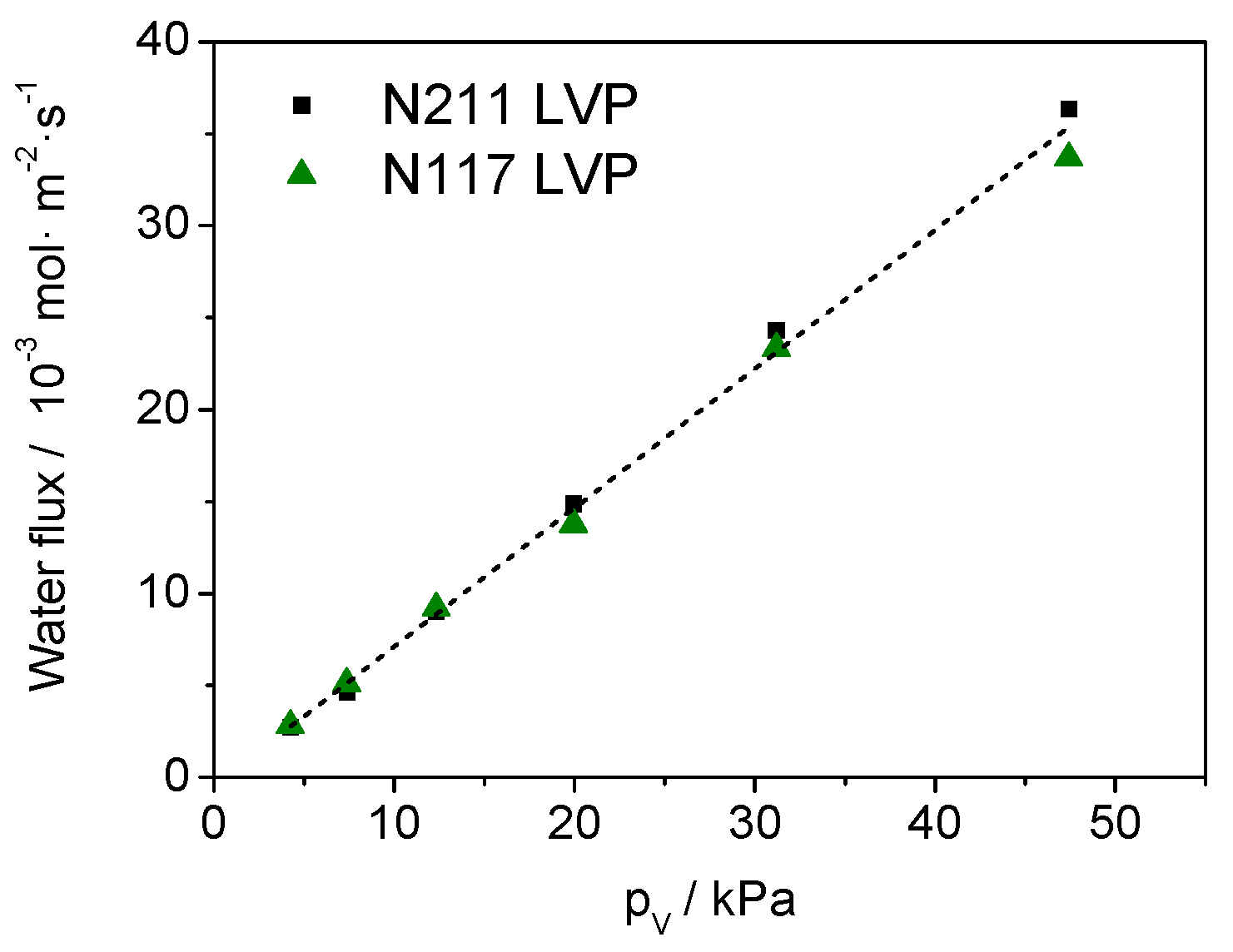
Under LVP and natural convection conditions, the permeance for N211 and N212 increases up to (7.89 ± 0.08) × 10−7 mol·m−2·s−1·Pa−1 (2355 ± 24 GPUs). To verify that the thickness of the membrane does not determine the permeation flow under these conditions, and that water permeation mainly depends on the membrane surface and the air convection, some additional experiments were performed on N117 for comparison with the thinnest membrane (N211). LVP experiments in Figure 5 indicate that the water permeation flux across Nafion films of different thicknesses (183 μm for N117 and 25 μm for N211) are very similar. Few studies can be found in the literature regarding water permeation flux in Nafion membranes under similar conditions [19,20,21,22], but the conclusions of Majsztrik et al. [20,21,22] and Adachi [14,19] support these results.
According to these results, the thickness of Nafion films is not a relevant parameter when these components are applied as water permselective membranes to regulate the anode chamber humidity. Nafion wetting experiments have shown that the membrane surface is hydrophobic when contacting water vapor, but becomes hydrophilic in contact with the liquid. This effect has often been explained by the restructuration of the polymer chain [23]. As a matter of fact, these permeation fluxes can be improved by applying a sweep flow of dry gas at the other side of the membrane. By using a Nafion extruded tube with 2.18 mm ID and 304 μm of thickness, filled with ultrapure water, an external flow of dry N2 is able to extract water at enough of a permeation rate to reach 100% RH up to flow rate values of 10−2 L·s−1 (Figure 6). Above that flow rate, the amount of permeated water under LVP conditions reaches a plateau. The internal surface of the tube for water permeation is estimated in 6.9 cm2. For this Nafion tube length of 10 cm, the estimated maximum flux permeated at room temperature is ca. 1.46 × 10⁻² mol·m−2·s−1.
These results indicate that water permeation through Nafion membranes mainly depends on the water activity at both sides of the membrane as the main driving force. The higher the sweeping flow rate, the larger the amount of permeated water. When the sweep gas flow rate is so high that the water permeation rate is not enough to saturate the external gas stream, the maximum permeation rate of the Nafion membrane is reached. Accordingly, in order to design a passive system for water regulation at the anode chamber based on Nafion membranes, the membrane thickness was not considered as a relevant parameter. The temperature in the anode near the permeation surface and the air convection around this area are assumed to be the critical parameters to control the air-breathing PEMFC.

3.2. Evaluation of the Self-Regulation Humidity Anode under Fuel Cell Operation

An N212 was used for the assembly of the AB-PEMFC to analyze its performance under real operation conditions. The passive air-breathing fuel cell was operated cyclically by controlling the cell voltage between 0.8 and 0.0 V in steps of 15 min of duration. The operation parameters registered during operation are compiled in Figure 7a. The current demand in the cell originated instantaneously a fast rise in relative humidity in the external anode environment, from 40% to 80–90%, which was continuously swept with a very low nitrogen flow rate of 0.03 mL·s−1 to simulate a static atmosphere under natural convection conditions (Figure 7b1). The sensor near the anode external side also registered an increase in temperature in that zone due to the heating of the cell when increasing electric current demand. After some hours, condensed water drops were observed at the colder walls of the bag containing the closed environment of the external anode water permeable chamber (see Image b.2 in Figure 7). This is a clear indication of the anode working as a water-permeable chamber in full dead-end mode.
The effect of the sweep gas flowrate to induce humidity removal from the anode chamber was analyzed. As shown in Figure 8a, the increase in the sweep flow rate up to 1.67 mL·s−1 had no significant impact on the extracted current or the temperature registered by the sensor at the anode wall. However, it had a large impact on the analyzed relative humidity at the anode external chamber, particularly at high current demands, since relative humidity values above 85% were obtained at the maximum cell current, whereas the minimum decreased to 40% at cell voltages of 0.8 V.
The percentage of the water instantaneously generated in the cell that can be extracted at once through the external surface of the anode chamber has been estimated, and is presented in Figure 8b. The higher the sweep gas flowrate, the higher the extraction effectiveness. A small flow of 0.03 mL·s−1 is not able to remove all the water extracted from the anode closed environment, and is finally condensed at the cooler walls of the external bag, as shown in Figure 7b2. This situation would simulate natural convection conditions in an environment of ca. 100% relative humidity.
A drier and more open environment can favor water extraction. Under a drier environment, which can be simulated by increasing the anode external N2 flowrate, the amount of water extracted through the anode can be estimated to be around 15–20% of that produced by the cell (Figure 8b).
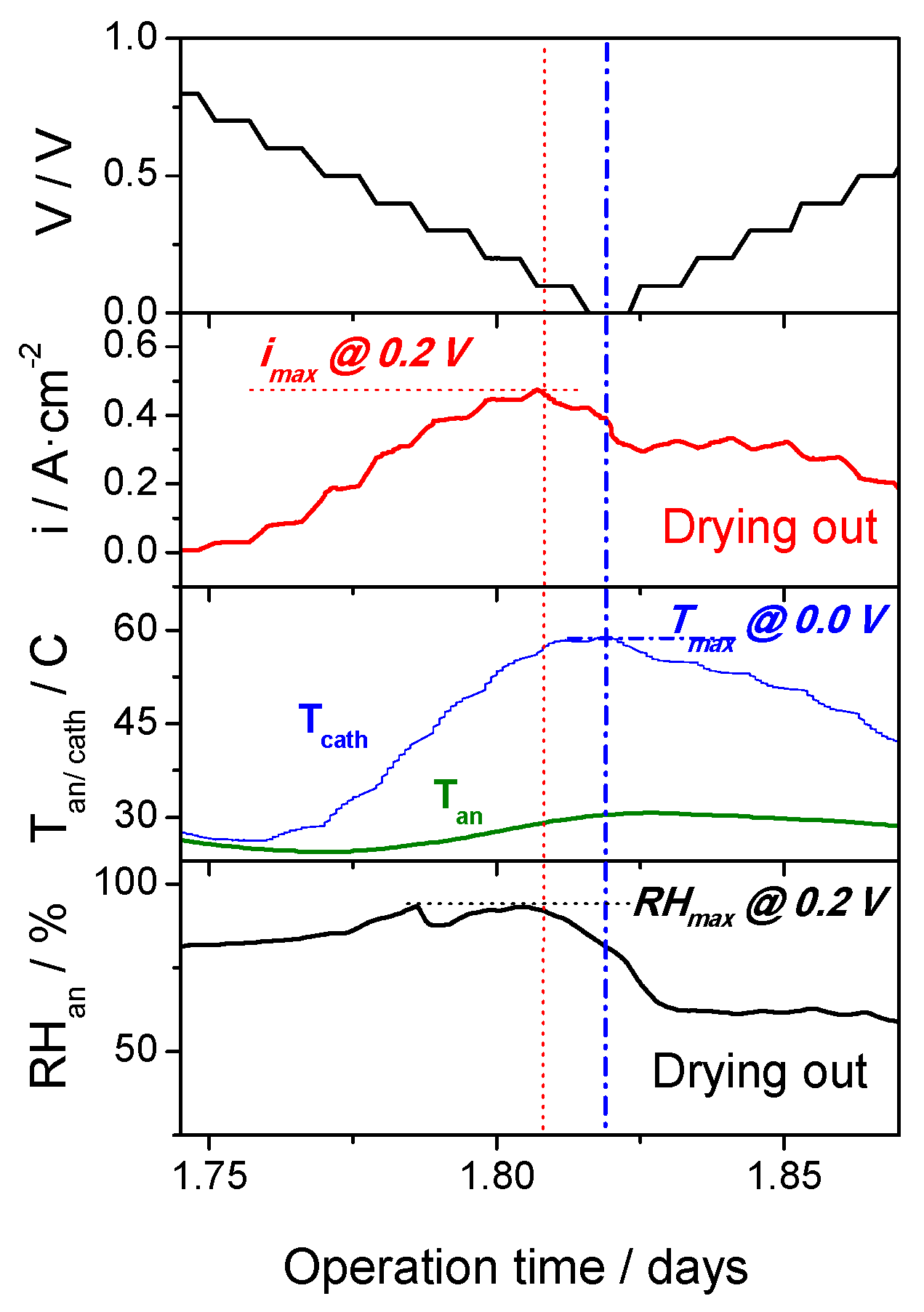
A detailed analysis of the cell behavior using a high sweep gas flowrate of 1.67 mL·s−1 reveals interesting details about the internal processes taking place in the cell. In Figure 9, it can be observed that the maximum current density in the cell is not obtained at the minimum voltage (0.0 V), but at 0.2 V. The cathode temperature in the heatsink at the cathode was also registered. At the lowest cell voltage (below 0.2 V), the cathode temperature reached a maximum (58 °C), which is shifted in time as compared to the maximum current density. It is curious to observe that the relative humidity at the anode external surface closely follows the pattern of the current density instead of that of the cathode temperature at the heat sink. This can be explained by an excessive drying out of the membrane-electrode assembly (MEA) at the maximum cell temperature. According to these results, it can be deduced that the shoulder observed for the current density in its cycling profile is due to the excessive drying-out of the MEA, which limits the cell performance. From this standpoint, a better distribution of the heat produced towards the anode chamber could improve the cell performance and avoid excessive temperatures in some zones.
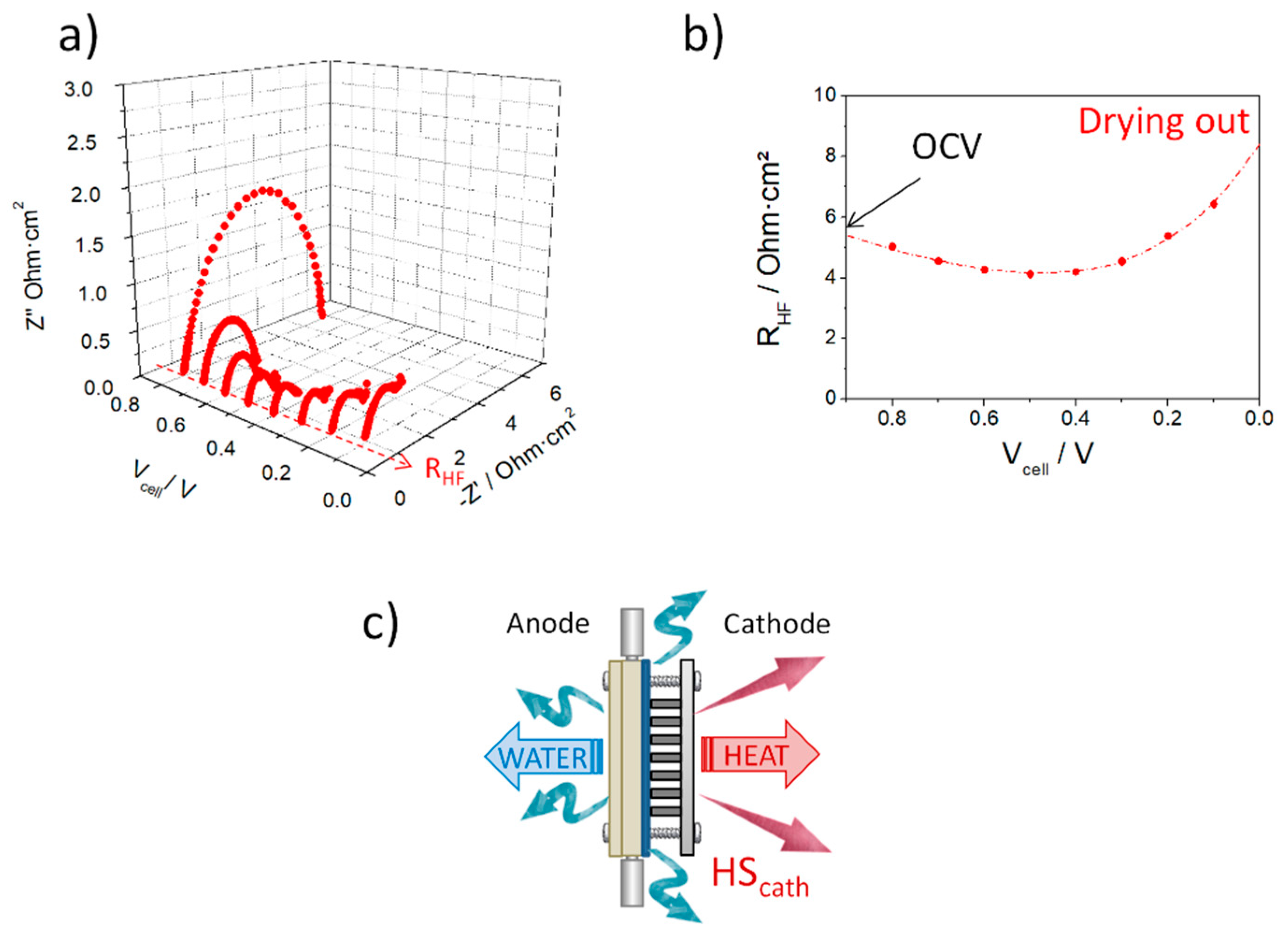
Figure 10 shows the Nyquist plots obtained for the cell in the range of voltages from 0.8 to 0.1 V. It can be qualitatively observed that the large charge transfer resistance at cell voltages close to that of the open circuit decreases as the current demand increases at intermediate cell voltages, and the cell temperature rises. Under those conditions, the cell generates water, which contributes to a better membrane humidification and improved cell performance. At high current demands and low cell voltage, the charge transfer resistance increases moderately, probably due to mass transport limitation processes. However, the most characteristic indication of the drying out of the polymer electrolyte membrane is the increase in the high-frequency resistance (RHF). The excessive increment of temperature in the cell at high current demands originates the electrolyte dehydration (Figure 10b).
Taking these results into consideration, the thermal resistance of the heatsink at the cathode is one of the components to redesign to better dissipate generated heat and distribute it towards the anode chamber to improve water redistribution throughout the cell [24]. Further studies are required in order to optimize the thermal management in the cell to maximize its performance.

4. Conclusions

The water permeation behavior of Nafion membranes has been analyzed under natural convection conditions. The obtained results reveal that the membrane thickness does not determine the water permeation flux in the tested thickness range from 25 to 183 microns, either for vapor–vapor permeation or liquid–vapor permeation. These values depend on the water activity at both sides of the membrane as driving force, which can be modified by the convection conditions at the permeation side.
By considering that the membrane thickness is not a key for passive water permeation, a N212 membrane has been evaluated in a completely passive air-breathing fuel cell fed with dry hydrogen in a dead-ended anode mode, and whose design allows for the humidity regulation at the anode chamber. The obtained results reveal that the ABPEMFC is able to operate continuously with this design, and constitutes a proof of concept of this operation mode. The operation of the cell under potentiostatic mode has shown that, at high overpotentials, the temperature of the cell rises, and the performance improves progressively. The cell is able to operate under anode dead-end mode in the long term without anode flooding. However, when the cell temperature is close to ca. 60 °C, the current decreases slightly as result of the drying out of the electrolyte membrane. Further work is required to optimize the cell design by adjusting the thermal resistance of the cathode heat sink and distributing the heat within the external structure towards the anode external chamber.

5. Patents

ES2466590 A1 (2014), WO 2015025070 A1 (2015). P. Ferreira-Aparicio, A.M. Chaparro. Fuel Cell.
Patent application number ES20190030869U 20190524. Martínez-Chaparro, A., Ferreira-Aparicio, P., Folgado-Martínez, M.A., Conde-López, J.J., De Rafael-Valdivia, D.; Miguel-Verdugo, F.J.

Author Contributions

Conceptualization, P.F.-A.; methodology, P.F.-A., P.A.P.-G., A.M.F.-S.; validation, P.F.-A, P.A.P.-G., A.M.F.-S.; formal analysis, P.F.-A., P.A.P.-G.; investigation, P.A.P.-G., A.M.F.-S.; resources, P.F.-A.; data curation, P.F.-A., P.A.P.-G; writing—original draft preparation, P.F.-A.; writing—review and editing, P.F.-A., P.A.P.-G., A.M.F.-S.; visualization, P.F.-A., P.A.P.-G.; supervision, P.F.-A., A.M.F.-S.; project administration, P.F.-A.; funding acquisition, P.F.-A. All authors have read and agreed to the published version of the manuscript.

Funding

This research was funded by the SPANISH MINISTRY FOR SCIENCE AND INNOVATION and by the EUROPEAN REGIONAL DEVELOPMENT FUND (ERDF) from the EU, grant number ENE2015 70417-P (E-LIG-E).” A. Fernández-Sotillo was awarded a pre-doctoral grant from the SPANISH MINISTRY FOR SCIENCE AND INNOVATION under contract BES-2016-077336. The APC was funded by SPANISH MINISTRY FOR SCIENCE AND INNOVATION and by the EUROPEAN REGIONAL DEVELOPMENT FUND (ERDF) from the EU, grant number PID2019-110896RB-I00 (ELHYPORT).

Acknowledgments

The authors acknowledge the Spanish Ministry for Science and Innovation and the European Regional Development Fund (ERDF) from the EU for funding under contracts ENE2015 70417-P (E-LIG-E), PID2019-110896RB-I00 (ELHYPORT), and for a pre-doctoral grant under contract BES-2016-077336.

Conflicts of Interest

The authors declare no conflict of interest. The funders had no role in the design of the study; in the collection, analyses, or interpretation of data; in the writing of the manuscript, or in the decision to publish the results.

References

  1. Luo, L.; Huang, B.; Cheng, Z.; Jian, Q. Improved water management by alternating air flow directions in a proton exchange membrane fuel cell stack. J. Power Sources 2020, 466, 228311. [Google Scholar] [CrossRef]
  2. Ji, M.; Wei, Z. A review of water management in polymer electrolyte membrane fuel cells. Energies 2009, 2, 1057–1106. [Google Scholar] [CrossRef] [Green Version]
  3. Chen, J. Degradation, Efficiency, and Equilibrium of a Dead-Ended Anode Fuel Cell. Ph.D. Thesis, University of Michigan, Ann Arbor, MI, USA, 2013. [Google Scholar]
  4. Chen, B.; Ke, W.; Luo, M.; Wang, J.; Tu, Z.; Pan, M.; Zhang, H.; Liu, X.; Liu, W. Operation characteristics and carbon corrosion of PEMFC (Proton exchange membrane fuel cell) with dead-ended anode for high hydrogen utilization. Energy 2015, 91, 799–806. [Google Scholar] [CrossRef]
  5. Ge, S.; Wang, C.-Y. Liquid Water Formation and Transport in the PEFC Anode. J. Electrochem. Soc. 2007, 154, B998. [Google Scholar] [CrossRef]
  6. Ferreira-Aparicio, P.; Conde, J.J.; Chaparro, A.M. 2-Fundamentals and components of portable hydrogen fuel-cell systems. In Portable Hydrogen Energy Systems; Ferreira-Aparicio, P., Chaparro, A.M.B.T.-P.H.E.S., Eds.; Academic Press: London, UK, 2018; pp. 15–39. ISBN 978-0-12-813128-2. [Google Scholar]
  7. Ziegler, C.; Schmitz, A.; Tranitz, M.; Fontes, E.; Schumacher, J.O. Modeling planar and self-breathing fuel cells for use in electronic devices. J. Electrochem. Soc. 2004, 151, A2028–A2041. [Google Scholar] [CrossRef]
  8. Liu, W.; Wan, L.; Liu, J.; Zhao, M.; Zou, Z. Performance improvement of the open-cathode proton exchange membrane fuel cell by optimizing membrane electrode assemblies. Int. J. Hydrogen Energy 2015, 40, 7159–7167. [Google Scholar] [CrossRef]
  9. Chen, J.; Siegel, J.B.; Stefanopoulou, A.G.; Waldecker, J.R. Optimization of purge cycle for dead-ended anode fuel cell operation. Int. J. Hydrogen Energy 2013, 38, 5092–5105. [Google Scholar] [CrossRef]
  10. Matsuura, T.; Chen, J.; Siegel, J.; Stefanopoulou, A. Degradation phenomena in PEM fuel cell with dead-ended anode. Int. J. Hydrogen Energy 2013, 38, 11346–11356. [Google Scholar] [CrossRef]
  11. Chaparro, A.M.; Ferreira-Aparicio, P. WO2015025070—Fuel Cell. Available online: https://patentimages.storage.googleapis.com/19/d1/3c/93f911a503b2b3/WO2015025070A1.pdf (accessed on 7 November 2020).
  12. Weber, A.Z.; Borup, R.L.; Darling, R.M.; Das, P.K.; Dursch, T.J.; Gu, W.; Harvey, D.; Kusoglu, A.; Litster, S.; Mench, M.M.; et al. A Critical Review of Modeling Transport Phenomena in Polymer-Electrolyte Fuel Cells. J. Electrochem. Soc. 2014, 161, F1254–F1299. [Google Scholar] [CrossRef] [Green Version]
  13. Duan, Q.; Wang, H.; Benziger, J. Transport of liquid water through Nafion membranes. J. Memb. Sci. 2012, 392–393, 88–94. [Google Scholar] [CrossRef]
  14. Adachi, M.; Navessin, T.; Xie, Z.; Frisken, B.; Holdcroft, S. Correlation of In Situ and Ex Situ Measurements of Water Permeation Through Nafion NRE211 Proton Exchange Membranes. J. Electrochem. Soc. 2009, 156, B782. [Google Scholar] [CrossRef] [Green Version]
  15. Motupally, S.; Becker, A.J.; Weidner, J.W. Diffusion of Water in Nafion 115 Membranes. J. Electrochem. Soc. 2000, 147, 3171. [Google Scholar] [CrossRef]
  16. Fuel Cell Store Nafion NR211 and NR212 Ion Exchange Materials Solution Cast Membranes. Available online: https://www.fuelcellstore.com/spec-sheets/chemours-nafion-211-212-spec-sheet.pdf (accessed on 7 November 2020).
  17. Fuel Cell Store—Nafion 115, 117, 1110 Ion Exchange Materials. Available online: https://www.fuelcellstore.com/spec-sheets/chemours-nafion-115-117-1110-spec-sheet.pdf (accessed on 7 November 2020).
  18. Folgado, M.A.; Conde, J.J.; Ferreira-Aparicio, P.; Chaparro, A.M. Single Cell Study of Water Transport in PEMFCs with Electrosprayed Catalyst Layers. Fuel Cells 2018, 18, 602–612. [Google Scholar] [CrossRef]
  19. Adachi, M. Proton Exchange Membrane Fuel Cells: Water Permeation Through Nafion Membranes. Ph.D. Thesis, Simon Fraser University, Burnaby, BC, Canada, 2010. [Google Scholar]
  20. Majsztrik, P.W. Mechanical and Transport Properties of Nafion® for PEM Fuel Cells: Temperature and Hydration Effects; Princeton University: Princeton, NJ, USA, 2008. [Google Scholar]
  21. Zhao, Q.; Majsztrik, P.; Benziger, J. Diffusion and interfacial transport of water in Nafion. J. Phys. Chem. B 2011, 115, 2717–2727. [Google Scholar] [CrossRef] [PubMed]
  22. Majsztrik, P.; Bocarsly, A.; Benziger, J. Water permeation through nafion membranes: The role of water activity. J. Phys. Chem. B 2008, 112, 16280–16289. [Google Scholar] [CrossRef] [PubMed]
  23. Goswami, S.; Klaus, S.; Benziger, J. Wetting and Absorption of Water Drops on Nafion Films. Langmuir 2008, 24, 8627–8633. [Google Scholar] [CrossRef] [PubMed]
  24. Ismail, M.S.; Ingham, D.B.; Hughes, K.J.; Ma, L.; Pourkashanian, M. Thermal modelling of the cathode in air-breathing PEM fuel cells. Appl. Energy 2013, 111, 529–537. [Google Scholar] [CrossRef]
Figure 1. (a) 1. Glass vial with an open screw cap for water permeation measurements through Nafion films; 2. Detail of the open screw cap; 3. N212 membrane sandwiched between silicone joints for the assembly; (b) vials position for liquid–vapor permeation (LVP) and for vapor–vapor permeation (VVP) measurements.
Energies 13 05880 g001
Figure 2. Exploded view of the passive air-breathing single PEM fuel cell based on WO2015025070A1. Inset: detail of the anode plates to fix the water permselective membrane for passive water management.
Energies 13 05880 g002
Figure 3. (a) External part of the anode chamber for selective water permeation in a completely passive air-breathing fuel cell; (b) Cell ready for operation with a sensor for temperature and relative humidity at the external anode surface, where a sweep gas is fed; (c) Image of the internal surface of the anode plate assembly for determining the water exchange with the environment; (d) Scheme of the air-breathing PEM fuel cell assembly for the analysis of the anode chamber during operation.
Energies 13 05880 g003
Figure 4. (a) Water permeation flux through N211 and N212 film under liquid–vapor permeation (LVP) and vapor–vapor permeation (VVP) conditions as a function of the temperature; (b) Water vapor pressure as a function of the temperature; (c) Water flux measurements for VVP in N211 and N212 film under natural convection of air.
Energies 13 05880 g004
Figure 5. Water permeation flux through N211 and N117 films as a function of the water vapor pressure under liquid–vapor permeation (LVP) conditions and natural convection of air.
Energies 13 05880 g005
Figure 6. Water flux permeated through a Nafion tube (0.0086” ID, 0.012” thickness) under liquid-vapor permeation (LVP) conditions at room temperature using a dry N2 sweep flow in an external shield formed by a PTFE tube of ¼” OD.
Energies 13 05880 g006
Figure 7. (a) Operation parameters of the novel air-breathing PEM fuel cell assembled to analyze the humidity released from the dead-end anode chamber: cell voltage, cell current, temperature measured at the sensor in the bag, relative humidity registered by the sensor near the water selectively permeable side of the anode chamber with a sweep nitrogen flow rate in the hermetically closed bag of 0.03 mL·s−1. (b) Image of the assembly for relative humidity and temperature measurements at the external anode side: (b1) before operation, (b2) after 4 hours under continuous operation using a sweep gas flow of 0.03 mL·s−1 inside the bag.
Energies 13 05880 g007
Figure 8. (a) Operation parameters of the CIEMAT ABPEMFC assembled to analyze the humidity released from the dead-end anode chamber: cell voltage, cell current density, temperature measured at the sensor in the bag, relative humidity registered by the sensor near the water selectively permeable side of the anode chamber with increasing nitrogen flow rate to sweep the hermetically closed bag (0.03 mL·s−1 at the beginning of the test, 0.25 mL·s−1 after 1 day operation, 1.67 mL·s−1 after cycling during 1.75 days); (b) estimation of the percentage of the water instantaneously generated at the cell at 0.2 and at 0.45 A·cm² that has been extracted by the external anode chamber surface at different sweep flowrates.
Energies 13 05880 g008
Figure 9. Operation parameters of the cell with a dry nitrogen stream to flush the external anode chamber with a flow rate of 1.67 mL·s−1.
Energies 13 05880 g009
Figure 10. (a) Electrochemical impedance spectra registered at different voltages for a commercial MEA assembled in the ABPEMFC design with a heat sink at the cathode; (b) High-frequency resistance of the Nyquist plots series as a function of the cell voltage; (c) Scheme of the cell configuration showing the flows of heat and water.
Energies 13 05880 g010
Publisher’s Note: MDPI stays neutral with regard to jurisdictional claims in published maps and institutional affiliations.