1. Introduction
Nuclear power generation involves the use of heat from nuclear reactions to produce high-pressure steam to work the steam turbines and produce electricity. Recently, more than 400 reactors have been operating around the world, most of which have capacities of about 1000 MWe. Due to the need for large amounts of heat sinks and local not-in-my-backyard (NIMBY) responses, reactors have been installed in remote regions outside cities. Thus, in order to transport electricity from nuclear power plants into cities, extensive grid networks have been distributed. In addition, if a large-capacity nuclear power plant fails, cities or factories that use electricity from the affected power plant may experience blackouts. Moreover, a few years ago, the Fukushima Daiichi nuclear disaster occurred. Even now, public access near the Fukushima Daiichi nuclear power plant is limited, and decontamination is still in progress. Despite recognizing the importance of nuclear energy as the main solution for global warming and achieving CO
2 reduction objectives, controversy still exists regarding the safety of the nuclear power plants, waste disposal, and non-proliferation due to the Fukushima accident. Hence, the nuclear societies worldwide have been developing new and innovative reactors with the objective of guaranteeing safety under any circumstances and in natural disasters. Due to the increment of the requirements for the nuclear safety and security [
1], there are a lot of research and technology developments to improve the safety, sustainability, efficiency, and cost in nuclear power plants (e.g., Generation IV reactors [
2,
3], Thorium reactors [
4], and small modular reactors [
5,
6]).
Currently, the research on small modular reactors (SMRs) is increasing rapidly owing to the advantages of these devices. SMRs can be used for multipurpose applications and may well be safer than large-capacity reactors [
5,
6,
7]. Some specific applications of SMRs are ship propulsion [
8], small-scale power generation [
9], desalinization [
10], and district heating [
11]. In light of climate change and the Fukushima nuclear accident, stricter regulations for fossil fuels and strengthened safety requirements for nuclear reactors have been put in place [
12,
13]. Therefore, many countries are paying closer attention to the development of SMRs to meet their expansion expectations regarding the market of small-scale nuclear power plants suitable for small power grids. In particular, SMR technology has a power generation scale of about 100 MWe, which is about 1/10 of that of the existing large commercial nuclear power plants. In most SMR designs, by moving the steam generators, pressurizers, and reactor coolant pumps into the reactor vessel, the entire complex nuclear reactor cooling system is compressed into a cylindrical module.
Figure 1 shows representative pressurized light-water SMRs. An SMR is generally composed of an integral-type reactor whose pressure vessel contains the primary system (such as steam generators), a pressurizer, and the core and main coolant pumps. The withdrawal of the pipes connecting the primary system prevents large-break loss-of-coolant accidents (LOCAs) [
14].
This study focused on the natural circulation in pressurized light-water SMRs as well as on the design of SMRs without reactor coolant pumps (RCPs).
Figure 2 shows a schematic of an SMR without RCPs, which is similar to CAREM-25 designed in Argentina [
15].
In this reactor type, the reactor core is located in the upper part of the vessel to produce heat, while the steam generator (SG) is positioned in the upper region to remove the generated heat. In an integral SMR, the reactor vessel (RV) contains all the primary systems and is the main part of the reactor coolant pressure boundary. The RV provides additional flow paths between the core and the SGs. The hot-water riser supplies flow paths heated by the reactor core, through which the coolant goes upward. To control the system’s pressure, a pressurizer is located at the top head of the RV. The aim of this study was to evaluate the effect of RV and riser SG tubes with various pitches and relative diameters on the performance of pressurized light-water SMRs driven by natural circulation. Now, the basic parameters of SMRs driven by natural circulation are explained; however, as the SMR pressurizer is not located in the main flow path of the primary coolant, this component is not considered herein. One of the main advantages of SMRs is that they can be transported by truck, train, or barge after being manufactured. Taking this into account, the RV length and diameter must be set below 13.8 and 2.5 m, respectively. In addition, the SMR electric power capacity should not exceed 300 MWe. Assuming that the efficiency of an SMR power plant is 33%, which is similar to that of a commercial power plant, the core power should be below 1000 MWth. In this study, the core power at full power conditions was assumed as 200 MWth. The reactor core consisted of 37 fuel assemblies with a 17 × 17 fuel rod array. The core diameter was approximately 1.75 m, and the active core length was 2.0 m. To supply superheated steam to the turbine, the SG was assumed to be a straight tube and was located between the riser and the RV. The SG tube array was organized in an equivalent triangular pattern (see
Figure 3).
Therefore, the primary coolant flows outside the tubes, and its heat is removed by the secondary feed water, which passes through the tubes and generates superheated steam. A preliminary SG-sizing evaluation showed that if the diameter of the SG tubes is 20 mm, the SG needs 6000 eight-meter-long tubes.
Figure 3 shows the basic configuration and dimensions used to analyze the SMR’s performance. If different values are set, the RV diameter (D) and the riser diameter (d) would rely on the SG tube pitch (S). Most importantly, to arrange the 6000 SG tubes (20 mm in diameter and 8 m in length), the reference array should have a 30 mm tube pitch, which corresponds to 1.5 times the tube diameter. The reference array of the 30 mm tube pitch was set to have the same diameter as the RV and the riser in both the upper and lower parts. For the cases with S = 20 and 40 mm, D and d can be modified depending on fixed diameters. Thus,
Figure 4a,b show SMR configurations with the different SG tube pitches depending on d and D, respectively. The basic parameters of these SMR configurations for different SG tube pitches are listed in
Table 1 and
Table 2.
2. Analysis Method
Natural circulation occurs due to the body force acting on a fluid with a density gradient. The net effect is the buoyancy force, which causes natural circulation. In general, the density gradient is induced by a temperature gradient, and the body force is due to the gravitational field. Since the flow rate of natural circulation is generally much smaller than that of forced convection, the heat transfer rate from natural circulation is also small. However, to avoid the vibration from a rotary machine such as a pump or compressor, or to minimize the operating cost, natural circulation is often preferred over forced convection.
The flow in forced convection is imposed by external factors, whereas that in natural circulation occurs due to the buoyancy inside the fluid. The buoyancy is induced by the complex existence of a density gradient in the fluid and a body force proportional to the density. Even though the centrifugal force in a rotating fluid machine or the Coriolis force in the rotating motions of the air and oceans is also a volume force, the body force is usually gravity in practical situations. In addition, there are several methods in which a density gradient can occur in a fluid, but this density gradient comes from the presence of a temperature gradient. The densities of gases and liquids depend on the temperature and generally decrease with increasing temperature.
In this study, numerical calculations were conducted as an attempt to model buoyancy as a function of various simple geometric and hydraulic parameters during normal power generation. Especially, this study was focused on the natural circulation due to a density gradient caused by a temperature gradient and a body force caused by gravity. However, natural circulation does not always occur when a density gradient exists in a fluid in a gravitational field. If the temperature at the bottom is higher than that at the top, natural circulation can occur because the denser upper fluid descends and the less dense lower fluid rises. On the contrary, if the temperature at the bottom is lower than that at the top, natural circulation cannot occur. Therefore, when natural circulation is used to remove heat from the core of a nuclear power plant, a cooling machine is installed at a higher position than that of the hot core. In addition, the same method of generating natural circulation is used in SMRs.
2.1. Governing Equations
The equations describing the transfer of mass, momentum, and energy in natural circulation as well as forced convection are derived from the associated conservation principles. As the energy transfer from advection and diffusion is important, the inertial and viscous forces are highly important as well. Moreover, buoyancy plays a major role in natural circulation. In fact, it is these forces that sustain the flow. In particular, buoyancy-driven turbulent thermal transfer is an important effect in natural circulation. Turbulent flow is an unstable and chaotic motion that occurs when the viscous force to be stabilized is insufficient. At high Reynolds numbers, the natural instability that occurs in the flow is not attenuated and appears as a result of vortices of various sizes. To simulate turbulent flow accurately, a very small computational gird and very short time interval must be used, which inevitably requires excessive amounts of computer memory and computational time, causing difficulty in actual engineering calculations. Therefore, a simplified model that describes the effect of turbulence on the average flow characteristics is typically used. In this study, we adopted the k-ε turbulent model to simplify the turbulent flow, as shown in Equations (4) and (5).
Thus, in order to cope with the transport phenomena for the SMR in
Figure 2, the governing conservation equations for continuity, momentum, and energy, and the k-ε turbulent model were employed in the forms presented below, as provided in the user’s guide of the computational fluid dynamics (CFD) software ANSYS [
16].
Turbulent kinetic energy equation (k):
Turbulent dissipation equation (ε):
In Equations (1)–(5), E is the internal energy, is the gravitational acceleration, is the specific enthalpy of component i, k is the turbulence kinetic energy, keff is the effective thermal conductivity, P denotes pressure, T denotes temperature, denotes velocity, µ is the dynamic viscosity, ρ is the density, is the mass flow rate, ε is the turbulent dissipation rate, and is the stress tensor.
2.2. Assumptions and Boundary Conditions
In the simulation performed in this study, the SMR was assumed to be a steady state because we wanted to observe whether natural circulation occurred sufficiently at a given heat power. Hence, the first terms in Equations (1)–(5), which are the differential terms for time, were excluded from the calculations.
To calculate the steady-state heat and mass transfer in the SMR, we used the commercial CFD software ANSYS. In this study, the primary coolant of the SMR was subcooled water-pressurized at 15.5 MPa (P
op), which regulated the pressure in the reactor, and the focus of this study was placed on this single phase. A two-dimensional numerical simulation was performed because of the asymmetric shape of the SMR (as shown in
Figure 5). Omitting the pressurizer, the RV top was assumed as a wall. In particular, since the purpose of this study was to evaluate the performance of natural circulation, it is important to note that the wall between the flow paths going up through the riser and down through the SG was treated as being in adiabatic conditions to prevent negative effects on the natural circulation. It was also assumed that all walls were adiabatic and that the core and the SG presented a uniform heat source and heat sink, respectively. It was considered that the total magnitude of the heat source in the core and the heat sink in the SG were identical, i.e., there were no heat losses. As for the reason to assume the uniform heat source and sink, this study was the first step to develop the SMRs in our community and to gain the insight as to whether it is possible to operate the SMRs with only natural circulation without a pump under the steady-state conditions. Surely, as the water on the secondary side undergoes a phase change into the steam, the heat transfer characteristics from the primary side to the secondary side are considered to be different from the uniform heat transfer characteristics used in this analysis. However, as for the overall amount of heat transfer, the heat received from the primary side should be accurately transferred to the secondary side for the heat management and the normal operation. Therefore, all design details of the devices for heat transfer to the secondary and the concrete computation models and calculation results will be promoted in the future works, and the heat transfer and the safety analysis under accident conditions considering the phase change of the secondary side will be included as well.
As it was significantly complicated to specify the wall boundary in the numerical simulation because of the real geometry of the core and the flow passage, the core and the SG tube bundles were considered porous media. Then, the flow passage was simplified as a channel flow governed by Darcy’s law with pressure drops, as illustrated in the following equation:
where parameters
α (permeability) and
C (inertia resistance factor) were obtained by using empirical data of the core [
17] and analyzing the numerical simulation data of the flow passing through the channel with the real SG tube bundle boundary configuration. The results are shown in
Figure 6. The calculation results for the core in
Figure 6a show that the pressure drop per unit length can be well interpolated into a quadratic equation for velocity, as indicated by Darcy’s law, like in Equation (6). The pressure drop for the SG tube bundle core in
Figure 6b also follows Darcy’s law. In particular, in
Figure 6b, it can be seen that the smaller the tube pitch, the greater the pressure loss for the corresponding velocity. From these calculation results, we obtained the coefficients
α and
C in Equation (6) to simplify the actual configurations for the core and SG tube bundles in the porous media.
3. Calculation Results and Discussion
The calculations were conducted under normal operating conditions. When the height of the reactor was fixed, the calculations were performed by changing the SG tube pitch (S), riser diameter (d), and RV diameter (D).
Figure 7 presents the velocity vector’s computed contours for the investigated SG tube pitches (S = 20, 30, and 40 mm). Specifically, when the riser diameter is constant,
Figure 7a shows the velocity contours according to the indicated SG tube pitches, which resulted in RV diameter changes. Further,
Figure 7b displays the velocity contours with the indicated SG tube pitches, which resulted in riser diameter changes. As expected, the velocities in the core and in the SG, which were modeled as porous media, are uniform, while the RV velocities near the top and bottom decrease sharply: this is owing to a flow direction change. Although the RVs and SGs with uniform diameter velocity vectors (S = 30 mm) present a uniform velocity, those with nonuniform diameter velocity vectors (S = 20 and 40 mm) present different characteristics between them. In the velocity contour for S = 40 mm shown in
Figure 7b, the hot water passes through the riser and the velocity increases sharply. This is caused by the coupled effect of the buoyancy force and a flow area contraction. Thus, sections with diameter changes should be eliminated, particularly by tapering or rounding, because the velocity changes sharply near nonuniform diameters, and this velocity change can negatively affect the natural circulation flow rate.
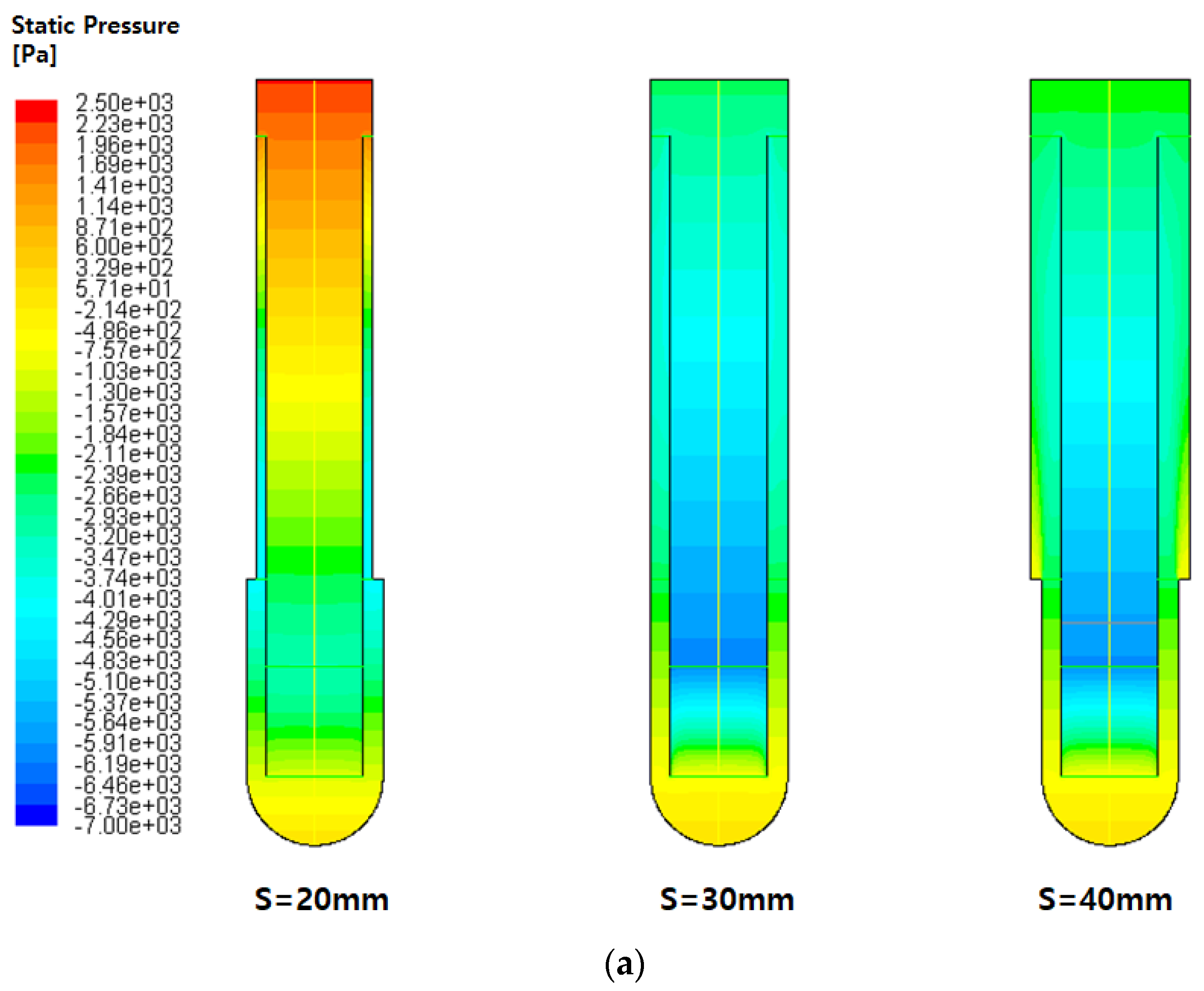
Figure 8 presents the static pressure contours. If the water is stationary, then the pressure obeys Equation (7).
Any particle with a non-zero vertical height will have different pressures on its top and bottom, with the pressure on the bottom being greater. This difference in pressure causes the upward buoyancy force. Thus, if the density is constant, the static pressure due to the buoyancy force decreases the bottom to the top. However, in a natural circulation loop, the density is not constant due to the temperature variations. In the S = 30 mm and S = 40 mm loops, the pressure decreases upwards. However, in the S = 20 mm loops, the pressure at the top is the greatest because the increase in density is larger than the increase in height in Equation (7). Moreover, because the S = 20 mm loop has to pass through very narrow spaces, inducing a large pressure drop, the residence time near the top becomes longer than it is in other loops, the top fluid becomes cold, and the density of the top fluid becomes high.
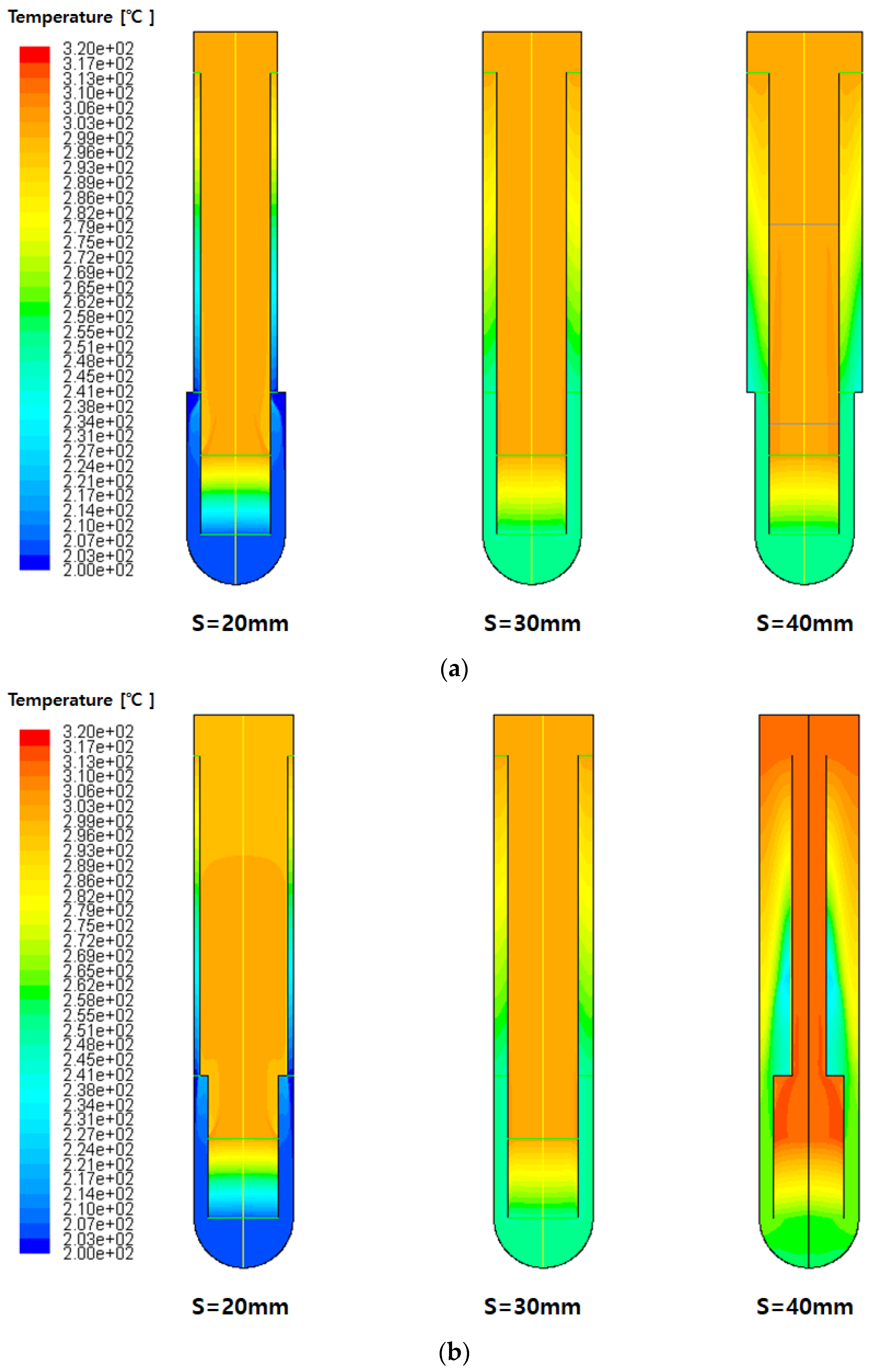
Figure 9 presents the temperature contours in the investigated SMRs. When the natural circulation loop is in a steady state and in a single phase, the differences between the highest temperature near the core and the lowest temperature near the SG can be represented by Equation (8) [
18].
where
R is the overall flow resistance,
β is the expansion coefficient, △
H is the height difference between the core center and the SG center, and
Cp is the specific heat. As the S = 20 mm loops present the largest
R values in the SG, the temperature differences therein are the largest (
Figure 9).
The temperature calculation results show that all loops have an equal maximum temperature (approximately 304 °C), except for the S = 40 mm loop in
Figure 9b, which has the largest maximum temperature (approximately 315 °C). That is because other loops can dissipate heat from the core in relatively large cross-sectional areas, but S = 40 mm in
Figure 9b has a small cross-sectional area and cannot sufficiently dissipate the heat. On the other hand, the S = 30 mm loops present the minimum temperature difference as well as the most uniform temperature distribution. This characteristic is evident because the flow velocity suddenly changes in other loops due to the change in the cross-sectional area, but in the S = 30 mm case, the cross-sectional area is the most uniform, so the change in flow velocity is small, and the temperature variation is the smallest.
Figure 10 shows the maximum, minimum, and average temperatures for the investigated SMRs, including the difference between the maximum and minimum temperatures. It seems that the maximum temperature (i.e., the core exit temperature) is not significantly affected by the RV and the riser diameters. However, the opposite is observed for the minimum temperature (i.e., the SG exit temperature) and consequently for the difference between the maximum and minimum temperatures. The minimum temperature near the SG is greatly affected by a variation in the SG tube pitch, which modifies the upper diameters of the RV and the riser. On the other hand, as the lower diameters of the RV and the riser are not changed, the maximum temperature near the reactor core remains unaltered. Hence, the calculation results for the temperature show that the cross-sectional area should be held constant if a uniform temperature is desired.
Finally, Equation (8) can be converted to express the mass flow rate, as follows [
18]:
The natural circulation mass flow rates are the performance indices for SMRs without RCPs.
R increases if S decreases, which leads to a decrease in the mass flow rate. The mass flow rate and core power values for the investigated SMRs are presented in
Figure 11. When the riser diameter is fixed, as shown in
Figure 11a, the S = 20 mm loop has the smallest flow rate, whereas the S = 30 and 40 mm loops present higher flow rates. Although the S = 40 mm loop has a greater SG tube pitch and lower flow resistance than those of the S = 30 mm loop, the mass flow rate in the former is influenced by additional sources of flow resistance, such as form losses caused by flow diameter changes. Particularly, if the RV diameter is fixed, as shown in
Figure 11b, the flow rate in the S = 40 mm loop with nonuniform diameters is lower than that in the S = 30 mm loop.
Based on the previously presented results, we can infer that to obtain a more uniform temperature distribution and a larger mass flow rate in SMRs, the reactor’s coolant passage diameters should be maintained as uniform as possible.
4. Conclusions
In this study, numerical simulations of SMRs were performed to determine the effect of the variation of the RV and riser diameters on the performance of natural circulation SMRs by investigating parameters such as the SG tube pitch. The governing conservation equations for continuity, momentum, and energy, and the turbulent (k-ε) model were solved to evaluate the natural circulation in SMRs without RCPs. In addition, in order to simplify the geometry of the SG tube bundles and core, which is quite complicated, we obtained the coefficients of Darcy’s law by calculating some periodic components and applied these coefficients to the porous media instead of directly simulating the SG tube bundles and core.
The calculated velocity contours show that the velocity is uniform in porous media such as the core and SG and that the velocity decreases sharply near the top and bottom due to the change of the flow direction. However, the velocity vectors obtained in the cases with non-uniform diameters show that the velocity increases more sharply when hot water passes through a narrower riser than through others. This behavior is induced by a coupled effect caused by both a buoyancy force and flow area contraction. In future work, it will be necessary to improve the design near intervals with changing diameters using tapping or rounding because the velocity near regions with non-uniform diameters changes sharply and such velocity changes can affect the natural circulation flow rate and locally cause critical heat flux and departure from nucleate boiling.
The simulation results indicated that the maximum temperature near the reactor core is not influenced by variations in the RV and riser diameters; however, variations in the SG tube pitch and in the relative upper RV and riser diameters greatly affect the minimum temperature near the SG. Although the flow rate increases with increasing the SG tube pitch, it can be reduced by form losses caused by flow diameter changes. In conclusion, to obtain a more uniform temperature distribution and a larger mass flow rate in the reactor, it is recommended to maintain the coolant passage diameters as uniform as possible.
Additional research on SMR sizing will be conducted using nonuniform heat sources and heat sinks, under different local heat transfer rates obtained from experimental results. This investigation will focus on the thermal-hydraulic phenomenon in SMRs, which is only driven by natural circulation.


