Development of Selective Acidizing Technology for an Oil Field in the Zechstein Main Dolomite


Abstract
:1. Introduction
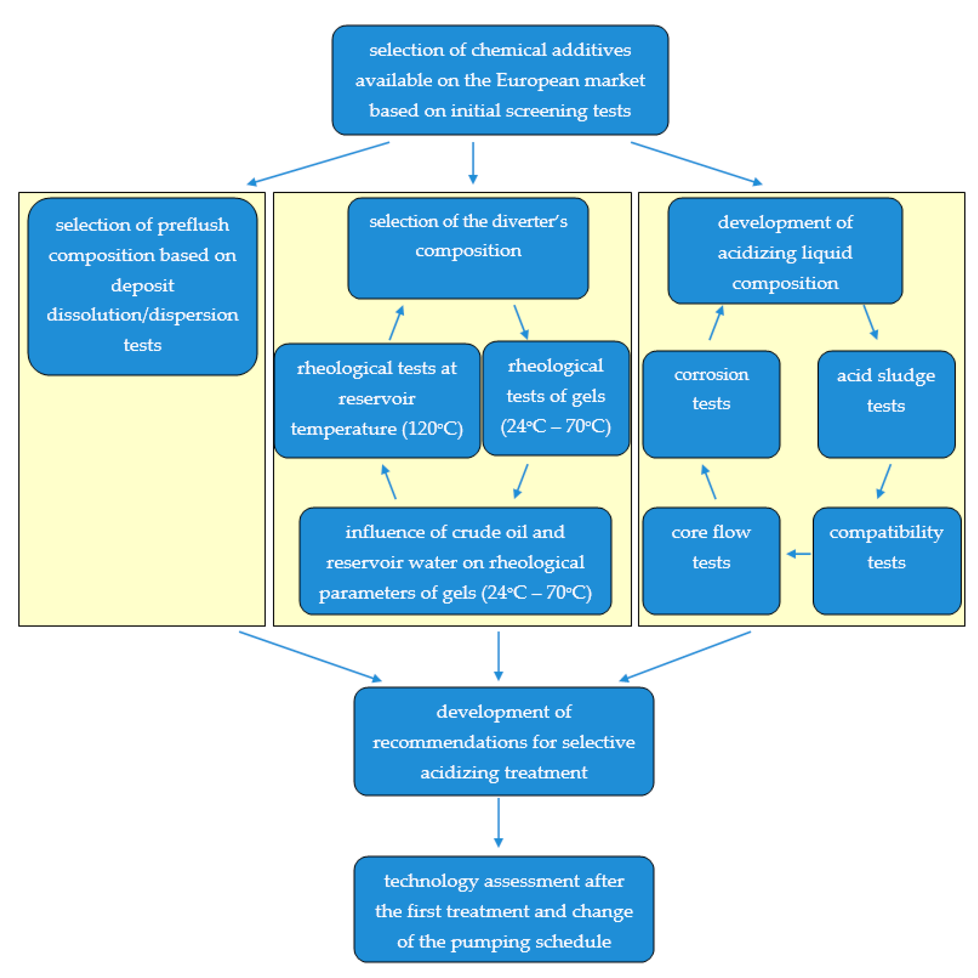
2. Materials and Methods
2.1. Materials and Chemical Additives
2.2. Methods
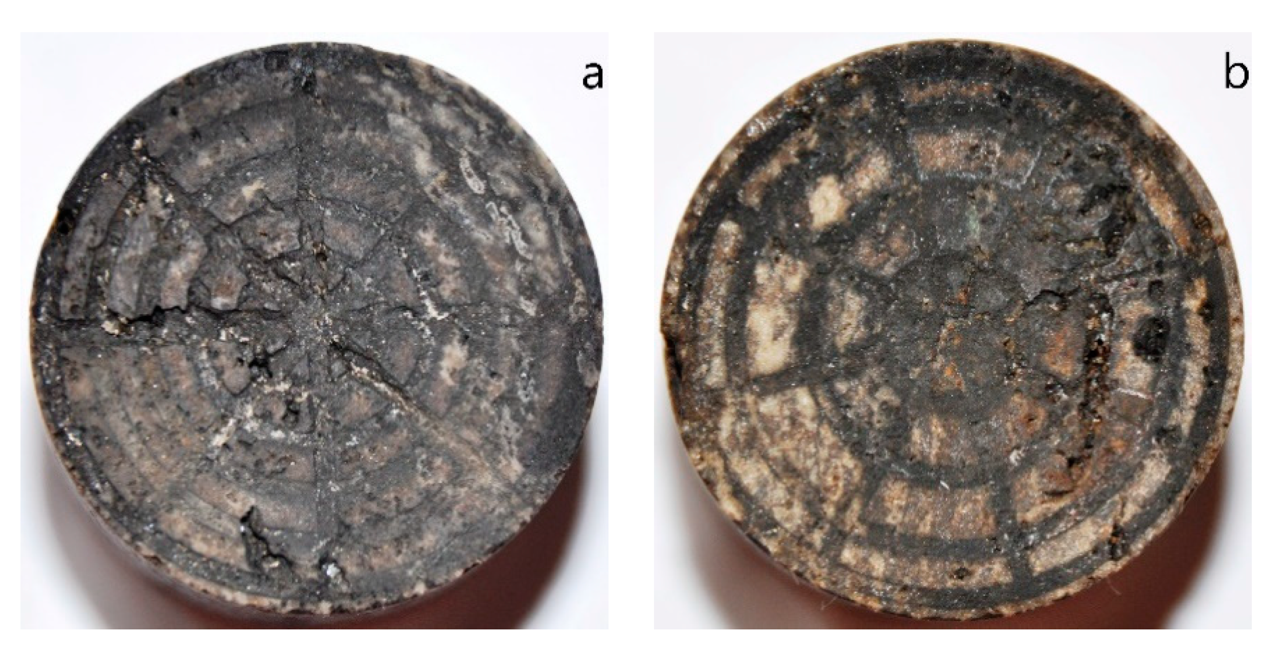
2.2.1. Organic Deposit Dissolution/Dispersion Tests
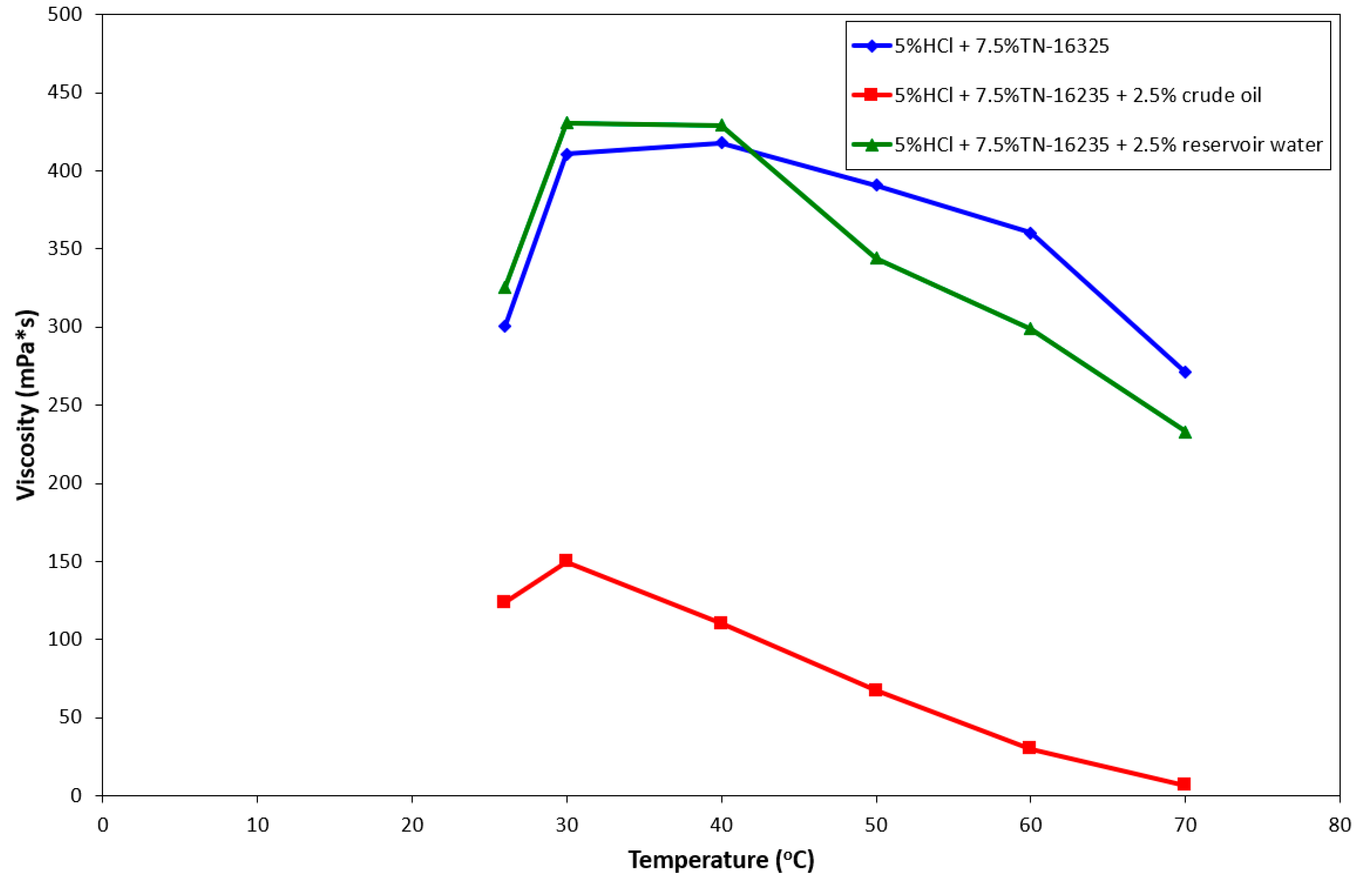
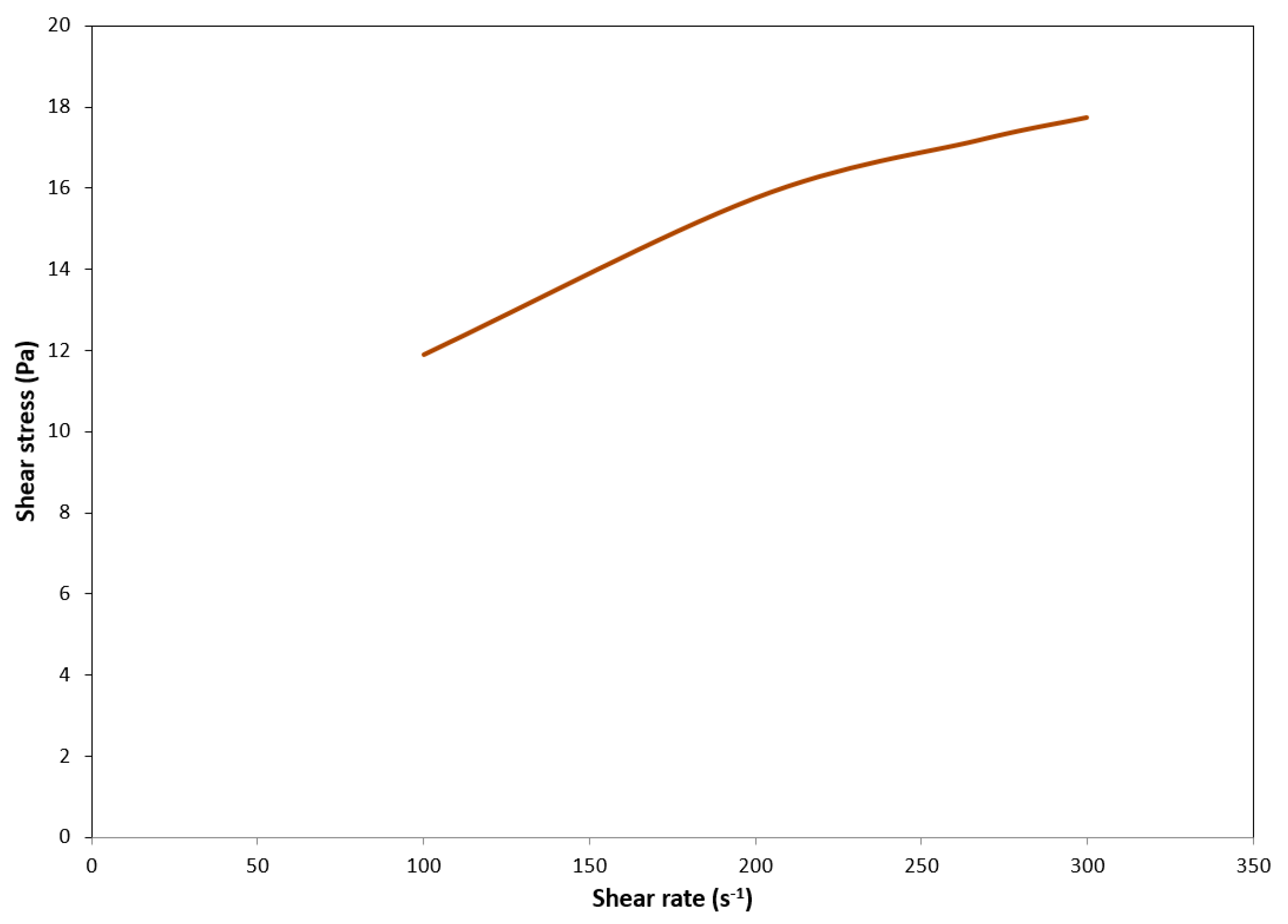
2.2.2. Rheological Tests
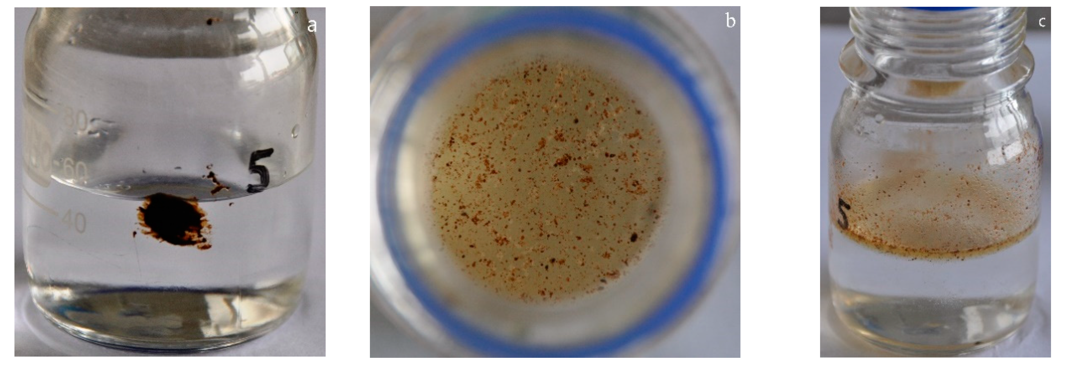
2.2.3. Acid Sludge Tests
2.2.4. Compatibility Tests
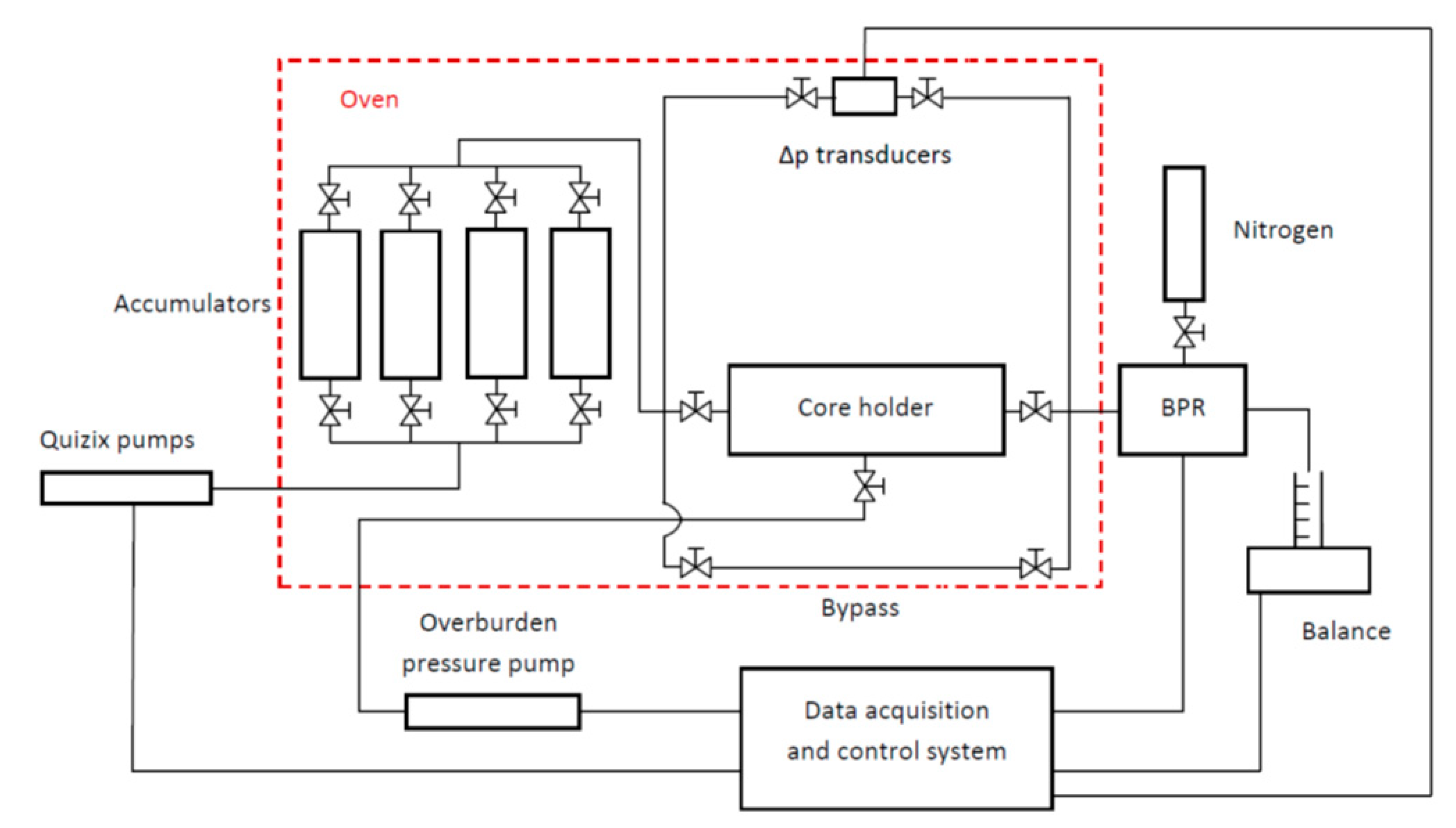
2.2.5. Core Flow Experiments
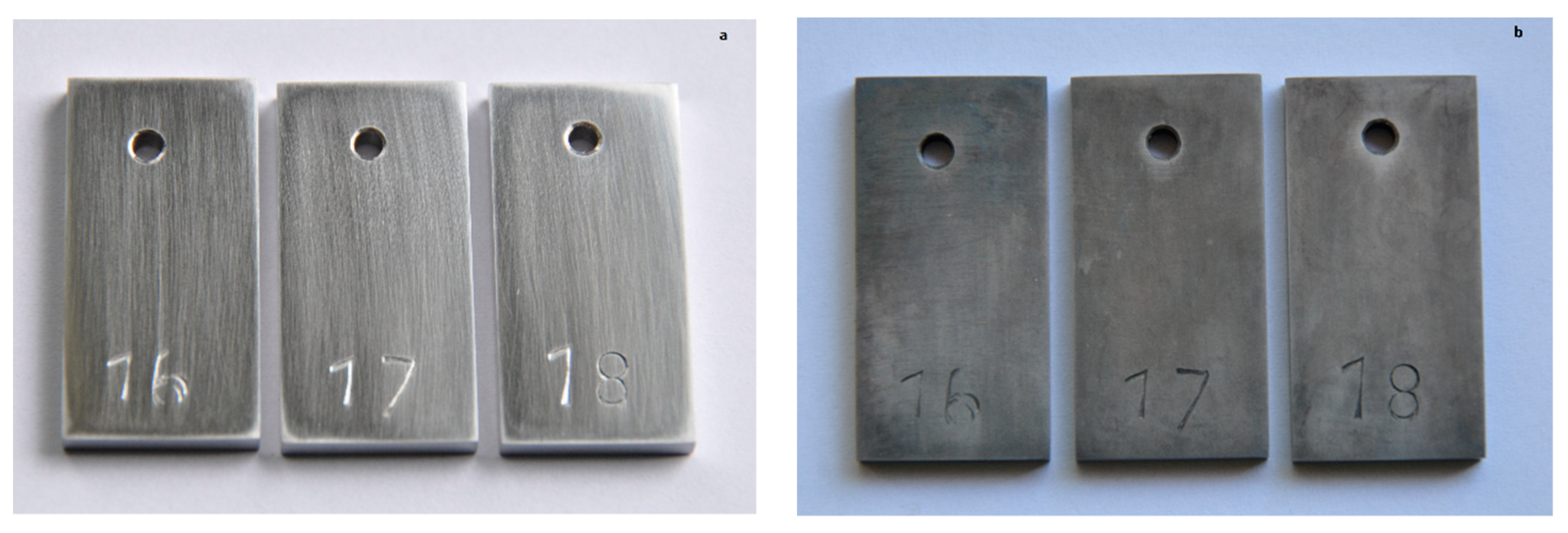
2.2.6. Corrosion Tests
3. Experimental Results
3.1. Selection of Preflush Composition
3.2. Selection of the Diverter’s Composition
3.3. Development of Acidizing Liquid Composition
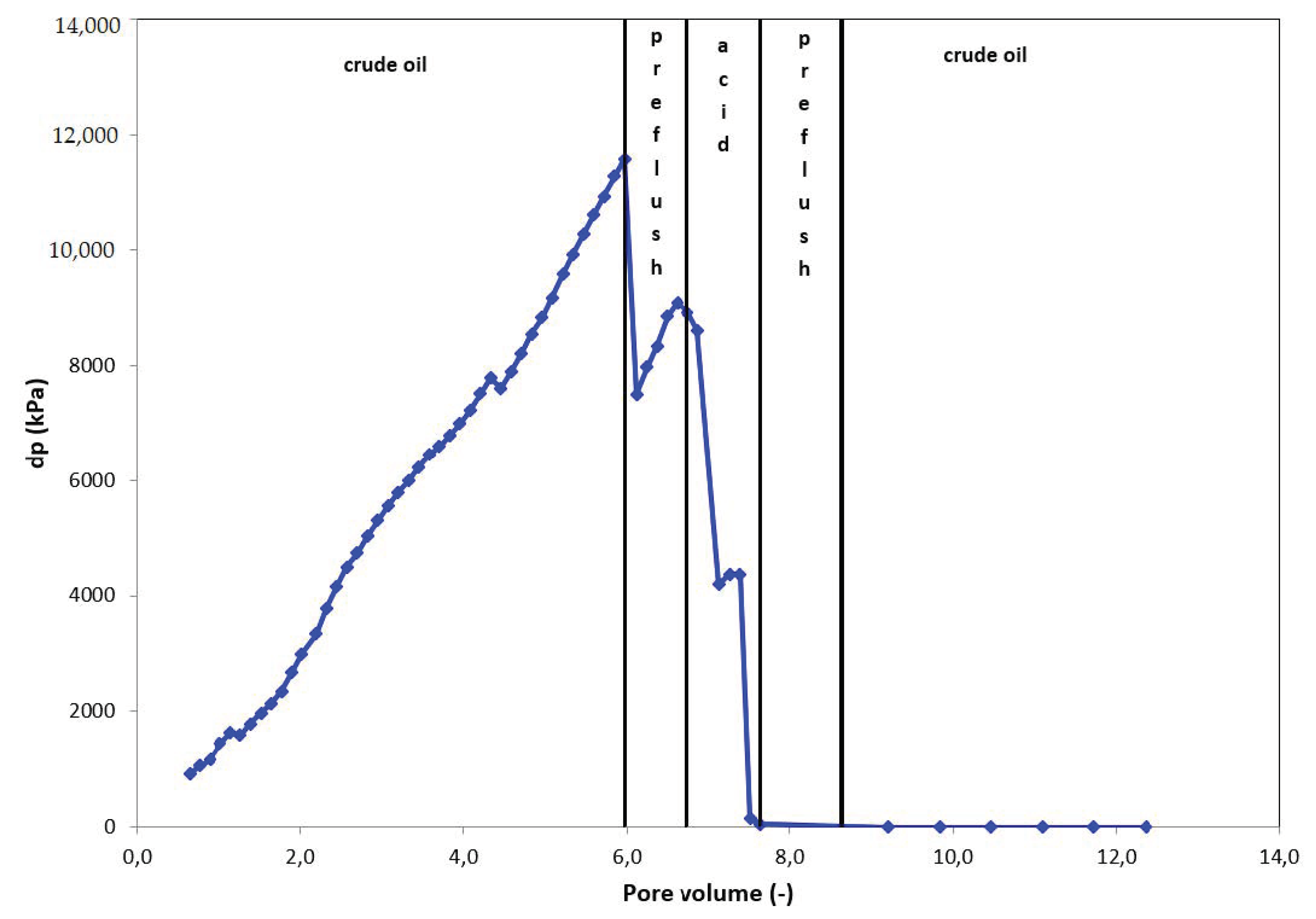
3.4. Results of Core Flow Experiments
4. Recommendations
5. Summary and Conclusions
Author Contributions
Funding
Acknowledgments
Conflicts of Interest
Nomenclature
| PV | Pore Volume |
| PVBT | Pore Volume to Breakthrough |
| SI | Stimulation Index |
References
- Allen, T.O.; Roberts, A.P. Production Operations; Oil & Gas Consultants International: Tulsa, OK, USA, 1993; Volume 2. [Google Scholar]
- Ott, W.K. Well Stimulation: Acidazing and Hydraulic Fracturing; IHRDC: Boston, MA, USA, 1991. [Google Scholar]
- Nasr-El-Din, H.A.; Al-Mohammad, A.M.; Al-Aamri, A.D.; Al-Fuwaires, O. Reaction of Gelled Acids with Calcite. SPE Prod. Oper. 2008, 353–361. [Google Scholar] [CrossRef]
- Fu, D.; Chang, F. Compositions and Methods for Treating a Subterranean Formation. WIPO Patent 2004/005671, 15 January 2004. [Google Scholar]
- Buijse, M.A.; de Boer, P.; Breukel, B.; Klos, M.; Burgos, G. Organic Acids in Carbonate Acidizing. In Proceedings of the SPE European Formation Damage Conference, Hague, The Netherlands, 13–14 May 2003. [Google Scholar] [CrossRef]
- van Domelen, M.S.; Jennings, A.R. Alternate Acid Blends for HPHT Applications. In Proceedings of the Offshore Europe, Aberdeen, UK, 5–8 September 1995. [Google Scholar] [CrossRef]
- Alkhaldi, M.H.; Nasr-El-Din, H.A.; Sarma, H. Kinetics of the Reaction of Citric Acid with Calcite. SPE J. 2010, 15, 704–713. [Google Scholar] [CrossRef]
- Fredd, C.N.; Fogler, H.S. Alternative Stimulation Fluids and their Impact on Carbonate Acidizing. SPE J. 1998, 3, 34–41. [Google Scholar] [CrossRef]
- Fredd, C.N.; Fogler, H.S. The Influence of Chelating Agents on the Kinetics of Calcite Dissolution. J. Colloid Interface Sci. 1998, 204, 187–197. [Google Scholar] [CrossRef] [PubMed]
- Rabie, A.I.; Mahmoud, M.A.; Nasr-El-Din, H.A. Reaction of GLDA with Calcite: Reaction Kinetics and Transport Study. In Proceedings of the SPE International Symposium on Oilfield Chemistry, The Woodlands, TX, USA, 11–13 April 2011. [Google Scholar] [CrossRef]
- Dill, W.R.; Keeney, B.R. Optimizing HCl-Formic Acid Mixtures for High Temperature Stimulation. In Proceedings of the SPE Annual Fall Technical Conference and Exhibition, Houston, TX, USA, 1–3 October 1978. [Google Scholar] [CrossRef]
- Katheeri, M.; Nasr-El-Din, H.A.; Taylor, K.C.; Grainees, A.H. Determination and Fate of Formic Acid in High Temperature Acid Stimulation Fluids. In Proceedings of the International Symposium and Exhibition on Formation Damage Control, Lafayette, LA, USA, 20–21 February 2002. [Google Scholar] [CrossRef]
- Taylor, K.C.; Al-Katheeri, M.I.; Nasr-El-Din, H.A. Development and Field Application of a New Measurement Technique for Organic Acid Additives in Stimulation Fluids. SPE J. 2005, 10, 152–160. [Google Scholar] [CrossRef]
- Buijse, M.A.; van Domelen, M.S. Novel Application of Elmulsified Acids to Matrix Stimulation of Heterogeneous Formations. In Proceedings of the SPE Formation Damage Control Conference, Lafayette, LA, USA, 18–19 February 1998. [Google Scholar] [CrossRef]
- Rabie, A.I.; Gomaa, A.M.; Nasr-El-Din, H.A. Determination of Reaction Rate of In-Situ Gelled Acids with Calcite Using the Rotating Disk Apparatus. In Proceedings of the SPE Production and Operations Conference and Exhibition, Tunis, Tunisia, 8–10 June 2010. [Google Scholar] [CrossRef]
- Nasr-El-Din, H.A.; Al-Mohammad, A.M.; Al-Aamri, A.D.; Al-Fahad, M.A. Quantitative Analysis of Reaction-Rate Retardation in Surfactant-Based Acids. SPE Prod. Oper. 2009, 24, 107–116. [Google Scholar] [CrossRef]
- Crowe, C.W.; Miller, B.D. New, Low-Viscosity Acid-In-Oil Emulsions Provide High Degree of Retardation at High Temperature. In Proceedings of the SPE Rocky Mountain Regional Meeting, Billings, MT, USA, 15–16 May 1974. [Google Scholar] [CrossRef]
- Sayed, M.A.; Nasr-El-Din, H.A. Reaction Rate of Emulsified Acids and Dolomite. In Proceedings of the SPE International Symposium and Exhibition on Formation Damage Control, Lafayette, LA, USA, 15–17 February 2012. [Google Scholar] [CrossRef]
- Sayed, M.A.; Nasr-El-Din, H.A.; Nasrabadi, H. Reaction of Emulsified Acids with Dolomite. J. Can. Pet. Technol. 2013, 52, 164–175. [Google Scholar] [CrossRef]
- Chang, F.F.; Nasr-El-Din, H.A.; Lindvig, T.; Qiu, X.W. Matrix Acidizing of Carbonate Reservoirs Using Organic Acids and Mixture of HCl and Organic Acid. In Proceedings of the SPE Annual Technical Conference and Exhibition, Denver, CO, USA, 21–24 September 2008. [Google Scholar] [CrossRef]
- Ortega, A.; Nasr-El-Din, H.A.; Rimassa, S. Acidizing High Temperature Carbonate Reservoirs Using Methanesulfonic Acid: A Coreflood Study. In Proceedings of the American Association of Drilling Engineers Fluids Technical Conference and Exhibition, Houston, TX, USA, 15–16 April 2014. [Google Scholar]
- Rabie, A.I. Reaction of Calcite and Dolomite with In-Situ Gelled Acids, Organic Acids, and Environmentally Friendly Chelating Agent (GLDA). Ph.D. Thesis, Texas A&M University, College Station, TX, USA, 2012. [Google Scholar]
- Chen, Y.; Mahdi, A.; Marcinew, R.; Graham, M.; Pope, T.L. Viscoelastic Surfactant Acid Treatment. U.S. Patent 8,895,481, 25 November 2014. [Google Scholar]
- Fu, D.; de Victoria, M.G.-L. Viscoelastic Acid. U.S. Patent 2005/0126786, 16 June 2005. [Google Scholar]
- Fu, D.; Panga, M.; Kefi, S.; de Victoria, M.G.-L. Self Diverting Matrix Acid. U.S. Patent 2006/0081370, 20 April 2006. [Google Scholar]
- Pandya, N.K.; Wadekar, S.D.; Pathre, G.S. Branched Viscoelastic Surfactant for High-Temperature Acidizing. U.S. Patent 2014/0246198, 4 September 2014. [Google Scholar]
- Plasier, R.C.; Allen, S.R. Surfactant Based Viscoelastic Fluids and Methods of Using the Same. U.S. Patent 8,196,662, 12 June 2012. [Google Scholar]
- Qu, Q.; Alleman, D. Acid Diverting System Containing Quaternary Amine. U.S. Patent 7,115,546, 3 October 2006. [Google Scholar]
- Wadekar, S.D.; Pandya, N.K.; Salgaonkar, L.P.; Sabhapondit, A. Cationic Visoelastic Surfactant with Non-Cationic Corrosion Inhibitor and Organic Anion for Acidizing. U.S. Patent 2014/0256604, 11 September 2014. [Google Scholar]
- Welton, T.D.; Lewis, S.J.; Funkhouser, G.P. Viscoelastic Surfactant Fluids and Associated Acidizing Methods. U.S. Patent 7,159,659, 9 January 2007. [Google Scholar]
- Kelland, M.A. Production Chemicals for the Oil and Gas Industry, 2nd ed.; CRC Press: Boca Raton, FL, USA, 2014. [Google Scholar]
- Chang, F.F.; Love, T.; Affeld, C.J.; Blevins, J.B., III; Thomas, R.L.; Fu, D.K. Case Study of a Novel Acid-Diversion Technique in Carbonate Reservoirs. In Proceedings of the SPE Annual Technical Conference and Exhibition, Houston, TX, USA, 3–6 October 1999. [Google Scholar] [CrossRef]
- Holt, S.; Zhou, J.; Gadberry, F.; Nasr-El-Din, H.; Wang, G. A Novel Viscoelastic Surfactant Suitable for Use in High Temperature Carbonate Reservoirs for Diverted Acidizing Stimulation Treatments. In Proceedings of the Rio Oil & Gas Expo and Conference 2012, Rio de Janeiro, Brazil, 17–20 September 2012. [Google Scholar]
- Kasza, P.; Dziadkiewicz, M.; Czupski, M. From Laboratory Research to Successful Practice: A Case Study of Carbonate Formation Emulsified Acid Treatments. In Proceedings of the SPE International Symposium and Exhibition on Formation Damage Control, Lafayette, LA, USA, 15–17 February 2006. [Google Scholar] [CrossRef]
- API, R.P. Recommended Practices for Laboratory Evaluation of Surface Active Agents for Well Stimulation. In API RP 42, 2nd ed.; American Petroleum Institute (API): Washington, DC, USA, 1977. [Google Scholar]
- ASTM G1-03(2017)e1. Standard Practice for Preparing, Cleaning, and Evaluating Corrosion Test Specimens; ASTM International: West Conshohocken, PA, USA, 2017. [Google Scholar] [CrossRef]
- Smith, C.F.; Dollarhide, F.E.; Byth, N.J. Acid Corrosion Inhibitors—Are We Getting What We Need? J. Pet. Technol. 1978, 30, 737–746. [Google Scholar] [CrossRef]


| Average reservoir temperature: | 120 °C |
| Average permeability: | 9–28 mD |
| Pressure: | 38 MPa |
| Reservoir rock: | Dolomite (26–82%) Sulfates (10–20%) Anhydrite (10–30%) |
| Reservoir type: | Pore, fissure |
| Density (g/cm3) | Viscosity (mPa⋅s) | Asphaltenes (%) | Resins (%) | Saturated Hydrocarbons (%) | Aromatic Hydrocarbons (%) |
|---|---|---|---|---|---|
| 0.822 | 33.0 | 0.23 | 4.88 | 39.60 | 5.53 |
| Density (at 22 °C) (g/cm3): | 1.214 |
| pH: | 5.89 |
| Sodium concentration (mg/l): | 107,001 |
| Potassium concentration (mg/l): | 6267 |
| Calcium concentration (mg/l): | 34,003 |
| Magnesium concentration (mg/l): | 2429 |
| Chloride concentration (mg/l): | 239,453 |
| Bromide concentration (mg/l): | 2128 |
| Sulfates concentration (mg/l): | 220 |
| Bicarbonates concentration (mg/l): | 275 |
| 30% CaCl2 Solution + 4.5% TN-16235 | 30% CaCl2 Solution + 4.5% TN-16235 + 2.5% Reservoir Water | 30% CaCl2 Solution + 4.5% TN-16235 + 2.5% Crude Oil | |||||
|---|---|---|---|---|---|---|---|
| Time (min) | Temperature (°C) | n (-) | k (lbf·sn’/ft2) | n (-) | k (lbf·sn’/ft2) | n (-) | k (lbf·sn’/ft2) |
| 2.5 | 24 | - | - | - | - | - | - |
| 6.5 | 79 | 1.4134 | 0.0001 | 1.3612 | 0.0002 | 1.3723 | 0.0002 |
| 21.5 | 116 | 0.3320 | 0.0600 | 0.3557 | 0.0467 | 0.2343 | 0.0546 |
| 36.5 | 119 | 0.3251 | 0.0581 | 0.3868 | 0.0384 | 0.9085 | 0.0007 |
| 51.5 | 120 | 0.3618 | 0.0476 | 0.3873 | 0.0385 | 1.2122 | 0.0001 |
| 66.5 | 120 | 0.3800 | 0.0428 | 0.3683 | 0.0429 | 1.2986 | 0,00003 |
| 81.5 | 120 | 0.3688 | 0.0451 | 0.3818 | 0.0399 | 1.4686 | 0.00001 |
| 96.5 | 120 | 0.3708 | 0.0442 | 0.3687 | 0.0428 | - | - |
| 111.5 | 120 | 0.3690 | 0.0444 | 0.3697 | 0.0426 | - | - |
| 126.5 | 120 | 0,3983 | 0,0377 | 0.3589 | 0.0453 | - | - |
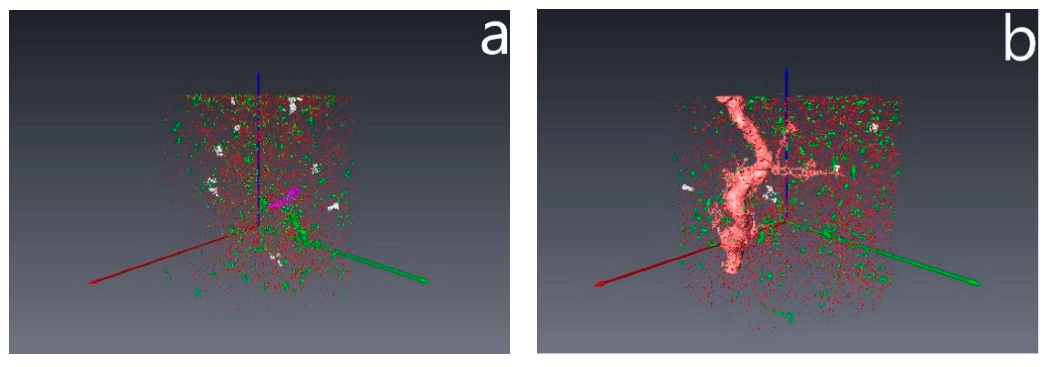
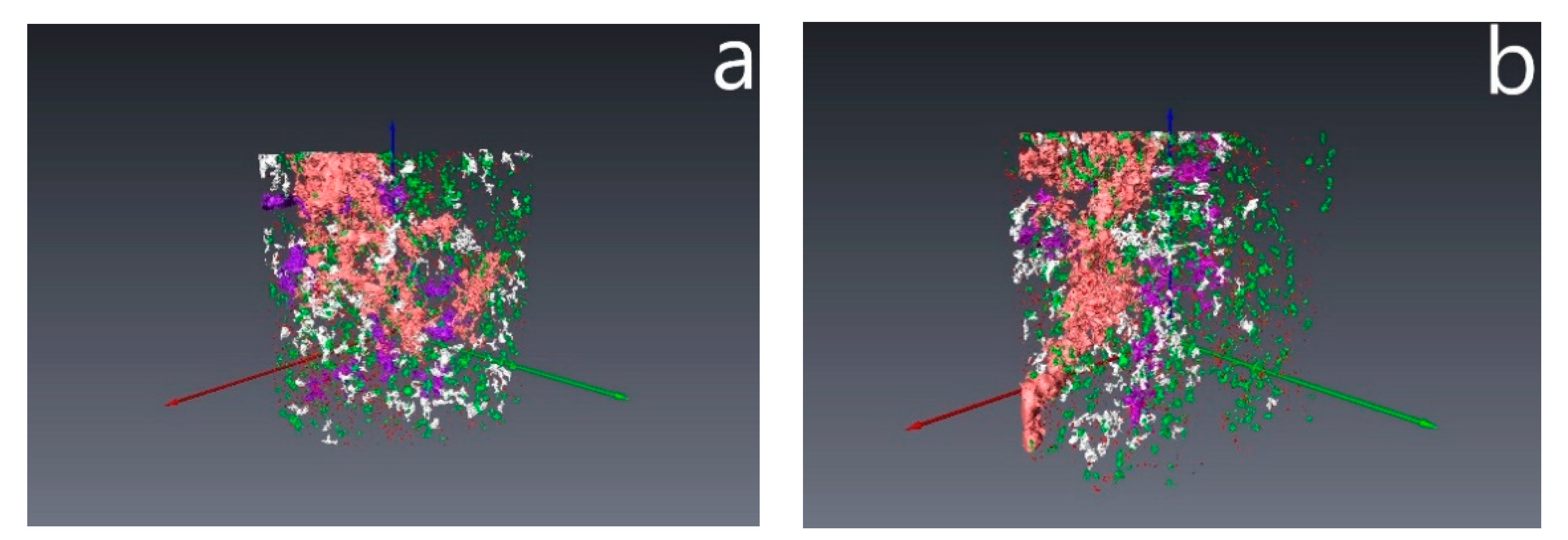
| Volume Class (-) | Volume (Voxel) | Volume (μm3) | Color (-) |
|---|---|---|---|
| I | 1–9 | 2.7 × 10⁴–2.7 × 10⁵ | |
| II | 10–99 | 2.7 × 10⁵–2.7 × 10⁶ | |
| III | 100–999 | 2.7 × 10⁶–2.7 × 10⁷ | |
| IV | 1000–9999 | 2.7 × 10⁷–2.7 × 10⁸ | |
| V | 10,000–99,999 | 2.7 × 10⁸–2.7 × 10⁹ | |
| VI | 100,000–400,000 | 2.7 × 10⁹–1.08 × 10¹⁰ | |
| VII | >400,000 | >1.08 × 10¹⁰ |
| Nitrogen Permeability before Acidization (mD) | Nitrogen Permeability after Acidization (mD) | Stimulation Index (Permeability after/Permeability before Acidizing) (-) | PVBT (-) |
|---|---|---|---|
| 3.0 | 190.7 | 63.6 | 0.65 |
| 39.2 | 604.0 | 15.4 | 0.72 |
Publisher’s Note: MDPI stays neutral with regard to jurisdictional claims in published maps and institutional affiliations. |
© 2020 by the authors. Licensee MDPI, Basel, Switzerland. This article is an open access article distributed under the terms and conditions of the Creative Commons Attribution (CC BY) license (http://creativecommons.org/licenses/by/4.0/).
Share and Cite
Czupski, M.; Kasza, P.; Leśniak, Ł. Development of Selective Acidizing Technology for an Oil Field in the Zechstein Main Dolomite. Energies 2020, 13, 5940. https://doi.org/10.3390/en13225940
Czupski M, Kasza P, Leśniak Ł. Development of Selective Acidizing Technology for an Oil Field in the Zechstein Main Dolomite. Energies. 2020; 13(22):5940. https://doi.org/10.3390/en13225940
Chicago/Turabian StyleCzupski, Marek, Piotr Kasza, and Łukasz Leśniak. 2020. "Development of Selective Acidizing Technology for an Oil Field in the Zechstein Main Dolomite" Energies 13, no. 22: 5940. https://doi.org/10.3390/en13225940
APA StyleCzupski, M., Kasza, P., & Leśniak, Ł. (2020). Development of Selective Acidizing Technology for an Oil Field in the Zechstein Main Dolomite. Energies, 13(22), 5940. https://doi.org/10.3390/en13225940