Article

Development of a Beta-Type Moderate-Temperature-Differential Stirling Engine Based on Computational and Experimental Methods

by
Chin-Hsiang Cheng
* and
Jhen-Syuan Huang
Department of Aeronautics and Astronautics, National Cheng Kung University, Tainan 70101, Taiwan
*
Author to whom correspondence should be addressed.
Energies 2020, 13(22), 6029; https://doi.org/10.3390/en13226029
Submission received: 30 October 2020 / Revised: 13 November 2020 / Accepted: 16 November 2020 / Published: 18 November 2020
(This article belongs to the Section I: Energy Fundamentals and Conversion)

Abstract

:
Stirling engine is a favorable technique in the application of waste heat recovery or cogeneration system. This paper aims at developing a beta-type Stirling engine which is operated at moderate heating temperature (773–973 K). Rhombic drive mechanism is utilized to make coaxial motion of displacer and piston. Based on the proposed dimensions, a theoretical model combining thermodynamic and dynamic analysis is built to predict the performance of the Stirling engine. Thermodynamic analysis deals with variations of properties in each chamber while dynamic analysis handles the resultant shaft torque produced by the Stirling engine. Furthermore, a prototype engine is manufactured, and experimental test is carried out to validate the simulated results in this research. Under heating temperature of 973 K, charged pressure of 8 bar, rotation speed of 1944 rpm, shaft power of 68 W is obtained from the prototype Stirling engine. Power density is calculated to be 1.889 W-c.c.−1 by theoretical prediction and 1.725 W-c.c.−1 by tested result. The impact of the geometrical dimensions is investigated to survey the optimal piston diameter which is related to compression ratio and swept volume.

Graphical Abstract

1. Introduction

As an external heat engine, the Stirling engine features availability to most heat sources, such as solar, biomass, geothermal, nuclear, and waste heat energy. In recent years, capacity and efficiency of Stirling engines have been remarkably lifted and lots of effort were paid to implement the practical utilization of this technology [1]. Atmosphere gas like air, nitrogen, helium, and hydrogen can be adopted as working medium in Stirling engines [2,3]. Three main kinds of structure are exploited in Stirling engines, which are alpha-, beta-, and gamma-type. According to first-order analysis on design parameters, beta-type Stirling engine has the highest dimensionless work output [4]. Coaxial movement of piston and displacer is the characteristic of beta-type Stirling engine, which results in a more compact configuration and better power density. Cinar et al. [5] designed an air-charged beta-type Stirling engine with crank mechanism. At hot-source temperature of 1000 °C generated from a radioactive heater, the test engine can generate 5.98 W at 208 rpm. Aksoy et al. [6] adopted a slotted lever to implement the displacement of displacer and piston. The engine was tested with halogen lamp and power of 127.17 W was achieved at heating temperature of 873 K. In contrast to crank mechanism, Meijer [7] demonstrated a rhombic drive mechanism firstly which successfully operated to achieve the scale of 3 W–8.95 kW. The advantage of rhombic drive mechanism is that piston and displacer bear less lateral force due to the symmetrical geometry, and hence vibration and noise are remarkably reduced. Erol and Caliskan [8] compared performance of four mechanisms of beta-type Stirling engines with isothermal and kinematic analysis. At the same swept volume of 365 cm3 and charged mass of 7.16 × 10⁻⁴ kg, net output works obtained by bell crank, slide crank, rhombic, and scotch yoke drive mechanisms are 12.85, 12.09, 15.49, and 12.91 J, respectively. Rhombic drive mechanism performed roughly 20 % better than others. Hirata et al. [9] designed a beta-type Stirling engine whose swept volume is 81.4 c.c. and the output power obtained was 60 W with nitrogen being the working gas. Ni et al. [10] demonstrated a beta-type Stirling engine with rhombic drive mechanism operated at 16–30 bar pressure. The maximum powers for the working gas of helium and nitrogen are 69.44 and 36.78 W, respectively.
One of the attractive applications of the Stirling engine is waste heat recovery [11,12,13]. Since Stirling engines can be integrated with different forms of thermal energy without contaminating their working fluid, it is possible to harvest waste heat and generate power. Durcansky, Nosek, and Jandacka [14] evaluated the possibility of utilizing waste energy between 300 and 800 °C. A commercial Cleanergy Stirling engine operated between 15 and 90 bar was shown to obtain 400–4900 W. Aladayleh and Alahmer [15] studied the potentiality of recycling the waste heat of an automobile combustion engine with Stirling engine. Exhaust temperature of a combustion engine may reach 200–700 °C, which is in moderate level for Stirling engines. Wang et al. [16] reviewed Stirling engines that are operated at moderate temperature differences ranging from 0.5 to 375 °C. Power density of Stirling engine under moderate temperature locates between 0.005 and 2 W-c.c.−1 [17]. Kropiwnicki and Furmanek [18] developed an alpha-type Stirling engine prototype which is driven by the waste gases of a combustion engine. The designed swept volume is 730 c.c. and the working gas is air. The 114 W power is achieved at temperature of 350 °C and pressure of 6 bar. With optimization on the heater and cooler size, engine power was elevated to 369 W. Combination of nonideal adiabatic model and simplified conjugate-gradient method was used to optimize a four-cylinder double-acting Stirling engine by Cheng and Tan [19]. The approach was validated with robustness and the indicated power can be improved by 56%. Three-dimensional simulation based on CFD software has been used to investigate the distribution of temperature and pressure inside a beta-type Stirling engine [20,21]. Compared to high-temperature Stirling engines, moderate-temperature ones produce lower power and efficiency. Nevertheless, the moderate-temperature-differential Stirling engines feature higher reliability and smaller volume.
The aim of the present study is to develop a beta-type Stirling engine with rhombic drive mechanism that is operated at moderate heating temperature. In order to predict engine performance, a theoretical model that deals with the thermodynamic and dynamic process is established. Moreover, a prototype Stirling engine based on the analyzed dimensions is designed and manufactured. Experimental apparatus for measuring engine performance is constructed and running tests are carried out for model validation. Effects of charged pressure and heating temperature are investigated by means of numerical simulation and experimental measurement in parallel. Parametric study on clearance length and bore size of compression chamber is also conducted to find out the optimal design parameters.

2. Theoretical Model

In beta-type Stirling engine, a displacer and a power piston are used to generate volume variations in expansion and compression chamber with a certain phase angle. Expansion and compression chamber are set at high and low temperature regions, respectively, and working gas will shuttle between these two chambers. Figure 1 shows the schematic of studied beta-type Stirling engine where three heat exchangers are also incorporated. A heater and cooler are introduced to enhance the heat transfer in hot and cold ends. They are composed of numerous tubes and immersed in the heat sinks. Between the heater and cooler, regenerator is an internal heat exchanger that serves as thermal inertia and provides a great amount of heat transfer area. The regenerator is usually composed of porous material and benefits maintaining the axial temperature gradient. While high temperature working gas passes through the regenerator, its internal energy will be preserved inside the material. The energy is afterward recycled as working gas returns from the compression chamber. Stainless steel (SS304) mesh that is composed of crossed metal wire is employed as regenerator for the present Stirling engine. Below power piston, the back chamber functions as a buffer for the working zone and it is taken isolated in the present model. Rhombic drive mechanism is adopted to drive a pair of gears where the right gear serves as the main rotor to endure shaft load. In the figure, y p and y d are displacements of the piston and displacer while θ is the crank angle about the main shaft. D d , D p , and D b are the diameters of displacer, piston, and back chamber rod, respectively. L c e and L c c are clearance lengths of expansion and compression chamber.
In this paper, a theoretical model is used to simulate the transient process via thermodynamic analysis for working gas and dynamic analysis for mechanical components. As indicated on the schematic, the working zone consists of expansion, heater, regenerator, cooler, and compression chambers. In thermodynamic analysis, properties including volume, mass, pressure, and temperature in each chamber are calculated by ideal-gas, continuity, momentum, and energy equations. Volume variations of expansion and compression chamber are calculated once the displacements of piston and displacer are updated with crank angle. After that, average pressure inside engine p a v e is obtained and mass in each chamber can be evaluated as
m i = p a v e V i / R c o n s t T i ,   i =   e ,   h ,   r ,   k ,   c
In the above equation, mi, Vi, and Ti are mass, volume, and temperature in each chamber. Rconst is gas constant whose value is 2077 J-kg−1-K−1 in the present case that helium is used. Subscripts e, h, r, k, c stand for expansion, heater, regenerator, cooler, and compression chamber.
Mass flow rate across the boundaries can be evaluated by continuity equation. As working gas flows through heater, regenerator, and cooler, it suffers from viscous friction on the channel surface. Therefore, pressure drops in these three elements should be considered. Friction factors f regarding Reynolds number can be described as [22]
f i = 64 / Re i ,   i =   h ,   k
f i = 129 / Re i + 2.91 Re i 0.103 ,   i =   r
where Reynolds number is determined in terms of the hydraulic diameter. As a result, pressure drop across three heat exchangers can be estimated with the help of Darcy–Weisbach equation. In present model, average pressure is set at the regenerator, and the pressures in other chambers are determined as
p e = p h + Δ p h / 2
p h = p r + ( Δ p h + Δ p r ) / 2
p r = p a v e
p k = p r ( Δ p r + Δ p k ) / 2
p c = p k Δ p k / 2
where Δ p h , Δ p r , and Δ p k are pressure of heater, regenerator, and cooler chamber, respectively.
For the back chamber, it is assumed that there is no mass leakage in the chamber and its temperature remains constant. Thus, the pressure in the back chamber ( p b ) can be evaluated with ideal-gas equation as
p b V b = constant
where back chamber volume Vb is related to the position of piston.
In order to determine temperature variation of the working gas, the energy equation of each chamber is used. That is
d ( m i c v T i ) d t = Q ˙ i W ˙ i + m ˙ i n , i   c p T i n , i m ˙ o u t , i   c p T o u t , i   ,   i =   e ,   h ,   r ,   k ,   c
In the above equation, Q ˙ is the heat transfer input and W ˙ is the work output. Work output is evaluated by the boundary work in the expansion and compression chambers. Since volumes of heater, regenerator, and cooler chamber remain unchanged, no boundary work is exerted. m ˙ i n and m ˙ o u t are mass flow rate into and out of the chamber. Tin and Tout are inlet and outlet temperatures.
Heat transfer input depends on thermal resistance between the working gas and the heat sink. For the working gas flowing in the channel of heater, regenerator, and cooler, convection heat transfer dominates. The convective heat transfer coefficient can be determined from Nusselt number [23] as
Nu i = 3.66 ,   i =   h ,   k
Nu i = 0.33 Re i 0.67 ,   i =   r
In thermodynamic analysis, volume, mass, pressure, and temperature are calculated. Subsequently, pressure of working zone is brought into dynamic analysis for predicting the resultant shaft torque of the engine. Yang, et al. [24] presented the dynamic relations of rhombic drive mechanism for a 1-kW Stirling engine, in which friction of each joint is considered. The friction caused by the ball bearing is relatively small compared to the dry friction at the piston–cylinder interface and the resistance of the shaft seal. Besides, gravitational and inertial energies of components are demonstrated to be trivial compared to the driving power as well. Cheng et al. [25] conducted experimental measurements for the mechanical loss of rhombic drive mechanism. It is found that the overall friction power can be represented in polynomial form as a function of the rotation speed. In this study, the analysis in [24] is simplified by neglecting the effects of joint friction, gravitational, and inertial energies. All the frictions involved in the engine are summarized in terms of angular speed. The angular acceleration α of the main shaft can be evaluated in the following equation once the pressures in the expansion, compression, and back chambers are determined.
α = ( W ˙ d r i W ˙ f r i W ˙ s h ) / ω I f
where
W ˙ d r i = ( p c p b ) [ ( A p A b ) v p + A b v d ] ( p e p c ) A d v d
W ˙ f r i = c 1 ω + c 2 ω 2
W ˙ s h = τ s h   ω
In the above equations, W ˙ d r i is the driving power induced by the gas pressures of expansion, compression, and back chambers; W ˙ f r i is the frictional power represented in a second-order polynomial form; W ˙ s h is the shaft power defined by the product of exerted shaft torque τ s h   and angular speed   ω . v p and v d are linear velocities of the piston and displacer. In addition, c1 and c2 are two coefficients determined according to the experimental data. For the present case, c1 = 2.025 × 10⁻¹ W-s, and c2 = 1.125 × 10⁻⁴ W-s2.
Figure 2 shows the flow chart of the computation with the proposed theoretical model. An initial rotation speed is applied and after a starting period the engine is able to reach the steady operation state. At each time step, thermodynamic and dynamic analyses are performed simultaneously and iteratively until the properties, m, p, T, and α converge to the solutions. Table 1 lists the design parameters of the studied Stirling engine.

3. Prototype Engine and Experimental Setup

In this paper, a prototype beta-type Stirling engine based on the above-mentioned parameters was manufactured to validate the raised model. Figure 3a shows the picture of the designed Stirling engine prototype. Components of the Stirling engine require high precision machining and accurate assembly. The piston and cylinder were made with fine surface roughness and matched in tight tolerance. Hermetic seals were applied at the junctions of parts to avoid gas leakage. Copper pipe was used as the heat exchanger in the heating zone for its good thermal conductivity.
For the purpose of acquiring performance of the designed Stirling engine, a setup of experimental apparatus shown in Figure 3b was constructed. Kuehl [26] put forward empirical equations for estimating the transport properties of gases. Dynamic viscosity and thermal conductivity of the available working gases in Stirling engine are listed in Table 2, where the values were calculated based on the equations in [26] and the conditions were set at 873 K and 6 bar based on Table 1. It can be found that dynamic viscosity of hydrogen is roughly half of air, nitrogen, and helium. In terms of thermal conductivity, helium and hydrogen perform 6–13 times better than air and nitrogen. Despite the fact that conductivity of helium is 44 % of hydrogen, helium was chosen as the working gas due to its availability and safety. Interior air should be drawn out firstly by vacuum pump and high purity (99.999%) helium is then filled into the engine. Charged pressure was controlled by a pressure regulator whose operational range is 0–10 bar and resolution is 0.01 bar. In experiments, an electric heater was used to supply thermal energy for the engine, and the heating temperature was adjusted with a PID controller. The engine shaft was connected to a torque and speed sensor and a hysteresis brake. In this manner, the shaft power can be determined in terms of the torque and rotation speed measured. Variation of heating temperature, engine torque, and rotation speed were collected and recorded by a data acquisition system.
The major parameters measured in the experiment were charged pressure, heating temperature, shaft torque, and rotation speed. Uncertainty analysis proposed by Moffat [27] is performed in Table 3 where the parameters are estimated with 95% confidence. Relative uncertainty of shaft power is calculated to be 3.7%.

4. Results and Discussion

In the computation, once the steady operation was reached, an increment of shaft torque was added. The shaft torque was increased to alter the rotation speed as well as the shaft power. Figure 4 displays the dynamic simulation by plotting the variations in the average rotation speed and the shaft power in response to shaft torque change. The charged pressure is 4 bar and the heating temperature is 723 K. As shown in Figure 4a, the Stirling engine is accelerated from the initial condition without shaft torque and it takes about 64 s to attain the steady operation regime. While the resisting shaft torque is applied, engine speed will be gradually declined to another level. The variation in the shaft power is plotted in Figure 4b. In this figure, data of the friction power, driving power, and net heat input are also provided. The net heat input of the Stirling engine, Q ˙ n e t , is the sum of heat transfer rates in all chambers. It is clearly observed that larger heat input is required into the engine in the first few seconds. At each steady level, net heat input rate is balanced by the driving power. Note that the driving power is consumed by the friction power and the shaft power in the steady operation regime with α = 0, as indicated in Equation (13).
Performance curves of the designed Stirling engine under different charged pressures and heating temperatures are illustrated in Figure 5, where both numerical and experimental results are provided. For the present engine the heating temperature varied from 500 to 700 °C (i.e., 773–973 K). Thus, the difference between heating and cooling temperatures ranges within 473–673 K. For 4-bar charged pressure shown in Figure 5a, the engine can be actuated at heating temperature of 773 K and peak shaft power of the prototype is 16 W at 1108 rpm. As the heating temperature is increased to 973 K, shaft power is lifted to 47 W in numerical simulation and 44 W in measurement. For 6-bar charged pressure, the operated heating temperature is between 823 and 973 K as displayed in Figure 5b. Shaft power ranges from 36 to 64 W in theoretical model and from 29 to 60 W in experimental data. In case of 8-bar charged pressure, the lowest heating temperature for starting engine is observed to be 873 K in testing. It can be found that the lowest heating temperature depends on the charged pressure of the designed engine. Since more working gas is filled in the engine at larger charged pressure, higher heating temperature is required to supply sufficient heat energy to actuate the engine. At 8-bar charged pressure and 973-K heating temperature, shaft power is predicted to be 74 W in simulation and verified to be 68 W in experiment.
Clearance length is defined to describe the least distance that causes dead volume for a chamber. In the present design of beta-type Stirling engine, clearance lengths of expansion and compression chambers are 0.003 and 0.0165 m, respectively. If the dead volume of the compression chamber can be reduced, the compression ratio is increased and engine performance can be improved due to the more efficient compression of working gas. Figure 6 shows the effects of the clearance length and piston diameter on the engine performance under 8-bar charged pressure and 973-K heating temperature. In Figure 6a, clearance length of the compression chamber is decreased from 0.0165 to 0.0005 m, which makes an increase of compression ratio from 1.242 to 1.300. As a result, shaft power is raised from 74 to 82 W, indicating 11 % enhancement.
Influence of the piston diameter is displayed in Figure 6b. Compression ratio will be elevated to 1.463 while the diameter is increased to 0.07 m. It is noted that performance curve is narrowed, and the maximum rotation speed is lowered as the diameter gets larger. Stirling engine is accelerated by the driving torque which comes from the normal pressure force on the piston. However, pressure of back chamber which also exerts on the cross area of the piston will balance the resultant force on the piston. As the cross section is larger, the force induced by the back chamber is increased under the same charged pressure, which drops the maximum speed of the engine. It can be seen that shaft power is lifted to 85 W in the case of 0.06 m piston diameter, where 15 % power improvement is obtained. For 0.065 m piston diameter, shaft power will slightly decrease with a lower speed. When the piston diameter is 0.07 m, shaft power declines to 80 W.
Figure 7 shows the effect of piston diameter on the compression ratio and power density under 8-bar charged pressure and 973-K heating temperature. Compression ratio is increased with larger piston diameter, as plotted in the figure. Power density is defined as the ratio of peak shaft power and swept volume of the piston. In the proposed Stirling engine, power density is predicted to be 1.889 W-c.c.−1 and tested to be 1.725 W-c.c.−1. On the other hand, it is noticed from the figure that an optimal value of power density exists. Highest power density is 2.020 W-c.c.−1 in the case of 0.042 m piston diameter. It can be deduced that piston diameter of 0.06 m leads to the largest shaft power and piston diameter of 0.042 m yields the best power density. For the purpose of more comprehensive analysis of the Stirling engine, design parameters including piston stroke, displacer diameter, displacer stroke, and phase angle should be studied simultaneously and optimized through optimization method.
A comparison of developed beta-type Stirling is shown in Table 4. It is noted that the present Stirling engine yields higher power density than those presented in [6] and [9] at nearly equal pressure and temperature. In comparison to a high-pressure system (29.6 bar) demonstrated in [10], the present engine is lower only by 0.075 W-c.c.−1.
Note that the present study aimed to develop a moderate-temperature-differential Stirling engine. From design point of view, the β-type Stirling engines are well suitable for development of the compact engines. Therefore, both modeling and prototyping phases were combined in this study so as to fulfill the aim. The compact property of the engine is a criterion to be competitive in personal power generation applications.

5. Conclusions

In this study, a beta-type Stirling engine for heating temperature from 773 to 973 K was developed. Dynamic and thermodynamic analyses were built to simulate the characteristic of the engine behavior. A prototype Stirling engine was manufactured, and experiments of different charged pressure and heating temperature were performed. Conclusions obtained from this research are listed as below.
(1)
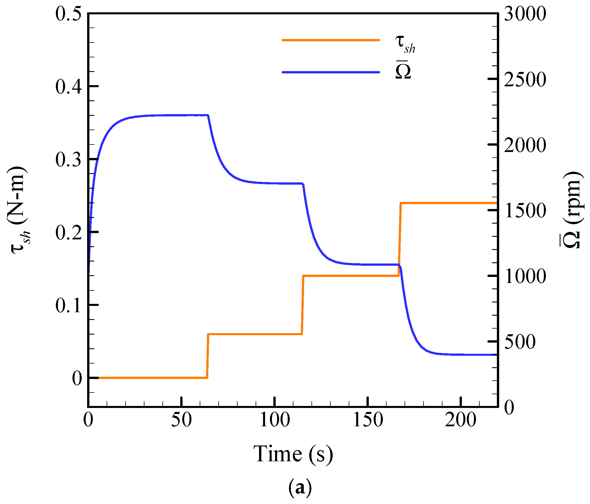
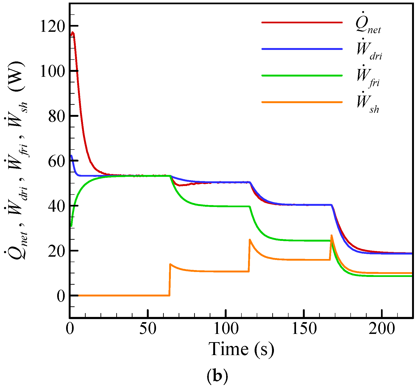
Dynamic behavior of the Stirling engine in response to varied shaft torque was demonstrated in the paper. Time-dependent variations of rotation speed and energies were illustrated. Conservation of energy was also satisfied to certify the presented method.
(2)
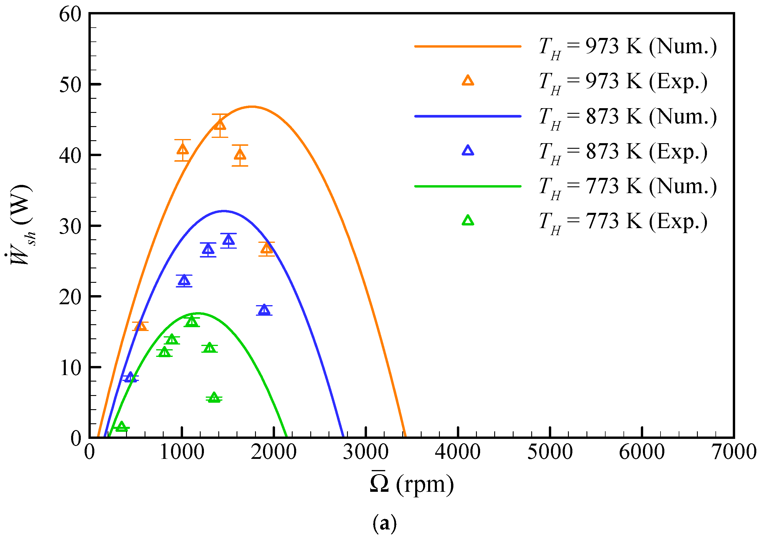
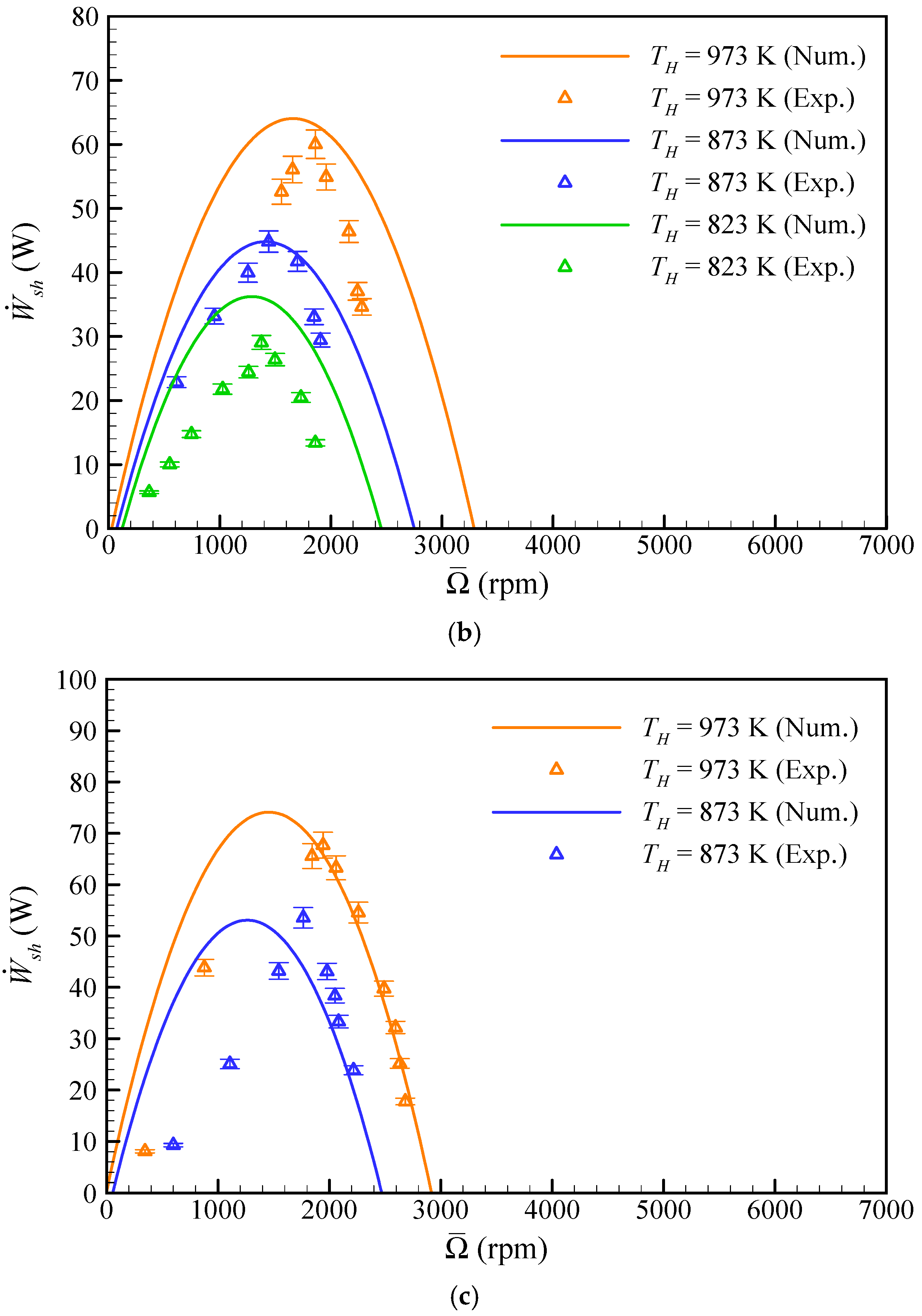
At 4-bar charged pressure, the prototype Stirling engine generates 16-44 W shaft power in the temperature span of 773–973 K. Meanwhile, numerical results according to the proposed model show 17–47 W within the same temperature. As the working conditions are elevated to 8-bar charged pressure and 973-K heating temperature, the shaft power of the designed engine is able to achieve 68 W while predicted power is 74 W. Close agreements between the experimental results and the numerical predictions were found.
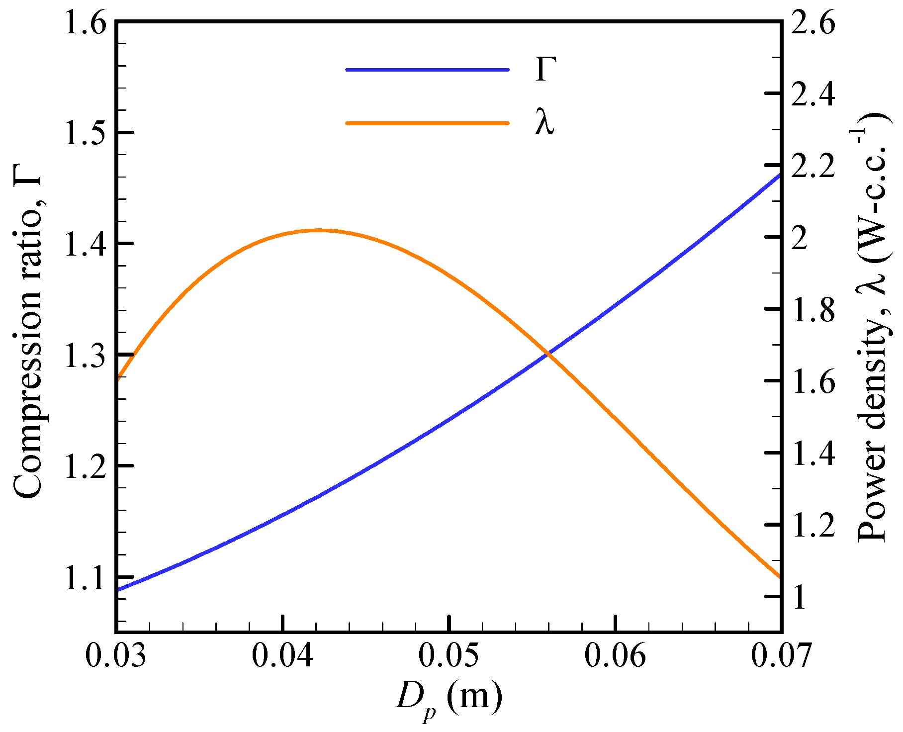
(3)
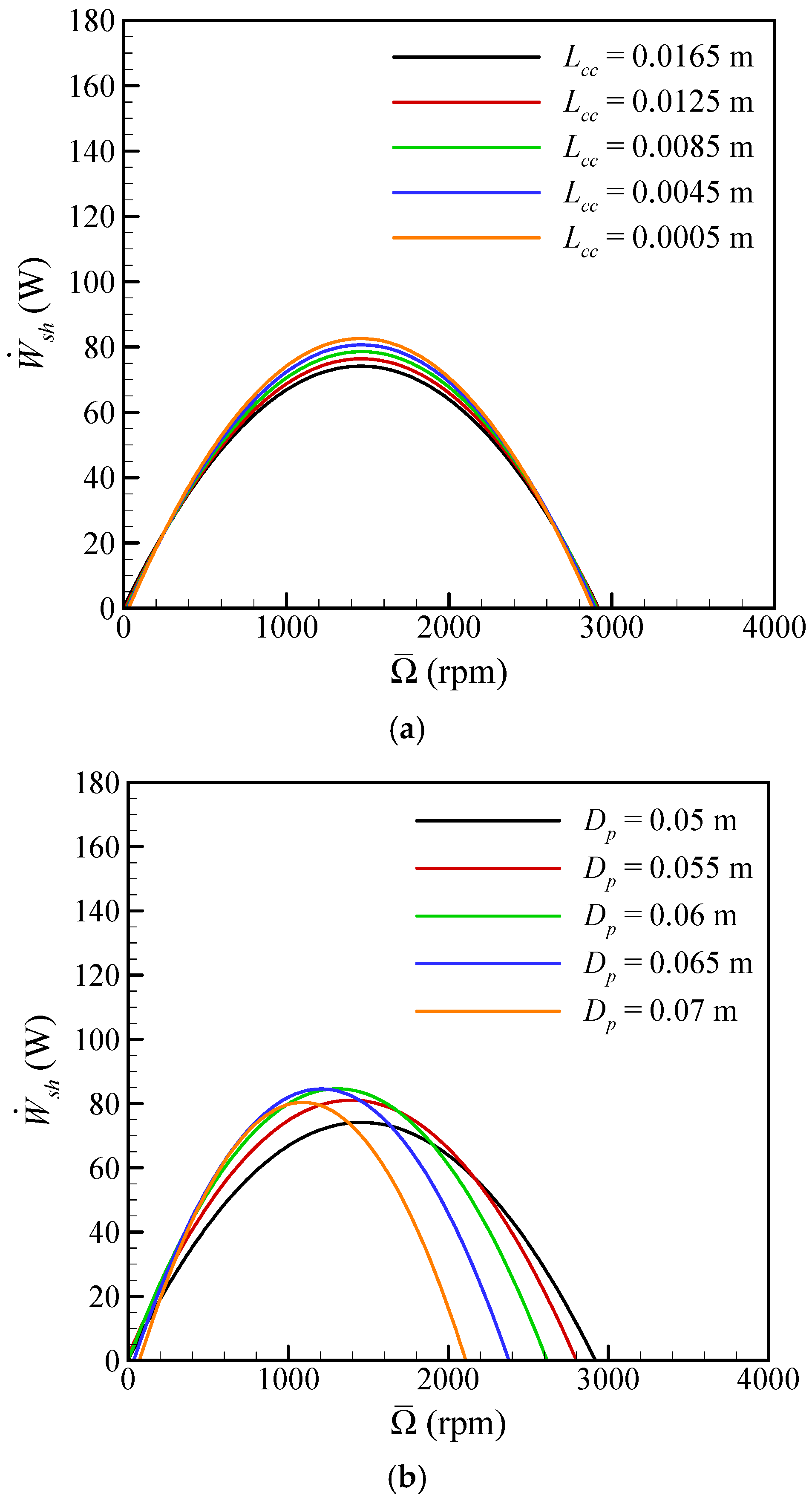
By means of parametric study on the compression chamber, shaft power is increased with smaller clearance. It was observed that optimal piston diameters corresponding to maximum shaft power and maximum power density are 0.06 and 0.042 m, respectively. It was deduced that the power density of the moderate-temperature-differential Stirling engine may achieve 2 W-c.c.−1.
(4)
The present study successfully developed a moderate-temperature-differential Stirling engine which is well suitable for development of the compact engines. The compact property of the engine is a criterion to be competitive in engineering applications.

Author Contributions

Conceptualization, C.-H.C.; methodology, C.-H.C. and J.-S.H.; validation, C.-H.C. and J.-S.H.; formal analysis, C.-H.C.; investigation, C.-H.C. and J.-S.H.; resources, C.-H.C.; data curation, J.-S.H.; writing—original draft preparation, J.-S.H.; writing—review and editing, C.-H.C.; supervision, C.-H.C.; project administration, C.-H.C.; funding acquisition, C,-H.C. All authors have read and agreed to the published version of the manuscript.

Funding

This research was funded by the Ministry of Science and Technology, Taiwan, under Grant MOST 106-2221-E-006 -125 -MY3.

Conflicts of Interest

The authors declare no conflict of interest.

Nomenclature

VariablesAbbreviations
Aarea (m2)
c1, c2constants of friction power equation
cp, cvconstant-pressure and constant-volume specific heat (J-kg−1-K−1)
Ddiameter (m)
ffriction factor
Ifmoment inertial of flywheel (kg-m2)
Lcc, Lceclearance length of compression and expansion chamber (m)
mmass (kg)
NuNusselt number
ppressure (Pa)
paveaverage pressure of working zone (Pa)
pchcharged pressure (Pa)
Δ p pressure drop (Pa)
Q ˙ heat transfer input (W)
Q ˙ n e t sum of heat transfer rate in all chambers (W)
Rconstgas constant (J-kg−1-K−1)
ReReynolds number
Ttemperature (K)
THheating temperature of Stirling engine (K)
Vvolume (m3)
vvelocity (m-s−1)
W ˙ d r i ,   W ˙ f r i ,   W ˙ s h driving, friction and shaft power (W)
ydisplacement (m)
Greek SymbolsAbbreviations
α angular acceleration (rad-s−2)
Γ compression ratio
λ power density (W-c.c.−1)
θ crank angle (rad)
τ s h shaft torque (N-m)
ω angular velocity (rad-s−1)
Ω ¯ rotation speed (rpm)
SubscriptAbbreviations
b, c, eback, compression, and expansion chamber
d, pdisplacer and piston
h, k, rheater, cooler, and regenerator chamber
in, outinlet and outlet on the boundary

References

  1. Singh, U.R.; Kumar, A. Review on solar Stirling engine: Development and performance. Therm. Sci. Eng. Prog. 2018, 8, 244–256. [Google Scholar] [CrossRef]
  2. Thombare, D.; Verma, S. Technological development in the Stirling cycle engines. Renew. Sust. Energ. Rev. 2008, 12, 1–38. [Google Scholar] [CrossRef]
  3. Shufat, S.A.; Kurt, E.; Cinar, C.; Aksoy, F.; Hançerlioğulları, A.; Solmaz, H. Exploration of a Stirling engine and generator combination for air and helium media. Appl. Therm. Eng. 2019, 150, 738–749. [Google Scholar] [CrossRef]
  4. Cheng, C.H.; Yang, H.S. Optimization of geometrical parameters for Stirling engines based on theoretical analysis. Appl. Energy 2012, 92, 395–405. [Google Scholar] [CrossRef]
  5. Cinar, C.; Yucesu, S.; Topgul, T.; Okur, M. Beta-type Stirling engine operating at atmospheric pressure. Appl. Energy 2005, 81, 351–357. [Google Scholar] [CrossRef]
  6. Aksoy, F.; Karabulut, H.; Çınar, C.; Solmaz, H.; Özgören, Y.Ö.; Uyumaz, A. Thermal performance of a Stirling engine powered by a solar simulator. Appl. Therm. Eng. 2015, 86, 161–167. [Google Scholar] [CrossRef]
  7. Meijer, R.J. The Philips hot gas engine with rhombic drive mechanism. Philips Tech. Rev. 1959, 20, 245–276. [Google Scholar]
  8. Erol, D.; Caliskan, S. Comparative study on the performance of different drive mechanisms used in a beta type Stirling engine through thermodynamic analysis. Int. J. Automot. Technol. 2019, 8, 44–60. [Google Scholar] [CrossRef]
  9. Hirata, K.; Iwamoto, S.; Toda, F.; Hamaguchi, K. Performance evaluation for a 100 W Stirling engine. In Proceedings of the 8th International Stirling Engine Conference, Faculty of Engineering, University of Ancona, Ancona, Italy, 27–30 May 1997; pp. 19–28. [Google Scholar]
  10. Ni, M.; Shi, B.; Xiao, G.; Peng, H.; Sultan, U.; Wang, S.; Luo, Z.; Cen, K. Improved Simple Analytical Model and experimental study of a 100 W β-type Stirling engine. Appl. Energy 2016, 169, 768–787. [Google Scholar] [CrossRef]
  11. Jadhao, J.; Thombare, D. Review on exhaust gas heat recovery for IC engine. Int. J. Eng. Innov. Technol. 2013, 2, 93–100. [Google Scholar]
  12. Song, Z.; Chen, J.; Yang, L. Heat transfer enhancement in tubular heater of Stirling engine for waste heat recovery from flue gas using steel wool. Appl. Therm. Eng. 2015, 87, 499–504. [Google Scholar] [CrossRef]
  13. Ramesh, U.; Kalyani, T. Improving the efficiency of marine power plant using Stirling engine in waste heat recovery systems. Int. J. Innov. Res. Dev. 2012, 1, 449–466. [Google Scholar]
  14. Durcansky, P.; Nosek, R.; Jandacka, J. Use of Stirling Engine for Waste Heat Recovery. Energies 2020, 13, 4133. [Google Scholar] [CrossRef]
  15. Aladayleh, W.; Alahmer, A. Recovery of exhaust waste heat for ICE using the beta type stirling engine. J. Energy 2015, 2015, 495418. [Google Scholar] [CrossRef] [Green Version]
  16. Wang, K.; Sanders, S.R.; Dubey, S.; Choo, F.H.; Duan, F. Stirling cycle engines for recovering low and moderate temperature heat: A review. Renew. Sust. Energ. Rev. 2016, 62, 89–108. [Google Scholar] [CrossRef] [Green Version]
  17. Sripakagorn, A.; Srikam, C. Design and performance of a moderate temperature difference Stirling engine. Renew. Energ. 2011, 36, 1728–1733. [Google Scholar] [CrossRef]
  18. Kropiwnicki, J.; Furmanek, M. A Theoretical and Experimental Study of Moderate Temperature Alfa Type Stirling Engines. Energies 2020, 13, 1622. [Google Scholar] [CrossRef] [Green Version]
  19. Cheng, C.H.; Tan, Y.H. Numerical Optimization of a Four-Cylinder Double-Acting Stirling Engine Based on Non-Ideal Adiabatic Thermodynamic Model and SCGM Method. Energies 2020, 13, 2008. [Google Scholar] [CrossRef] [Green Version]
  20. Caetano, B.C.; Lara, I.F.; Borges, M.U.; Sandoval, O.R.; Valle, R.M. A novel methodology on beta-type Stirling engine simulation using CFD. Energy Convers Manag. 2019, 184, 510–520. [Google Scholar] [CrossRef]
  21. Cheng, C.H.; Chen, Y.F. Numerical simulation of thermal and flow fields inside a 1-kW beta-type Stirling engine. Appl. Therm. Eng. 2017, 121, 554–561. [Google Scholar] [CrossRef]
  22. Gedeon, D.; Wood, J. Oscillating-Flow Regenerator Test Rig: Hardware and Theory with Derived Correlations for Screens and Felts; NASA Contractor Report 198442; NASA Center for Aerospace Information: Washington, DC, USA, 1996.
  23. Tanaka, M.; Yamashita, I.; Chisaka, F. Flow and heat transfer characteristics of the Stirling engine regenerator in an oscillating flow. JSME Int. J. 1990, 33, 283–289. [Google Scholar] [CrossRef] [Green Version]
  24. Yang, H.S.; Cheng, C.H.; Huang, S.T. A complete model for dynamic simulation of a 1-kW class beta-type Stirling engine with rhombic-drive mechanism. Energy 2018, 161, 892–906. [Google Scholar] [CrossRef]
  25. Cheng, C.H.; Yang, H.S.; Chen, H.X. Development of a beta-type Stirling heat pump with rhombic drive mechanism by a modified non-ideal adiabatic model. Int. J. Energy Res. 2020, 44, 5197–5208. [Google Scholar] [CrossRef]
  26. Kuehl, H.D. Numerically Efficient Modelling of Non-Ideal Gases and their Transport Properties in Stirling Cycle Simulation. In Proceedings of the 17th International Stirling Engine Conference and Exhibition (ISEC), Newcastle Upon Tyne, UK, 24–26 August 2016; pp. 572–579. [Google Scholar]
  27. Moffat, R.J. Contributions to the theory of single-sample uncertainty analysis. ASME Trans. J. Fluids Eng. 1982, 104, 250–258. [Google Scholar] [CrossRef] [Green Version]
Figure 1. Schematic of beta-type Stirling engine with rhombic drive mechanism.
Energies 13 06029 g001
Figure 2. Calculation flow chart of theoretical model.
Energies 13 06029 g002
Figure 3. Prototype Stirling engine and experimental apparatus built in this study: (a) picture of studied Stirling engine prototype; (b) experimental apparatus.
Energies 13 06029 g003
Figure 4. Dynamic simulation of engine behavior in response to variation in shaft torque: (a) average rotation speed; (b) shaft power, friction power, driving power, and net heat input.
Energies 13 06029 g004aEnergies 13 06029 g004b
Figure 5. Numerical and experimental performance curve of the deigned Stirling engine at charged pressure of 4–8 bar and heating temperature of 773–973 K: (a) 4-bar charged pressure; (b) 6-bar charged pressure; (c) 8-bar charged pressure.
Energies 13 06029 g005aEnergies 13 06029 g005b
Figure 6. Parametric analysis of clearance length of compression chamber and piston diameter under 8-bar charged pressure and 973-K heating temperature: (a) effect of clearance length of compression chamber; (b) effect of piston diameter.
Energies 13 06029 g006
Figure 7. Effect of piston diameter on the compression ratio and power density under 8-bar charged pressure and 973-K heating temperature.
Energies 13 06029 g007
Table 1. Design parameters of the Stirling engine.
Displacer Bore × Stroke0.07 × 0.0186 m
Piston Bore × Stroke0.05 × 0.02 m
Expansion chamber clearance length, Lce0.003 m
Compression chamber clearance length, Lcc0.0165 m
Diameter of back chamber rod, Db0.004 m
Number of heater channels24
Length of heater channel0.2345 m
Cross-sectional area of heater channel8.067 × 10−6 m2
Number of cooler channels90
Length of cooler channel0.03 m
Cross-sectional area of cooler channel1.647 × 10−6 m2
Volume of regenerator, Vr1.679 × 10−5 m3
Flywheel inertial, If7.123 × 10−3 kg-m2
Compression ratio, Γ1.242
Charged pressure, pch4–8 bar
Heating temperature, TH773–973 K
Table 2. Transport properties of gas at 873 K and 6 bar [26].
GasDynamic ViscosityThermal Conductivity
Air3.918 × 10−5 Pa-s6.099 × 10−2 W-m−1-K−1
Nitrogen3.703 × 10−5 Pa-s5.844 × 10−2 W-m−1-K−1
Heliuim4.073 × 10−5 Pa-s3.236 × 10−1 W-m−1-K−1
Hydrogen1.837 × 10−5 Pa-s7.272 × 10−1 W-m−1-K−1
Table 3. Uncertainty analysis for measured parameters.
ParametersTypical Value, xUncertainty a, δxRelative Uncertainty, δx/x (%)
pch4–8 bar0.12 bar2
TH773–973 K6.5 K0.83
τsh0.02–0.28 N-m0.004 N-m2.7
Ω ¯ 350–2700 rpm20 rpm1.3
W ˙ s h 1–68 W-3.7 b
a All estimated with 95% confidence. b δ   W   ˙ sh /   W   ˙ sh = [ ( δ p ch / p ch ) 2 + ( δ T H / T H ) 2 + ( δ τ sh / τ sh ) 2 + ( δ   Ω   ¯ /   Ω   ¯ ) 2 ] 1 / 2 .
Table 4. Comparisons of developed beta-type Stirling engines.
AuthorWorking GasCharged PressureHeating TemperaturePower Density
PresentHelium8 bar973 K1.725 W-c.c.−1
Aksoy et al. [6]Helium5 bar873 K0.553 W-c.c.−1
Hirata et al [9]Nitrogen8 bar923 K0.737 W-c.c.−1
Ni et al. [10]Helium29.6 bar808 K1.800 W-c.c.−1
Publisher’s Note: MDPI stays neutral with regard to jurisdictional claims in published maps and institutional affiliations.

