Abstract
This study proposes to use gas-fired boilers as peak shaving heat sources in heating substations due to their capability to increase the reliability, flexibility and heat capacity without the need to change the district heating network (DHN). However, the design and operational requirements with different connection modes for this kind of DH system are still not clear. This paper presents a systematic study on this kind of DH system, analyzes the connection modes of series and parallel connections between the gas-fired boilers and the heat exchangers. For each connection mode, we figured out the thermal balances and obtained the design and operational parameters including the supply temperatures of the heat exchangers, gas-fired boilers and their variations under different network temperature levels and the base load ratios (β). Under the series connection mode, the design supply temperature of the heat exchangers has no relation with the design peak shaving flow ratio (ω′); it decreases linearly along with smaller β, and the decreasing slope is higher with bigger temperature difference (Δt) of the DHN. However, the design supply temperatures of gas-fired boilers increase linearly when β and/or ω′ are smaller, and the increasing speed is proportional to Δt. For the parallel connection mode, the design supply temperatures of the heat exchangers and gas-fired boilers are all affected by β, ω′ and Δt. The former decreases when β and/or ω′ are smaller, while the latter increases at the same time. Finally, the design peak shaving flow ratio ω′ are determined for the peak boilers with series and parallel connection modes. The study provides a theoretical basis for the design and operation of the DH system with peak heating boilers in substations in order to reach a lower investment and higher efficiency.
1. Introduction
Nowadays, most of the district heating (DH) systems have multiple heat sources, including the base load heat sources, e.g., combined heat and power (CHP) plants or large heat only boilers (HOB), and the peak shaving heat sources located either in the base plant or in the heating substations. Those DH systems are referred to as the combined DH systems in this paper to differentiate from the DH systems with only one heat pant or with multiple heat plants but operated independently. A detailed discussion on different configurations of combined DH systems can be found in [1]. This paper mainly focuses on the combined DH system with peak shaving gas-fired boilers in heating substations. Although the peak shaving boilers are decentralized, they are connected to the DH system and thus different from the detached heating systems, which are often used in the areas where it is not economically feasible to connect to a district heating network (DHN). For a combined DH system, in the beginning and end of the heating season, the base load heat source provides the whole heat demand with high average efficiency and low operating cost; but during the cold period, when the base load heat production is insufficient, peak shaving heat sources will be operated [1] to satisfy the supply water temperature and heat demand.
In the 1960s, Russia began to design and operate the combined DH systems [2]. Later, in the 1970s, DH systems with waste incineration or combined heat and power (CHP) plants as the base load heat plant and oil-fired boilers as peak shaving heat sources emerged in Nordic countries [2]. For example, in Helsinki, DH provides more than 90% of the heating demand that is provided by several CHP plants and one large-scale water source heat pump [3]. In addition, gas-fired boilers are more often used in DH, while in Norway, the gas and oil boilers are widely used as peak shaving heat sources for DHN. Kauko et al. [4] and Barelli et al. [5] argued that it would be very meaningful to use the gas-fired boilers to adapt the variable heat demand of the CHP plant and thus it would benefit from being studied further. However, it is also very important to analyze the system’s comprehensive performance in terms of the energy, economy and the environment [6].
At the beginning of the 1990s, the combined DH system was studied by a few researchers in China; they started summarizing the calculation and design methods for a combined DH system with CHP and coal-fired boilers for peak load shaving [7,8]. Along with the development, the combined DH system with multiple decentralized peak heating sources is more often used when planning and retrofitting DH systems in China. Huang [9] and Wang et al. [10] proposed a combined DH system with peak-shaving gas-fired boilers in the heating substations on the secondary side of the DHN. Then some researchers started studying the operating modes and energy-saving potential of this kind of DH system [11,12]. To conclude, the combined DH systems with multiple heat sources are becoming increasingly popular in the DH sector around the world [13,14].
In general, DH system with multiple heat sources is superior to the DH with only one single heat plant or with multiple independent heat plants because it can increase the heating reliability thanks to the backup capacity of the peak shaving heat sources, reduce the environmental impact through optimal planning and operation of the heat sources, and increase the total efficiency and reduce the operating cost of the DH system. In previous decades, big peak shaving heat sources were usually designed and installed in the primary network or in the base load heat plant. Nowadays, the higher DH demands and peak loads require the development of the DHN and the heat sources, but the huge investment to replace even part of the network could be a big problem. This issue can also be solved by the installation of the PBs in substations at the secondary side near the heat users [15], since it can extend the heating capacity to compensate the increasing user demand without the need to build a new pipeline system or to retrofit the already existing DHN. Therefore, this kind of DH technology received growing publicity in DH engineering. Previous studies [3,12,13,14] provide good bases for planning and operating DH in terms of energy and economy. However, many studies are application-oriented and the systematic analysis for this kind of DH system is still lacking regarding the detailed design and operational requirements. Different connection modes of the peak-shaving gas-fired boilers are ignored, which will dramatically affect the system design and operation. Moreover, decentralized peak shaving-gas fired boilers in the secondary side are usually installed and operated only according to the first law of thermodynamics without consideration of the second law of thermodynamics. This can lead to a waste of investment and the low overall efficiency of the peak boilers (PB) and sometimes may not satisfy the required supply temperatures. Moreover, few studies consider the very important parameter called peak shaving flow ratio, reflecting the ratio of the flowrate entering the PB and sheat exchanger. Determination of this parameter heavily affects the pumping energy consumption of the combined DH system.
Therefore, a comprehensive and systematic study of the DH system with peak-shaving gas-fired boilers in heating substations is necessary in order to provide a theoretical and solid basis to support the design and operation of a real system. This paper focuses on peak-shaving heating with gas-fired boilers in heating substations, and tries to solve the problem of how to determine the design and operational parameters with series and parallel connection modes of the PBs considering different supply and return temperature levels in the DHN. Specifically, this study analyzed the connection modes based on series and parallel connections between the boilers and the heat exchangers in substations. For each connection mode, we carried out the simulation procedures and performed calculations based on the mass and heat balances and the second law of thermodynamics for the given design conditions. The design parameters of the peak boilers including the supply temperatures of the heat exchangers and PBs were determined, and their variations with the outdoor temperatures in a case study were analyzed. Then the determination method for the peak shaving flow ratio was summarized for both connection modes. The research results can help to understand the real operation mechanism of the DH system with peak boilers in the secondary side, and provide the theoretical basis for determining the operation strategy of this kind of DH system.
2. Connection Modes of the Peak Boilers and System Characteristics
2.1. Connection Modes between Peak Boilers (PB) and Heat Exchangers
This paper proposes two connection modes according to the connections between the gas-fired PBs and the heat exchangers in the heating substations, namely series and parallel connection modes, as shown in Figure 1 and Figure 2.
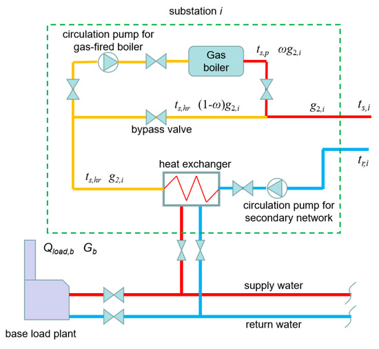
Figure 1.
DH system with gas-fired PBs in all heating substations with series connection modes.
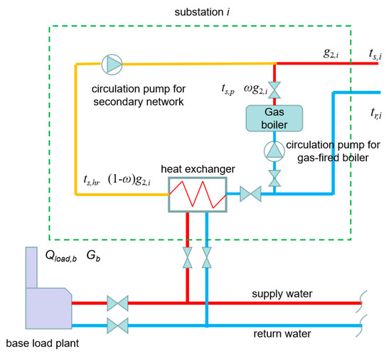
Figure 2.
DH system with gas-fired PBs in all heating substations with parallel connection modes.
Figure 1 indicates the series connection mode. For heating substation i, the gas-fired PB is placed after the heat exchanger with a series connection, and a bypass pipe is connected to the PB. The return water from the heat user in the secondary side is preheated by the base load heat plant through the heat exchanger, and then the water flow is divided into two streams: one stream with flowrate ωg2,i enters the gas-fired boilers for reheating, while the other flows through the bypass pipe. The two water streams mix again at the outlet of the PB, but the value of ω, which is called peak shaving flow ratio should be determined to minimize the pumping cost and the heat output of PB should be controlled in order to provide supply water with the required temperature.
The peak shaving flow ratio for the heating substation i is defined as,
where gp,i and g2,i are the flow rates of the circulation pumps for the peak-shaving gas-fired boiler and for the secondary network of substation i, kg/s.
Therefore, the peak shaving flow ratio under design condition for each heating substation can be written as,
where and are the flow rates of the circulation pumps for the peak-shaving gas-fired boiler and for the secondary network of substation i under the design condition, kg/s. Design peak-shaving flow ratio is a very important parameter for the DH system with PBs in the heating substation. In this study, we assume that the peak shaving flow ratio for each heating substation is equal to the peak shaving flow ratio for the whole DH system, i.e., .
Figure 2 shows the parallel connection mode. For heating substation i, the return water from the heat user in the secondary side is divided into two streams. One stream enters the heat exchanger with a flowrate of (1 − ω)g2,i, while the other flows into the gas-fired PB with a flowrate of ωg2,i. It is clear that the PB and heat exchanger will heat up the return water independently, and the two streams mix with each other at the outlet of the PB, and the value of ω should be determined and the PB be controlled in order to provide supply water with the required temperature. It can be concluded that the water stream entering the PB in series mode is preheated by the heat exchanger, while the water stream entering PB in parallel mode is the return water without preheating. This makes the flowrate and water temperature variations and operation requirements quite different for the two connection modes.
2.2. Base Load Ratio
The design heat load of a DH system with PBs in the secondary side can be written as
where and are the design heat load of the base load heat plant and the PBs, W. The base load ratio β can be defined as
and thus the peak load ratio α = 1 − β.
In this study, we assume that the base load ratio for each heating substation is equal to the base load ratio of the DH system, namely,
where βi is the base load ratio for the ith substation; is the design heat load of the heat exchanger in the ith substation, W; is the design heat load of the ith substation, W.
The base load ratio β is influenced by the characteristics of the base load plant and the PBs, e.g., the initial investment and operating cost for them, as well as the configuration of the base load heat plant and the PBs. The derivation of optimal base load ratio with CHP as base plant can be found in [12].
2.3. System Characteristics
The DH system with peak shaving gas-fired boilers in heating substations has the following characteristics depending on whether the system is newly built or retrofitted. For the newly built system: (1) the diameter of the primary DHN can be reduced because the primary DHN only provides the base load, and this will reduce the initial investment of the DHN; (2) the peak shaving heat sources are installed in heating substations, therefore even the most disadvantageous accident happens and the heat supply from the primary DHN is cut down, the gas-fired PBs can still provide a certain level of the district heat to reduce the impact of the accident and prolong the repair time; (3) the gas-fired PB has good flexibility and higher efficiency, which is slightly affected by the heat demand. As for the retrofitted system, the system can also provide back-up capacity for the base load heat plant and thus reduce the impact of the accident. In addition, the most obvious advantage is to extend the heating capacity of the existing DH system without changing old pipelines in the primary DHN. Of course, the use of gas-fired boilers will add extra investment and operating cost to the boilers and gas supply pipes, however the overall economic performance can be better with proper base load ratio and compared to the DH system with only base load heat plant [12].
3. Thermal Balance of the DH System with Peak Shaving Gas-Fired Boilers in Heating Substations
The use of PBs in substations introduces the design and operating parameters of the gas-fired boilers, which will affect the design and operating parameters of the heat exchanger. In this paper, we analyze the relationship between those parameters and the base load ratio β as well as the design peak shaving flow ratio ω′. For this purpose, the thermal balance of the DH system should first be established.
During the whole heating season, the thermal balance of the DH system can be written as
where Qload,b is the heat load of the base load heat plant at outdoor temperature tout, W; Qhr is the heat load of all heat exchangers, W; qhr,i is the heat load of the heat exchanger in the ith substation, W.
When the peak heating is not needed, the thermal balance is,
where Qnetwork is the heat load that users receive from the DHN, W; cwater is the specific heat capacity of water, 4186.8 J/(kg·°C); ts, tr are the supply and return water temperatures of the secondary DHN at outdoor temperature tout, °C.
However, during the peak heating season, the thermal balance of the whole DH system will take the form
where is the design heat load of all heat exchangers, W; is the design heat load of the heat exchanger in the ith substation, W; Qload,p is the peak shaving heat load during the peak heating period at outdoor temperature tout, W.
3.1. Design Supply Water Temperatures of Heat Exchanger and the Gas-Fired Boiler
According to the aforementioned thermal balances in Equations (6)–(8), we can obtain the supply water temperatures of heat exchangers and peak-shaving gas-fired boilers under working conditions when the outdoor temperature is tout and under design condition at outdoor temperature .
For series connection, the design heat load of all heat exchangers and all peak-shaving gas-fired boilers are,
According to the heat balance in the substation, Equations (9) and (10) can also be written as,
Then the design supply water temperature of the heat exchangers can be obtained from Equations (9) and (11),
Similarly, design supply water temperature of the gas-fired boilers can be deduced from Equations (10) and (12),
Figure 3 shows the variation of the design supply water temperature of the heat exchanger () with the base load ratio (β) and different DHN temperature levels for series connection. The selected temperature levels are = {85 °C, 70 °C} and = {[70 °C, 65 °C, 60 °C]; [55 °C, 50 °C, 45 °C]} in order to cover more real situations. It can be found that under series connection mode decreases linearly when β is smaller and the decreasing slope is only determined by the network temperature difference (Δt) and irrelevant from the design supply temperatures.
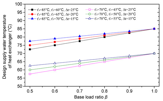
Figure 3.
Variation of design supply water temperature of the heat exchanger () with different network temperature levels and base load ratio (β) for series connection.
For safety and economic reasons, we assume that the highest supply water temperature of the gas-fired boilers is 135 °C. So the design supply temperature of the peak-shaving gas-fired boiler is affected not only by the base load ratio (β) and peak shaving flow ratio, but also it will be restricted by the maximum supply temperature of the gas-fired boilers. With this constraint and according to Equation (14), Figure 4 illustrates the variation of the design supply water temperature of the gas-fired boiler () with different DHN temperature levels, base load ratio β and design peak shaving flow ratio (ω′) for series connection. It can be concluded that when ω′ is chosen, decreases linearly with increasing value of β, and the decreasing speed of is only affected by the network temperature difference (Δt). In addition, increases rapidly when ω′ is decreasing, and the increasing speed is faster with bigger temperature differences. This also makes with low DH temperature levels can even be higher than those with high temperature levels, as indicated by the rectangle in Figure 4d, e.g., when β = 0.7 for , = {85 °C, 70 °C} with Δt = 15 °C compared with the situation of , = {70 °C, 45 °C} with Δt = 25 °C, for low DH temperature level is higher than that for the high temperature level.
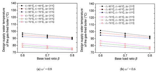
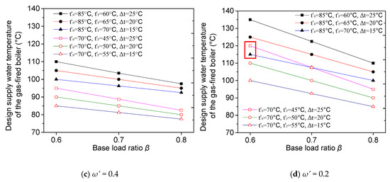
Figure 4.
Variation of the design supply water temperature of the PB () with different network temperature levels, base load ratio (β) and design peak shaving flow ratio (ω′) for series connection.
For the parallel connection mode, we can also obtain the design supply water temperatures for heat exchanger and the gas-fired boilers as follows.
It can be seen from Figure 5 that when the design peak shaving flow ratio ω′ = 1 − β, the design supply water temperatures of the heat exchangers are all equal to the design supply water temperature of the DHN and irrelevant to the temperature levels. When smaller ω′ is chosen, i.e., ω′ < 1 − β, then is lowered linearly with decreasing value of β, and the decreasing speed is faster for systems with larger temperature differences Δt. Note that ω′ can be further lowered provided higher temperature water can be supplied by the peak-shaving gas-fired boilers, but the highest supply temperature is restricted to 135 °C as explained before. For example, in Figure 5d, when ω′ = 0.1, is not defined for the DH system with an excessively low base load ratio since the required supply water temperature of the peak shaving gas-fired boiler is higher than 135 °C. On the other hand, ω′ cannot be larger than 1 − β, because should be smaller than the DHN design supply water temperatures, according to the second law of thermodynamics. The upper and lower constraints of ω′ are detailed in Section 3.2 and Table 1.
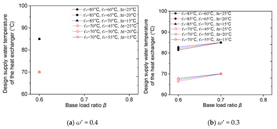
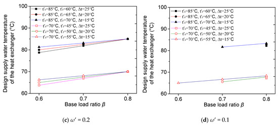
Figure 5.
Variation of the design supply water temperature of the heat exchanger () with different network temperature levels, base load ratio (β) and design peak shaving flow ratio (ω′) for parallel connection.

Table 1.
The supply water temperatures of the heat exchanger and peak shaving gas-fired boilers as well as the determination of the design peak shaving flow ratio ω′.
Figure 6 shows the variation of with different DHN temperature levels, base load ratio (β) and design peak shaving flow ratio (ω′) for parallel connection mode. Unlike the , varies with different temperature differences even when ω′ = 1 − β, and clearly is higher for bigger temperature differences within the same DHN supply temperature level. When ω′ < 1 − β, increases linearly with decreasing value of β, and the increasing speed is faster for the system with the larger temperature difference. This makes it possible for with lower temperature level to exceed that with higher temperature level, e.g., in Figure 6c, when β is smaller than 0.7 for , = {85 °C, 70 °C} with Δt = 15 °C compared with the lower temperature level of , = {70 °C, 45 °C} with Δt = 25 °C. In Figure 6d, ω′ is further lowered with the highest supply temperature restricted at 135 °C. On the other hand, ω′ cannot be larger than 1 − β, because in this case the mixed water temperature of heat exchanger and gas-fired boiler cannot meet the DHN requirement according to the heat balance and the second law of thermodynamics.
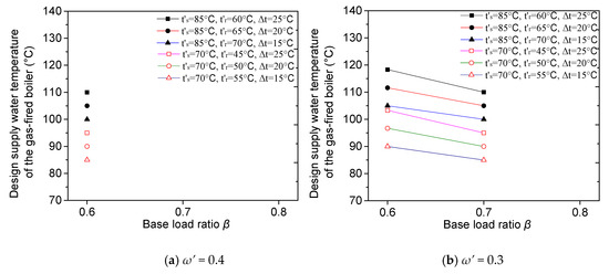
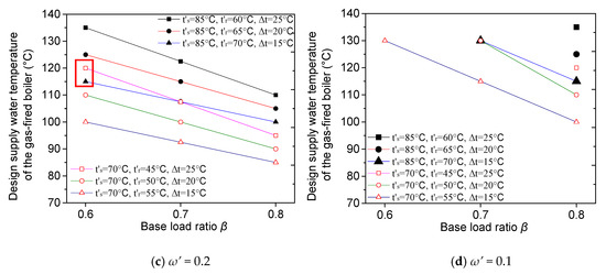
Figure 6.
Variation of the design supply water temperature of the PB () with different network temperature levels, base load ratio (β) and design peak shaving flow ratio (ω′) for parallel connection.
3.2. Supply Water Temperatures of Heat Exchanger and Gas-Fired PB under Working Conditions
In this section, working condition means the situation when outdoor temperature tout is higher than the design outdoor temperature . The calculation of the supply water temperatures of heat exchanger and gas-fired boiler depends on whether the peak heating period begins or not. Therefore, we can divide the heating season into two periods, i.e., during peak heating period when tout falls below the critical peak heating temperature [2] (peak heating is needed) and the period when peak heating is not needed.
3.2.1. During the Peak Heating Period
When peak heating starts, all heat exchangers are operated in full load and according to the second equation in Equation (8), for series connection we can obtain
Because = βQ’ and = (1 − β)Q′, the supply water temperature of the heat exchanger can be obtained via the following equation
In addition, the supply water streams of the heat exchanger and the gas-fired boiler will be mixed to reach the supply water temperature of ts, so the following heat balance exists in the heating substation
Therefore, the supply water temperature of the gas-fired boiler can be calculated by
The aforementioned results are for the series connection system, and similarly for the parallel connection mode, the supply water temperature of the heat exchanger is
However, the supply water temperature of the gas-fired boiler is the same as Equation (21) for parallel connection, because they have the same heat load balance in the heating substation during the peak heating period.
3.2.2. During the Heating Period When Peak Heating Is Not Needed
When peak heating is not needed, ts,hr = ts no matter for the series or parallel connection modes, and ts,p = 0 because gas-fired boilers are shut down.
In this section, we also show the variation of ts,hr and ts,p with the supply and return water temperature and outdoor temperature of a case DH system located in Dalian, China. The design outdoor temperature is −11 °C, the heating season is 150 days, and the heating degree days (HDD18) are 93.25 °C·d. The selected base load ratio β is 0.8, and the design supply and return water temperature are 70 °C and 45 °C. The heat supply of the DHN is controlled by changing the supply and return water temperature and as a result, the temperature differences.
The variation of ts,hr and ts,p with the outdoor temperature for series and parallel connection are shown in Figure 7 and Figure 8. The critical peak shaving temperature of the case DH system is −5.2 °C, when the relative heat load ratio equal to the base load ratio β = 0.8. This is also highlighted with an arrow and dotted line in these two figures. Therefore, the peak-shaving gas-fired boilers are not utilized when tout is higher than −5.2 °C, and naturally the supply water temperature of the heat exchanger is equal to ts, regardless of whether they are for series or parallel connection modes. However, when tout is lower than −5.2 °C, the peak shaving gas-fired boilers need to be activated. As shown in Figure 7, for series connection mode, ts,hr is irrelevant to the value of ω′, and it is lower than the required DHN supply temperature ts due to the insufficient heat supply from the base load heat source. This means that the gas-fired boilers must provide a hotter water stream (ω′g2,i) to make the mixed water meet the supply water temperature requirement. Further, the smaller the ω′ is, the higher the ts,p will be.
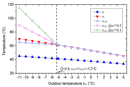
Figure 7.
Variation of supply water temperature of the gas-fired boiler (ts,p) and heat exchanger (ts,hr) with outdoor temperature under working condition for series connection.
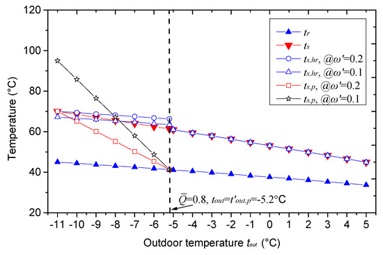
Figure 8.
Variation of supply water temperature of the gas-fired boiler (ts,p) and heat exchanger (ts,hr) with outdoor temperature under working condition for parallel connection.
For parallel connection mode, ts,hr is influenced by the value of ω′, and it is higher with saller ω′. When peak heating begins, ts,hr is higher than the required DHN supply temperature ts, because part of the return water (ω′g2,i) flows into the gas-fired boiler, and the rest water will be heated up to a higher temperature since it received the same amount of heat (and also maximum heat) from the base load heat source. This means that the peak shaving gas-fired boiler does not need to provide high-temperature water at the beginning of the peak heating period when tout is not too low. In addition, when ω′ = 1 − β, ts,p is always lower than the ts, and they are equal only under design working conditions at outdoor temperature of . When ω′ < 1 − β, e.g., in this case ω′ = 0.1, the water flow in the gas-fired boiler is smaller and thus ts,p increases faster but ts,hr increases slower with decreasing tout compared to the situation of ω′ = 0.2, which makes ts,p and ts,hr intersect with each other during the peak heating period. In any case, the mixed water flow should meet the required temperature of the DHN according to the thermal balance and the second law of thermodynamics.
From another point of view, when peak heating begins, we have the following equation for both series and parallel connection modes.
Furthermore, the design heat load of all heat exchangers can be written as , therefore,
According to Equation (24), we conclude an important property for both series and parallel connection modes, namely the fact that the temperature difference between the supply water temperature of the heat exchanger and the return water temperature is a constant which equals the design temperature difference of and . Therefore, we can use this property to calculate the supply temperature of the heat exchanger without knowing β and ω′, but only with information of tr.
3.3. Discussion on the Design Peak-Shaving Flow Ratio
Apart from the supply water temperatures, the design peak shaving flow ratio ω′ is another parameter that heavily affects the DH system from the perspective of the pumping energy consumption of circulation water pump for peak-shaving gas-fired boilers and for the secondary DHN. If the value of ω′ is too large, the pumping energy consumption of the peak-shaving circulation pump will be increased, otherwise the supply temperature of gas-fired boilers will be dramatically increased due to the small flow rate at a certain heat output. Therefore, ω′ should have a proper interval of [, ] in which the pumping cost is reasonable and the supply water temperature of the gas-fired boiler is not exceeding the restricted value.
is affected by the base load ratio β, for series connection [14],
Similarly, for parallel connection,
Theoretically, the for series connection can be 1, but in order to fully utilize the heating capacity of the peak shaving gas-fired boilers and to reduce the peak-shaving pumping cost, it is recommended to use the smallest possible peak shaving flow ratio in real life (). For parallel connection, the design supply water temperature of the gas-fired boilers should not be lower than the design supply water temperature of the heat exchanger, i.e., ≥ , otherwise the return water may not be heated up to the required supply temperature of ts. Thus, the following inequality should exist,
Namely
Equation (28) can take the form
which means that
Equation (30) provides an important indication that the maximum peak-shaving flow ratio for parallel connection is equal to the peak load ratio. The aforementioned results are summarized and shown in Table 1. As shown in Table 1, ω′ can be obtained when the other design parameters are determined, but according to Equation (1), the real peak shaving flow ratio under working conditions can be changed but should not exceed the scope of ω′.
4. Conclusions
This paper carried out a comprehensive and systematic research on the DH system with peak shaving gas-fired boilers in heating substations. The objective is to derive the thermal balances and operational parameters, which are indispensable for the system design and operation optimization. Firstly, we analyzed the connection modes of the gas-fired boiler to the heat exchanger in the substation, including series and parallel connections, and summarized their differences in the system characteristics and thermal balances. Secondly, the design and operating parameters, e.g., the supply water temperatures of the peak-shaving gas-fired boilers and the heat exchangers as well as the peak shaving flow ratio are studied. The influences of outdoor temperature, base load ratio, supply and return DH water temperatures on those operating parameters were also analyzed. Finally, we establish the thermal balances for the whole DH system, and determined the analytical formula for operating this kind of DH systems. The main results of the study are as following.
- Under series connection mode, the design supply temperature of heat exchangers decreases linearly while the design supply temperature of increases linearly with decreasing value of β; and their variation speeds are only proportional to the network temperature difference (Δt) but has no relation to the network temperature levels. This makes with low DH temperature level but at bigger Δt can even be higher than that with high temperature level at smaller Δt.
- For the parallel connection mode, when the design peak shaving flow ratio ω′ = 1 − β, are equal to the design supply water temperature of the DHN and irrelevant to the Δt. Unlike the , varies with different Δt even when ω′ = 1 − β. When ω′ < 1 − β (Note that ω′ can not be larger than 1 − β according to the thermal balance), decreases linearly but increases linearly when β is smaller, and the increasing speed is faster for the system with the bigger Δt. This also makes it possible for with lower temperature level to exceed that with higher temperature level.
- After examining the variation of those parameters under working conditions with arbitrary tout, an important property for both series and parallel connection modes was revealed, i.e., the temperature difference between the supply water temperature of the heat exchanger ts,hr and the return water temperature tr is a constant which equals to ( − ).
- This study proposed a very important variable called the design peak shaving flow ratio ω′, which heavily affects the system from the perspective of the pumping energy consumption. If the value of ω′ is too large, the pumping energy consumption of the peak-shaving circulation pump will be increased, otherwise the supply temperature of gas-fired boilers will be dramatically increased due to the small flow rate at a certain heat output. There exists an upper and lower limit of ω′ for both connection modes. The upper limits of ω′ are 1 and (1 − β) for series and parallel connection modes, but the lower limits should be determined according to the chosen of other parameters, e.g., , , and . It is recommended to use the smallest possible peak shaving flow ratio for both series or parallel connection modes in order to save pumping energy.
The obtained results can be used in the design of peak heating installations and contribute to the efficiency improvement taking full use of the existing district heating network DHN. Future work is necessary to analyze the optimal operating strategies and pumping energy-saving potential based on the derived thermal balances and operating parameters.
Author Contributions
Data curation, X.L. and J.L.; Formal analysis, H.W.; Methodology, H.W.; Resources, X.L., X.W. and E.T.; Supervision, L.D. and R.L.; Writing—review & editing, E.T. and L.Y. All authors have read and agreed to the published version of the manuscript.
Funding
This research was funded by Ministry of Science and Technology, China, grant number 2016YFE0114500, and Academy of Finland, grant number 299186 and 323026. The APC was funded by Academy of Finland.
Acknowledgments
The authors appreciate the supports from Ministry of Science and Technology, China and Academy of Finland. We also thank the anonymous referees for their valuable suggestions and detailed comments based on which we improve our manuscript.
Conflicts of Interest
The authors declare no conflict of interest.
Nomenclature
| a, coefficient of the heat transfer equation of radiators. |
| b, index of the heat transfer equation of radiators. |
| cwater, specific heat capacity of water; 4186.8 J/(kg·°C). |
| F, radiation area of the radiators; m2. |
| Fhr, heat exchange area; m2. |
| Gb, flow rate of the base load heat plant; kg/s. |
| Gp, flow rate of the circulation pump for peak shaving gas-fired boiler; kg/s. |
| G1, flow rate in the primary network; kg/s. |
| G2, flow rate of the circulation pump for secondary network; kg/s. |
| g2,i, flow rate in the ith heating substation; kg/s. |
| , relative flow rate ratio in primary network. |
| , relative flow rate ratio in secondary network. |
| , relative flow rate ratio of primary side in the ith substation. |
| , relative flow rate ratio of secondary side in the ith substation. |
| , relative flow rate ratio in the secondary side of the heat exchanger. |
| , relative heat transfer coefficient of water-water heat exchanger. |
| , relative heat transfer coefficient of the heat exchanger in the ith substation. |
| Q′, design heat load of the whole DH system; W. |
| qload,b,i, heat load supplied from the base load heat plant to the ith substation; W. |
| qload,i, heat load of the ith substation; W. |
| Qload,b, heat load of the base load heat plant; W. |
| Qload,p, peak shaving heat load during the peak heating period; W. |
| Qhr, heat load of all heat exchangers; W. |
| Qnetwork, heat load that users receive from the network; W. |
| Qbuilding, heat load of the buildings in the network; W. |
| Qradiator, heat releasing load of radiators in the network; W. |
| q, volumetric heat index of the buildings; W/m3. |
| qhr,i, heat laod of heat exchanger in the ith substation; W. |
| , relative heat load ratio in primary network. |
| , relative heat load ratio in secondary network. |
| ts, supply water temperature of the secondary network; °C. |
| ts,hr, supply water temperature of the heat exchanger; °C. |
| tr, return water temperatures of the secondary network; °C. |
| ts,p, supply water temperature of the peak shaving gas-fired boiler; °C. |
| tout, outdoor temperature; °C. |
| tin, indoor temperature; °C. |
| Δt, logarithmic mean temperature difference of the heat exchanger; °C. |
| V, peripheral volume of the buildings; m3. |
| α, peak load ratio. |
| β, base load ratio of a DH system. |
| βi, base load ratio for the ith substation. |
| ω, peak shaving flow ratio. |
| τs, supply water temperature of the primary network; °C. |
| τr, return water temperature of the primary network; °C. |
| Note: parameters with “ ′ ” means design value. |
References
- Wang, H.C.; Lahdelma, R.; Wang, X.; Jiao, W.L.; Zhu, C.Z.; Zou, P.H. Analysis of the location for peak heating in CHP based district heating systems. Appl. Therm. Eng. 2015, 87, 402–411. [Google Scholar] [CrossRef]
- Zhang, D.G. The Operation Analysis and Best Project Confirm in Many Heat Sources Joint Operation of Heat Supply Networks. Master’s Thesis, Harbin Engineering University, Harbin, China, 2005. [Google Scholar]
- Helen. Finland. Reliable District Heat from Helen. Available online: https://www.helen.fi/en/heating/ (accessed on 19 September 2019).
- Kauko, H.; Kvalsvik, K.H.; Rohde, D.; Hafner, A.; Nord, N. Dynamic modelling of local low-temperature heating grids: A case study for Norway. Energy 2017, 139, 289–297. [Google Scholar] [CrossRef]
- Barelli, L.; Bidini, G.; Pinchi, E.M. Implementation of a Cogenerative District Heating: Optimization of a Simulation Model for the Thermal Power Demand. Energy Build. 2006, 38, 1434–1442. [Google Scholar] [CrossRef]
- He, P.; Tao, Y.C.; Xu, M.Z. Analysis of multi-source combined heating condition. Gas Heat 1990, 10, 34–40. [Google Scholar]
- He, P.; Tao, Y.C.; Sun, G. Analysis of the design principle and method of multi-heat source combined heating system pipe network. Gas Heat 1990, 10, 43–48. [Google Scholar]
- Jiang, Y.; Lin, F.; Liu, L.F. The Utility Model Relates to a Method for Combined Heating of Coal and Gas. Chinese Patent Number CN 1952493A, 14 January 2009. [Google Scholar]
- Huang, J. Comprehensive Evaluation for the Setup of Peak Heating Using Gas Fired Boiler. Master’s Thesis, Beijing University of Civil Engineering and Architecture, Beijing, China, 2011. [Google Scholar]
- Wang, H.C.; Jiao, W.L.; Lahdelma, R.; Zou, P.H. Techno-economic analysis of a coal-fired CHP based DH system with gas-fired boilers for peak load compensation. Energy Policy 2011, 39, 7950–7962. [Google Scholar] [CrossRef]
- Wang, H.C.; Jiao, W.L.; Zou, P.H.; Liu, J.C. Analysis of an effective solution to excessive heat supply in a city primary heating network using gas-fired boilers for peak load compensation. Energy Build. 2010, 42, 2090–2097. [Google Scholar] [CrossRef]
- Han, W.G.; Jiang, Y.; Guo, F. Analysis of energy consumption of various heating methods. J. HVAC 2005, 35, 106–110. [Google Scholar]
- Lund, H.; Werner, S.; Wiltshire, R.; Svendsen, S.; Thorsen, J.E.; Hvelplund, F.; Mathiesen, B. 4th Generation District Heating (4GDH): Integrating smart thermal grids into future sustainable energy systems. Energy 2014, 68, 1–11. [Google Scholar] [CrossRef]
- Zheng, X.J.; You, S.J.; Jiang, N. Operation and regulation scheme of central heating system with two-level network peak regulation. J. Tianjin Univ. 2008, 40, 1511–1516. [Google Scholar]
- Zheng, X.J. Optimization design of gas peak-regulating central heating system for secondary network. J. Tianjin Univ. 2007, 40, 948–951. [Google Scholar]


Publisher’s Note: MDPI stays neutral with regard to jurisdictional claims in published maps and institutional affiliations. |
© 2020 by the authors. Licensee MDPI, Basel, Switzerland. This article is an open access article distributed under the terms and conditions of the Creative Commons Attribution (CC BY) license (http://creativecommons.org/licenses/by/4.0/).