Article

Residential Buildings’ Foundations as a Ground Heat Exchanger and Comparison among Different Types in a Moderate Climate Country †

by
Lazaros Aresti
1,
Paul Christodoulides
2,*,
Gregoris P. Panayiotou
2 and
Georgios Florides
2
1
Department of Electrical Engineering, Computer Engineering and Informatics, Cyprus University of Technology, P.O. Box 50329, 3603 Limassol, Cyprus
2
Faculty of Engineering and Technology, Cyprus University of Technology, P.O. Box 50329, 3603 Limassol, Cyprus
*
Author to whom correspondence should be addressed.
This paper is an extended version of an initial investigation paper published in WAMS 2019, 12th International Workshop on Applied Modeling and Simulation, Singapore, 30–31 October 2019.
Energies 2020, 13(23), 6287; https://doi.org/10.3390/en13236287
Submission received: 21 October 2020 / Revised: 20 November 2020 / Accepted: 24 November 2020 / Published: 28 November 2020
(This article belongs to the Special Issue Computational Geothermal Energy Applications)

Abstract

:
Shallow Geothermal Energy Systems (SGESs) constitute Renewable Energy Systems (RES), which find application in the residential sector through the use of Ground Source Heat Pumps (GSHPs). GSHPs are associated with Ground Heat Exchangers (GHEs), whereby heat is gained/lost through a network of tubes into the ground. GSHPs have failed to flourish in the RES market due to their high initial costs and long payback periods. In this study, the use of Energy Geo-Structure (EGS) systems, namely, the foundation (or energy) piles and the foundation bed of a residential building in Cyprus, was computationally modeled in the COMSOL Multiphysics software. First, the single-houses’ trend in number of units and area in Cyprus was examined and a theoretically typical house with nearly Zero Energy Building (nZEB) characteristics was considered. The heating and cooling loads were estimated in the TRNSYS software environment and used as inputs to investigate the performance of the GSHP/GHE systems. Both systems were shown to exhibit steady performance and high Coefficient of Performance (COP) values, making them an alternative RES solution for residential building integration. Next, the systems were economically evaluated through a comparison with a convectional Air Source Heat Pump (ASHP) system. The economic analysis showed that the cost of the suggested conversions of the foundation elements into GHEs had short payback periods. Consequently, either using the foundation piles or bed as a GHE is a profitable investment and an alternative to conventional RES.

1. Introduction

Renewable Energy Systems (RES) have increased in popularity in recent years through a global effort to find alternatives to fossil fuels and reduce CO2 emissions. A notable example of such systems is the Ground Source Heat Pump (GSHP), which takes advantage of the Geothermal Energy stored in the sublayers of the earth. GSHP systems are used for space heating and cooling, where heat is either extracted or rejected to the earth through a network of tubes directed into the ground. According to Eurostat, the main energy consumption in the residential sector is space heating with 64.1%, with space cooling being only 0.3% [1]. The demand for RES (and consequently GSHPs) in Europe is now increasing as the 2020 EU (European Union) directive of nearly Zero Energy Buildings (nZEBs), which requires every new building in the EU to consume nearly zero energy has been reached, has been put into place [2]. In fact, GSHPs saw an increase in their world installed capacity between 2010 and 2015 of 1.52 times, establishing their position as direct users of geothermal energy [3].
Ground Heat Exchangers (GHEs) act essentially as convectional heat exchangers, with a network of tubes concealed underground, gaining or rejecting heat from/to the ground. There are two main categories of GHEs: the horizontal and the vertical (or borehole) types, with the vertical type requiring less ground surface area making it a conventional type compared to the horizontal type [4]. The U-tube and double U-tube constitute the typical vertical GHEs, with the spiral or helical type GHE gaining more ground in recent years. As with the rest of configurations, the spiral or helical type GHEs can be coupled with GSHP systems for heating and cooling a building. Owing to their high efficiency, the use of spiral GHEs can lead to a reduction in the required depth of the GHE, and consequently of the initial capital cost of the GSHP system, making them more attractive for investment than other configurations.
The spiral coil GHE configuration was investigated by Bezyan et al. [5] through a Computational Fluid Dynamics (CFD) package and, specifically, the FLUENT software. The authors validated their model against a U-tube configuration by comparing the corresponding outlet temperatures. The single U-tube, the double U-tube in series (also known as W-shaped), and the spiral coil GHE configurations were examined and compared in terms of their performance, with the latter having the highest heat transfer rate efficiency and energy output. A similar comparison was also performed by Zhao et al. [6], where the authors used the COMSOL Multiphysics software to perform computational investigations. Similar findings were reported, with the spiral GHE configuration outperforming the other GHE configurations in terms of thermal behavior for long- and short-term thermal loads. Further experimental and numerical studies have been conducted by other researchers with regard to maximization of efficiency and identification of the most accurate way for effective GHEs design (see, e.g., in [7,8,9,10,11,12,13]).
GSHP systems have been recently utilized in the buildings foundation as a form of so-called Thermo-Active Structure systems or Energy Geo-Structures, with applications such as energy piles, barrette piles, diaphragm walls [14], shallow foundations, retaining walls, embankments, and tunnel linings [8]. In particular, GHEs can be integrated into the foundation piles of a dwelling to form energy piles. Energy piles are reinforced concrete foundations with geothermal pipes, whereby the building’s foundations are utilized to provide space heating and cooling. Typical sizes for energy piles are 10–40 m in depth [8] and 0.3–1.5 m in diameter [15]. As for borehole GHEs, different configurations can be used for an energy pile GHE, with the most common being the U-tube, the W-tube, the 3U-tube, and the spiral/helical tube. The spiral-shaped energy pile thermally outperforms the other types, due to the longer pipeline (for the same depth) and the geometrical arrangement form, by at least 15% (but it can be much larger, depending on the case and parameters values) [6].
Details on the design process, types, and materials for energy piles are extensively discussed in Sani et al. [16]. A comparison between the three commonly used types (namely, W-tube, 3U-tube, and spiral tube) was performed by Carotenuto et al. [17], where the spiral coil provides the greatest temperature difference between inlet and outlet temperature and the best heat transfer performance. Similar results were obtained by Zarella et al. [18] and Zhao et al. [6], where a spiral pipe configuration was compared with a 3U-tube and a double W-tube configuration.
The conventional way for reducing the initial costs of a GSHP system is to limit the number or size of GHEs (boreholes) depending on the buildings load and avoid overestimation. Such a scenario is not feasible in the case of energy piles, as there is already a specific number of piles based on the structural buildings’ requirements. Therefore, it is important to incorporate a spiral coil in a single pile with the correct length and pitch angle. In such a scenario the tube diameter and the spiral pitch angle are the parameters to vary. Many researches exist for experimental and numerical investigations of the effect of the spiral pitch angle on the outlet temperature or the heat transfer rate of the coil [5,18,19,20,21,22,23,24,25]. In all cases, by increasing the spiral pitch there is a reduction of heat transfer rate, and on the contrary, by reducing the spiral pitch (and hence increasing the length of the tube), the heat transfer rate is increased. There is, however, a point where the thermal interference of the coils increases and the further reduction of the spiral coil will have a negative impact on the heat transfer rate [26]. Another important factor to account for is the presence of groundwater. This state can contribute as an advantageous factor for the system and improve the heat exchanger rate between the GHE and the ground [27,28,29].
Other novel-type energy-pile GHE systems have also been explored by researchers; see, for instance, the truncated cone helix energy pile suggested by Huang et al. [30]. The suggested geometry is proposed to overcome the thermal interferences in radial directions with the small axial pitch of the coil. Another suggested geometry is an all-round W-type energy pile, that is, a six-U-tube pipe connected in series attached on the wall of the pile [31]. The proposed configuration was computationally compared by the authors with the U-tube and the W-tube configuration, with results showing a greater heat transfer rate on the all-round W-tube energy pile. A different approach was examined by Saeidi et al. [20], where the authors incorporated an energy pile with special metal rods (fins) on each axial pitch of the spiral coil. The authors investigated five different attachment fins (aluminium rods) using computational modeling (with the COMSOL Multiphysics software) and concluded that the suggested additional geometry could increase the heat transfer rate.
An alternative to energy piles is given by incorporating the building bed foundation, and not the foundation piles, as a GHE. While foundation piles are not required in all constructions, a building’s foundation bed is mandatory. This configuration cannot be called energy pile as there are no piles involved, but it is still based on the principles of the energy pile. Experimental and numerical studies have been performed by Kayaci and Demir [32], with pipes buried in and under the building foundations of a 2400 m2 building.
Building foundations as a GHE (such as energy piles and foundation bed GHE) have yet to be applied in Cyprus, the moderate climate country in investigation here, and thus the potential of such systems should be considered. To this end, an initial investigation on energy piles and a preliminary assessment was performed by Aresti et al. [33]. The aim of the current paper is to extensively expand these preliminary findings and, in addition, to study the potential of such GSHP systems by utilizing the foundation in a moderate climate (such as in Cyprus), in the framework of a Zero Energy Building. More specifically, this paper investigates the potential of utilizing the energy foundations, namely the foundation piles and/or the shallow foundation bed, of a residential building in the Mediterranean island of Cyprus.
The rest of the paper is organized as follows. Section 2 presents the characteristics of residential dwellings of nearly zero energy in Cyprus. Section 3 accommodates a computational model in the COMSOL Multiphysics environment for the foundation piles and/or the shallow foundation bed of a typical dwelling, with the obtained results given in Section 4. An economic evaluation of the studied GSHP systems is performed in Section 5, based on a comparison with ASHP systems, using well-established payback methods. We conclude with Section 6.

2. Residential Dwellings with Nearly Zero Energy Characteristics in Cyprus

In order to select the correct heat pump or Heating, Ventilation, and Air Conditioning (HVAC) system, it is essential to calculate the heating and cooling loads of a building/house. The selected house, as a new building, should meet—as of 2020—the specifications based on the EU derivative 2010/31/EU [2] regarding nZEBs. The technical characteristics of nZEBs, as described by the European Commission and the Cypriot Ministry of Energy, Commerce, Industry and Tourism [34], are shown in Table 1. Thermal transmittance, expressed as the U-value, describes the heat transfer rate through materials, such as the heat required to rise the temperature by one Kelvin per square meter, with lower values indicating higher insulation. The values of primary energy consumption describes the direct use of the source to the user without undergoing any transformation, therefore a conversion factor is required (see Appendix A, Table A1), as provided by the Cyprus Energy Department for different types of fuels to primary energy units [35].
As it would not be efficient to collect a large sample of dwellings in Cyprus based on the area, orientation, construction materials, and type, it would be therefore sensible to examine the typical dwelling characteristics in the whole island of Cyprus. According to CyStat [36], the average area per dwelling in 2016 was 212.3 m2, while in 2015 it was 193.5 m2. By observing dwelling units over a period of more than 10 years, new residential buildings have hit a minimum in the year 2014, with numbers starting to increase thereafter, as seen in Figure 1. For the last 10 years the single unit houses have been very similar in number to the dwelling units of buildings with two or more housing units. It is also worth noting that all new dwellings (100%) have installed a solar water heater based on the report of CyStat [36]. A more in-depth review of the dwellings in Cyprus can be found in Panayiotou et al. [35]. As reported by the authors, single houses represented the dominant type of dwellings in Cyprus, with 68% over all residential buildings up to the year 2010, despite the increase of dwelling units per year for buildings with two or more houses, as more units are built per year.
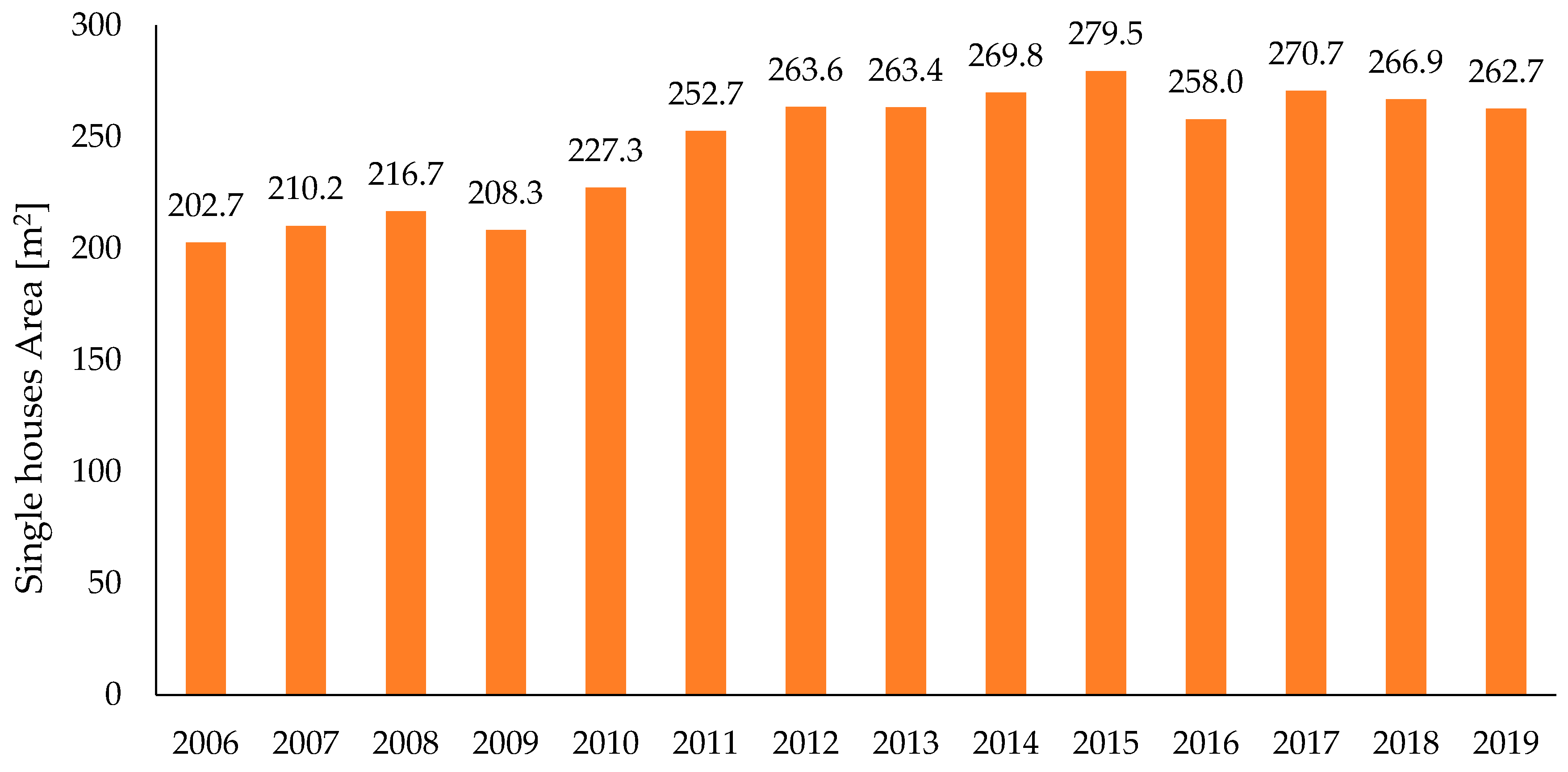
Figure 2 presents the trend of the average area per single house up to the year 2019. It can be seen that although the single housing units were higher between 2006 and 2010 than after, the average area per single house was then smaller than now. This could potentially be explained through the status of the economic stability of Cyprus, but it is beyond the scope of this study to further examine this. As of the year 2012, the average area per single house was between 260 m2 and 270 m2, with an average of 266 m2, one of the highest average areas per dwelling in the European Union [37], with an average household size of 2.7 people living in the same dwelling.

2.1. Typical Construction with Heating and Cooling Loads in Cyprus

Heating and cooling loads depend primarily on the climate of the area. The climate in Cyprus is characterized as intense Mediterranean with a long dry summer of high temperatures (that can reach 40 °C or higher) between mid-May to mid-September. Mild winter is noticeable from November to mid-March, between short autumn and spring seasons with rapid weather changes. The Cyprus Energy Service, for calculations reasons, has separated Cyprus into four climate zones: the coastal zone, the inland zone, the semi-mountains zone (up to 600 m altitude), and the maintains zone (over 600 m altitude) [38].
The impact of the Energy Performance Building Derivative (EPBD) EU derivative 2010/31/EU has caused the typical masonry construction in Cyprus to change towards an improved thermal insulation for the dwellings. A typical masonry, roof, and floor construction before and after the 2010/31/EU was presented by Fokaides et al. [39]. In the past, a typical external wall construction was comprised by a 200 mm brick and 25 mm plaster on each face, while with the new legislation two constructions can be found, with the use of perforated thermal brick and polystyrene as an insulating material (see Table 2 below).
A residential building with an area of 190 m2, in moderate climate, was used in the study of Christodoulides el al. [40], taking heating and cooling loads from Pouloupatis et al. [41] and choosing a heat pump that matches the specific characteristics with its variable pump capacity over power input [42]. This specific case, although an existing house and therefore a realistic scenario, does not cover the scenario of any new buildings with nZEB characteristics or the new “trend” of multi-storage/multi-family buildings.
Although the nZEB construction would be a mandatory requirement, it comes with a high initial construction cost. Several incentives were endorsed from most EU countries, for encouragement to an upgrade of the current buildings into high energy efficient constructions. Serghides et al. [43] have presented an investigation for converting an old single residential building into a nZEB with different scenarios in Cyprus. The results demonstrated that a roof insulation is the most cost-effective measurement, with a reported payback period of less than 2 years. The overall initial investment to a nZEB is noted at €9250 with a payback period of 7–8 years. Similar findings were observed in Greece by Alexandri and Androutsopoulos [44] when investigating the payback period of transforming an existing typical dwelling into a nZEB. Different materials and techniques were considered by the authors with suggestions on the most effective selections. Payback periods as low as 3 years are reported by the authors. An affordability assessment of Energy-Efficient Building Construction in Italy was addressed by Manganelli et al. [45] with a different approach. The authors have viewed this investment from the angle of an entrepreneur in the building sector rather than the owners’ side. The investigated cases have shown that retrofitting an existing building (increasing its energy efficiency) does not provide any benefits in the property value, which is in contrast with newly built buildings.

2.2. Selected Dwelling with Tyical Load for a nZEB

The selected case scenario here is a residential building in Lefkosia, Cyprus (Zone 2—Low mainland area). The masonry and the roof of the building are in accordance with the nZEB characteristics (as described in Table 2) with U values of 0.318 and 0.274, respectively. The area of the residential building was chosen as 260 m2, based on the single-houses trend discussed earlier in the section, and is occupied by a family of four. The residential building was separated into seven zones, consisting of three bedrooms, a kitchen, a living room, a bathroom, and a dining room. The heating and cooling loads of the building were calculated using the TRNSYS software and, specifically, with type 56—Multi-Zone building module. Figure 3 presents the heating (positive values) and cooling (negative values) loads of the investigated residential building. The peak heating load is estimated at 2.99 kW (i.e., 11.51 W m−2 for the 260 m2 residential building under investigation), whereas the peak cooling load is at 7.22 kW (i.e., 27.78 W m−2 for the 260 m2 residential building under investigation). It is clearly a higher cooling demand area with a total of 2150 kWh of heating load and a 11,600 kWh of cooling load. The higher demand months are February for winter season, with 712 kWh heat demand, and July for summer season, with 2882 kWh cooling demand.

3. Computational Modeling

To examine a GHE system, one can perform either physical experiments or computational investigations. In general, the sheer experimental set-up and testing of a GHE is expensive and time-consuming, therefore a computational investigation is preferable. Here, a numerical model using the COMSOL Multiphysics software based on the convection–diffusion equation is introduced. The three-dimensional conservation of the transient heat equation for an incompressible fluid is used:
ρ c p T t + ρ c p u · T + q = Q
where ρ is the density, c p is the specific heat capacity at constant pressure, T is the temperature, t is the time, u is the velocity, Q is the heat source, and q comes from the Fourier’s law of heat conduction. The second term, which includes velocity, is only referring to the domain where groundwater flow is present and does not apply to the rest of the domains.
Depending on the case, the three-dimensional model consists of the pipe domain, the reinforced concrete (either foundation pile of foundation bed) and the ground domain. Modeling and simulation of full-scale geometries for the GHEs can be challenging, as there is a high scale difference between the depth (the z-axis) and the borehole and pipe diameter (x- and y-axes). Due to the high aspect ratio (i.e., the high scale difference between two dimensions as discussed above), meshing the model with equilateral cells will require high computational time and memory.
Existent computational methods could overcome this issue by either applying a coordinate scaling system [29] or by applying parallel computational 1D running with a simplified version (see Equation (2)) on the pipes and Equation (1) on the rest of the system:
ρ A c p T t + ρ A c p u e t · t T = t · ( A k t T ) + 1 2 f D ρ A d h | u | u 2 + Q w a l l
where A is the area of the pipe, u e t is the tangential velocity, f D is the Darcy’s friction factor based on Churchill friction model, and d h is the diameter of the pipe. Q w a l l can be described with the heat conduction equation:
Q w a l l = ( h p Z ) e f f ( T p i p e s T f l u i d )
where T p i p e s is the temperature at the pipe wall, T f l u i d is the fluid temperature in the pipes, ( h p Z ) e f f is the heat transfer coefficient, and Z is the wall perimeter of the pipes.
The following set of heat equations are used to evaluate the input heat on the GHE,
Q = m ˙ c p Δ T ,   Q c o n d = Q e v a p + P c o m p ,   COP = Q c o n d P c o m p ,   Q e v a p = Q c o n d ( 1 1 COP )
where m ˙ is the mass flow rate, Δ T is the temperature difference between the outlet ( T o u t l e t ) and the inlet temperatures ( T i n l e t ) of the GHE, Q c o n d is the heat of the condenser, Q e v a p is the heat of the evaporator, P c o m p is the input work from the compressor, and COP is the Coefficient of Performance. The geometry models were constructed using the built-in environment of COMSOL Multiphysics with two different foundation types constructed.

3.1. Energy Pile

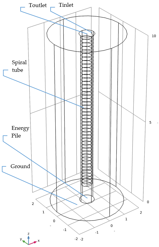
Figure 4 illustrates the geometry of the model serving as a study case, where the spiral coil can be observed as a line in a 3D environment. As the computational processing power and memory are limited, one has to perform a computational investigation on different total mesh elements and different time-dependent solutions. By focusing on a less dense mesh (fewer mesh elements), the quality of the results is altered; therefore, a combination of high-quality mesh cells with denser mesh on the study area is used to lower the computational time and memory. The configuration of the energy pile and the dimensional characteristics are defined in Table 3.

3.2. Foundation Bed GHE

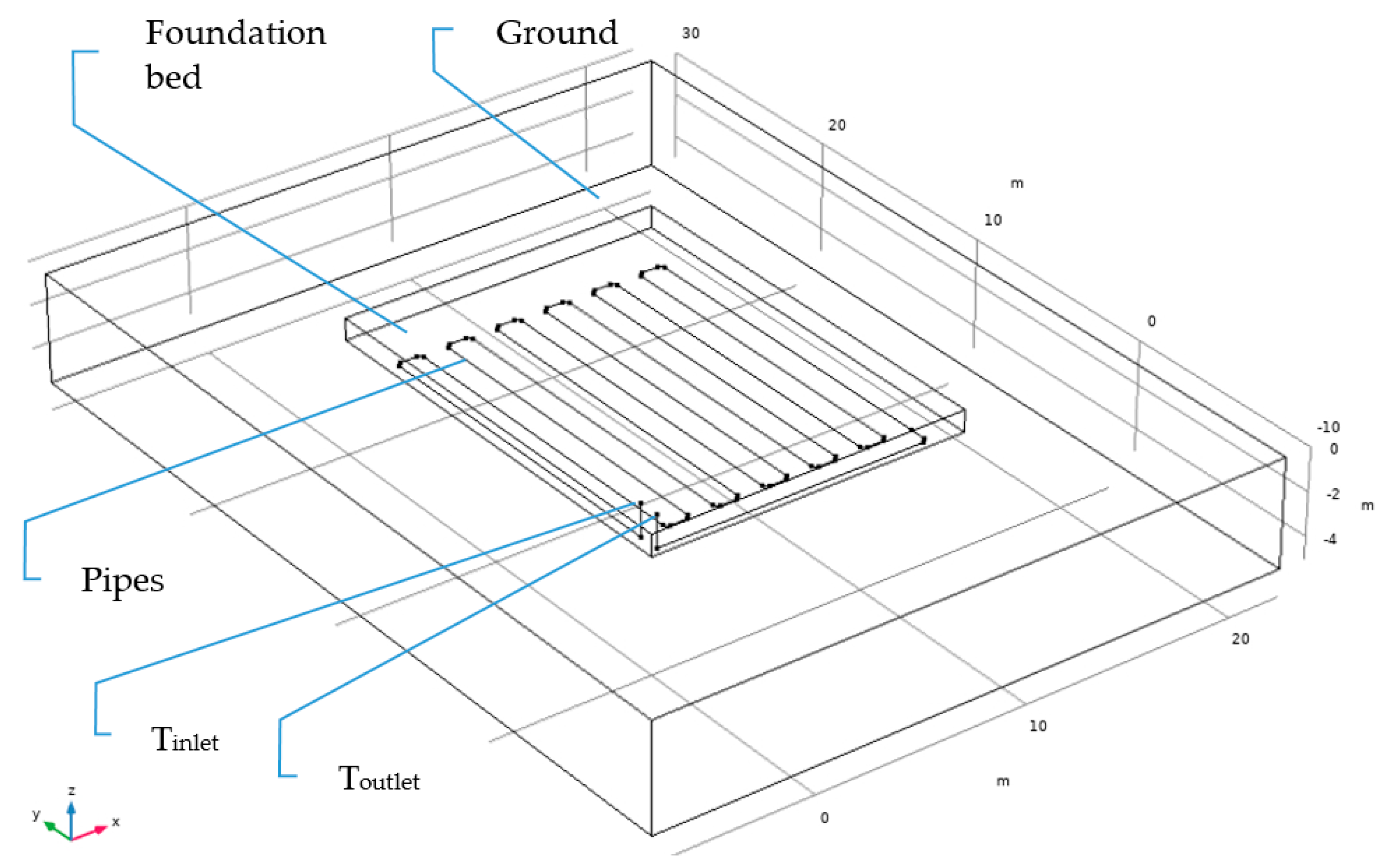
Besides the foundation pile, the most commonly used foundation element is the foundation bed, which can also be converted into a hybrid system and perform as a GHE. In almost all dwellings in Cyprus there is a foundation bed present, therefore making it an ideal element for conversion into a hybrid GHE system. As the foundation bed is not primarily designed as a GHE, it must be constructed according to the geometry and the required strength characteristics set by the civil engineers. A further discussion of those effects of a hybrid foundation bed system was performed by Aresti et al. [46]. Figure 5 demonstrates the geometry of such system. The material used is kept the same as in the case of the Energy Pile. The configuration of the foundation bed and the dimensional characteristics are defined in Table 4.

3.3. Computational Verification and Validation

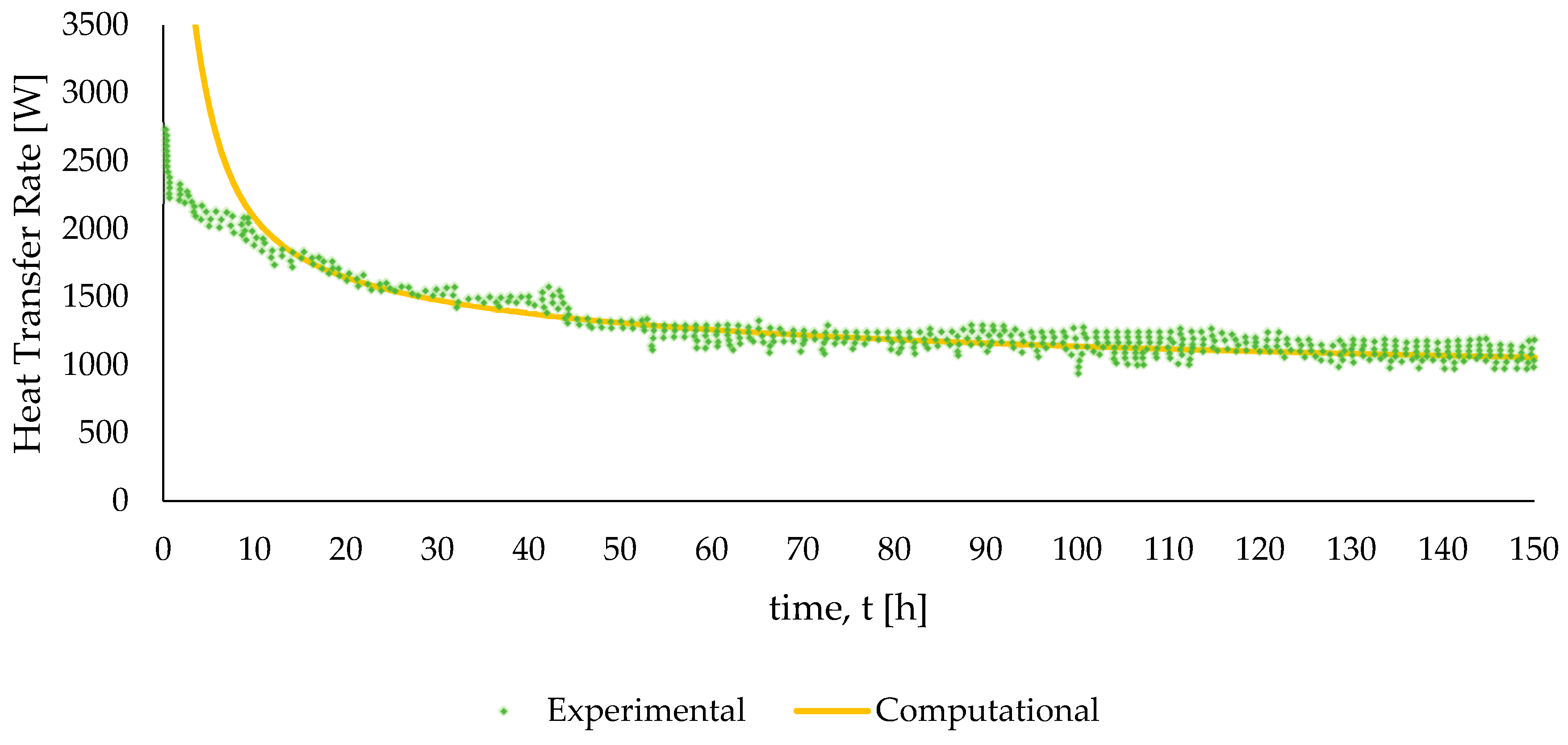
In order to perform a computational investigation, it is of importance to provide a verification and a validation model with experimental results. COMSOL Multiphysics was used for a three-dimensional model consisting of the spiral pipe domain, the grout domain (borehole), and the ground domain with its sublayers. The same computational model with its boundary conditions for the energy pile of Section 3.1 is adapted to the actual parameters taken from experimental data by Dehghan [47]. The model constructed is based on the convection–diffusion equation (described by Equations (1) and (2)), with the following parameters/conditions: pipe radius of 0.014 m, pipe thickness 0.003 m, borehole depth 4 m, borehole diameter 0.45 m, spiral pitch 0.1 m, volumetric flow rate 15 L/min, initial ground temperature 18 °C, and the inlet temperature as fixed at 50.7 °C. Experimental data were obtained using a Thermal Response Test (TRT), a conventional test for determining the ground thermal characteristics [48]. Figure 6 shows the validation of the model by comparing experimental and computational data. The overall validation indicates a very good agreement between the experimental and computational data, excepting the first 10 h of the model run; this can be due to the lack of detailed information from the experimental data, as only average values were provided. All in all, it is safe to assume that the computational model is accurate enough to predict the outcome of the systems under investigation.

4. Computational Results and Discussion

The computational models could be then modified to incorporate a theoretical case scenario of a foundation pile GHE and a foundation bed GHE installed in a residential building in Cyprus for moderate climate conditions. The validated models are subsequently adapted to match the Mediterranean conditions in Cyprus.

4.1. Energy Piles

The energy pile model (seen in Figure 4) consists of a 10 m depth foundation pile with reinforced concrete, a 0.8 m pile diameter, a 9 m depth spiral HDPE (High Density Polyethylene) coil contained in the foundation pile, and an overall domain of a 4 m diameter. Note that a similar configuration was installed at the new public university library in Lemesos, Cyprus, where the spiral coil GHE was incorporated in a well.
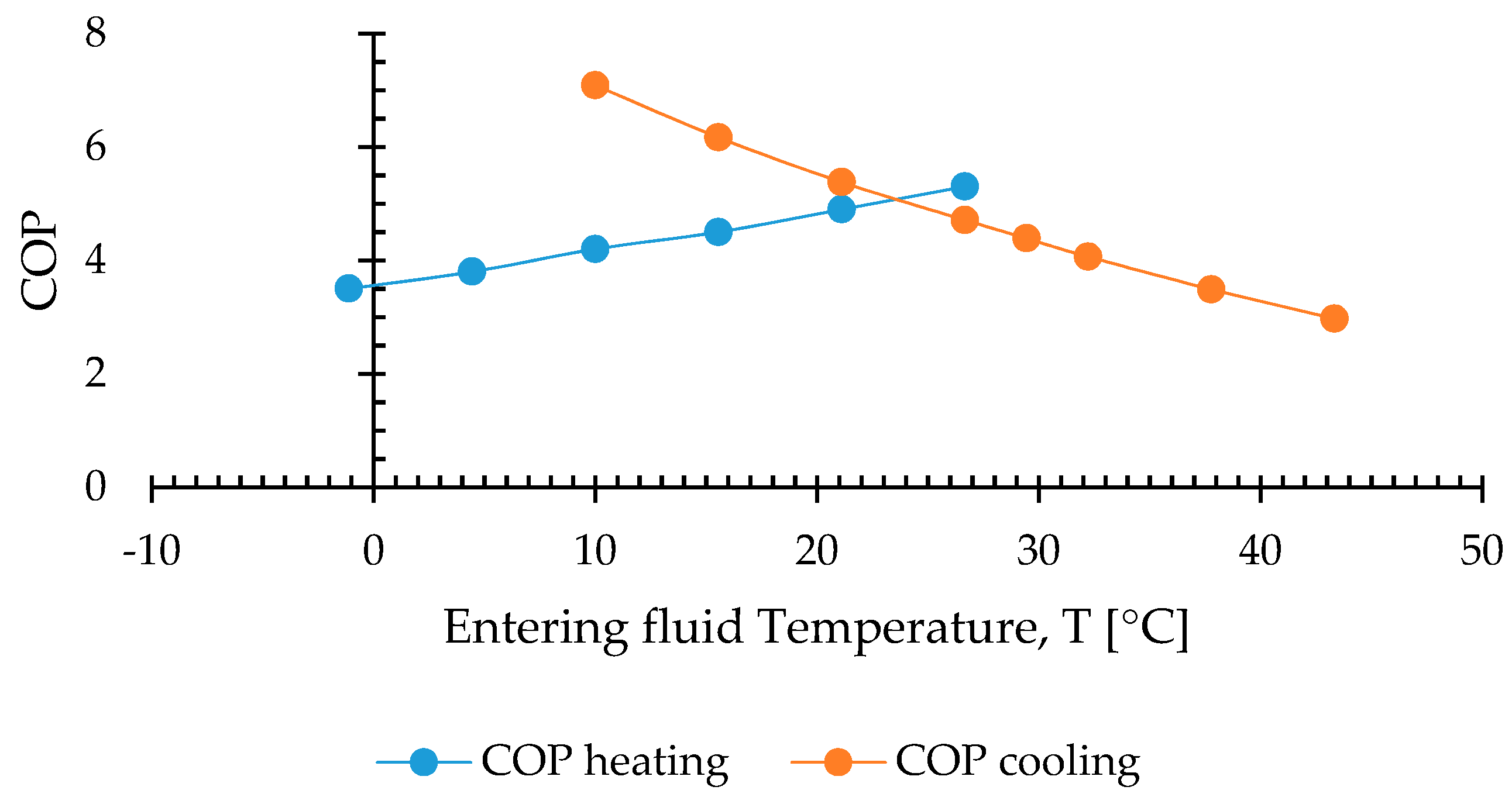
In order to obtain more accurate and realistic results, experimental ground temperature data were considered, where the temperature below a depth of 7 m is constant at 22.7 °C [28,49]. The same temperatures are observed in a similar case in Lemesos by Florides et al. [50]. Additionally, based on the current calculated loads, a GSHP was selected (LM series by BOSCH) to calculate the COP of the system. The COP varies depending on the entering fluid temperature, as shown in Figure 7.
The equation of the undistributed ground temperature is used as input for the initial temperature in the computational model as presented by Stylianou et al. [28]. The case of summer was examined for the month of July, and of winter for the month of February. This selection is based on the fact that the highest loads are observed during those months. Furthermore, the ground characteristics of the case study in Lefkosia are considered [51]. The ground examined consisted of marl, chalk, and gravel, with the complete model material properties described in Table 5.
A foundation pile system does, however, contain more than one pile, and this number is depended on the study of the civil engineer. For this specific case, four energy piles were incorporated into the system with all four working in parallel. The computational results of an energy piles system using COMSOL Multiphysics for the months of February and July are presented in Figure 8 and Figure 9. The results of the outlet temperature are used to calculate the COP of the heat pump, where the lower the outlet temperature of the coil (entering the pump), the higher the pump efficiency [42].
It can be observed in Figure 8 that the operating outlet temperature is between 18 °C and 21 °C, providing a high COP on the highest load month of winter at 4.8. The COP is, naturally, fluctuating depending on the required load, with a minimum COP of 4.7. It should be noted that, although the system is performing ideally, the peak load is at 3 kW and the total load of the month is only at 712 kWh. This change in the load can be observed in the summer months, and more specifically in the month of July, where a higher peak load is required, 7.22 kW, and a total month load of 2882 kWh. This is essentially 4 times the load of the highest winter month, February.
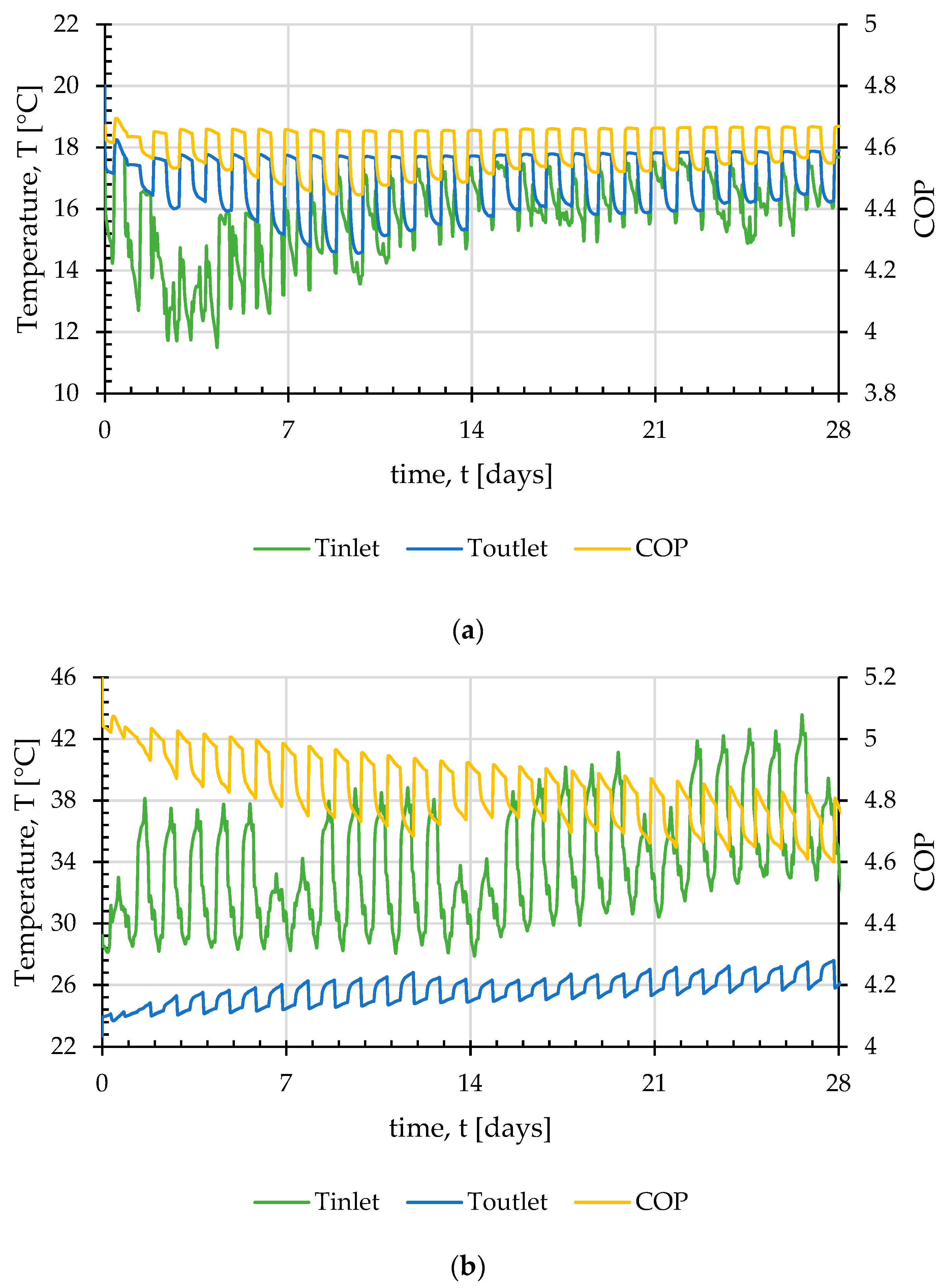
The results of the energy piles system with the summer month load are presented in Figure 9. During the initial test with the system of four energy piles, it can be seen that the temperature was nearly steady up to the 16th day, but with the higher load demand in the end of the month, the outlet temperature rose up to 30 °C. Convectional outlet operating temperature ranges between 26 °C and 28 °C, as suggested by an existing convectional GHSP system in the public university library in Lemesos. Therefore, the 4-energy pile system, although providing a higher outlet temperature, maintains a high COP (4.4–4.7). Further examination was carried out by raising the number of energy piles in the system to investigate whether the additional piles could sustain the higher summer load. An increase of the piles to 6 or 8 does result in, as expected, a reduction in the outlet temperature and higher COP values (Figure 10). This is however a decision that is not made because of the buildings’ HVAC requirements but because of structural reasons. Therefore, if more foundation piles are used in the system, the GSHP system could maintain a higher COP values and higher loads.
Regarding the effect of parameters, out of several parameters, as mentioned above (e.g., borehole diameter, center-to-center distance, pipe diameter, etc.), the spiral pitch is one that does not depend on the geo-structure. Decreasing the spiral pitch yields an increase in the outlet temperature of the pipe and a reduction in the heat transfer rate, as recorded by Carotenuto et al. [17] and Park et al. [25,26].

4.2. Foundation Bed

In the case where the foundation piles are absent (not included in the design of the building), the foundation bed could eventually be used as a GHE. The foundation bed is a most common element in the residential buildings in Cyprus. The same heating and cooling loads and the same ground characteristics as for the energy pile system are used for the computational investigation of the foundation bed as a GHE. A major difference in this case is the very shallow depth of the system (1 m), making it liable to the ambient daily temperature. The ambient temperature was therefore applied as a boundary condition on the top surface of the ground domain with temperature data from the year 2019.
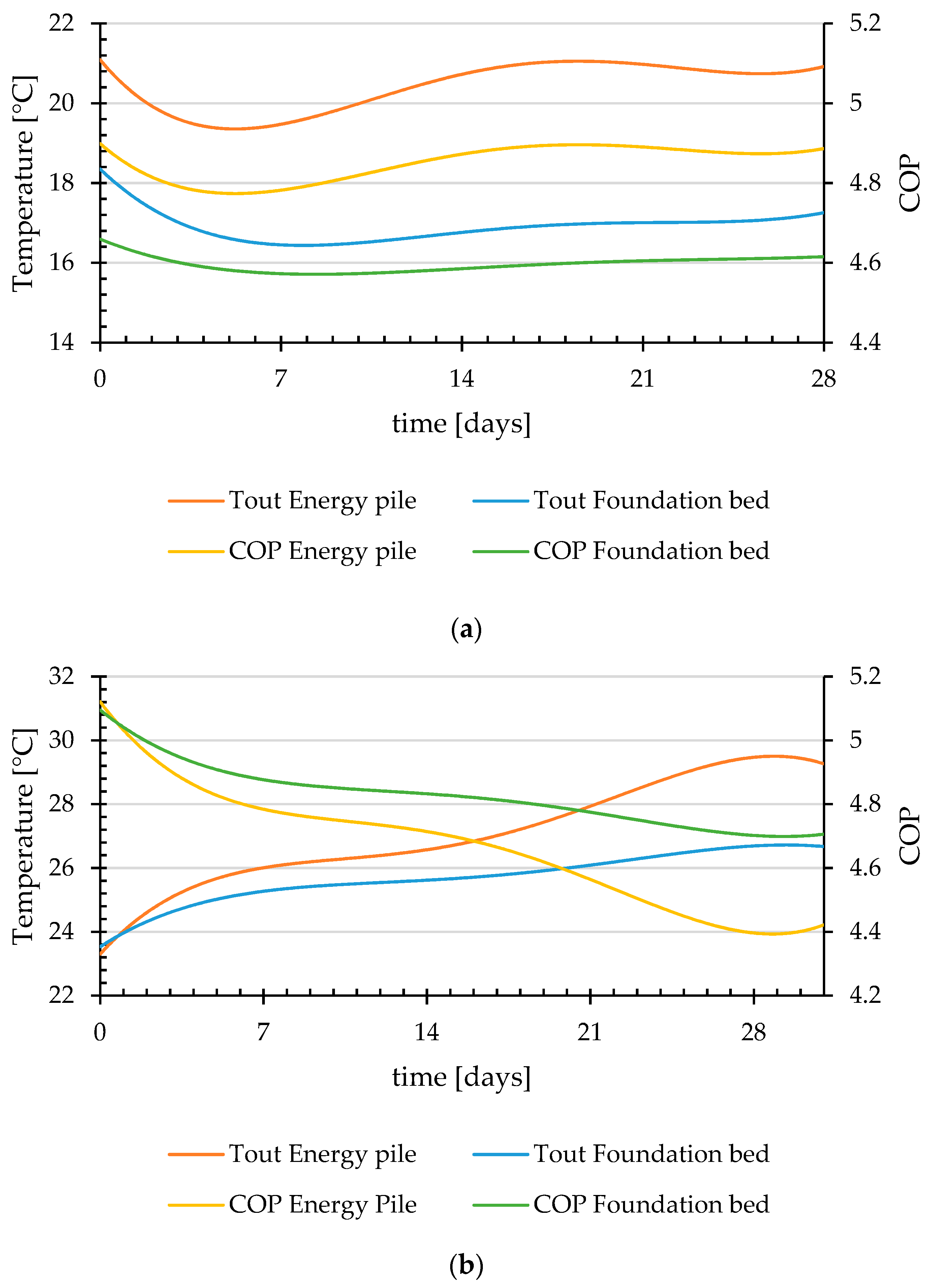
The results of the outlet temperature and COP of the foundation bed as a GHE are presented in Figure 10. In both cases, winter (February) and summer (July), the system appears to have a steady performance for the outlet temperature, providing a high COP of 4.6 during winter and 4.8 during summer.
An aspect that should be examined is the increase in the temperature of the surface in contact with the indoor space (on the house floor). An increase in the house contact surface temperature would have a negative impact of the cooling loads, as the heating energy rejected under the house would return through the foundation bed. This could be easily addressed with an insulation on the floor of the house, the same method applied on the roof.
A comparison on the performance of the foundation bed system with the energy piles system is presented in Figure 11 for both summer and winter conditions. The foundation bed as a GHE is observed to have a steady performance, something very desirable in a system. This however comes in a lower performance compared to the energy piles system, where higher COP values are provided during the winter, albeit failing to deliver the same efficiency during the summer.
This comparison however is not unbiased since one system (foundation bed) can be characterized as a horizontal system with larger area, and the other (energy piles) as a vertical system with limited depth. In reality, the main interest is not which system would perform best, but whether the systems could be used as hybrid element (GHE and buildings foundation) in a residential building, according to the applied construction. In this respect, it is safe to say that both systems accomplish worthy performance as GHEs in a GSHP system.

5. Economic Evaluation

Every energy system, even a RES, is only acceptable and widely applicable when the system is viable and economically beneficial for the user/investor. It is therefore advisable to examine not only the performance of a GSHP system, but also its economic sustainability and its optimal performance cost. Even though GSHPs have higher performance in comparison to the Air Source Heat Pumps (ASHPs), the system’s high initial costs and long payback period have made it unattractive as an investment [40,52]. It was reported by several authors that greater performance of a GSHP system could be achieved using spiral coil/energy piles in comparison with convectional ASHP systems [13,25,53,54,55].
Yoon et al. [13] compared three different configurations, W type, 3U type and spiral coil type, for an energy pile system installation in terms of thermal characteristics and costs. The energy piles were considered to have the same load of 57 kW, the same depth of 13.5 m, and the same COP of 4.7. The results indicated that the coil type configuration required the least amount of piles to be installed, but at the same time the highest construction cost, approximately three times the cost of the W type heat exchanger. The authors mentioned that the 3U-tube and W type heat exchangers increase the number of piles by 20–30% in comparison with the spiral coil heat exchanger pile. It is however worth stating that the cost of the GHE is only 1% of the total cost of the construction.
To determine the optimal coil pitch, the long-term heat exchanger rate and the economic feasibility were considered by Park et al. [26]. The authors varied the coil pitch as 100, 200, 350. and 500 mm, but kept the pile depth steady, therefore decreasing the pipe length (475 m, 240 m, 160 m, and 101 m respectively). The authors found that the heat transfer rate of the pile increased with the reduction of the coil pitch, but at the same time the construction cost ratio (material cost and the installation) increased. The authors also accounted for the operating cost by considering an 8-h daily operation time with 3 months heating operation and 3 months cooling operation. This resulted in payback periods of 2.00, 1.29, 1.14, and 1.09 years for the different coil pitches of 100, 200, 350, and 500 mm, respectively. Therefore, although the best configuration in terms of heat transfer rate is the minimum coil pitch (100 mm), in terms of cost benefit it returns the highest payback period. The authors also noted that the optimum coil pitch should be considered with the ground conditions and the operation cost taken in account.
The initial cost comparison of two different GHEs, namely the double U-tube and the spiral tube, were investigated and presented by Suzuki et al. [56], in accordance to the heat exchanging capacity. The authors studied depths of 10 m and 20 m for spiral GHEs and a 70 m for the double U-tube. The results indicated a reduction of 30% in the initial cost per collected quantity of heat when the spiral tube was used over the double U-tube. Another economic study under cooling dominated condition was presented by Akroush et al. [57]. The authors presented the Present Value and reported a 13-year Simple Payback Period by comparing an ASHP system with a GSHP system. This value, although less than the estimated lifespan of a GSHP (estimated at 25 years), did not make it attractive as an investment.
An economic evaluation of the sustainability of a typical GSHP system under moderate climate in Cyprus was explored and discussed by Michopoulos et al. [58]. The authors explored different dwelling cases (single-family building and multi-family building) in five different areas of Cyprus (Nicosia (Lefkosia), Larnaca, Limassol (Lemesos), Paphos, and Saittas). European standards were used for the methodology to calculate the Net Present Value (NPV) with an economic lifetime of 15 years. The authors presented the results in comparison with an ASHP system with either LPG or oil-fired boiler and stated that in the case of a single house, a GSHP system is only economically profitable for the area of Saittas, the area with the highest heating demand. In the second case of a multi-family building, Saittas area was again a very favorable solution for GSHPs as were the cities of Nicosia and Larnaca. Similar findings were observed by Christodoulides et al. [40], who studied a single family house with specific heating and cooling loads, with a selected case specific heap pump COP values. The authors presented different methods to evaluate the economic benefits of a GSHP system that resulted in long payback periods for all cases, making the GSHP system not economically favorable.

Economic Evaluation of a Residential Building as a GHE Results

The above-mentioned cases and related literature point to the initial cost as the main drawback of these (GSHPs) highly efficient systems. Therefore, the conversion to a hybrid system of an existing element in the house, such as the foundation, would have a significant impact in lowering the initial costs. In order to verify this rationale, the initial and running costs of the foundation GSHP system studied in the current paper were compared with a typical ASHP system.
Several methods could be used to evaluate the economic benefits of the system, such as the Present Worth (PW), the Annual Worth (AW), the Internal Rate of Return (IRR), the External Rate of Return (ERR), the Simple Payback Period (SPP), the Discounted Payback Period (DPP), the Annualised Life Cycle Cost (ALCC) method, the Levelized Cost of Energy (LCOE) [29], and the equivalent Total Annual Economic Cost (TAEC), with a brief explanation and application of the methods provided in the literature [59,60,61,62]. To simplify the study, only the difference in the costs of the two systems was used in the calculations. The cost breakdown of the systems is described in Table 6. As it can be seen, the costs related to grout filling and for borehole extraction are not included, as the building foundation would be constructed in any case, therefore no costs are added. The cost of the heat pumps (HPs) was estimated based on the local market (as of year 2020) at €8500 for a high-efficiency ASHP, €4500 for a low-efficiency ASHP, and at €6500 for a GSHP.
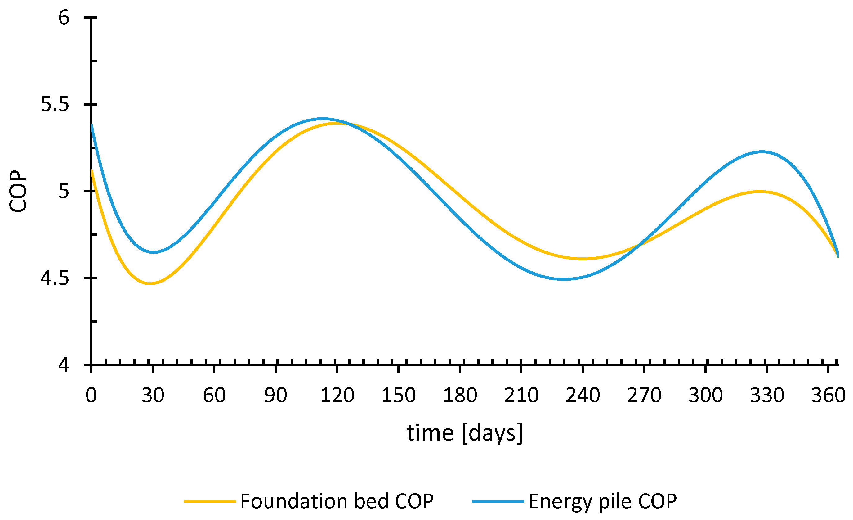
Furthermore, the cost difference was used as an input to evaluate the economic benefits of the system. The simple methods for computing the payback period require to equal the inflow and outflow cash per year, as described by the SPP and DPP [40]. The inflation of the electricity price, the maintenance and the discounting future cash flow [63] are incorporated, and the current household electricity price in Cyprus is considered as 0.19€/kWh. The COP values are estimated per hour for each month for one year and are presented in a polynomial form of order of 6 in Figure 12. Both systems exhibit similar behavior, where it can be seen that in the high load months (as in the case of February and July) the COP values drop, and higher values are observed in the less demanding months (April and November). The lifespan of the HPs was assumed at 12 years for both the ASHPs and the GSHPs. Table 7 describes the average COP of each system per month and the total input electrical energy required per year for the modeled typical residential building. The overall yearly average COP for the foundation bed is 4.90, with an average of 4.73 during the winter and 5.00 during the summer. On the other hand, the energy pile system exhibits a higher COP, compared to the foundation bed system during winter with values of 4.84, and a lower one during the summer mode with a value of 4.97. An overall yearly average of 4.94 is estimated.
The GSHP systems are assumed to replace an ASHP system with either high or low efficiency. The highly efficient ASHP system is assumed to have a COP of 3.0 during heating mode (winter) and 3.7 during cooling mode (summer), whereas the low efficiency ASHP system is assumed to have a COP of 3.0 and 2.5 for summer and winter, respectively. By considering the heating and cooling loads of the residential building under investigation (2150 kWh in winter and 11,600 kWh in summer), the input electrical power required is 3852 kWh and 4727 kWh for the high- and low-efficient ASHP respectively. The difference between the required consumption of the ASHP system from the GSHP system characterizes the savings achieved per year. Savings of 1003 kWh and 967 kWh are estimated for the foundation bed and the energy pile GSHP systems respectively, compared to a high-efficient ASHP system. Savings of 1878 kWh and 1842 kWh are estimated for the foundation bed and energy pile GSHP system respectively, compared to a low-efficiency ASHP system.
Table 8 presents the energy savings as equivalent financial savings in order to allow one to investigate the systems as an investment. The initial cost to compensate are the values from Table 6, whereas the total savings per year column assumes the electricity savings with the current electricity unit price, and the savings for maintenance and end-of-life heat pump replacement. Two methods are presented, namely, the SPP and the DPP, with three further variations. The SPP has been varied with a 2% increase of the electricity price, whereas the DPP has been varied with a 2% and 5% electricity price inflation.
By examining the results (seen in Table 8) for the SPP and the DPP, it can be clearly seen that the investment, and risk, is worth taking. A maximum SPP of 7.41 years was observed on the Energy Pile system with the worst overall case noticed at a 2%-DPP of 8.10 years. The SPP and DPP values of the conversion foundation bed into a GHE are even lower, with less than 8 years, in comparison with a low-cost low-efficiency ASHP and less than 2 years with an expensive high-efficiency ASHP. These results come in contrast with previous studies comparing GSHP systems with ASHP or other solutions [40,59,64]. The last column of Table 8 shows the yearly cash flow return rate for the worst-case scenario for each system, which in all cases exceeds 8%, a figure pointing to a good investment.
The results above assume that the performance of the system will remain steady throughout the lifespan of the system. Although the loads seem unbalanced (higher cooling loads compared to heating loads), there are two months with insignificant loads (namely, March and November), which can be considered as buffer months providing time for the ground to return to the natural undistributed temperature. However, with constant heat injection to the ground, the ground temperature might increase, thereby reducing the COP values during the summer mode. This ground temperature increase has been observed in long-term simulations [65] and experiments [66], where depending on the case, the COP can be dramatically reduced (as far as 50% in a 15 year operation time [65]). By examining the current case study, with the lifespan of the GSHP set to 12 years and a COP reduction of 25% assumed (an extreme figure for the current case study), there will still be a significantly low SPP (7.95 years in the worst case) and DPP (8.75 years in the worst case). This is because the COP reduction is achieved gradually, which means only a 2% reduction per year, which will have an insignificant impact on the system and the investment. Even if one assumes a constant ASHP COP throughout the lifespan, the GSHP system will remain a sustainable investment if its COP is not reduced by more than 25%.
The described integration of the buildings foundations can undeniably lower the initial cost of the systems, providing a viable solution into a “greener” future. This green solution could be further explored through an environmental-impact comparison with existing GHE systems [67].

6. Conclusions

The high initial cost of GSHP systems in comparison to the convectional ASHP systems has steered researchers and engineers to convert existing dwelling elements into GHEs. Such hybrid elements, as addressed in the current study, can be the foundation bed and the foundation piles. The housing trend in Cyprus has been examined and a typical average residential building with ZEBs characteristics was theoretically investigated. With the use of the TRNSYS software the heating and cooling loads were calculated in order to evaluate whether the buildings foundations could positively respond to the specific loads by maintaining a steady temperature.
A COMSOL Multiphysics computational model for both the energy pile system and the foundation bed system was constructed and simulated taking in account the site ground temperature characteristics and the local ambient temperature. The inlet and outlet temperatures were calculated hourly (based on the provided loads) for the two months of highest demand of summer (July) and winter (February). The obtained results have shown that both systems provide high COPs and nearly steady conditions, with COP values varying between 4.4 and 4.8. A further investigation on a yearly simulation has shown that the lowest COP values achieved by the systems were 4.60 and 4.51 for the foundation bed and the energy piles system, respectively. The two systems exhibit similar performance, with average heating (winter) and cooling (summer) COP values estimated at 4.73 and 5.00 for the foundation bed GSHP system, and 4.84 and 4.97 for the energy pile GSHP system.
Finally, an economic evaluation of both systems has been performed using the simple SPP and DPP methods. The monthly loads and average monthly COP values of each system as well as the lifespan and the cost of the heat pump replacement were considered. The electricity price inflation was also considered for two scenarios, with a 2% inflation and an “extreme” 5% yearly inflation. Both systems have been demonstrated to be attractive investments as they exhibit short payback periods. Specifically, the best-case scenario for the energy pile systems is estimated to be 2.04 years and 1.93 years for the foundation bed system, whereas the “worst” cases are 6.97 years and 6.85, respectively. Regarding cash flow return, the worst-case scenario for all systems, results in a very satisfactory figure exceeding 8%.
Therefore, the above-mentioned hybrid elements may offer a solution towards overcoming the barriers of high initial investments and long payback periods that have kept unpopular the GSHP systems hiding during the past years.

Author Contributions

Conceptualization, L.A. and P.C.; methodology, L.A.; software, L.A. and G.P.P.; validation, L.A.; formal analysis, L.A., P.C., and G.F.; investigation, L.A.; writing—original draft preparation, L.A.; writing—review and editing, L.A., G.F., and P.C.; supervision, P.C.; All authors have read and agreed to the published version of the manuscript.

Funding

This research received no external funding.

Conflicts of Interest

The authors declare no conflict of interest.

Appendix A

Table A1. Conversion factors for different types of fuels to primary energy units (PEU).
FuelCO2 Emissions
(kgCO2/kWh)
Primary Energy
(kWh)
Diesel oil0.2661.1
Grid supplied electricity0.7942.7
Grid displaced electricity0.7942.7
LPG0.2491.1
Biomass0.0251.1

References

  1. EuroStat. Energy Consumption and Use by Household. Available online: https://ec.europa.eu/eurostat/web/products-eurostat-news/-/DDN-20190620-1 (accessed on 10 February 2019).
  2. EU Parliament. Directive 2010/31/Eu of the European Parliament and of the Council of 19 May 2010 on the Energy Performance of Buildings; EU Parliament: Brussels, Belgium, 2010. [Google Scholar]
  3. Lund, J.W.; Toth, A.N. Direct utilization of geothermal energy 2020 worldwide review. Geothermics 2020, 60, 66–93. [Google Scholar] [CrossRef]
  4. Aresti, L.; Christodoulides, P.; Florides, G. A review of the design aspects of ground heat exchangers. Renew. Sustain. Energy Rev. 2018, 92, 757–773. [Google Scholar] [CrossRef]
  5. Bezyan, B.; Porkhial, S.; Mehrizi, A.A. 3-D simulation of heat transfer rate in geothermal pile-foundation heat exchangers with spiral pipe configuration. Appl. Therm. Eng. 2015, 87, 655–668. [Google Scholar] [CrossRef]
  6. Zhao, Q.; Chen, B.; Liu, F. Study on the thermal performance of several types of energy pile ground heat exchangers: U-shaped, W-shaped and spiral-shaped. Energy Build. 2016, 133, 335–344. [Google Scholar] [CrossRef]
  7. Fadejev, J.; Simson, R.; Kurnitski, J.; Haghighat, F. A review on energy piles design, sizing and modelling. Energy 2017, 122, 390–407. [Google Scholar] [CrossRef]
  8. Brandl, H. Thermo-active Ground-Source Structures for Heating and Cooling. Procedia Eng. 2013, 57, 9–18. [Google Scholar] [CrossRef] [Green Version]
  9. De Moel, M.; Bach, P.M.; Bouazza, A.; Singh, R.M.; Sun, J.O. Technological advances and applications of geothermal energy pile foundations and their feasibility in Australia. Renew. Sustain. Energy Rev. 2010, 14, 2683–2696. [Google Scholar] [CrossRef] [Green Version]
  10. Gao, J.; Zhang, X.; Liu, J.; Li, K.; Yang, J. Numerical and experimental assessment of thermal performance of vertical energy piles: An application. Appl. Energy 2008, 85, 901–910. [Google Scholar] [CrossRef]
  11. Gashti, E.H.N.; Uotinen, V.-M.; Kujala, K. Numerical modelling of thermal regimes in steel energy pile foundations: A case study. Energy Build. 2014, 69, 165–174. [Google Scholar] [CrossRef]
  12. Suryatriyastuti, M.; Mroueh, H.; Burlon, S. Understanding the temperature-induced mechanical behaviour of energy pile foundations. Renew. Sustain. Energy Rev. 2012, 16, 3344–3354. [Google Scholar] [CrossRef]
  13. Yoon, S.; Lee, S.-R.; Xue, J.; Zosseder, K.; Go, G.-H.; Park, H. Evaluation of the thermal efficiency and a cost analysis of different types of ground heat exchangers in energy piles. Energy Convers. Manag. 2015, 105, 393–402. [Google Scholar] [CrossRef]
  14. Sterpi, D.; Tomaselli, G.; Angelotti, A. Energy performance of ground heat exchangers embedded in diaphragm walls: Field observations and optimization by numerical modelling. Renew. Energy 2020, 147, 2748–2760. [Google Scholar] [CrossRef] [Green Version]
  15. Loveridge, F. The Thermal Performance of Foundation Piles used as Heat Exchangers in Ground Energy Systems. Ph.D Thesis, University of Southhampton, Southhampton, UK, June 2012. [Google Scholar]
  16. Sani, A.K.; Singh, R.M.; Amis, T.; Cavarretta, I. A review on the performance of geothermal energy pile foundation, its design process and applications. Renew. Sustain. Energy Rev. 2019, 106, 54–78. [Google Scholar] [CrossRef]
  17. Carotenuto, A.; Marotta, P.; Massarotti, N.; Mauro, A.; Normino, G. Energy piles for ground source heat pump applications: Comparison of heat transfer performance for different design and operating parameters. Appl. Therm. Eng. 2017, 124, 1492–1504. [Google Scholar] [CrossRef]
  18. Zarrella, A.; De Carli, M.; Galgaro, A. Thermal performance of two types of energy foundation pile: Helical pipe and triple U-tube. Appl. Therm. Eng. 2013, 61, 301–310. [Google Scholar] [CrossRef]
  19. Zhao, Q.; Liu, F.; Liu, C.; Tian, M.; Chen, B. Influence of spiral pitch on the thermal behaviors of energy piles with spiral-tube heat exchanger. Appl. Therm. Eng. 2017, 125, 1280–1290. [Google Scholar] [CrossRef]
  20. Saeidi, R.; Noorollahi, Y.; Esfahanian, V. Numerical simulation of a novel spiral type ground heat exchanger for enhancing heat transfer performance of geothermal heat pump. Energy Convers. Manag. 2018, 168, 296–307. [Google Scholar] [CrossRef]
  21. Dehghan, B.; Sisman, A.; Aydin, M. Parametric investigation of helical ground heat exchangers for heat pump applications. Energy Build. 2016, 127, 999–1007. [Google Scholar] [CrossRef]
  22. Park, H.; Lee, S.; Yoon, S.; Shin, H.; Lee, D.-S. Case study of heat transfer behavior of helical ground heat exchanger. Energy Build. 2012, 53, 137–144. [Google Scholar] [CrossRef]
  23. Kim, M.-J.; Lee, S.; Yoon, S.; Jeon, J.-S. Evaluation of geometric factors influencing thermal performance of horizontal spiral-coil ground heat exchangers. Appl. Therm. Eng. 2018, 144, 788–796. [Google Scholar] [CrossRef]
  24. Cui, P.; Li, X.; Man, Y.; Fang, Z. Heat transfer analysis of pile geothermal heat exchangers with spiral coils. Appl. Energy 2011, 88, 4113–4119. [Google Scholar] [CrossRef]
  25. Park, S.; Lee, D.; Choi, H.-J.; Jung, K.; Choi, H. Relative constructability and thermal performance of cast-in-place concrete energy pile: Coil-type GHEX (ground heat exchanger). Energy 2015, 81, 56–66. [Google Scholar] [CrossRef]
  26. Park, S.; Lee, S.; Lee, D.; Lee, S.S.; Choi, H. Influence of coil pitch on thermal performance of coil-type cast-in-place energy piles. Energy Build. 2016, 129, 344–356. [Google Scholar] [CrossRef]
  27. Fan, R.; Jiang, Y.; Yao, Y.; Shiming, D.; Ma, Z. A study on the performance of a geothermal heat exchanger under coupled heat conduction and groundwater advection. Energy 2007, 32, 2199–2209. [Google Scholar] [CrossRef]
  28. Stylianou, I.I.; Tassou, S.; Christodoulides, P.; Aresti, L.; Florides, G. Modeling of vertical ground heat exchangers in the presence of groundwater flow and underground temperature gradient. Energy Build. 2019, 192, 15–30. [Google Scholar] [CrossRef]
  29. Aresti, G.A.L.; Florides, P. Christodoulides, “Computational modelling of a ground heat exchanger with groundwater flow. Bulg. Chem. Commun. 2016, 48, 55–63. [Google Scholar]
  30. Huang, G.; Yang, X.; Liu, Y.; Zhuang, C.; Zhang, H.; Lu, J. A novel truncated cone helix energy pile: Modelling and investigations of thermal performance. Energy Build. 2018, 158, 1241–1256. [Google Scholar] [CrossRef]
  31. Mehrizi, A.A.; Porkhial, S.; Bezyan, B.; Lotfizadeh, H. Energy pile foundation simulation for different configurations of ground source heat exchanger. Int. Commun. Heat Mass Transf. 2016, 70, 105–114. [Google Scholar] [CrossRef]
  32. Kayaci, N.; Demir, H. Comparative performance analysis of building foundation Ground heat exchanger. Geothermics 2020, 83, 101710. [Google Scholar] [CrossRef]
  33. Aresti, L.; Christodoulides, P.; Lazari, L.; Florides, G. Computational Investigation on the Effect of Various Parameters of a Spiral Ground Heat Exchanger. In Proceedings of the 12th International Workshop on Applied Modeling & Simulation (WAMS 2019), NUSS Kent Ridge Guild House, Singapore, 30–31 October 2019. [Google Scholar]
  34. Ministry of Commerce Industry and Energy Tourism. 2nd National Plan for Increasing the Number of Nearly Zero-Energy Buildings (NZEBs); European Commission: Athens, Greece, 2017.
  35. Panayiotou, G.P.; A Kalogirou, S.; Florides, G.; Maxoulis, C.; Papadopoulos, A.M.; Neophytou, N.; Fokaides, P.A.; Georgiou, G.; Symeou, A.; Georgakis, G. The characteristics and the energy behaviour of the residential building stock of Cyprus in view of Directive 2002/91/EC. Energy Build. 2010, 42, 2083–2089. [Google Scholar] [CrossRef]
  36. CYSTAT. Construction and Housing Statistics; Statistical Service of the Republic of Cyprus: Nicosia, Cyprus, 2016.
  37. European Committee. Eurostat Database; European Commission: Brussels, Belgium, 2016. [Google Scholar]
  38. Cyprus Energy Service. Thermal Insulation Guide, 2nd ed.; Ministry of Energy Commerce Industry and Tourism: Nicosia, Cyprus, 2009.
  39. Fokaides, P.A.; Christoforou, E.A.; Kalogirou, S.A. Legislation driven scenarios based on recent construction advancements towards the achievement of nearly zero energy dwellings in the southern European country of Cyprus. Energy 2014, 66, 588–597. [Google Scholar] [CrossRef]
  40. Christodoulides, P.; Aresti, L.; Florides, G. Air-conditioning of a typical house in moderate climates with Ground Source Heat Pumps and cost comparison with Air Source Heat Pumps. Appl. Therm. Eng. 2019, 158, 113772. [Google Scholar] [CrossRef]
  41. Pouloupatis, P.D. Determination of the Thermal Characteristics of the Ground in Cyprus and Their Effect on Ground Heat; Brunel University: London, UK, 2014. [Google Scholar]
  42. Pouloupatis, P.; Tassou, S.; Christodoulides, P.; Florides, G. Parametric analysis of the factors affecting the efficiency of ground heat exchangers and design application aspects in Cyprus. Renew. Energy 2017, 103, 721–728. [Google Scholar] [CrossRef]
  43. Serghides, D.K.; Dimitriou, S.; Katafygiotou, M.C.; Michaelidou, M. Energy Efficient Refurbishment towards Nearly Zero Energy Houses, for the Mediterranean Region. Energy Procedia 2015, 83, 533–543. [Google Scholar] [CrossRef] [Green Version]
  44. Alexandri, E.; Androutsopoulos, A. Energy Upgrade of Existing Dwellings in Greece; Embodied Energy Issues. Procedia Environ. Sci. 2017, 38, 196–203. [Google Scholar] [CrossRef]
  45. Manganelli, B.; Morano, P.; Tajani, F.; Salvo, F. Affordability Assessment of Energy-Efficient Building Construction in Italy. Sustainability 2019, 11, 249. [Google Scholar] [CrossRef] [Green Version]
  46. Aresti, L.; Christodoulides, P.; Panayiotou, G.P.; Florides, G. The Potential of Utilizing Buildings’ Foundations as Thermal Energy Storage (TES) Units from Solar Plate Collectors. Energies 2020, 13, 2695. [Google Scholar] [CrossRef]
  47. Dehghan, B. Experimental and computational investigation of the spiral ground heat exchangers for ground source heat pump applications. Appl. Therm. Eng. 2017, 121, 908–921. [Google Scholar] [CrossRef]
  48. Christodoulides, P.; Florides, G.; Pouloupatis, P. A practical method for computing the thermal properties of a Ground Heat Exchanger. Renew. Energy 2016, 94, 81–89. [Google Scholar] [CrossRef]
  49. Pouloupatis, P.; Florides, G.; Tassou, S. Measurements of ground temperatures in Cyprus for ground thermal applications. Renew. Energy 2011, 36, 804–814. [Google Scholar] [CrossRef]
  50. Florides, G.; Pouloupatis, P.; Kalogirou, S.A.; Messaritis, V.; Panayides, I.; Zomeni, Z.; Partasides, G.; Lizides, A.; Sophocleous, E.; Koutsoumpas, K.; et al. The geothermal characteristics of the ground and the potential of using ground coupled heat pumps in Cyprus. Energy 2011, 36, 5027–5036. [Google Scholar] [CrossRef]
  51. Ramos, R.; Aresti, L.; Yiannoukos, L.; Tsiolakis, E.; Pekris, J.; Vieira, A.; Florides, G.; Christodoulides, P. Thermal and physical characteristics of soils in Cyprus for use in shallow geothermal energy applications. Energy Ecol. Environ. 2019, 4, 300–309. [Google Scholar] [CrossRef]
  52. Blum, P.; Campillo, G.; Kölbel, T. Techno-economic and spatial analysis of vertical ground source heat pump systems in Germany. Energy 2011, 36, 3002–3011. [Google Scholar] [CrossRef]
  53. Cui, Y.; Zhu, J.; Meng, F. Techno-economic evaluation of multiple energy piles for a ground-coupled heat pump system. Energy Convers. Manag. 2018, 178, 200–216. [Google Scholar] [CrossRef]
  54. Zhang, W.; Cui, P.; Liu, J.; Liu, X. Study on heat transfer experiments and mathematical models of the energy pile of building. Energy Build. 2017, 152, 643–652. [Google Scholar] [CrossRef]
  55. Yoon, S.; Lee, S.; Go, G.-H.; Park, S. An experimental and numerical approach to derive ground thermal conductivity in spiral coil type ground heat exchanger. J. Energy Inst. 2015, 88, 229–240. [Google Scholar] [CrossRef]
  56. Suzuki, M.; Yoneyama, K.; Amemiya, S.; Oe, M. Development of a Spiral Type Heat Exchanger for Ground Source Heat Pump System. Energy Procedia 2016, 96, 503–510. [Google Scholar] [CrossRef] [Green Version]
  57. Akrouch, G.A.; Sanchez, M.; Briaud, J.-L. Thermal performance and economic study of an energy piles system under cooling dominated conditions. Renew. Energy 2020, 147, 2736–2747. [Google Scholar] [CrossRef]
  58. Michopoulos, A.; Voulgari, V.; Tsikaloudaki, A.; Zachariadis, T. Evaluation of ground source heat pump systems for residential buildings in warm Mediterranean regions: The example of Cyprus. Energy Effic. 2016, 9, 1421–1436. [Google Scholar] [CrossRef]
  59. Lu, Q.; Narsilio, G.A.; Aditya, G.R.; Johnston, I.W. Economic analysis of vertical ground source heat pump systems in Melbourne. Energy 2017, 125, 107–117. [Google Scholar] [CrossRef]
  60. Tassou, S.; Marquand, C.; Wilson, D. Energy and economic comparisons of domestic heat pumps and conventional heating systems in the British climate. Appl. Energy 1986, 24, 127–138. [Google Scholar] [CrossRef]
  61. Ouyang, X.; Lin, B. Levelized cost of electricity (LCOE) of renewable energies and required subsidies in China. Energy Policy 2014, 70, 64–73. [Google Scholar] [CrossRef]
  62. Tsagarakis, K.P. Optimal number of energy generators for biogas utilization in wastewater treatment facility. Energy Convers. Manag. 2007, 48, 2694–2698. [Google Scholar] [CrossRef]
  63. Sullivan, W.G.; Wicks, E.M.; Koelling, P.C. Engineering Economy, 16th ed.; Pearson Education Limited: London, UK, 2014. [Google Scholar]
  64. Gabrielli, L.; Bottarelli, M. Financial and economic analysis for ground-coupled heat pumps using shallow ground heat exchangers. Sustain. Cities Soc. 2016, 20, 71–80. [Google Scholar] [CrossRef]
  65. Li, W.X.; Li, X.; Wang, Y.; Tu, J. An integrated predictive model of the long-term performance of ground source heat pump (GSHP) systems. Energy Build. 2018, 159, 309–318. [Google Scholar] [CrossRef]
  66. Zhou, S.; Cui, W.; Tao, J.; Peng, Q. Study on ground temperature response of multilayer stratums under operation of ground-source heat pump. Appl. Therm. Eng. 2016, 101, 173–182. [Google Scholar] [CrossRef]
  67. Aresti, L.; Christodoulides, P.; Panayiotou, G.P.; Florides, G. An investigation on the environmental impact of various GHEs configurations. Renew. Energy 2020. under review. [Google Scholar]
Figure 1. Residential buildings, dwelling units per year.
Energies 13 06287 g001
Figure 2. New residential dwellings, single houses average area per year, derived from CyStat [36].
Energies 13 06287 g002
Figure 3. Heating and cooling loads of a typical residential building with nZEB technical characteristics in Lefkosia, Cyprus, per square meter.
Energies 13 06287 g003
Figure 4. Model geometry of energy pile.
Energies 13 06287 g004
Figure 5. Foundation bed ground heat exchanger (GHE) geometry.
Energies 13 06287 g005
Figure 6. Experimental validation of computational model for a spiral GHE.
Energies 13 06287 g006
Figure 7. Heat pump COP in accordance with the entering fluid temperature, derived from manufacturers’ catalog.
Energies 13 06287 g007
Figure 8. Energy pile temperatures and performance for the month of February.
Energies 13 06287 g008
Figure 9. Outlet temperatures and COPs for 4, 6, and 8 energy piles for the month of July.
Energies 13 06287 g009
Figure 10. Foundation bed temperatures and performance for the months of (a) February and (b) July.
Energies 13 06287 g010
Figure 11. Performance comparison between the two types for the months of (a) February and (b) July.
Energies 13 06287 g011
Figure 12. Estimated COP for the foundation bed and the energy pile systems.
Energies 13 06287 g012
Table 1. Requirements and technical characteristics that must be met by a nearly Zero Energy Building (nZEB) according to Derivative 366/2014, modified from the work in [34].
RequirementsMinimum Value
Energy performance certificate of a buildingA
Maximum primary energy consumption in residential buildings100 kWh per m2 per year
Maximum energy demand for heating for residential buildings15 kWh per m2 per year
Renewable Energy Sources percentage of the total primary energy consumption25%
Construction elementsMaximum U-value
External walls and load-carrying elements (pillars, beams and load-carrying walls) that are part of the building envelope0.4 W m−2 K−1
Horizontal building elements (floors in a pilotis, floors in a cantilever, terraces, roofs) and ceilings that are part of the building envelope0.4 W m−2 K−1
Door and Window frames that are part of the building envelope2.25 W m−2 K−1
Table 2. Typical masonry and roof constructions in Cyprus, information derived from Fokaides et al. [39].
MaterialThickness (mm)U-Values (W m−2 K−1)
External Wall
Typical External Wall
before EPBD
Plaster 251.388
Brick 200
Plaster 25
Typical External Wall
after EPBD—
Configuration [1]
Plaster 250.581
Perforated Thermal brick 300
Plaster 25
Typical External Wall
after EPBD—
Configuration [2]
Plaster 250.318
Insulation material (polystyrene) 50
Perforated Thermal brick 250
Plaster 25
Roof
Typical Roof
before EPBD
Trowel103.252
Reinforced concrete150
Screed100
Waterproofing layer5
Typical Roof after EPBDTrowel100.274
Reinforced concrete150
Insulation material (polystyrene)100
Screed100
Waterproofing layer5
Table 3. Energy pile model dimensional characteristics and operating parameters.
Energy Pile Model Characteristics
Energy Pile length10 m
Energy Pile diameter 0.8 m
Spiral Coil diameter0.6 m
Spiral Coil length9 m
Spiral Coil pitch0.2 m
Coil tube diameter32 mm
Coil tube thickness3 mm
Domain/Ground diameter4 m (5 × Energy Pile diameter)
Flow rate10 L/min
Total Pipe length85.3 m
Table 4. Foundation bed dimensional model characteristics.
Foundation Bed Model Characteristics
Foundation bed (length × width)15 × 10 m
Foundation bed depth1 m
Pipe diameter32 mm
Pipe thickness3 mm
Flow rate10 L/min
Total pipe length220 m
Table 5. Material properties.
Materialk
W m−1 K−1
ρ
kg m−3
cp
J Kg−1 K−1
Description
Ground1.42300950Marl, chalk, and gravel
Grout/foundation1.6282500837Reinforced concrete
Pipes0.4211001465HDPE
Circulating Fluid0.6998.24182Water
Table 6. Typical extra cost values for the installation of a GSHP.
ItemEnergy Pile SingleEnergy Pile × 4Foundation Bed
U-tube GHE Φ 32 mm (6 €/m)34113651320
Header-flowmeters-valve400
Horizontal pipe circuits300
Difference from a high-efficiency ASHP price (low-efficiency ASHP)−2000 (+2000)
General expenses/Labour25010001000
Total (€) compared to high-efficiency ASHP−709 1065 1020
Total (€) compared to low-efficiency ASHP329150655020
Table 7. Monthly and yearly average COP and input electrical energy for the two GSHP systems.
Heating (kWh)Cooling (kWh)Foundation Bed COP
(average)
Foundation Bed Input Electrical Energy (kWh)Energy Pile
COP (Average)
Energy Pile
Input Electrical Energy (kWh)
January70904.711514.91144
February71204.601554.76150
March20574.75434.7343
April03765.63675.6766
May08095.331525.45148
June020765.074094.86427
July028824.835974.66618
August027334.615934.51606
September019094.644114.56419
October06874.881415.06136
November91214.96245.1923
December51404.851064.96104
Total (kWh)215011600 2849 2885
Table 8. SPP-DPP results for the two GSHP systems compared to high and low efficient ASHP system.
TypeCost to Cover
(€)
Total Savings per Year
(€)
SPP
(Years)
SPP
with 2% EP Inflation
(Years)
DPP
2%
(Years)
DPP 2%,
with 2% EP Inflation
(Years)
DPP 2%,
with 5% EP Inflation
(Years)
Cash Flow Return Rate
per Year
(%)
Energy Piles
GSHP system compared to ASHP with high COP (3852 kWh)
10655172.062.042.122.102.0648.11
Foundation Bed GSHP system compared to ASHP with high COP (3852 kWh)10205241.951.932.011.991.9551.01
Energy Piles
GSHP system compared to ASHP with low COP (4727 kWh)
50656837.416.978.107.566.898.31
Foundation Bed GSHP system compared to ASHP with low COP (4727 kWh)50206907.276.857.947.426.778.69
Publisher’s Note: MDPI stays neutral with regard to jurisdictional claims in published maps and institutional affiliations.