Review

A Review on Power Electronics Technologies for Electric Mobility

Centro ALGORITMI, University of Minho, 4800-058 Guimaraes, Portugal
*
Author to whom correspondence should be addressed.
Energies 2020, 13(23), 6343; https://doi.org/10.3390/en13236343
Submission received: 7 October 2020 / Revised: 13 November 2020 / Accepted: 26 November 2020 / Published: 1 December 2020
(This article belongs to the Section E: Electric Vehicles)

Abstract

:
Concerns about greenhouse gas emissions are a key topic addressed by modern societies worldwide. As a contribution to mitigate such effects caused by the transportation sector, the full adoption of electric mobility is increasingly being seen as the main alternative to conventional internal combustion engine (ICE) vehicles, which is supported by positive industry indicators, despite some identified hurdles. For such objective, power electronics technologies play an essential role and can be contextualized in different purposes to support the full adoption of electric mobility, including on-board and off-board battery charging systems, inductive wireless charging systems, unified traction and charging systems, new topologies with innovative operation modes for supporting the electrical power grid, and innovative solutions for electrified railways. Embracing all of these aspects, this paper presents a review on power electronics technologies for electric mobility where some of the main technologies and power electronics topologies are presented and explained. In order to address a broad scope of technologies, this paper covers road vehicles, lightweight vehicles and railway vehicles, among other electric vehicles.

1. Introduction

Throughout the 20th century, scientific development radically altered societies in different sectors. In particular, the expansion of vehicle traffic has been intense, generating serious environmental concerns, such as the increase in greenhouse gas emissions, urban air pollution and dependence on fossil fuels [1]. Worldwide, 29% of final energy consumption is due to the transport sector, representing 23% of the carbon dioxide (CO2) emissions [2]. Specifically, in the European Union, 33% of the final energy consumption is due to the transportation sector, where 82% are associated with road transport [3].
To overcome this concern, electric mobility is pointed out as a prominent answer to diminish CO2 emissions, as well as to contribute to the sustainability of the transportation sector [4]. A global review focused on electric mobility in a smart grid environment is presented in [5], where future perspectives regarding industrial information technologies are also established. A broad investigation concerning the electrification of the transportation sector is presented in [6], where key topics are addressed, namely electric machines, powertrain architectures, power electronics technologies, and energy storage systems. A comprehensive overview of the status and issues of electric mobility is presented in [7,8], highlighting and exploring its challenges and opportunities. Despite the positive industry indicators, the full adoption of electric mobility is facing some hurdles, as investigated in [9]. Indeed, the shifting to electric mobility is already underway, with several electric vehicle (EV) models commercially available worldwide, embedding diverse scientific and technological developments, as presented in [10,11,12]. Moreover, electric mobility is also underway for military use, either in standalone applications [13] or in association with military-based microgrid systems, as discussed in [14].
The paradigm of electric mobility is only feasible due to advances in different technologies, mainly regarding energy storage systems and electric machines. As examples, an investigation about how lithium transformed electric mobility is presented in [15], the future of batteries in an electrified fleet is explored in [16], the present state and forthcoming aims in propulsion technologies for electric mobility is investigated in [17], and a survey regarding electric machines contextualized with electric mobility is presented in [18].
Despite all the advantages, a key point to assure the sustainability of electric mobility is the source of the electrical energy, which should preferably come from renewable resources, such as wind, solar, and hydro. These renewable energy sources, together with environmentally friendly energy storage technologies, are the pillars of a profound and exciting revolution toward smart grids, contributing to reducing costs and greenhouse gas emissions, as well as to achieving power optimization [19]. Based on these technologies, the role of electric mobility in smart grids in scrutinized in [20], opportunities and challenges for smart grids are studied in [21,22], demand-side power management strategies are presented in [23], an integrated solution for electric mobility and renewables is proposed in [24], the electric mobility integration with energy storage systems and power grids is investigated in [25], a broad methodology for exploiting the flexibility and benefits offered by electric mobility is presented in [26], and the key challenges and advancements regarding electric mobility are discussed in [27].
As the power grids were not planned to deal with a large-scale introduction of electric mobility, aspects of power quality cannot be ignored. The integration and consequent impact of electric mobility on the power grid is addressed in several works in the literature, as well as the incorporation in different and specific parts of the world, as demonstrated in [28,29,30,31,32]. From this point of view, electric mobility can be seen as a problem for the power grid, however, by adopting convenient storage policies, it is possible to establish smart charging strategies [33]. This represents an important added value, since most private vehicles are parked during the major part of their useful lifetime [34]. Therefore, by using bidirectional EV battery-charging systems (EVBC), it is possible to obtain a bidirectional power flow, between the EV and the power grid, allowing the grid-to-vehicle (G2V) mode and also to return part of the energy stored back to the power grid, i.e., the vehicle-to-grid (V2G) mode. In fact, the V2G operation mode is an important contribution in order to balance power demand in the power grid, as demonstrated in [35,36], however, it can also contribute to degrading the EV battery. This operation mode requires communication with the regulator of the power grid and will have a predominant role in smart grids. Moreover, electric mobility can also be fundamental to provide ancillary services, both from the smart grid and smart home perspectives, as experimentally validated in [37] with different and cooperative operation modes. Specifically, the possibility of using electric mobility to provide power quality services is validated in [38], while the possibility of providing uninterruptible power supply (UPS) functionalities is validated in [39].
By analyzing all these aspects in a broad perspective, power electronics systems are recognized as a common denominator [40], providing new challenges between sustainable development and scientific development [41]. Several review papers can be found in the literature, but focusing only on specific topics of power electronics for electric mobility, e.g., in [42] are presented advancements and challenges for electric mobility, addressing the battery chargers, wireless solutions and with a special focus on energy storage technologies; in [43,44] are presented extended reviews about the state-of-the-art of battery technologies and respective management systems; in [45] is presented a review of on-board EVBC, but only in the perspective of integrated systems; and in [46] is also presented a review focusing only on EVBC. In [47] are presented global trends of EVBCs, but only focusing on the fast battery charging; in [48,49] are presented reviews of technologies for electric mobility, but only focusing on wireless battery charging systems; and in [50] is presented a review exclusively about electric motor drivelines in commercial EVs. Throughout the paper, when relevant, other references for review papers are also introduced. By contrast with the other review papers, this paper aims to provide an overview of the variety of technologies, covering: (i) the aggregation and accurate explanation, in a single paper, of the main technologies and opportunities of electric mobility; (ii) a broad review of power electronics topologies and architectures for electric mobility (including on-board and off-board EVBC, stationary and dynamic inductive wireless EVBC, unified traction and EVBC, operation modes for supporting the power grid, and innovative solutions for electrified railway systems); (iii) the framework of power electronics systems with future perspectives in the scope of electric mobility.
The following sections of this paper are organized as follows. Section 2 introduces road vehicles, where an overview of EVBC (on-board and off-board), inductive wireless charging systems, and unified systems is presented. Section 3 presents a review regarding power electronics for railway systems, specifically highlighting power quality compensators, power management converters, and converters for machine drives and for regenerative braking. Section 4 introduces a review of power electronics for other EVs, such as ships, aircraft, trucks, buses, forklifts, motorcycles and bicycles. Section 5 finalizes the paper with the main conclusions.

2. Power Electronics for Road Electric Vehicles

This section presents a review regarding the different technologies of road EVs (i.e., vehicles equipped with an electric power-train, which are normally used to transport people or goods by road). In such road EVs, power electronics systems are used to drive the electric machine and charge the battery. In this manner, reviews are presented regarding technology and power electronics structures for EVBC (including the auxiliary battery), traction systems, inductive wireless charging systems, and unified traction and EVBC.

2.1. Power Electronics for Battery Charging Systems

EV battery chargers (EVBC) are classified into two main groups in relation to their position to the EV, namely on-board or off-board, i.e., inside or outside the EV. By comparing both approaches, it is possible to identify advantages and disadvantages of each charging architecture. For instance, an on-board EVBC offers more flexibility in terms of the possibility of charging the battery at different places, but currently has its charging power limited to a few kW, besides representing an additional weight to the EV. On the other hand, an off-board EVBC is installed in a specific place (public or private) and the EV must travel there to perform the battery charging, but the charging power can be higher, up to dozens or hundreds of kW. Both on-board and off-board EVBCs are constituted by power electronics stages in order to guarantee a proper interface between the power grid and the EV battery. Therefore, and considering the wide variety of power electronics converters, several perspectives can be adopted. The most common structures are based on alternating current–direct current (ac-dc) converters guaranteeing a sinusoidal grid current (i.e., preserving power quality on the power grid side) and a dc–dc converter guaranteeing controlled current and voltage on the EV battery (i.e., preserving the battery lifetime), in both on-board and off-board cases [51,52,53]. However, other structures can be adopted, including the possibility of single power stage structures. A classification of the different structures, based on single or double power stages, is presented in Figure 1. As emphasized, this classification considers the on-board and off-board possibilities. As an illustrative example, Figure 2 shows an EV considering both on-board and off-board EVBCs and the respective interface with the power grid. As shown, the on-board EVBC is connected to the power grid through a single-phase interface with the possibility of a bidirectional power flow, while the off-board EVBC is connected to the power grid through a three-phase interface, also considering the possibility of a bidirectional power flow, allowing both G2V and V2G operation modes. This is an increasingly more important feature for smart grids and smart homes, although it normally implies in a more complex implementation of the power stages.
When looking to the internal constitution of the power converters, it is possible to recognize that several topologies can be adopted, including multilevel and interleaved topologies [54,55,56,57,58,59]. It is also possible to have topologies with or without galvanic isolation [60,61,62]. An ample comparison among off-board EVBCs based on current-source and voltage-source structures is presented in [63], showing details of the operation principle for both structures, as well as a comparison in terms of the total harmonic distortion of the power grid currents, estimated losses distribution, and estimated efficiency for a maximum operating power of 50 kW. New architectures of on-board EVBCs can be found in [64,65]. The topology proposed in [64] has a reduced number of components, four metal oxide semiconductor field effect transistor (MOSFETs) and four diodes, for operating with a multilevel feature (five voltage levels) and sinusoidal current; however, it only allows unidirectional operation, which is its main disadvantage. The topology proposed in [65] allows bidirectional power operation (i.e., G2V and V2G modes), where the bridgeless structure and the possibility to operate in interleaved mode are its main advantages; however, the maximum voltage applied to each semiconductor is double when compared with bridge topologies. A power electronics topology based on a single-switch is proposed in [66], allowing the operation with three voltage levels. The topology is controlled with a model predictive control strategy model, guaranteeing a sinusoidal current and unitary power factor, but only permitting unidirectional power flow, representing the main limitation for modern EVBCs. A high-density, high-efficiency, isolated on-board EVBC is presented in [67], where the introduction of silicon carbide (SiC) devices is its main contribution, since the topology is based on two power stages constituted by traditional power converters. The topology guarantees sinusoidal current, but only permits unidirectional power flow. A new SiC integrated power module for EV applications is proposed in [68], where the possibility to integrate multiple functional elements, as dc link capacitors or gate-drivers, is highlighted as a key contribution. A comprehensive review regarding the state-of-the-art and the future trends for high-power on-board EVBCs is presented in [47], considering both unidirectional and bidirectional power flow, and both integrated and non-integrated structures. A global perspective, considering state-of-the-art and future trends and challenges, of power and industrial electronics for EVs is investigated in [69], where different possibilities for the EVBC structures are presented. Taking into account the need to perform the EVBC as fast as possible, more specific requirements are necessary regarding power electronics. A technology overview of fast battery charging for EVs is presented in [70], where are discussed design considerations of fast EV battery charging stations and the most conventional power electronics topologies.

2.1.1. On-Board Battery Charging Systems

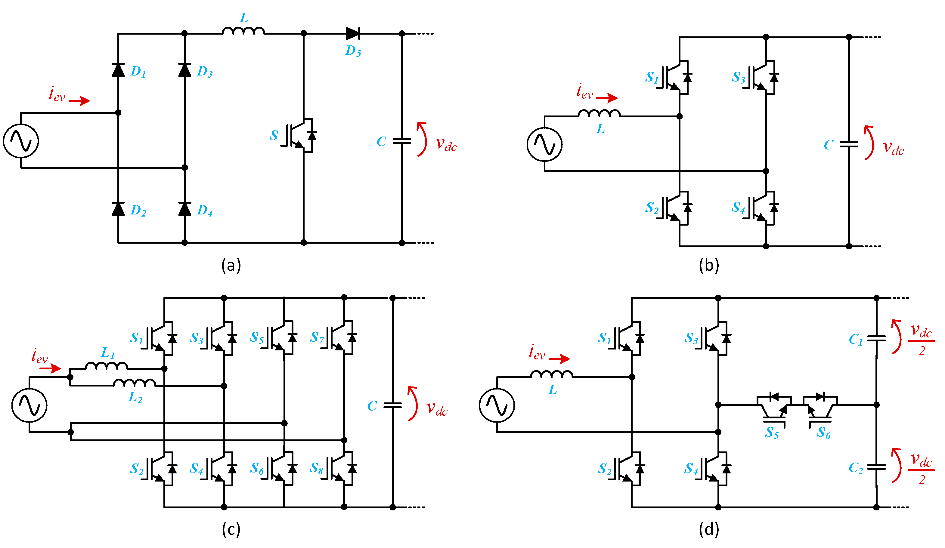
Regarding on-board EVBCs, more specifically, for power electronics converters for the front-end stage, when focusing on unidirectional converters, the main topology is based on the diode ac-dc converter followed by the boost-type dc–dc converter (i.e., the unidirectional power factor correction). This topology has the main advantage of using only one switching device, still guaranteeing the operation with sinusoidal current and unitary power factor. This topology is shown in Figure 3a. On the other hand, in a future perspective of electric mobility as a support for the smart grid, a bidirectional operation is essential, in which the four-quadrant ac-dc converter is used as the main topology (i.e., a bidirectional full-bridge). This converter, shown in Figure 3b, allows bidirectional operation (G2V and V2G modes) without neglecting the sinusoidal current and the unitary power factor. These two topologies are more commonly used. However, when the main objective is to reduce the need for passive filters coupled to the power grid and the maximum current in each semiconductor, to maintain the characteristic of bidirectional operation, the main choice lies in interleaved type topologies. Figure 3c shows the most common bidirectional interleaved full-bridge ac-dc topology, consisting of two four-quadrant ac-dc converters (i.e., dual-phase interleaved topology). When the main objective is to reduce the maximum voltage applied to each semiconductor, as well as to reduce the requirements of passive filters coupled to the power grid, the main choice lies in multilevel topologies. Figure 3d shows one of the most common multilevel bidirectional ac-dc topology (i.e., a topology of five voltage levels).
When focusing on unidirectional converters for the back-end stage, the main topology is based on the buck-type dc–dc converter. This converter, shown in Figure 4a, is easily controllable, as it only has one switching device, and allows the fundamental requirements of battery charging to be met, i.e., charging with constant current (CC) and constant voltage (CV) stages. Additionally, when the objective is to guarantee operation in bidirectional power mode, the main topology that can be used is the half-bridge dc–dc converter. This converter is shown in Figure 4b. This topology operates in buck mode when it is necessary to charge the batteries (i.e., G2V mode), and operates in boost mode when it is necessary to discharge the batteries (i.e., V2G mode). This topology has as an added value the possibility of guaranteeing the battery charging in CC-CV mode, as well as controlling the battery discharge, which can use CC control algorithms or constant power discharge algorithms. As is easy to observe, only one switching device is controlled in each operating mode (i.e., one in buck mode and another in boost mode), providing added value for the optimization of the converter efficiency. However, this converter is non-isolated. Focusing on this last point, when it is necessary to guarantee galvanic isolation, the main topology that can be used is shown in Figure 4c. This topology is simple to control, but only allows unidirectional operation. With this topology, it is possible to control the battery charging process, mainly ensuring controllability in CV mode. On the other hand, when it is pertinent to guarantee the operation in bidirectional mode, the logical option is to use the topology presented in Figure 4d, which is similar to that of Figure 4c, but in which the converters are fully controlled on both dc sides, being called a dual active bridge. With this last topology, it is possible to either charge (i.e., G2V mode) or discharge (i.e., V2G mode) the battery in a similar way to the topology shown in Figure 4b.
Figure 5a presents an example of a developed on-board EVBC. In this system, the topology shown in Figure 3d was used as the front-end converter and the topology shown in Figure 4b was used as the back-end converter. This figure also shows some results obtained during the experimental validation of this on-board EVBC [37]. These results are merely illustrative of the operation principle, having been obtained for the front-end converter. The result of Figure 5b shows the current on the power grid side, allowing to verify that it has a sinusoidal waveform and it is in phase with the power grid voltage. This result is related to the G2V operation mode. The result in Figure 5c also shows the current and the voltage on the power grid side, but, in this case, during the V2G operation mode (i.e., the current and the voltage are in phase opposition).

2.1.2. Off-Board Battery Charging Systems

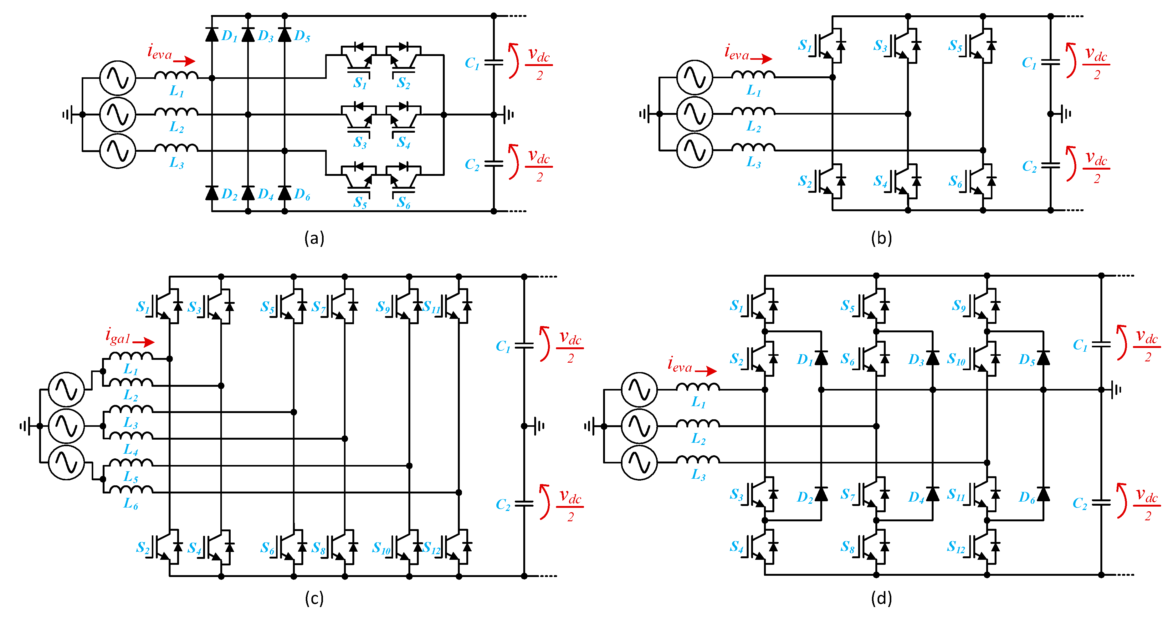
Regarding off-board EVBC, as for the on-board counterpart, there are several options, where the most common are based on a double-stage structure. For the front-end, as these are fast EVBC, the topologies that interface with the power grid are of the three-phase type. Common unidirectional topologies are based on VIENNA-type structures, as the example shown in Figure 6a. This topology consists of a three-phase diode ac-dc converter and an arrangement of switching devices (bidirectional and bipolar cell) connected between each phase of the power grid and the common point at the midpoint of the dc link. This topology only allows unidirectional operation, which may be a disadvantage for off-board charging systems in the future. On the other hand, the three-phase topology that guarantees bidirectional operation and sinusoidal currents on the power grid side, in both G2V and V2G modes, is the full-bridge topology, as shown in Figure 6b. This topology is composed of three legs. The dc link is divided, where the midpoint is connected to the power grid neutral. The maximum voltage applied to each semiconductor is half the voltage of the dc link and the maximum current in each semiconductor corresponds to the maximum current in each phase of the power grid. In this context, when it is desired to minimize the maximum current to which each semiconductor is subjected, one possible solution is to use interleaved topologies. Figure 6c presents a three-phase topology of the interleaved type (double-phase). This topology consists of using, in parallel, two topologies equal to that shown in Figure 6b. Thus, the current of each phase of the power grid is divided by the two legs of each phase, allowing, at the expense of more hardware, the maximum current to be decreased in each switching device. In addition, by applying an adequate modulation strategy (with two carriers with a phase-shift of 180°), it is possible to significantly reduce the ripple of the resulting current in each phase of the power grid. This characteristic is very important, since it can also be useful to reduce the need for passive filters in the coupling to the power grid. As mentioned, with the interleaved topology, the maximum current applied to each semiconductor is reduced, however, the maximum voltage applied to each semiconductor remains half the voltage of the dc link. In this sense, when the objective is to decrease the maximum voltage applied to each switching device, the logical solution consists of using multilevel topologies. Figure 6d shows the most frequently used multilevel three-phase topology. As with the three-phase topologies previously presented, this one also has a split dc link. This topology allows the generation of more voltage levels, and so it is possible to reduce the requirements of the passive filters coupled with the power grid.
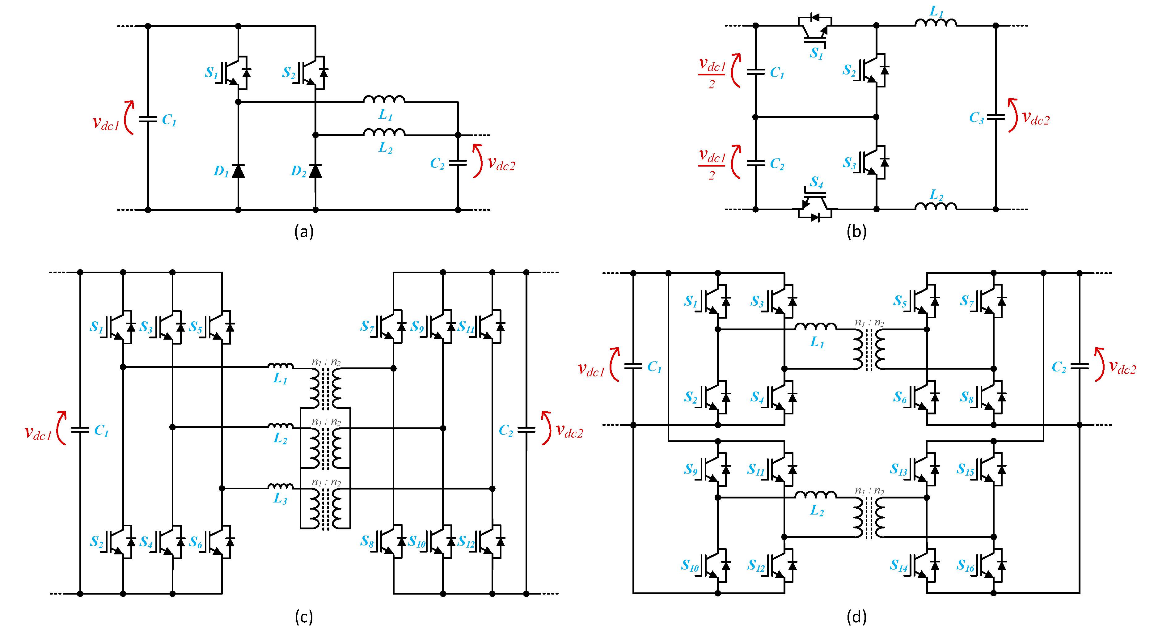
On the other hand, in relation to power electronics converters for the back-end stage of off-board EVBC, the unidirectional topology based on an interleaved structure is the one that allows the performance of the off-board EVBC to be optimized, because the currents are high. Multi-phase interleaved topologies can be employed, however, the simplest is the double-phase, as shown in Figure 7a. As mentioned, this topology allows the operation in interleaved mode, which is a very important feature. In addition to this topology, Figure 7b shows a multilevel topology that also allows the operation in a very similar way to a double-phase interleaved converter. This converter has as its main differentiating factor the possibility of operation with different voltage levels, i.e., the voltage produced by the converter is dependent on the voltage at each dc interface. This converter allows operation in bidirectional mode and, as shown, it consists of four semiconductors, with only two semiconductors being used in each operation mode (i.e., two in buck mode for G2V and two in boost mode for V2G). When galvanic isolation is required, the most common base topologies used are those shown in Figure 4c,d. The latter, however, is designed for higher-order powers. In addition to these possibilities, it is also possible to use three-phase topologies, as shown in Figure 7c. The principle of operation of this topology is very similar to the isolated topologies previously presented, but as an added value, the operating current is divided by the three-phases, each of them feeding a separated isolation transformer, that handles one third of the total operating power. Another possibility of isolated topology that also allows dividing the operating power is shown in Figure 7d. This topology is constituted by the parallel association of several topologies. In addition to allowing to divide the operating power, this topology can also be readjusted for other configurations, e.g., keeping one of the dc interfaces common to all converters (i.e., with a parallel arrangement) and the other dc interface with a serial arrangement of all converters.
Figure 8a presents an illustrative example of a developed off-board EVBC and Figure 8b shows a detail of the power electronics converter. In this system, the topology shown in Figure 6c was used as the front-end converter and the topology shown in Figure 7b was used as the back-end converter. Figure 8b presents some results obtained during the experimental validation of this off-board EVBC [52]. As for the on-board EVBC, these results are also merely illustrative of the operation principle, having been obtained for the front-end converter. The result of Figure 8c shows the three currents on the power grid side, allowing to verify that they have a sinusoidal waveform and that they are in phase with the voltages.

2.1.3. Auxiliary Battery Charging Systems

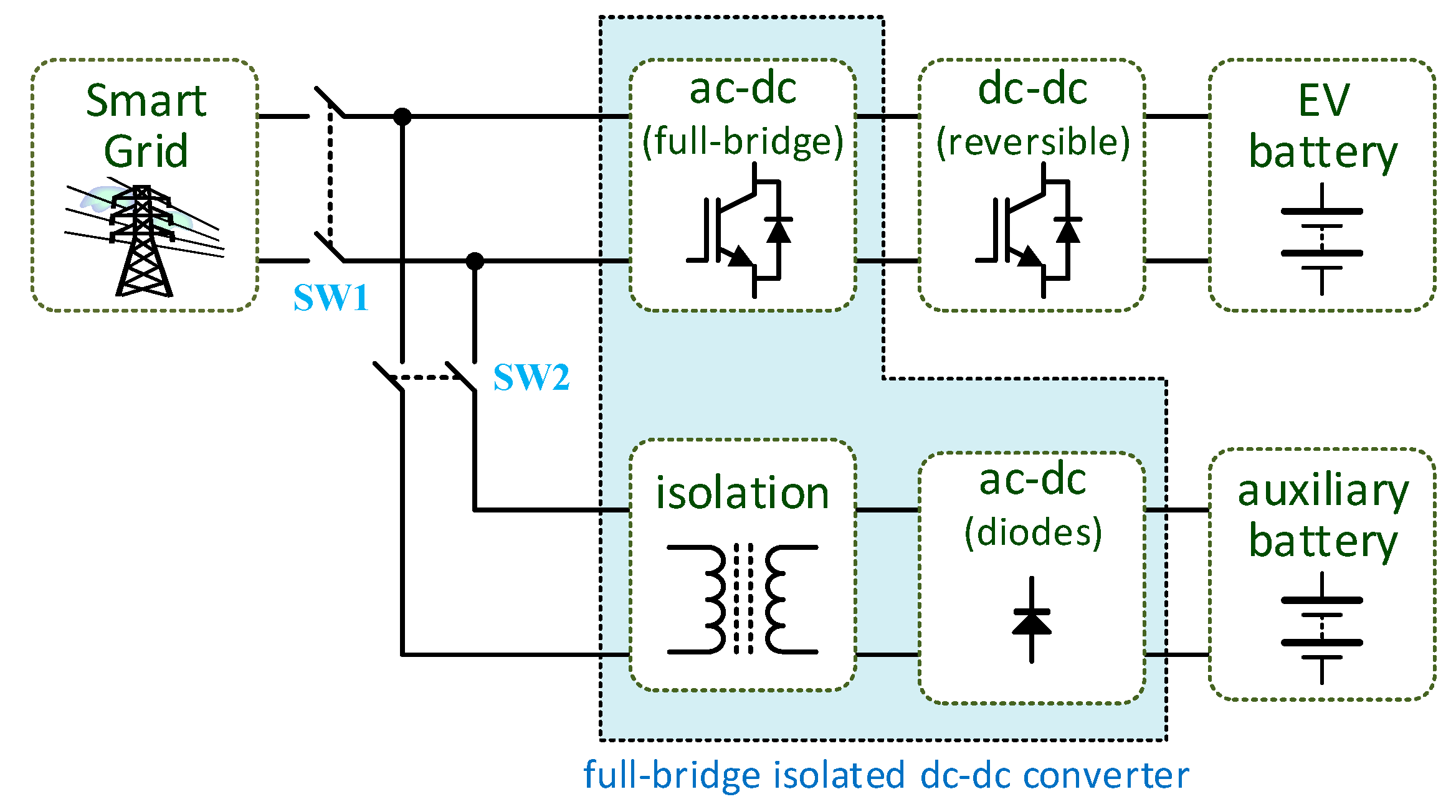
Besides the aforementioned EVBC, the EV must also be equipped with a charging system for the auxiliary battery. In the same way as a conventional vehicle, the internal electronic loads of an EV must be powered by an auxiliary battery (i.e., a low power battery). In such electronic loads are included systems that guarantee driving safety (e.g., lights, windshield wipers, and horn), comfort (e.g., air conditioning and media systems), and driving support (e.g., sensors and global positioning system) [71]. Conventionally, in an internal combustion engine (ICE) vehicle, the auxiliary battery is charged via an electric generator, named as alternator, which is coupled to the ICE. In contrast, in electric and hybrid vehicles, this charging operation takes place through a dc–dc converter which is connected, on the higher voltage side, to the traction battery. For this task, isolated dc–dc converters must be used because, according to the IEC 61851-1 standard, it is mandatory that the traction batteries are isolated from the vehicle chassis. In [72] is presented a power electronics solution based on an integrated converter to enable the energy exchange between two batteries with different voltage levels. A three-port converter topology based on the triple active bridge converter is addressed in [73], a system that allows auxiliary battery charging from the traction battery with galvanic isolation ensured by a three winding high-frequency transformer. In [74], a method for controlling the auxiliary battery charging via the traction battery is patented, where the auxiliary battery charging is carried out, whenever possible, during the standby of the EV, and according to the state of charge of both auxiliary and traction batteries. In [75], an integrated solution based on power electronics is presented for charging the auxiliary battery from the traction battery, identified as traction-to-auxiliary mode. In the presented on-board solution, shown in Figure 9, a unified converter topology, the EVBC can be configured in an isolated full-bridge dc–dc converter the auxiliary battery charging, thus making the traction-to-auxiliary mode possible. In [76], a topology based on the combination of a boost-type dc–dc converter and a flyback converter is presented for auxiliary battery charging, where the primary side of the transformer of the flyback converter is used as the input inductor of a boost-type dc–dc converter where the EV battery is connected to. In [77], it is presented a strategy without auxiliary battery, where the loads are supplied by the EV battery. An intermediate 48 V dc link was considered and implemented by means of a buck-type dc–dc converter, to which the EV battery is connected on the higher voltage side. In this situation, a transformer is used to ensure galvanic isolation. In the created 48 V dc link, several dc–dc converters are placed, also based on the buck-type dc–dc converter, which result in voltages of 12 V to supply the various auxiliary loads. The availability of a 48 V dc link is considered to be more efficient when compared to the traditional 12 V dc link, since, for the same power, a higher voltage allows the use of electrical cables of smaller section that are, consequently, lighter [76].

2.2. Inductive Wireless Battery Charging

Cored inductive power transfer is a popular technology that has been extensively used since the electric transformers have been invented [78], and it is based on the magnetic induction effect observed and explored by Michael Faraday in 1831 [79,80]. When two coils are wound around a body of magnetic material (the “core”), their electrical behaviors are mutually interdependent. This happens in such a way that energy can be exchanged between the coils and, ultimately, between the circuits they are connected to, by means of a commonly shared magnetic field. This is not itself an invention, but rather, a natural phenomenon that is easier to observe when the core material has a high magnetic permeability, but that also occurs even if the core is constituted by air or, simply, by vacuum. In these latter cases, where there is no solid material to serve as a path for the magnetic field all the way between the two coils, the pair of coils form an “air-gapped” magnetic coupling, and the phenomenon is often referred to as “wireless” power transfer (WPT) or, more precisely, inductive wireless power transfer (IWPT).
Soon it was realized that, in IWPT, the transmission of energy was not efficient to 100%. The energy losses were later explained by: (i) the energy dissipated in the electrical resistance of the conductors of both coils; (ii) the energy dissipated in the core material (if not air-gapped), that can be due to either induced parasitic (eddy) currents or magnetic reluctance; (iii) the energy that is irradiated to free-space by the coils. All these losses vary with the working frequency. Noticeably, the frequency dependency of conductive losses in (i) is due to skin and proximity effects [81], which results from the interaction of the conductor with the magnetic fields respectively generated by the current passing on that same conductor and other nearby conductors, making the current distribution uneven along the conduct cross-sections, and thus, increasing the apparent resistance of the coil windings.

2.2.1. Principles of Inductive Wireless Power Transfer

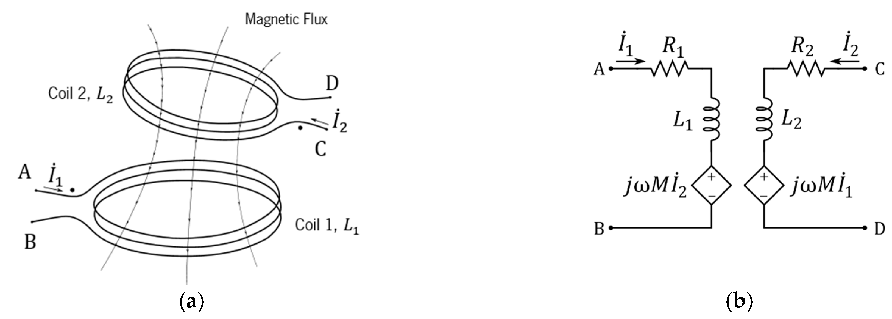
In both “cored” or “wireless” versions, when submitted to sinusoidal oscillations of sufficiently low frequencies (negligible irradiated power), the magnetic coupling voltages and currents can be modeled in terms of phasors by ideal linear circuit components, as shown in Figure 10.
In this model, ω   =   2 π f 0 , and M is the mutual inductance between the coils. R 1 and R 2 depend on both skin and proximity effects. For any fixed frequency operation f 0 , the skin losses can be taken into account by recalculating these R i for that frequency, and the model will still conserve its linearity. In this manner, with no irradiation assumed for the magnetic coupling, the power transferred from Coil 1 to Coil 2 is given by the phasor S ˙ 1 , 2 (1):
S ˙ 1 , 2   =   V ˙ M 1 I ˙ 1 *   =   V ˙ M 2 ( I ˙ 2 * )   =   j   ω   M   I ˙ 1 *   I ˙ 2   =   j   ω   M   I ˙ 1   I ˙ 2 *   ,
and the average real power P 1 , 2 transferred is then given by:
P 1 , 2   =   ω   M   I r m s 1 I r m s 2 sin ( φ 1 φ 2 ) ,
where φ 1 φ 2 is the phase angle between the current in Coil 1 (primary coil) to Coil 2 (secondary coil). If P 1 ,   2 < 0 , the power is actually transferred backwards, that is, from Coil 2 to Coil 1.
In order to increase P 1 ,   2 , I r m s 1 and I r m s 2 have to be increased while keeping the phase delay of I ˙ 2 with respect to   I ˙ 1 as close as possible to π / 2 . This is achieved by introducing compensation networks in primary and secondary circuits. The simplest and first engineered compensation network is constituted by a single capacitor in series with the load, as shown in Figure 11b, a configuration already used by Nikola Tesla in the late 19th century [82], which is called “series compensation”. In this configuration, the reactive component of the equivalent impedance Z ˜ 2 , as seen by E 2 , is canceled at ω = 2 π f 0 when L 2 C 2 = 1 / ( 2 π f o ) 2 .
Conditioned to the choice of the phase difference φ 1 φ 2 =   π / 2 , the use of a similar serial compensation network in the primary side, as shown in Figure 11, can on the other hand maximize the current I r m s 1 and, consequently, maximize the power dissipated on E 1 , which is in fact transferred to the secondary and delivered to the load via R 2 by E 2 . Having the capacitor C 1 as the free variable, | Z ˜ 1 | is minimized, and I r m s 1 is maximized (resonant condition on the primary circuit), when L 1 C 1 =   1 / ( 2 π f o ) 2 .
The serial compensation, when used in both the primary and secondary circuits, originates what is called the serial-serial (SS) compensation topology, one the most widely used configurations for IWPT. It has been shown [83,84], that in a passive two-port network, such as an SS-compensated magnetic coupling, when both primary and secondary circuits “tuned” to f o , the maximum achievable electrical efficiency η m a x   in the power transference from Coil 1 to Coil 2 at f o can be calculated as:
η m a x   =   k 2 Q 1 Q 2   ( 1 + 1 + k 2 Q 1 Q 2 ) 2   ,  
where the Q i are the quality factors (or “Q-factors”) of the coils L i , defined by:
Q i   =     ω 0   L i   R i ,         i { 1 ,   2 }
and this happens when the load resistor R L assumes the value:
R η m a x   =   R 2   1 + k 2 Q 1 Q 2  
For values of Q F = k   Q 1   Q 2   much greater than 1, η m a x can be approximated by:
η m a x   η ˜ m a x   =   1   2   k Q 1 Q 2     =   1   2   Q F
The behavior of η m a x as function of the magnetic coupling quality factor, Q F = k   Q 1 Q 2 , is shown in Figure 12a, revealing for instance that in order for a magnetic coupling to allow electric efficiencies over 85% it necessary that Q F > 12.3 .
Typical behavior patterns of the efficiency as a function of the normalized   R L to   R 2 ratio are shown in Figure 12b, where the color of the plotted curves, ranging from red (lower curve) to blue, correspond respectively to Q F values ranging from 1 to 100 in the set { 1 ,   2 ,   5 ,   10 ,   20 ,   50 ,   100 } . Noticeably, the maximum efficiency for each curve in Figure 12b is always achieved when condition (5) is met, that is, when R L / R 2 k   Q 1 Q 2 .
Once established, the IWPT overall efficiency and the required efficiency for the magnetic coupling, the desired power level can set by adjusting the voltage source V 0 . If this cannot be directly accomplished because the power source is fixed, a voltage transformation should be used in either the primary or secondary circuit. If the load R L requires dc current instead, it will be usually connected to the secondary circuit through a rectifier and a dc filter. In this case, a dc–dc converter can be used to match the load for optimal efficiency. However, as a rectifier is a non-linear element, the characteristic output response curve will be not linear as well, and a new optimum R L , R η m a x D C , will arise, which is potentially different from R η m a x (5), as observed in [85].
The task of building a magnetic coupling with a reasonably high efficiency translates into the problem of building resonant coil-capacitor pairs with high-quality factors Q i , as high as necessary to compensate for the low magnetic coupling coefficient k between these coils.

2.2.2. Frequency Splitting in Serial-Serial (SS)-Compensation Topology

It is long known that, in a double-tuned coupled circuit, when the mutual inductive coupling coefficient is increased above a critical value, two resonance peaks in frequency may appear instead of one, when R L is lowered (highly loaded secondary). This phenomenon, early observed and used in the design of communication circuits, was called frequency splitting [86].
These frequencies are often referred to in the literature as   f o d d , which is lower than the resonance frequency   f 0 , and   f e v e n , which is higher, and can be approximated by:
f e v e n 1 1 k f o   ,
f o d d 1 1 + k f o   ,
as long as k   >   k s , where k s is a critical value that is a function of the loaded quality factor of the secondary of the magnetic coupling [87].
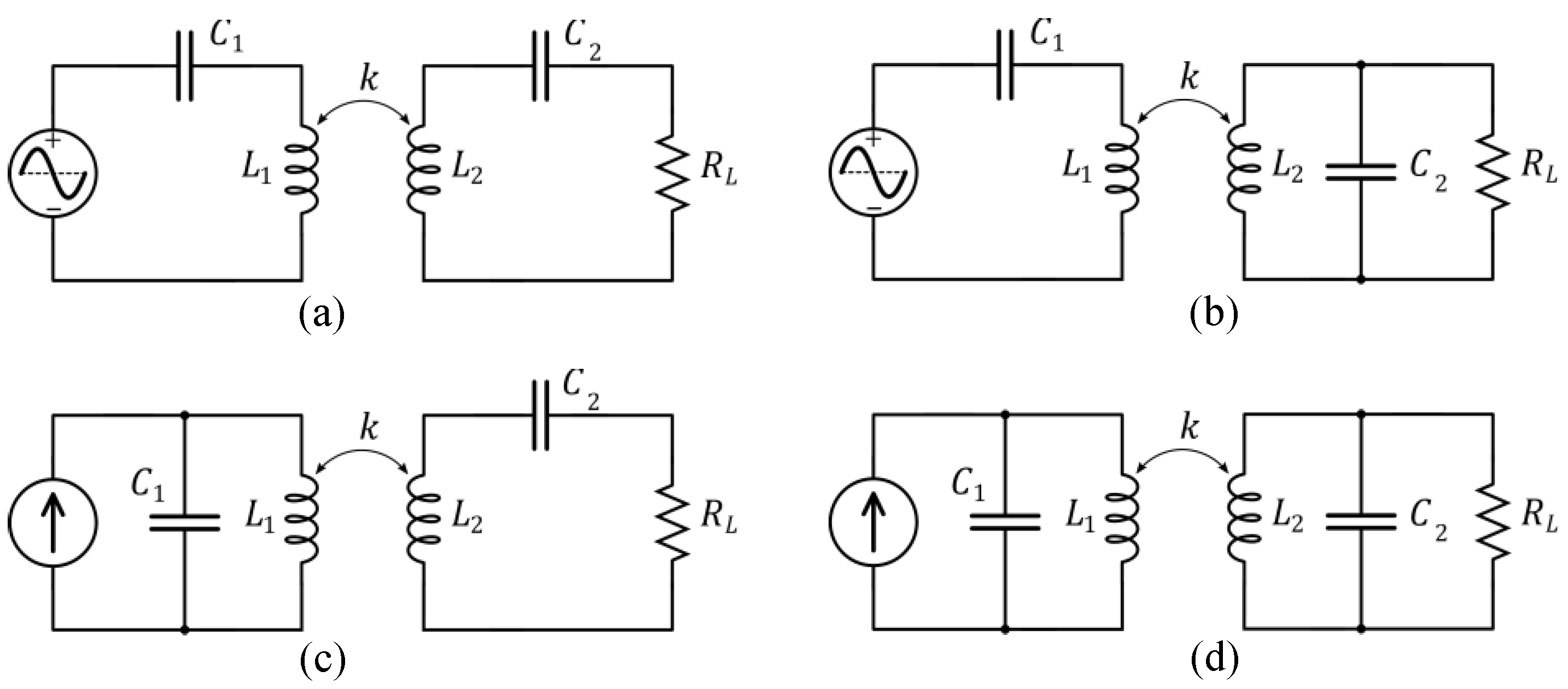
This behavior and its simplified formulation, as given by (7) and (8), have been characterized by many other authors since Terman [81], and also need to be considered in IWPT design, either to avoid the frequency splitting operation [88,89] or to exploit it, and tune circuits to the most adequate operating frequency [90]. Frequency splitting, however, is not unique to SS-compensated circuits. This phenomenon can occur, and be exploited, in other circuit topologies, due to the presence of multiple poles in the circuit transfer function and the joint dependence of their location on the coupling coefficient and the load. For all basic IWPT configurations, as displayed in Figure 13, it has been shown that frequency splitting is prone to be observed whenever the loaded quality factor of the primary is lower than the loaded quality factor of the secondary [91].

2.2.3. Other Circuit Compensation Topologies

Another similar compensation topology, which is also of simple construct and often used in IWPT applications, is the serial-parallel (SP) compensation [92], where on the secondary side there is a capacitor in parallel with the load. Different compensation topologies yield different characteristics that will influence the choice of the compensation type to use in a design. Formulations found in the literature can help the design in the simpler cases [93], as exemplified in this work for the SS-compensation circuit, with coils of high-quality factors that are not heavily loaded. However, in general, exact algebraic analysis is impractical, and numerical simulation is the prevalent tool for both IWPT evaluation and design.
The SS- and SP-compensated topologies are possibly the most popular so far observed in academic studies and most real-world implementations. Excited by an ac voltage source in the primary side, they are simpler to implement, easier to analyze than the more complex topologies, and still can successfully handle a large number of applications. For wireless vehicular battery charging, with power ranging from a few kilowatts to a few tens of kilowatts, a number of laboratory implementations report the use the SS- and SP-compensation schemata, such as [94], with some authors having identified efficiency advantages of the SS over the SP-compensated circuits for this type of application [95]. This advantage can be relativized by the fact that the parallel compensation may be the preferable topology to be used if high currents and power levels are to be achieved, and either the input or output voltage is restricted not to be very high. This will often be the case in circumstances where the mutual inductance between the coils is low. Concerning efficiency, it will improve if the passive components of the compensation circuits and the magnetic coupling exhibit losses altogether, for the same output power handled. This is more related to the quality factor of the components themselves and the choice of the more favorable operation point, which may be different for each topology, similarly to what happens with the output power itself. This is exemplified by a case study [96] where the SP efficiency is reported to be better than that of the SS-compensation when lower magnetic coupling coefficients, resulting from asymmetry in the coils, are observed, but worse otherwise.
Similar to the SS- and SP-compensated circuits, parallel-parallel (PP) and parallel-series (PS) compensation circuits are defined, by alternatively using a capacitor in parallel in the primary as a compensation device, a configuration that requires, instead, excitation from an ac current source. The SS, SP, PP and PS topologies are summarized in Figure 13, where, for simplicity, the resistors corresponding to the losses in the coil windings have been omitted from the models.
Other topologies using arbitrarily more complex passive circuits can also be used to match the load to the power source through a magnetic coupling. There have been many authors investigating this topic and extensive reviews on compensation topologies and their main properties can be found for instance in [97,98] for a general design orientation.

2.2.4. Power Electronics Topologies for Inductive Wireless Power Transfer (IWPT)

IWPT operation can be either unidirectional or bidirectional. In unidirectional operation mode, an active power electronics topology should be used in the primary-side and a passive power electronics topology could be used in the secondary-side, while in bidirectional operation mode, it is indispensable to consider active power electronics topologies in both the primary side and secondary sides. Another important specification is related to the interface with the power grid, since both single-phase and three-phase interfaces are valid. The same power electronics converter topology can be used in both the primary side or secondary side, or a mixture of circuit topologies can be used for the same IWPT application (i.e., distinct topologies on both sides).
A comprehensive and broad review of ac-dc power electronics converters, both unidirectional and bidirectional topologies, as well as power control theories, is presented in [99], showing good candidates for IWPT applications. Specific reviews of ac-dc power electronics converters with galvanic isolation are presented in [100,101]. The covered topologies are relevant to prevent power quality issues on the power grid side and due to the galvanic isolation, however, the complexity is a discouraging factor for IWPT applications. Analyzing in more detail the most convenient power electronics topologies, the main option is the full-bridge, shown in Figure 14a. This topology is constituted by two legs, where each one is constituted by two power devices. This topology is very relevant since it can operate in four-quadrants and with three voltage levels, depending on the control strategy, which is an important characteristic when it is necessary to diminish the necessities of the coupling passive filters. Aligned with the full-bridge power electronics topology, the half-bridge, shown in Figure 14b, is also pertinent for IWPT applications. As is possible to verify, it is constituted by a single leg (i.e., half of the power devices and half of the associated hardware), but it requires a split dc link. Due to this fact, the maximum voltage of the dc link is double when compared with the full-bridge, as well as the voltage applied to the power devices. Moreover, this topology only operates with two voltage levels, demanding more in terms of coupling passive filters.
Besides the aforementioned power electronics topologies, multilevel converters (i.e., more than the three of the full-bridge) are also relevant for IWPT applications, since it is conceivable to obtain a voltage waveform with improved quality, allowing the requirements of the coupling passive filters to be reduced. However, the hardware and software necessities are more relevant (e.g., more power switching devices, drivers, and more sensors). In counterpart, the maximum voltage applied to each power device is reduced in proportion to the voltage levels obtained with the multilevel topology. Moreover, besides reducing the necessities of the coupling passive filters, this is also important to improve the efficiency. Specifically, in [102,103] are presented extensive reviews regarding power electronics topologies with multilevel characteristics. In this context, Figure 14c presents a multilevel topology capable of producing five voltage levels [104], and suitable for IWPT applications. As shown, this topology is composed of a traditional full-bridge converter and by a specific bidirectional and bipolar structure between the neutral wire and the middle point of the split dc link. This converter also allows four-quadrant operation. The cascade h-bridge [105] is also an interesting power electronics topology to guarantee a multilevel characteristic, however, it can be applied only for specific IWPT applications, since it requires independent dc links. Depending on the voltage of the dc links, two distinct structures of the cascade h-bridge can be used: symmetric and asymmetric [106]. It is important to note that by using an asymmetric structure, it is possible to obtain more voltage levels without changing the hardware. Also within multilevel structures, the neutral point clamped and the flying capacitor are traditional solutions [107,108] both with potential for IWPT applications.
Additional to the aforementioned topologies, other specific topologies can be considered for IWPT. For instance, a cascaded dc–dc converter based on a boost-buck structure is proposed in [109] for the dc-side of a unidirectional IWPT, allowing to control both the input as well as the output current. A new pulse-density modulated for the full-bridge converter operation with zero-voltage switching is presented in [110] for IWPT, which is proposed as an advanced technique for improving the efficiency. An ac-dc converter based on a single-stage three-level structure is proposed in [110] for unidirectional IWPT, operating with fixed switching frequency and incorporating, as an innovative feature, power-factor-correction features for the power grid side. A single-phase ac-dc converter based on a matrix structure is proposed in [111] for the primary-side of a bidirectional IWPT, operating as a single power stage and designed for electric mobility applications. A single-stage resonant converter based on a bridgeless boost-type structure is proposed in [112] for unidirectional IWPT, allowing combining in a single equipment the necessary functionalities for the power transfer, as well as for the power grid side with a sinusoidal current and unitary power factor. A novel control strategy for bidirectional IWPT in proposed in [113], which is specially dedicated to controlling structures based on the full-bridge dc–ac and ac-dc converters. A bidirectional IWPT using self-resonant PWM for applications in electric mobility is proposed in [114], permitting to obtain constant frequency accomplished with a big air-gap and without the required supplementary circuit. A three-phase single-stage ac-dc converter for unidirectional IWPT is proposed in [115], allowing it to operate as a power factor correction topology for the power grid interface. A direct ac–ac converter for unidirectional IWPT is proposed in [116], permitting to obtain a single-stage structure with an active source current control. A Z-source resonant converter is proposed in [117] for unidirectional IWPT, guaranteeing both the functionalities of power transfer and power quality on the power grid side.

2.2.5. Stationary Battery Charging of Electric Vehicles with IWPT

Because of the large number of possible design solutions involving coil geometry and circuit implementations, and in pursuit of interoperability, SAE International (previously known as the Society of Automotive Engineers) sponsored a workgroup that produced a report establishing some common guidelines for IWPT design of vehicular wireless battery charging systems, the SAE Recommended Practice J2954 [118]. The SAE solution is basically an under-the-vehicle installation, as shown in Figure 15.
As defined in SAE J2954, the secondary coil is included in a structure denominated “Vehicle Assembly” (VA), and the primary coil in the “Ground Assembly” (GA), as marked in Figure 15. Without determining specific electronic implementation, the SAE J2954 establishes power transfer classes, and fixes minimum performance parameters regarding the geometry and alignment tolerances between primary and secondary coils. It also provides examples of viable circuit implementations. Table 1 and Table 2 provide a summary of SAE proposed classes of IWPT power and clearance distances from VA to ground.
In SAE J2954, the efficiency is required to be greater than 85 % in the best possible alignment condition (“full alignment”). The base IWPT frequency can be adjusted within the established band from 81.38 kHz to 90 kHz. The feedback for this adjustment can come from several different sources, from direct impedance and power signal measurements, at the primary side, to explicit message passing through a wireless communication link established in between the primary and secondary control circuits, as proposed in SAE Recommended Practice, SAE J2847-6 [119], that establishes requirements and specifications for communication messages between wirelessly charged EVs and the wireless battery charger. This is a complex and relatively new technology that has been recently proposed, but implementations using it are already reported [120].
Although not enforcing any particular circuit implementation, SAE 2954J suggests some viable circuit topologies. In particular, it exemplifies and provides actual circuit parameters for PP-compensation and for the so-called LCC-compensation [121], that can be used either on primary or secondary sides, or on both [122], as shown in Figure 16. The LCC term comes from “inductor-capacitor-capacitor”, which is exactly the sequential order of the passive components that are introduced in between the power source (or the load) and the magnetic coupling. LCC exemplary circuits are provided in SAE 2954J with specific component values assigned, to facilitate an implementation where the required performance levels are assured to be met.
The circuit used to implement the rectifier can be made, by design, the same as that used in the inverter, such as the full-bridge converter/rectifier, case when only the control of the gates of the converters will differ, from primary to secondary. This facilitates the implementation of bidirectional IWPT [123,124,125] which may be very useful in V2G or vehicle-to-home (V2H) applications [126,127]. As vehicular bidirectional battery charging itself generates more possibilities for applications, even in conductive charging, it can be expected that bidirectional IWPT also becomes popular. Honda and WiTricity particularly have already demonstrated the feasibility of a SAE J2954-compatible wireless bidirectional battery charger [128].

2.2.6. Limiting Human Exposure to Electromagnetic Fields (EMF) in IWPT Systems

The concern about human health in the design of electric apparatuses is not unique to IWPT devices. However, due to the very nature of near field energy transmission in IWPT, the frequency and intensity of electromagnetic fields (EMF) in the vicinity of the coils can be very high, above what is currently considered safe for human exposure. The International Commission on Non-Ionizing Radiation Protection (ICNIRP), considering the knowledge available on the subject, periodically reviews and updates some guidelines for limiting exposure to time-varying electric and magnetic fields. In the frequency band recommend by SAE J2954 for wireless charging, the limit rms electric field and magnetic flux density are respectively 83 V/m and 27 µT [129].
SAE J2954 requirements, however, are stricter than the general ICNIRP recommended safety margins: in some positions of the space, inside and around the car, due to the consideration that some humans exposed to the automotive application may have an implanted medical device (IMD), such as cardiac pacemakers, the AAMI/ISO 14117-2012 standard should also be applied. Because of that, inside the cabin, and at any point in space outside the vehicle that is located higher than 70 cm above ground, the required maximum rms values of the magnetic field strength is further limited to 15 μT, with the peak magnetic field limited to 21.2 μT. SAE J2954 admits that conformity may still be observed if this additional requirement is not met in these critical spaces, but in this case, steps should be taken to warn pacemaker wearers to avoid this region, that is, to stay away from the car. In practice, in order not to restrict in any manner the use of cars by passengers with IMD, this additional requirement has to be observed [127].

2.2.7. Dynamic Inductive Wireless Power Transfer

In addition to wirelessly charging the batteries of vehicles that are stationary over a charging pod by means of IWPT, there is an increasingly active research line worldwide to implement dynamic inductive wireless power transfer (DIWPT) [130], that is, to transfer power to the vehicles while they are moving along the road. This allows the battery size capacity and cost to be reduced, or even the battery suppression in some specific applications. This idea was described in a 1891 patent from Maurice Hutin and Maurice Leblanc [131], only about 10 years after the introduction of the first electric cars running on tracks, in 1881 [132,133] although it is not known to have been actually implemented at that time. Pursuing the same ideals of Hutin and Leblanc, George Ilyich Babat designed, prototyped and, in June of 1943, successfully demonstrated what he called the “High-frequency Transport” [134,135] which was the first DIWPT system currently reported to have been publicly demonstrated. It included all the electronics for powering modular inductive lanes, as well as harvesting and rectifying the electric current on board of a vehicle. However, Babat’s prototype operated at very low efficiency levels, due to technological limitations of that time. Possibly because of this, the DIWPT applications remained forgotten for decades. In 1974, the idea was rediscovered and a system was proposed by John Bolger [136,137]. Following Bolger’s work, several other pioneering designs and projects with the same goal were established: the roadway powered electric vehicle (RPEV) [138,139] from 1979 to 1986; the developments at the University of Auckland [140,141] in the 1990s, the on-line electric vehicle (OLEV) at the Korea Advanced Institute of Science and Technology (KAIST), since 2009 [142,143,144,145].
In the OLEV, for instance, the system architecture was developed in sequential generations, the first in 2009. The system uses ferrite-cored oblong primary coils buried beneath ground level. These coils are energized with ac currents of about 200 A at 20 kHz, in the first development phases, then 60 kHz was used. The SS-compensation topology was adopted [146], in the same manner as it would be in a standard stationary IWPT. The long primary coils create a planar symmetry that keeps the coupling characteristics independent of the particular position of the vehicle along these coils, except if the vehicle is very close to the coil extremities. The coupling coefficient may vary as the vehicle drifts transversally to the lane, but since the magnetic coupling is not high, the resonance frequency is kept approximately constant, thus facilitating the IWPT implementation [147]. Common to all other DIWPT designs where the vehicle can freely move on the plane of displacement, the lateral misalignment is one of the most critical parameters to be controlled. If it is too large, an excessive reduction of the magnetic coupling coefficient occurs, causing the efficiency to drop and, ultimately, the transmitter power as well.
Despite all these technical difficulties, DIWPT was soon recognized as a promising research effort, attracting the contribution of many groups around the world, among them [148,149,150,151,152]. More recent projects, involving both scientific and industrial partners, such as the FABRIC European project [153,154,155,156] have further advanced the technology. However, the proposed solutions are complex, and so are their cost, which is still being fully assessed, and represents a major challenge for the widespread adoption of the technology.
Because of that, new enterprises are trying to develop DIWPT systems that are more accessible, but at the same time, up-scalable. One of them, Electreon Wireless, from Israel, is deploying and evaluating, along 2020, the first DIWPT pilot project over one kilometer, in the Isle of Gotland, Sweden [157]. The system is built around a 20 kW IWPT module that is reported to achieve 88% to 90% efficiency and works with a large air-gap, of about 24 cm to 27 cm, allowing the primary coils to rest 8 cm beneath the ground surface, a characteristic that shall increase safety and durability [130].
Most of the research and development efforts in DIWPT are directed to standard size road vehicles, targeting the electrification of the urban fleet with minimum impact to the composition of the service matrix delivered by the currently in use ICE vehicles. However, the application of DIWPT to soft mobility transportation is also being investigated.
A DIWPT lane module for e-bikes and similar low-cost lightweight EVs, as shown in Figure 17, has been developed using a PS-compensated IWPT architecture. The primary, on the lane side, is driven by a resonant inverter and wirelessly energizes the power train of an electrically assisted bicycle adapted with a pick-up coil around the rear wheel [158]. The activation of the module power is triggered by the detection and positive identification of a radio frequency identification (RFID) tag placed at the pick-up coil [159,160]. The excess energy transferred during the transit over the lane modules is stored on-board, and it is enough to keep the vehicle running on electricity also over the non-electrified inter-module gaps, provided that consecutive modules are not too far apart from each other.
Overall, the DIWPT can be considered a promising technology, still in its early stages, and the identification of all its possible applications to transports is yet to be unveiled. The stationary wireless battery charging with IWPT, on the other hand, was commercially introduced only about three years ago [161], but can already be regarded as a newly consolidated technology, with a growing market, that is predicted to expand at a compound annual growth rate estimated between 36% [162] and 60% [163] during the next years, reaching a total market share on the order of USD 200 million by 2025.

2.3. Power Electronics for Traction Systems

Over the past few years, the technological advances in the field of power electronics have created new opportunities for the use of various types of electric machine for automotive applications, where characteristics such as high starting torque, high power density and high efficiency have always been regarded as fundamental. The dc machine was, at the beginning of the 20th century, the most used electric machine for applications related to traction systems due to its ability to produce high starting torque and ease of speed or torque control [164]. However, the presence of brushes and mechanical commutators requires recurrent maintenance and consequently increases the costs of this solution. As an alternative to these machines, brushless dc (BLDC) machines appeared, which are characterized by their high starting torque, high efficiency and absence of mechanical commutators [165]. In addition to these characteristics, they are especially suitable for applications that require high power density and, therefore, are recommended for electric mobility applications [166,167]. Regarding BLDC machine types, these can be divided into two categories [168,169]: out-runner type electric BLDC machine and in-runner type BLDC machine. An example of an EV that uses a BLDC machine is the Honda-e [170].
Similar to the BLDC machines, permanent magnet synchronous machines (PMSMs) have been around for several decades for numerous applications, as presented in [171,172,173,174,175,176,177,178]. These types of machine, also known in the literature as brushless ac and permanent magnet ac motors, uses permanently magnetized magnets to create the magnetic flux, thus avoiding the need for a dc source, as well as the respective slip rings and brushes. This increases the reliability as well as the power density of the electric machine, making viable its application in EVs [165,179]. Although they have existed for several decades, PMSMs started to gain more popularity during the last decade due to the emergence of new metals used in the manufacture of permanent magnets, as well as due to the innovative construction alternatives for manufacturing this machine as demonstrated in [180,181,182,183,184,185,186,187]. Despite the aforementioned advantages, PMSMs have a high acquisition cost due to the rare metals used in permanent magnets. Many vehicle manufacturers use PMSMs in their EVs, e.g., Toyota Prius, Ford Focus Electric, Nissan Leaf, BMW i3, Chevrolet Bolt EV [164,188,189].
Another type of electric machine that has been gaining popularity in recent years in EV applications is the three-phase induction machine. Compared to the previously presented electric machines, the three-phase induction machine, in particular the induction machine with a squirrel-cage rotor, has the advantage of not having to provide energy for rotating parts. In addition, they do not have permanent magnets such as PMSM and BLDC machines, which means that they are more affordable. However, the implementation of permanent magnets in the induction machine is also possible, as investigated in [190,191,192], to improve some characteristics such as power factor, efficiency and torque. Nevertheless, the induction machine has the disadvantage of not differentiating the magnetization of the winding power supply itself, which, in EV applications, translates into a greater amount of energy required from the batteries [165,179,193]. Despite this disadvantage, its high-performance capability is already proven through some models already available on the market, such as Tesla’s EVs Roadster, Model S and Model X, Mahindra Reva e2o, Honda Fit EV, which use this type of machine for their propulsion [164].
More recently, boosted by the advances in power electronics and digital control systems, reluctance machines have emerged, presenting as main feature a robust and simpler construction, when compared with the electric machines previously discussed [194]. The rotor of these electric machines consists of a piece of rolled steel with no windings or permanent magnets. This characteristic makes it possible to reduce the rotor’s inertia and, consequently, increase its acceleration, contributing to applications where high speeds of rotation are required. In addition, as the heat produced is mainly confined to the stator, it becomes easier to cool this type of electric machine. These machines combine the efficiency of synchronous machines, since they have no slip, with the absence of permanent magnets as seen in induction machines. Regarding reluctance, they can branch out into stepper motors, synchronous reluctance machines and switched reluctance machines [195,196]. There are also hybrid reluctance permanent magnet machines, which combines the performance of PMSM and reluctance machines, allowing an additional degree of freedom for the control [197,198,199,200]. These electric machines are a recent, but promising technology in the field of electric mobility [201,202,203,204,205,206,207,208,209,210].
In [211] an analysis and a comparison among PMSMs, switched reluctance machines, and induction machines are presented, focusing on EV applications, as well as other types of applications, such as aircraft, ships, and trains.
The selection of an electric machine for the traction system of an EV falls not only on the quality/price criterion but also, and increasingly, on an acceptable mechanical and electromagnetic performance [212,213]. Any EV makes use of an electric machine that needs to be controlled according to the driver’s preference. The control of an electric machine can be either applied to the rotational speed or to the torque, in either case with the reference variable being controlled by the driver. The speed control is related to cruise control systems, where the driver defines the reference speed of the EV that will result in a given rotational speed for the electric machine. On the other hand, the torque control consists of the most common approach in vehicles in general, with the accelerator pedal of the vehicle being used to establish a reference torque for the electric machine. Nonetheless, in both cases, the electric machine needs to be controlled, where it is of utmost importance to measure and control the voltage, current, and frequency variables. Therefore, power electronics converters are indispensable for driving the electric machines, since they are able to produce the required voltage, current, and frequency in each instant, guaranteeing the proper operation of the electric machine.
The power electronics converters for EV traction systems, as well as for other applications, can be classified in accordance with the passive elements present in the dc link. These can be classified as voltage source converters, where the energy storage element in the dc link is a capacitor, storing energy in the form of an electric field, or current source inverters, where the energy storage element in the dc link is an inductor, storing energy in the form of a magnetic field. The topologies of power electronics converters are also related to the type of electric machine that needs to be driven (for instance, switched reluctance machines use a different power converter topology than those of PMSMs or induction machines).
The majority of applications in the field of power electronics is supplied with voltage sources. This type of converter is generally more efficient than its current source counterpart. Additionally, it has capacitors in the dc link, which are less bulky and heavy than inductors for similar power levels. The capacitance value of these capacitors must be high enough to smooth the ripple currents generated by the switching of the power semiconductors, and the root mean square (rms) value of the dc link current can vary between 50% and 80% with respect to the electric machine nominal current [212].
In order to drive dc electric machines, generally, it is used the power converter present in Figure 18a. This converter allows the operation of the electric machine in four quadrants, i.e., allowing the rotation of the machine in both directions with the possibility of performing regenerative braking also in both directions. The power converter comprises four fully-controlled power semiconductors and a capacitor bank in the dc link. Besides adjusting the polarity of the voltage, and consequently the direction of the current applied to the electric machine stator winding, this converter also allows the controllability of both variables.
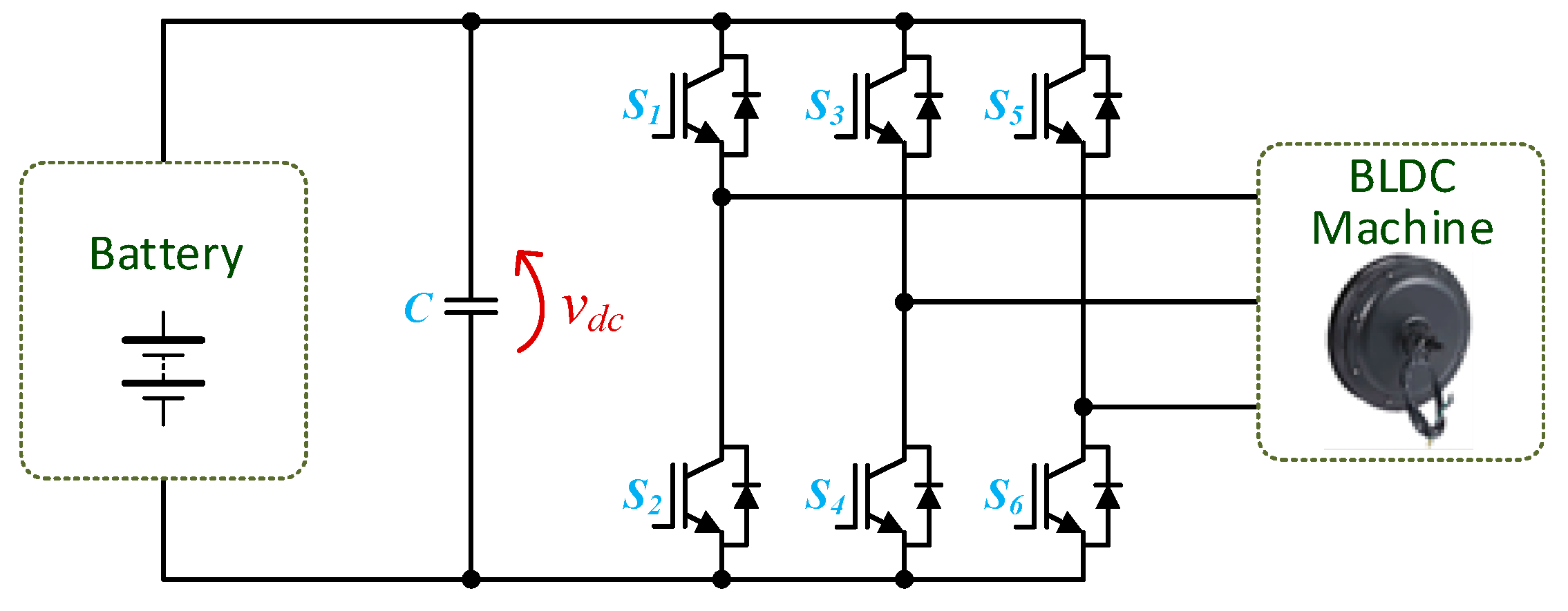
The three-phase voltage source converter shown in Figure 18b comprises six semiconductors and a capacitor bank in the dc link. Being a three-phase voltage source converter, it allows the production of three phase-to-phase voltages, where their amplitude, frequency and phase can be controlled. Hence, this converter is used in the vast majority of drive systems for three-phase ac electric machines.
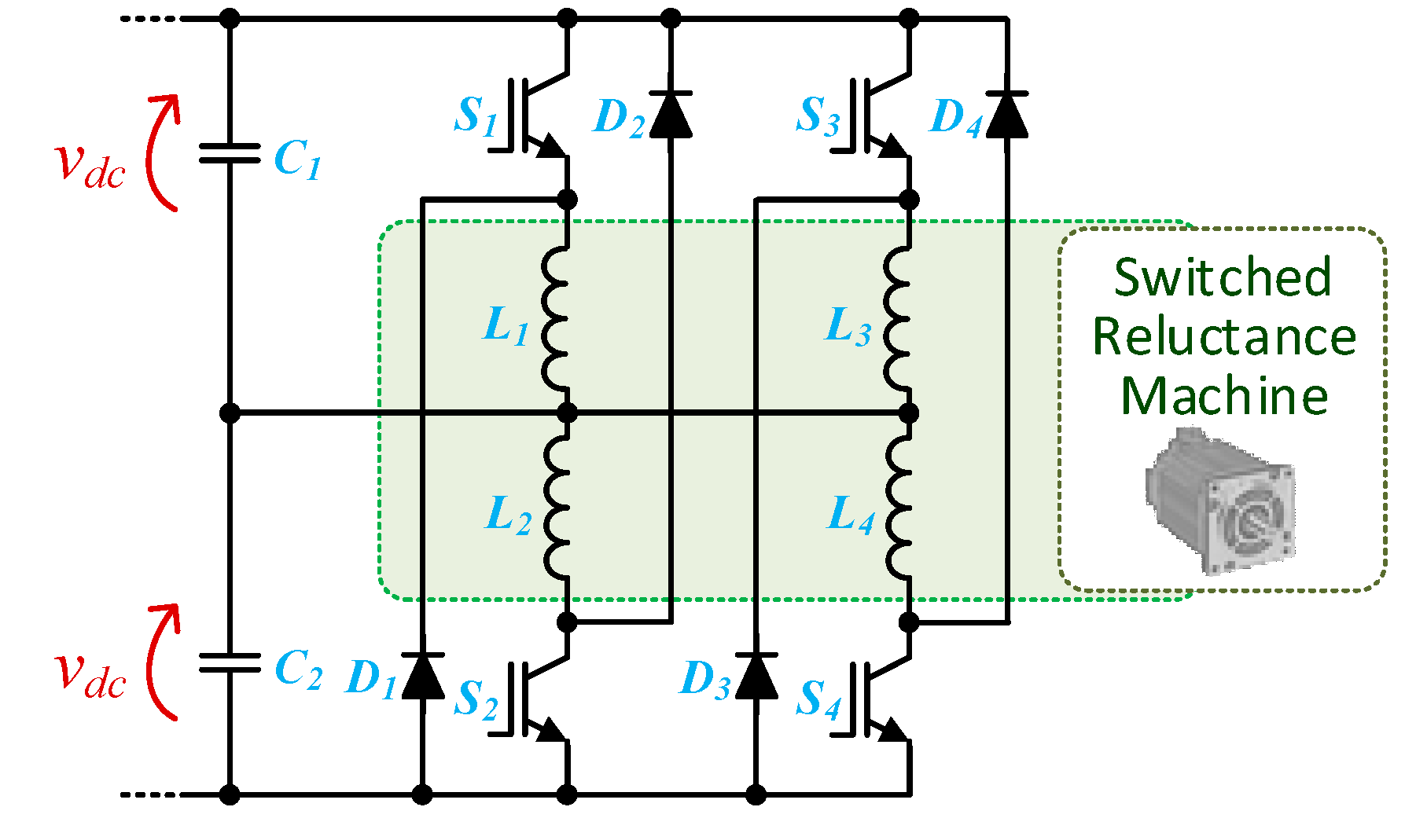
It should be noted that, despite being also used in an ac electric machine, the power electronics converters that drive the switched reluctance machines are different from the previously presented converter, mainly due to the fact that the torque produced by this type of electric machine is independent of the current direction. The topology presented in Figure 19 is the most flexible for the four-quadrant operation of the switched reluctance machine. The main benefit of this converter is the independent control of each phase. On the other hand, it presents the disadvantage of using two switching devices and two diodes in each phase of the machine. The power electronics converter presented in Figure 20 is denominated by a split-capacitor converter. This converter needs only one switching device and one diode per phase, however, it requires a split dc link voltage. This implies that the maximum voltage that can be applied to the electric machine stator windings is only half of the total dc link voltage. Furthermore, this converter is only applicable to switched reluctance machines with an even number of phases [214].
In low-speed applications, where a proper current control is desirable for all the operating power range of the electric machine, the classical power converter used for switched reluctance electric machines can be simplified, obtaining the power converter presented in Figure 21. This power converter is known as a Miller converter due to its creator and it is also named as a c-dump converter [214]. The main advantage of this converter is the use of n + 1 switching devices and n + 1 diode for n phases of the electric machine, contrarily to the previous converter, which uses 2n switching devices and 2n diodes per phase. On the other hand, the main drawback of this topology is related to high-speed operation, since it only uses one switching devices to control the common point of the electric machine phases [215].
As previously referred to, current source converters use an inductor in the dc link instead of a capacitor for storing energy, making the converter operating as a current source. In Figure 22 is shown a three-phase current source converter. The main advantages of this type of power converters, when used in EVs, are: (i) inherent short-circuit protection; (ii) the produced ac currents have lower high-frequency ripple; (iii) it is not necessary to connect antiparallel diodes to the fully-controlled switching devices; (iv) it is possible to obtain higher output ac voltages than the input dc voltage. However, this type of power converter also presents disadvantages compared to voltage source converters: higher volume and weight; higher risk of over-voltages and voltage spikes, as well as the necessity of using switching devices capable of blocking bipolar voltages—the reverse-blocking insulated gate bipolar transistor (RB-IGBT) is an example of such power semiconductor, which has the disadvantage of having higher conduction and switching losses than regular IGBTs, besides being more expensive. Alternatively to the use of RB-IGBTs, a diode can be placed in series with each IGBT, which also increases the overall losses and cost of the power converter [212,216,217].
As mentioned, EVs are related to a new and revolutionary type of vehicles, however, the conversion of conventional vehicles, based on ICEs, into EVs can be an attractive and low-cost solution for a transitory period. This process is a challenge that has become popular in the last few years. Some universities and research centers have been developing conversions of ICE vehicles to EVs. Examples of these conversions include an Opel Kadett by the University of Zagreb [218], a VW Lupo by the Eindhoven University of Technology [219], a Honda Civic by CREATE Lab of the University of Carnegie Mellon [220], a Porsche 914 by Massachusetts Institute of Technology [221], a Volvo 460 GLE by the Polytechnic Institute of Viseu [222], and a Jaguar E-Type by Jaguar itself [223]. The group of energy and power electronics (GEPE) of the University of Minho has developed a prototype of a plug-in EV that is called CEPIUM (Carro Elétrico Plug-In da Universidade do Minho), which can be seen in Figure 23. CEPIUM is a vehicle where the ICE was replaced by an electric machine. An axial flux PMSM is used due to technological advantages, namely high efficiency, low maintenance costs, and reduced size for the same power when compared with other types of electric machine. Everything necessary for the conversion was developed by the research group, including the power electronics circuits for the traction system and for the EVBC with G2V and V2G features [224,225].
Recently, several companies around the world have been specializing in the conversion of ICE vehicles to EVs. These companies have focused on the development of conversion kits for specific vehicle models and universal conversion kits that can be applied to any vehicle model. Examples of these companies include: ZEEV, from Portugal; Retrofuture, from France; EV Europe, from the Netherlands; EV West, from the United States of America; and Freedom Won, from South Africa. Moreover, this approach allows for a more sustainable transition from ICE vehicles to EVs, since it is based on the partial reutilization of parts, instead of the total replacement of conventional ICE vehicles, contributing to reduce the ecological footprint. The conversion of ICE vehicles to EVs gained some attention of the market and may represent a feasible solution in that transition.

2.4. Unified Systems for Traction and Battery Charging

Typically, an EV comprises two main power systems, one regarding the traction system and the other regarding the EVBC. By analyzing both systems, considerable similarities can be found in both power electronics topologies, specifically, in the converter that drives the electric machine responsible for the EV traction and in the converter responsible for the EVBC. Additionally, it should be noted that these two systems never operate simultaneously, thereby many topologies and control algorithms that aim to unify both power converters into a single one have been investigated targeting to reduce the volume, weight, and total cost of the system.
The first unified power converter was proposed by a partnership between the USA Department of Energy and NASA [226,227], followed by the patented proposals from Rippel and Cocconi in 1992 [228]. Since then, numerous topologies have been studied and proposed, where some exemplificative cases can be found in [229,230,231]. The diversity of topologies is large, including solutions based on split-phase winding machines [232,233], power converters based on voltage source [234] and current source structures [235], and with or without galvanic isolation [236,237,238,239].
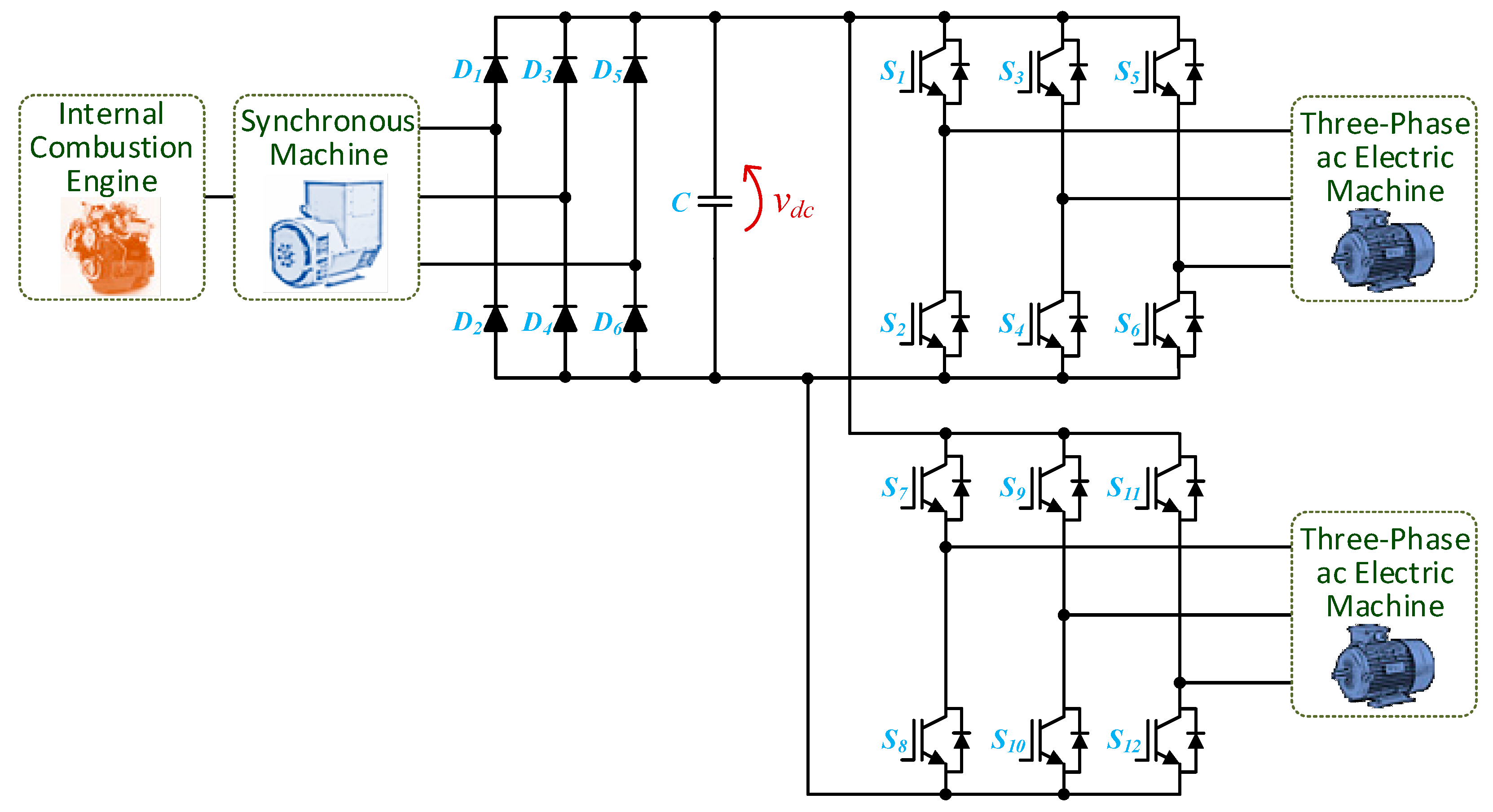
A simple topology that allows the unification of both power converters is shown in Figure 24. The main feature of this topology is the possibility to be applied to any type of three-phase ac electric machine, with or without access to all winding terminals, since the electric machine is disconnected from the power converter during the battery charging operation. In order to prevent harmonic current injection into the power grid and operate with a unitary power factor, it is necessary to add filters in series. These filters comprise three inductors with a high current rating, therefore being heavy and bulky, which is very disadvantageous considering their application in EVs [234,240].
Dusmez and Khaligh [241] proposed a topology similar to that previously presented, with the main difference being the fact that only two high current rating inductors are used instead of three. In this topology, the third inductor is attained with the series connection of two windings of the electric machine. As with the previous topology, this one allows fast battery charging operation through a three-phase power grid. Since the power converters are bidirectional, this topology allows the operation with extra functionalities, such as returning back to the power grid part of the energy stored in the EV battery.
In [237] is presented a topology of a unified system for fast battery charging using a transformer that is external to the EV, i.e., it is located in the charging station. This topology is similar to the two presented above, where the electric machine is disconnected from the power converter through a contactor. The transformer is located between the power converter and the power grid. This topology allows for galvanic isolation and the adjustment of the dc link voltage. Accordingly, the EV can only be charging in a specific location [237].
In 1994, AC Propulsion Inc. patented the topology which is in use in BMW Mini E electric car [234,241,242]. This topology allows bidirectional power flow, thus allowing additional operation modes, such as V2G and V2H. However, it does not allow fast battery charging to be performed, since it is not possible to establish a connection with a three-phase power grid. Moreover, it allows fast battery charging to be performed, since it is possible to establish connection with a three-phase power grid.
Figure 25 shows a three-phase topology using the electric machine windings as coupling inductors with the power grid [243]. It should be referred that a special type of ac electric machine must be used in order to accomplish this topology, i.e., an open-end winding electric machine, since it is necessary to have access to the six terminals of the stator windings. This topology presents a limitation in the battery charging mode. More specifically, if an asynchronous machine is used, the connection of the stator windings to the power grid will create a rotating magnetic field, which in turn will result in a torque that will force the electric machine to rotate.
Rambabu Surada et al. [244] proposed the topology that can be used with any type of three-phase ac electric machine for the traction system. This topology can operate in five operation modes: (i) boost-type converter, adjusting the dc link voltage from the battery voltage; (ii) buck-type dc–dc converter, charging the battery during regenerative braking operation; (iii) plug-in system, charging the EV battery from the power grid; (iv) independent single-phase power converter, in case of power grid fault; and (v) connection to the power grid, delivering back to the power grid some part of the energy stored in the EV battery. This topology does not allow fast battery charging.
In [239] is presented a topology that uses the midpoints of the machine stator windings to connect with the power grid. It has the advantage of being used as a fast battery charger. However, depending on the type of electric machine, the rotor can still rotate, making it necessary to implement a braking system for the electric machine when the battery charging operation is in process. The need to access the midpoints of the electric machine windings is a disadvantage of this topology, since it increases the complexity of the electric machine [229,239,245,246,247].
Figure 26 presents a topology of a unified system based on the connection of the power grid in the intermediate points of the split-phase stator windings [229,239,245,246]. Once again, the stator windings of the ac electric machine are used as coupling filters. The topology is based on two three-phase power converters that are connected to the winding terminals of each phase of the electric machine, making it possible to increase the voltage applied to the electric machine in traction mode [239]. The main advantage of this topology is the fact that it discards a contactor for interfacing the power grid. As in the previous topology, it is required the access to the intermediate points of the split-phase stator windings. There are other types of electric machine that can be used in this configuration, such as ac electric machines with two stators [232,239,248].
In [249] is presented a topology that uses the neutral point of the ac electric machine in order to connect to the power grid. It is not necessary to implement a braking system for the electric machine during the battery charging operation because the power flow is unidirectional and it does not produce torque [249]. Omar Hegazy et al. proposed a bidirectional single-phase unified topology in [238]. This power converter presents four operation modes: (i) electric machine driving, transferring energy from the dc link to the electric machine; (ii) three-phase active rectifier, transferring energy from the electric machine to the dc link; (iii) battery charging from a single-phase power grid; (iv) returning back to a single-phase power grid part of the energy stored in the batteries. Ivan Subotic et al. [230] proposed a topology that uses a five-phase ac electric machine. A five-phase traction system presents a good compromise between two requirements that are usually opposed, namely fault tolerance and system complexity. This topology needs a bidirectional dc–dc converter to interface the battery and the dc link. Saeid Haghbin et al. presented a topology based on a split-phase PMSM with two power converters, namely one per each set of windings. The EVBC is bidirectional and non-isolated, and it does not allow fast battery charging operation [233].
In [231] is presented a unified system for a switched reluctance machine. The power converter and the winding inductances of the electric machine combined behave as an interleaved boost-type dc–dc converter. Other proposals regarding unified systems for this type of electric machine can be found in [250,251,252,253,254].
Figure 27 shows the topology of a unified system based on a current source converter. This topology allows charging the battery from regenerative braking without the need for inverting the dc link current [235]. In this solution, either the ac electric machine (traction mode) or the power grid (battery charging mode) is connected to the power converter at each time, depending on the KM1 position. The dc link inductor is interfaced with the EV battery through an asymmetrical h-bridge converter, allowing the dc link current to be adjusted.

2.5. Summary

Regarding EV battery charging systems (EVBC), Table 3 presents a comparison based on the topologies presented in item 2.1, namely, on-board and off-board EVBC. With the objective of establishing a comparison in terms of main features, it was considered the multilevel characteristic (i.e., establishing that the topology is considered as multilevel when the voltage levels are higher than 3), the interleaved characteristic (i.e., with more than two parallel paths for current), isolation (i.e., mainly considering the dc–dc power converters, since it is not usual to have isolation on the ac-dc power converters), and bidirectional power flow (i.e., the possibility of the EVBC to operate in G2V/V2G mode).
Table 4 shows a comparison among the unified systems for traction and battery charging topologies presented in item 2.4. The comparison takes in consideration metrics such as the ability to perform fast battery charging, capability of bidirectional power flow, galvanic isolation, the necessity for external inductors, and the need for special electric machines with access to additional winding terminals. It is considered that all the presented topologies allow slow battery charging. Moreover, the analyzed three-phase topologies also allow a single-phase connection.

3. Power Electronics for Railway Systems

This item presents a review of power electronics for railway systems, showing the importance of power electronics converters in the area of electrified railways, in which these converters can be installed outside the train for the purpose of power quality improvement, or to interface between the high voltage three-phase power grid and the medium voltage single-phase traction power grid. On the other hand, power electronics converters can also be installed inside the train for traction and regenerative braking applications. Additionally, special power electronics applications in railway systems are also presented in this item. Taking into consideration the existing opportunities in the railway industry, not only in the development of the electric train itself, but also on the aforementioned topics, there is a strong investment in technological development for electrified railway systems. Subsequently, various solutions based on power electronics converters are also presented in this item.

3.1. Power Quality Compensators

Power quality deterioration has direct adverse impacts either on the power grid, including the electric locomotive itself, or on the signaling and communication system between trains. Power quality deterioration will result in higher operating costs of electrified trains, as well as in polluting the three-phase ac power grids with high total harmonic distortion and negative sequence components [255]. In order to overcome the power quality deterioration, power compensators based on passive components is a technology used in the last decades, and even nowadays. However, these passive compensators are not able to follow the fast-dynamic changes of non-linear loads, which is the case of the traction load (electric locomotive). Therefore, there is a need for dynamic compensators that follow the non-linear dynamic changes, and power electronics compensators serve this purpose [256,257,258,259]. In this context, a possible solution is the use of a static synchronous compensator (STATCOM), which consists of a three-phase voltage source converter, coupling power transformer and filter inductors installed on the three-phase ac power grid. This type of solution allows reactive power exchange between the STATCOM and the three-phase ac power grid. For example, in Japan, five sets of 34 MVA to 60 MVA STATCOM devices are available in the Tokaido Shinkansen high-speed railway, which links Tokyo and Shin-Osaka stations [260].
Figure 28a depicts the STATCOM device connected in parallel with the three-phase ac power grid. This parallel connection signifies that the STATCOM can be connected or disconnected without disturbing the operation of the traction substation. Consequently, the robustness and readiness of the railway substation will not be affected by the STATCOM operation [261]. Moreover, this device does not require an internal power supply, meaning that the STATCOM has a neutral contribution in terms of active power. That is, except by the negligible STATCOM internal power losses, STATCOM will not consume or provide active power to the three-phase ac power grid, and its main objective is solely to exchange reactive power with the three-phase ac power grid in order to improve power quality. Consequently, the STATCOM exchanges the instantaneous reactive power among the phases of the three-phase ac power grid, thus acting as a source of reactive power [262].
Another possibility is to consider a power converter connected to the single-phase traction power system (TPS), where the rail power conditioner (RPC) is used for the purpose of power quality improvement in the ac electrified railways. The RPC structure contains two single-phase back-to-back converters with a single dc link in between and two coupling transformers, as shown in Figure 28b [263]. The STATCOM device is a three-phase converter, whereas the RPC is composed of two back-to-back single-phase converters. Each converter is connected to a load section through a buck-type coupling transformer. The first proposal of a 60 kV, 20 MVA RPC for Tohoku Shinkansen railway in Japan was implemented in 2004 [264]. The implemented RPC at that time was based on multilevel converters and a Scott power transformer. Another project was implemented in March 2009, where RPC systems with gate commutated thyristors were installed in four substations of the Tokaido Shinkansen in Japan: Shimizu substation, Shin Kikugawa substation, Shin Biwajima substation, and Ritto substation. Detailed information on that project can be found in [265].
New power electronics compensators have the advantage of scalability and modularity in which modular multilevel converter (MMC) is adopted to replace the conventional two-level converter. The MMC advantages are quite numerous, such as the scalability to different power and voltage levels, reliability to guarantee continuous operation even if few submodules stop working, and reduced grid-connected filter size, due to the good quality of the synthesized waveforms [266]. Figure 29 shows the RPC based on the MMC system. When compared to the conventional RPC system presented in Figure 28b, buck-type coupling transformers used to interface between the RPC and the single-phase TPS can be dispensed with [267].

3.2. Power Management Converters

Power electronics converters in electrified railways are not only related to the application of power quality improvement, but also to power management applications between traction substations, or between the three-phase ac power grid and the single-phase TPS. In that regard, this item presents two relevant power electronics solutions. The first is an interface converter between the three-phase ac power grid and the single-phase TPS, as shown in Figure 30 [256]. This interface is useful to perform frequency conversion when the single-phase TPS frequency is different from the three-phase ac power grid frequency. For instance, this interface converter can be an appropriate solution to link the 50 Hz three-phase ac power grid with the 16.7 Hz single-phase TPS [258]. On the other hand, this power converter presents the single-phase traction load as a balanced three-phase load to the power grid. Moreover, all the reactive power required by the traction load can be provided by the interface converter, which is essential to obtain a unitary power factor for the three-phase ac power grid. Moreover, the energy resulting from regenerative braking can be stored in batteries. This interface converter prevents harmonic content generated by the locomotives passing from the single-phase TPS to the three-phase ac power grid. The main disadvantage of this converter is that it should be rated to endure the full load power. In some references, this solution is called a static frequency converter [256,258].
Another interface converter between two traction substations is presented in Figure 31. This converter is used to interface between two phases (with different out-of-phase angles) for the purpose of power transmit from two substations instead of only one substation [263]. In other terms, it is possible to shift the active power from one substation to another. Additionally, reactive power can be provided by the interface converter. This is useful to extract a higher amount of power during the peak load demand, avoiding overloading conditions of traction substations and allowing a greater flow of locomotives by increasing the power capacity of the overhead catenary. An interface converter located between two traction substations, which is commercialized by Hitachi, Japan, is presented in [268]. The system started the operation in 2015 and is designed to shift active power from one substation to another, including the energy resulting from the regenerative braking of the trains. It is worth mentioning that this interface converter between two traction substations is only able to transmit power between traction substations and has no ability to accomplish power quality improvement [263].

3.3. Traction and Regenerative Braking Converters

Power electronics converters are essential to drive traction machines for the rail transport system, including the high-speed ac electrified railways and the light rail powered by dc overhead catenary line. The configurations of the TPS with regenerative braking are shown in Figure 32 and Figure 33 for the ac and the dc overhead catenary lines, respectively. In the primary converters ac-dc and dc–ac it is important to have three-phase ac currents, thus powering the traction machines. The primary converters are important to perform the power conversion and to use the power resulting from the regenerative braking of the three-phase traction electric machines. In light railway applications, such as suburban and regional trains, the dc link voltage is selected in the range of 1500 V dc, whereas in high-speed ac railway the dc link voltage is selected in a range between 1500 V and 3600 V [263].
The auxiliary converters are used to supply the train auxiliary loads. There is a dc–ac auxiliary converter that is linked to the main dc link voltage, and its output is connected to the main transformer for auxiliary loads. The output of the dc–ac auxiliary converter is a three-phase 380 V supply, which is used to feed, for instance, the on-board fluorescent lights, cooling fans, electric outlets, and air conditioning [269]. The traction system is configured with external batteries connected to an auxiliary dc–ac power converter. When the train is passing through a neutral section, conventional ac trains may suffer shutdowns due to instantaneous catenary line power interruptions. The solution proposed in [269] can use the energy stored in batteries to avoid shutdowns of the auxiliary power supply. The batteries are charged by the regenerative braking power or by the power from the catenary line. When the batteries are installed directly near the main dc link, they can be used to power the train when passing through a neutral section.
Table 4 presents the power electronics technologies used in the propulsion system of electric locomotives. Usually, a propulsion system for dc traction power supply is simpler and slightly cheaper than the one for an ac traction power supply, since the costs of power transformers in the dc traction power supply can be saved. On the other hand, only one stage of power conversion is required in the dc traction power with dc electric machines (dc–dc converter), e.g., tram lines, which makes this solution the cheapest among the other propulsion systems [270].
As shown in Table 5, power electronics converters are essential to perform power conversion with different frequencies and amplitudes. For instance, when dc traction machines are utilized, dc–dc converters are crucial to adjust the dc voltage values. On the other side, dc–ac converters are indispensable to drive the ac electric machines by changing the voltage frequency and amplitude, known as variable voltage variable frequency drive [270,271]. Future converter technologies are likely to utilize SiC devices for more efficient traction systems, besides the benefits of higher temperature operation capability and the possibility of manufacturing smaller and lighter power converters without transformers. However, there are still issues to be solved in terms of both costs and technology, provided that SiC devices still have poor global ease of procurement and high costs [271].

3.4. Special Power Electronics Applications in Electrified Railways

Power electronics converters for special applications in electrified railways are quite numerous. Most of the new railway lines are equipped with energy storage systems, such as batteries, which are essential for continuous electrical power feeding when passing through non-electrified sections. On the other hand, energy storage systems are important for enabling the recovery of energy from regenerative braking [272]. To achieve the highest profits, power electronics converters enable on-board or even off-board storage applications. In both cases, the power converter has to draw the maximum possible power over time from renewable energy sources. In this context, energy storage system applications for railway transportation have been presented in [273]. Moreover, the possibility of a photovoltaic power supply path from the station roof to the train has been presented in [274].
In the last few decades, magnetic levitation technology has universally emerged as a sustainable and viable alternative to conventional on-wheel rail technologies. However, the development of this technology has been related wholly to that of power electronics since they have an integrated levitation and propulsion system. In this type of application, power electronics converters are used to regulate the magnet current, known as suspension choppers [275]. Hyperloop and Maglev technologies are both based on the train’s levitation. A detailed explanation of these two technologies is introduced in [276].
Despite its lower electrical efficiency and other technical difficulties, IWPT technology (Section 2.2) has also been explored in the electrification of railways [277], as a possible alternative for contactless catenary-free systems [278]. Power rectifiers, resonant inverters and efficient magnetic coupling systems are required for the transmission of power using high-frequency currents. In that regard, a high-speed prototype that was developed in South Korea, with 1 MW WPT, is presented in [279].

3.5. Summary

The railway market requires traction power systems that are more energy-efficient and respond to diverse customer needs. In this section, some of the power electronics converters that can be used for railway applications were shown. These power converters contribute to solving some power quality phenomena in the three-phase power grid. In that regard, RPC and STATCOM solutions were presented to overcome three-phase current imbalances, reactive power, and harmonic contents. On the other hand, power management converters could help to increase the loading capacity of traction substations. Additionally, power electronics solutions for regenerative braking and traction machine drive in ac and dc traction machines were also presented. Applications of power electronics converters for fixed applications (power electronics converters installed in the traction substations) and moving applications (power electronics converters installed in the electric locomotives) were presented, considering future trends for superior performance and increased resilience of railway systems. Table 6 summarizes the main capabilities of the power electronics converters presented in this section for the purpose of railway fixed applications.

4. Power Electronics for Other Types of Electric Vehicle

Besides its terrestrial variant, the transportation sector includes also other types of travelling, such as maritime and aerial. In fact, the electrification process that is being carried out in road vehicles is also noticeable in other transportation sectors, mainly due to the same factors that motivate the electrification of road vehicles, i.e., regarding both environmental and economic concerns. Therefore, this section introduces a review of power electronics for other types of EV, not only including maritime and aerial means of transportation, but also considering other types of terrestrial vehicle besides the vastly used automobile. Accordingly, this section includes ships, aircraft, trucks, buses, pallet trucks and forklifts, scooters, bikes, and small EVs. It should be noted that the power electronics structure used in the traction system of these types of EVs is very similar to that of road vehicles, i.e., the same topologies of power converters are used, differing essentially in the power rating, which can be higher, for instance, in the case of electric ships and trucks, or lower, such as the case of electric bicycles and scooters.

4.1. Electric Ships

Besides terrestrial locomotion, maritime transportation is also undergoing an electrification process. In fact, since the 19th century electric power systems have been installed on ships [280]. Concerning the powertrain level, the utilization of electrical propulsion systems on ships offer several advantages over diesel propulsion engines and gas turbines, such as superior dynamics, i.e., start, stop and speed variations, less fuel consumption, less mechanical vibration (and, therefore, a higher comfort for the passengers) and a higher flexibility for adding electric machines to the powertrain [281]. Moreover, an electric ship can be seen as an islanded microgrid [282,283]. In [284], the utilization of fuel cells is investigated in the electric propulsion of ships, aiming to reduce the emission of greenhouse gases, volatile organic compounds and particulate matter, which are highly related to the exhaust of non-electric ships. In [285] is studied a design of electrical distribution systems for ships and oil platforms, taking into consideration control systems and protections and a zonal distribution to improve modularity, being considered both ac and dc systems. In [286] is proposed a hybrid energy storage system based on a battery and a superconducting magnetic energy storage element in order to improve the stability of dc power systems of fully electric ships, being used a two quadrant buck-boost dc–dc converter for the battery and an asymmetrical h-bridge dc–dc converter for the superconducting magnetic energy storage element. In [287] is presented a conventional structure of an on-board ship power system (Figure 34), having been studied the power flow in the electric power system with energy storage and energy management systems, comprising ac, dc and hybrid ac-dc power grid architectures.

4.2. Electric Aircraft

Aerial transportation has also been a target of research towards electrification, not only in terms of powertrains but also in subsystems that traditionally use hydraulic, mechanical and pneumatic power, aiming to reduce emissions, fuel consumption and operating and maintenance costs. This paradigm has been referred to as the “more electric aircraft” [288,289]. In [290] is presented a starter generator system for electric aircraft based on a three-phase three-level neutral point clamped dc–ac converter, with a higher power density being achieved compared to conventional starter generator systems without using power electronics converters. In [291] is presented the design of an integrated modular machine drive for electric aircraft based on a five-phase PMSM machine and a SiC-based five-phase five-leg dc–ac traction converter (Figure 35), and [292] studied a design method for a cooling system to be used on electric aircraft powertrains. In [293] is analyzed the regenerative braking operation of an electric taxiing system, i.e., when an aircraft moves by its own on the ground instead of in the air to move, for instance, between the runway and the hangar. In [294] is studied a fault management design for electric aircraft, while in [295] are analyzed the effects of fault currents in aircraft electric power systems both at the electrical and thermal levels. An optical sensing method for detecting partial discharges in higher voltage (above 1 kV) electric aircraft is proposed in [296], and [297] investigated the conduction of electromagnetic interference in more electric aircraft microgrids.

4.3. Electric Trucks

Electric trucks consist of a terrestrial means of transportation, despite not having the same well-defined and planned routes as other means of transportation such as buses, depending on the type of truck. For freight transportation road trucks, whose routes can be planned, Siemens has developed a solution based on pantographs and hybrid trucks, which is called eHighway [298]. Pilot projects have already been implemented on public highways in Sweden and Germany, with Siemens referring to this technology as the most cost-effective solution regarding electric trucks despite the required investment. In [299] is proposed a conceptual model for enhancing the eHighway system, aiming to endow it with autonomous driving. In [300] is proposed an energy management strategy for hybrid trucks, aiming to maximize the batteries lifetime while also reducing emissions. Besides freight trucks, the electrification of trucks is also researched regarding mining applications. In [301] is presented a model of a trolley assist system for mining trucks, which allows the machines of the trucks to be supplied by engaging them on the trolley lines. This system is based on three-phase three-leg active front end ac-dc converters and helps to increase the drive speed on uphill trajectories while economizing fuel, besides allowing to perform regenerative braking on downhill trajectories. In [302] is studied the stress of mechanical and electrical components in electric mining trucks, both for uphill and downhill operations. In [303] is proposed an energy-saving control strategy regarding the repetitive start-up operation of mining trucks, since their normal operation consists of short distance travels and continuous start and stop, which is highly energy consuming. At the powertrain level, in [304] is proposed a modular three-port traction converter based on four winding switched reluctance machines for plug-in hybrid electric trucks. This converter is based on two h-bridges connected in a cascaded way, i.e., connected to each other by the ac side, and the dc negative rail is common to both h-bridges. The traction converter can be connected to a battery, a generator and also to the power grid, i.e., the proposed system is a unified system. Moreover, the operation of the converter allows the machine stator windings to be connected either in series or parallel. Figure 36 presents a traction system for an electric truck based on two three-phase ac electric machines.

4.4. Electric Buses

The electrification of buses is one of the most promising migrations towards electric mobility, since buses represent a type of public transportation with well-defined and planned routes, easing the battery charging necessity and scheduling. Electric buses are already being used in cities worldwide and their adoption is continuously growing [305,306], with many scheduling approaches and models being proposed in the literature in order to maximize energy efficiency [307,308,309]. A case study regarding the electrification of a bus depot in London is presented in [310], with reported savings in both financial (£1.7 million over a 14 year lifetime) and environmental (48,200 tons of CO2 between 2019 and 2050) aspects, when compared to traditional diesel buses. In [311] is presented a scheduling approach for a single depot comprising a mixture of electric and diesel buses, aiming to minimize the operating cost and carbon emissions using constraints of time between travels and driving range of the electric buses. At the powertrain level, in [312] is studied the design of an energy management system for a hybrid electric bus and in [313] is studied the energy management system of a dual-machine fully electric bus. Due to their fixed routes, electric buses are especially predisposed to the implementation of IWPT functionalities. As mentioned previously in this paper (Section 2.2.7), a system termed OLEV was proposed by KAIST in South Korea, which consists of an electric bus that is supplied wirelessly through a coil embedded in the road [314]. This reduces the need for using large battery banks, which is advantageous since batteries are one of the most expensive parts of EVs and the main reason for them to have a lower driving range compared to ICE vehicles. In [315] is presented an electric powertrain for electric buses based on a hybrid energy storage system. Besides the battery bank, the proposed solution also includes a super capacitor bank to store the energy collected upon the regenerative braking system (Figure 37).

4.5. Electric Pallet Trucks and Forklifts

EVs can also be used for industrial applications. For instance, in [316] are proposed two unified systems for industrial EVs, namely a pallet truck and a forklift, both encompassing galvanic isolation between the power grid and the battery (Figure 38). The pallet truck is powered by a 1.5 kW dc electric machine, using an isolated cuk dc–dc converter, while the forklift is powered by a 6 kW wound rotor induction machine, with the rotor windings being connected to the power grid and the stator windings connected to the traction/charging front-end power converter. Also, regarding forklifts, in [317,318] is studied the design and implementation of switched reluctance machines for their traction system. The energy efficiency of electric forklifts is studied in [319] for induction machines and in [320] for PMSM, with the energy efficiency of both types of electric machines being compared in [321]. At the energy storage level, in [322] is presented the design and control of a phase-shift full-bridge isolated dc–dc converter for the on-board EVBC of an electric forklift. Hybrid energy storage systems for electric forklifts are presented in [323] based on batteries and ultracapacitors, in [324] based on batteries and fuel cells, and in [325] based on fuel cells and ultracapacitors, using no standard batteries. An electric energy recovery system for an electro-hydraulic forklift is studied in [326]. Besides full-electric forklifts, in the literature can also be found research regarding hybrid forklifts, with the hybridization of diesel forklifts being studied in [327] and simulation and experimental validation of a hybrid forklift being presented in [328].

4.6. Electric Motorcycles/Scooters

In developing countries, one of the most used means of transportation is the motorcycle, not only because it has affordable purchase cost but because it allows for more flexible mobility, with the electric approach being a promising solution [329,330]. The replacement of ICE motorcycles by electric motorcycles and consequent environmental and energy savings, in different and specific parts of the world, is referred to in several works in the literature, as demonstrated in [331,332,333,334]. The impact of electric motorcycles and scooters in the distribution network is addressed in [330]. In [335], a prototype of a motorcycle with electric propulsion is designed and developed, where a 7.4 kW BLDC machine is driven by a three-phase voltage source inverter. In [336] is presented a comprehensive design of a controller for a BLDC machine, providing an electromagnetic brake and kinetic energy recovery. In [337] is presented a solution for measuring the rotor position of the BLDC machine in order to enable the implementation of vector control algorithms such as field-oriented control. In [338,339], technologies for electric motorcycle traction systems are proposed, where the BLDC machine type is used. In [340], a 2003 Honda CBR600RR motorcycle was converted to electric, where a battery bank of 155 V at 40 Ah has been designed and is used an ac electric machine that allows a prototype with an estimated maximum power of 60 HP. In [341], an electric superbike race demonstrates that electric motorcycles can race at high speeds on demanding tracks.
One means of transportation that has also been gaining interest in urban areas is the electric scooter, which is framed in the group of light EVs. This has been implemented in several countries as a vehicle-sharing system, aiming to alleviate the traffic mostly caused by cars [342]. The majority of these electric scooters are not human-assisted, i.e., the power applied to perform the motion comes entirely from the electric machine. In [343] is proposed a kick assisted electric scooter, which is a type of electric human-powered hybrid vehicle. The main difference between an assisted and a non-assisted electric scooter is very similar to the difference between electric motorcycles and bicycles. In [344] is proposed an electric scooter with G2V, V2G, V2H and energy-harvesting functionalities (Figure 39), and in [345] is proposed a hybrid energy storage system for an electric scooter based on ultracapacitors and IWPT, reaching an overall efficiency of 86.4%.

4.7. Electric Bicycles

The bicycle plays an important role in today’s society. It is an environmentally friendly vehicle that is economically accessible to a wider range of the population, representing a good means of transportation for short distances, such as in urban areas. Bicycles contribute to reducing energy consumption, air pollution, city traffic and, in addition, their regular use improves the health of the cyclist. On the other hand, it does not undergo taxes, parking costs, driving license or high maintenance service costs in comparison with ICE vehicles.
However, on long journeys, the bicycle has disadvantages in terms of exhaustion of the cyclist. In [346,347] is presented an effort control system for cycling, which contributes to promote the user’s mobility and physical health. In view of the disadvantages of traditional bicycles, the development of electric bicycles has begun, generally known as e-bicycles or e-bikes. In some designs the bicycle can be propelled solely by its electric powertrain, in others, electric assistance is added to pedaling, making it possible for less-fit individuals to ride on steep terrains and for longer distances, thus extending the usefulness of the bicycle [348,349].
The first electric bicycle was patented in 1895 by Ogden Bolton Jr. It used a six-pole dc hub machine mounted in the rear wheel and had no gears, consuming up to 100 A from a 10 V battery [350]. Over the years, new designs for electric bicycles have emerged. However, the greatest evolution occurred in the 1990s, due to the technological progress of electric machines, power electronics controllers and sensors, as well as batteries. The evolution of battery technologies allowed for greater energy storage capacity, reliability and robustness, enormously contributing to the popularization of the electric bicycles [351].
Nowadays, electric bicycles are equipped with BLDC machines (Figure 40), but there are also electric bicycles with brushed dc electric machines and switched reluctance machines [352,353,354].
Normally, the machines for electric bicycles are named according to the place where they are connected: hub-drive or mid-drive machines. The hub-drive machine is placed in the front or rear wheel, more specifically on the wheel hub. The mid-drive machine is placed directly between the pedals, what ensures a low and mid-placed center of gravity [355,356].
Recently, control systems were developed to adjust automatically the effort control of the cyclist, based on the use of an electric bicycle and a smartphone. In accordance with the Directive 2002/24/EC of the European Parliament and of the council of 18 March 2002 relating to the type-approval of two or three-wheel electric machine vehicles, bicycles with pedal assistance are equipped with an auxiliary electric machine whose maximum continuous power is 0.25 kW. The controller will reduce progressively the power and cut it off if the speed reaches 25 km/h, or if the cyclist stops pedaling [356]. These systems allow people with different physical conditioning to ride together in the same track, where each member can choose the adequate electric machine assistance level [357,358,359].
In the current market, the diversity for electric bicycles is enormous, existing mountain bicycles, folding bicycles, cargo bicycles and urban bicycles, where the cyclist has a great choice for buying. In mountain bicycles, a large number of companies already produce electric bicycles. The RENOWATT 4.1 model of Coluer company is an example of a mountain bicycle. It has full suspension and uses an electric machine to provide assistance to the cyclist when he rides up to a speed of 25 km/h. This electric machine has a nominal power of 250 W, a maximum torque of 70 Nm and a nominal voltage of 36 V, adding 2.88 kg to the weight of the bicycle. It is powered with a lithium-ion battery with a nominal capacity of 504 Wh (36 V, 14 Ah) [360].
However, many people prefer to ride around the city or just as a mode of transport to reach work. In this case, the type of bicycle mentioned above is not the most suitable for this type of cyclist. The urban bicycle type is more adequate, with one example being the ELOPS 900 E. It has a BLDC machine in the rear wheel with a power of 250 W and a maximum torque of 30 Nm to assist the cyclist. The electric machine is powered by a battery with a capacity of 418 Wh (36 V, 11.6 Ah) and a range of 40 km to 70 km, depending on variables such as the weight of the cyclist, the selected assistance mode, and the slope of the terrain.

4.8. Other Small Electric Vehicles

Besides the previously mentioned types of EV, there are also some smaller EVs, i.e., with lower operating power. In the literature can be found power electronics solutions regarding the energy storage systems of small EVs, such as a system based on batteries and ultracapacitors [361], a two-stage battery charger with a power decoupling cell [362], based on a modified bridgeless boost-type front-end power factor correction converter and a phase-shift full-bridge isolated dc–dc converter, and a multi-input single-output dc–dc converter for small aerial vehicles [363], capable of interfacing batteries, ultracapacitors and fuel cells. The types of small EVs analyzed in this section are golf carts, Segways, Tuk-Tuks, step scooters and wheelchairs.
Similar to road vehicles, the first golf carts to appear were electric, with gasoline-powered golf carts appearing later. However, contrary to what happened with road vehicles, the electric variant has always been more popular due to gasoline rationalization in the 1950s in consequence of World War II, when golf carts were experiencing their early growth, besides offering more safety due to slower speeds than the gasoline-powered golf carts and also due to lower noise and no emission of pollutants. In [364,365,366,367] are presented implementations of solar-powered electric golf carts, which, besides the battery, are comprised by photovoltaic solar panels in their rooftop, with a buck-type dc–dc converter being used to interface the photovoltaic solar panels with the battery. In [368] is studied a hybrid energy storage system for a golf cart, being composed by batteries, fuel cells and ultracapacitors, with only one dc–dc converter being used, namely a simple boost-type topology. In [369] is presented the design of an induction machine especially conceived for use in the traction system of a golf cart.
The Segway is a type of EV designed for a single person, being a self-balancing low-power two-wheel EV. It was invented in 2001 by Dean Kamen [370]. In this type of EV, the employed electric machines are based on in-wheel machines, since the vehicle itself is only physically composed of two wheels intermediated by a platform, as well as a shaft in order for the user to travel safely. In [371] is presented the design of a Segway from the point of view of mechanics, fabrication, powertrain and electronics, and [372] analyzes in detail the mathematical model and control system of this type of EV. The design and development of Segway prototypes can be studied in [373,374,375].
The TukTuk is a three-wheeled motorized transport with a cabin, dedicated to the transport of passengers or goods, widely used in developing countries. In view of environmental concerns, maintenance and cost of use, this means of transport has an electrical homolog which can be found in the literature by e-Tuk-Tuk, Easy Bike, bicitaxis, rickshaws, among others [376,377,378]. Usually, these EVs contain a BLDC machine with a power rate of around 1.1 kW [379]. In [380] a 1 kW battery charger is proposed to charge the electric Tuk-Tuk batteries from the power grid.
The electric wheelchair is also a type of small EV, and it can be indispensable equipment for senior and disabled people. A review in terms of speed, traction, suspension and stability control for electric wheelchairs is reported in [381]. In [382] is presented the conversion of a mechanical wheelchair to an electric one, and in [383] is presented an all-terrain wheelchair, which is capable of navigating through obstacles, such as stairs and ramps. An electric power assisted wheelchair is presented in [384] with the purpose of reducing battery utilization. At the traction level, a torque distribution algorithm for the two wheels of an electric wheelchair is presented in [385], a differential drive based on BLDC machines is presented in [386], as shown in Figure 41, and the design and implementation of a spherical induction machine for electric wheelchairs is presented in [387]. The regenerative braking operation concerning electric wheelchairs is studied in [388,389], based on boost-type and buck-boost unidirectional dc–dc converters, respectively. The design and implementation of a solar power integration in an electric wheelchair, with a solar photovoltaic panel acting as a roof for the wheelchair, is presented in [390], and the battery charging operation via IWPT for electric wheelchairs is studied in [391], with the primary circuitry being based on a full-bridge inverter and the secondary based on a diode full-bridge ac-dc converter and a buck-type dc–dc converter.

5. Conclusions

Around the world, environmental issues are perceived as a priority topic, with the transport sector going through a technological revolution towards sustainability. Specifically, electric mobility is globally identified as the main alternative to transport based on non-renewable polluting fuels, and it is being increasingly supported by the various models of electric vehicles (EVs) currently produced by the automotive industry. Regardless of the vehicle model or type, the common basis to support electric mobility is power electronics. Throughout this article, several power electronics technologies for electric mobility are presented.
Regarding EV battery chargers (EVBC), both wired and wireless power transfer technologies are addressed. A review of power electronics converters that can be used for on-board and off-board EVBC is presented, covering the main topologies that can be used in the front-end and back-end power stages. Some developed laboratory prototypes are also presented, including on-board and off-board EVBC, along with illustrative experimental results obtained for the main operation modes. As demonstrated, both on-board and off-board EVBC are fundamental in supporting the integration of EVs into the power grid, presenting innovative features far beyond the simple charging process, e.g., bidirectional systems allow the exchange of active power with the grid, and also other features, such as the operation in isolated mode or the possibility of contributing to improving the electrical power grid quality. In this context, for selecting the more interesting power electronics topologies for on-board or off-board EVBC, the key features that should be considered are: the multilevel and interleaved characteristic for reducing the coupling passive filters; The galvanic isolation between the EV battery and the power grid, guaranteed by the dc–dc back-end converter; The four-quadrant operation to ensure that the bidirectional power flow is possible (allowing operation in G2V, V2G, V2H, and other modes). Still regarding EVBC, some solutions based on dc–dc converters to provide power to the auxiliary battery from the EV battery are also presented. Regarding traction systems, a brief presentation of electric machines used for the EV propulsion, as well as the electric machines that equip commercially available EVs, was made. From these electric machines, permanent magnet synchronous machines (PMSMs) and three-phase induction machines dominate the applications in EVs, while other electric machine technologies are emerging alternatives (e.g., reluctance machines and hybrid reluctance permanent magnet machines). Depending on the electric machine used, different drives and controllers may be necessary. Drive systems consist of solutions based on power electronics that are capable of acting on the voltage, current, and frequency supplied to the electric machine windings. The unification of both the power converters of the traction system and the EVBC is also presented. This unification is possible because, except in the case of dynamic inductive wireless power transfer, these two systems are not required to operate simultaneously. The unified system allows a reduction in volume, weight and total costs when compared with the traditional solutions (traction and battery charging as separated systems), also allowing additional operation modes that comply with the paradigm of smart grids. Regarding the power level of unified systems for EVs, increasing the number of phases or the number of windings of electric machines (i.e., the use of open-end split winding electric machines) leads to an increase in the number of power semiconductor legs employed in the power converters, permitting an operation similar to an interleaved configuration, which is one of the main solutions to reduce the current stress and increase the power level of a power electronics system.
Additionally, other types of vehicle, such as railway vehicles, ships, aircraft, trucks, buses, forklifts, scooters and bicycles are also targets for electrification, and were also addressed in this paper. For instance, power electronics converters in electric railways are indispensable, and comprise a significant part of the railway electrification system, with the objective of improving power quality, efficiency and resilience, both for fixed applications (in traction substations) and for moving scenarios (in electric locomotives). These converters can be installed at the medium-voltage level, outside or inside the locomotive, for different applications. In that regard, power quality compensators, power management converters and power converters for traction and regenerative braking have been addressed in this paper. Public electric transportation, such as electric buses and railway vehicles, together with electric trucks, are reported in the literature to be more economical and to reduce environmental damage, when compared to their traditional internal combustion engine counterparts. Lightweight personal EVs, such as electric bicycles and scooters, on the other hand, are becoming increasingly popular for individual use in short-distance traveling, and being envisioned as a viable sustainable complementary model in urban areas. Besides terrestrial transportation, high-power vehicles such as aircraft and ships, traditionally non-electric, are now being also electrified. These EVs, in addition to the expected contribution in the overall reduction in polluting fuel consumption, usually exhibit superior dynamic performance than their fueled counterparts, i.e., faster start, stop and speed variation, sharing the same technical principles with the lighter EVs.
Following this observed tendency of mass electrification of all sorts of vehicle, power electronics is an indispensable common support technology, and an essential constituent of all electrification systems and infrastructures. This is even more relevant considering emerging technologies of semiconductors, new magnetic materials, multipurpose control platforms, and others, which improve the performance of the power electronics systems, and make possible new scenarios for power electronics applications, such as the autonomous vehicles. It is probably too early to predict how far this all-electric mobility revolution will take us, but the crucial role of power electronics advances in this transformation is fully ensured and underway.

Author Contributions

J.L.A., L.A.L.C., D.P., T.J.C.S., L.M., M.T., V.M.: writing—original draft preparation, literature review, analysis and evaluation. J.L.A., L.A.L.C., D.P., T.J.C.S., L.M., M.T., V.M.: conceptualization, methodology, and writing—review and editing. All authors have read and agreed to the published version of the manuscript.

Funding

This work has been supported by FCT – Fundação para a Ciência e Tecnologia with-in the Project Scope: UID/CEC/00319/2020. This work has been supported by the FCT Project DAIPESEV PTDC/EEI-EEE/30382/2017, and by the FCT Project newERA4GRIDs PTDC/EEI-EEE/30283/2017. Tiago Sousa is supported by the doctoral scholarship SFRH/BD/134353/2017 granted by FCT.

Conflicts of Interest

The authors declare no conflict of interest.

Abbreviations and Acronyms

BLDCBrushless dc
CC-CVConstant Current—Constant Voltage
CO2Carbon Dioxide
DIWPTDynamic Inductive Wireless Power Transfer
EVElectric Vehicle
EVBCEV Battery Charger
G2VGrid-to-Vehicle
GAGround Assembly
ICEInternal Combustion Engine
ICNIRPInternational Commission on Non-Ionizing Radiation Protection
IGBTInsulated Gate Bipolar Transistor
IMDImplanted Medical Device
IWPTInductive Wireless Power Transfer
LVLow-Voltage
MOSFETMetal Oxide Semiconductor Field Effect Transistor
MMCModular Multilevel Converter
MVMedium-Voltage
OLEVOn-Line Electric Vehicle
PMSMPermanent Magnet Synchronous Machines
PPParallel-Parallel
PSParallel-Series
PWMPulse-Width Modulation
RB-IGBTReverse-Blocking Insulated Gate Bipolar Transistor
RPCRail Power Conditioner
SAESociety of Automotive Engineers
SiCSilicon Carbide
SPSeries-Parallel
SSSeries-Serial
STATCOMStatic Synchronous Compensator
TPSTraction Power System
UPSUninterruptible Power Supply
V2HVehicle-to-Home
V2GVehicle-to-Grid
VAVehicle Assembly
WPTWireless Power Transfer

References

  1. Bozchalui, M.C.; Canizares, C.A.; Bhattacharya, K. Optimal Energy Management of Greenhouses in Smart Grids. IEEE Trans. Smart Grid 2014, 6, 827–835. [Google Scholar] [CrossRef]
  2. Ezzat, M.; Dincer, I. Development and assessment of a new hybrid vehicle with ammonia and hydrogen. Appl. Energy 2018, 219, 226–239. [Google Scholar] [CrossRef]
  3. Eurostat Regional Yearbook. Energy Statistics—An Overview; EUROSAT: Luxemburg, 2018. [Google Scholar]
  4. LeQuesne, B. Automotive Electrification: The Nonhybrid Story. IEEE Trans. Transp. Electrification 2015, 1, 40–53. [Google Scholar] [CrossRef]
  5. Su, W.; Eichi, H.; Zeng, W.; Chow, M.-Y. A Survey on the Electrification of Transportation in a Smart Grid Environment. IEEE Trans. Ind. Inform. 2011, 8, 1–10. [Google Scholar] [CrossRef]
  6. Bilgin, B.; Magne, P.; Malysz, P.; Yang, Y.; Pantelic, V.; Preindl, M.; Korobkine, A.; Jiang, W.; Lawford, M.; Emadi, A. Making the Case for Electrified Transportation. IEEE Trans. Transp. Electrification 2015, 1, 4–17. [Google Scholar] [CrossRef]
  7. Boulanger, A.G.; Chu, A.C.; Maxx, S.; Waltz, D.L. Vehicle Electrification: Status and Issues. Proc. IEEE 2011, 99, 1116–1138. [Google Scholar] [CrossRef] [Green Version]
  8. Yong, J.Y.; Ramachandaramurthy, V.K.; Tan, K.M.; Mithulananthan, N. A Review on the State-of-the-Art Technologies of Electric Vehicle, its Impacts and Prospects. Renew. Sustain. Energy. Rev. 2015, 49, 365–385. [Google Scholar] [CrossRef]
  9. Tamai, G. What Are the Hurdles to Full Vehicle Electrification? IEEE Electrification Mag. 2019, 7, 5–11. [Google Scholar] [CrossRef]
  10. Chan, C.C. The State of the Art of Electric, Hybrid, and Fuel Cell Vehicles. Proc. IEEE 2007, 95, 704–718. [Google Scholar] [CrossRef]
  11. Chan, C.C.; Bouscayrol, A.; Chen, K. Electric, Hybrid, and Fuel-Cell Vehicles: Architectures and Modeling. IEEE Trans. Veh. Technol. 2010, 59, 589–598. [Google Scholar] [CrossRef]
  12. Khaligh, A.; Li, Z. Battery, Ultracapacitor, Fuel Cell, and Hybrid Energy Storage Systems for Electric, Hybrid Electric, Fuel Cell, and Plug-In Hybrid Electric Vehicles: State of the Art. IEEE Trans. Veh. Technol. 2010, 59, 2806–2814. [Google Scholar] [CrossRef]
  13. Masrur, M.A. Toward Ground Vehicle Electrification in the U.S. Army: An Overview of Recent Activities. IEEE Electrification Mag. 2016, 4, 33–45. [Google Scholar] [CrossRef]
  14. Masrur, M.A.; Skowronska, A.G.; Hancock, J.; Kolhoff, S.W.; McGrew, D.Z.; Vandiver, J.C.; Gatherer, J. Military-Based Vehicle-to-Grid and Vehicle-to-Vehicle Microgrid—System Architecture and Implementation. IEEE Trans. Transp. Electrification 2017, 4, 157–171. [Google Scholar] [CrossRef]
  15. Alamgir, M. Lithium Has Transformed Vehicle Technology: How trends in Li-ion battery technology have developed for vehicle electrification. IEEE Electrification Mag. 2017, 5, 43–52. [Google Scholar] [CrossRef]
  16. Houseman, D. The Future of Batteries in an Electrified Fleet: Storage Will Play a Major Role. IEEE Electrification Mag. 2018, 6, 44–48. [Google Scholar] [CrossRef]
  17. Rajashekara, K. Present Status and Future Trends in Electric Vehicle Propulsion Technologies. IEEE J. Emerg. Sel. Top. Power Electron. 2013, 1, 3–10. [Google Scholar] [CrossRef]
  18. Wang, W.; Chen, X.; Wang, J. Motor/Generator Applications in Electrified Vehicle Chassis—A Survey. IEEE Trans. Transp. Electrification 2019, 5, 584–601. [Google Scholar] [CrossRef]
  19. Ferreira, J.C.; Monteiro, V.; Afonso, J.L. Vehicle-to-Anything Application (V2Anything App) for Electric Vehicles. IEEE Trans. Ind. Inform. 2013, 10, 1927–1937. [Google Scholar] [CrossRef]
  20. Galus, M.D.; Vayá, M.G.; Krause, T.; Andersson, G. The Role of Electric Vehicles in Smart Grids. WIREs Energy Environ. 2013, 2, 384–400. [Google Scholar] [CrossRef]
  21. Monteiro, V.; Afonso, J.A.; Ferreira, J.C.; Afonso, J.L. Vehicle Electrification: New Challenges and Opportunities for Smart Grids. Energies 2019, 12, 118. [Google Scholar] [CrossRef] [Green Version]
  22. Liu, C.; Chau, K.T.; Wu, D.; Gao, S. Opportunities and Challenges of Vehicle-to-Home, Vehicle-to-Vehicle, and Vehicle-to-Grid Technologies. Proc. IEEE 2013, 101, 2409–2427. [Google Scholar] [CrossRef] [Green Version]
  23. Tushar, M.H.K.; Zeineddine, A.W.; Assi, C. Demand-Side Management by Regulating Charging and Discharging of the EV, ESS, and Utilizing Renewable Energy. IEEE Trans. Ind. Inform. 2017, 14, 117–126. [Google Scholar] [CrossRef]
  24. Monteiro, V.; Pinto, J.G.O.; Afonso, J.L. Experimental Validation of a Three-Port Integrated Topology to Interface Electric Vehicles and Renewables with the Electrical Grid. IEEE Trans. Ind. Inform. 2018, 14, 2364–2374. [Google Scholar] [CrossRef] [Green Version]
  25. Chandler, S.; Gartner, J.; Jones, D. Integrating Electric Vehicles with Energy Storage and Grids: New Technology and Specific Capabilities Spur Numerous Applications. IEEE Electrification Mag. 2018, 6, 38–43. [Google Scholar] [CrossRef]
  26. Pavić, I.; Capuder, T.; Kuzle, I. A Comprehensive Approach for Maximizing Flexibility Benefits of Electric Vehicles. IEEE Syst. J. 2018, 12, 2882–2893. [Google Scholar] [CrossRef]
  27. Adib, A.; Shadmand, M.B.; Shamsi, P.; Afridi, K.K.; Amirabadi, M.; Fateh, F.; Ferdowsi, M.; Lehman, B.; Lewis, L.H.; Mirafzal, B.; et al. E-Mobility—Advancements and Challenges. IEEE Access 2019, 7, 165226–165240. [Google Scholar] [CrossRef]
  28. Ustun, T.S.; Zayegh, A.; Ozansoy, C. Electric Vehicle Potential in Australia: Its Impact on Smartgrids. IEEE Ind. Electron. Mag. 2013, 7, 15–25. [Google Scholar] [CrossRef]
  29. Donadee, J.; Shaw, R.; Garnett, O.; Cutter, E.; Min, L. Potential Benefits of Vehicle-to-Grid Technology in California: High Value for Capabilities beyond One-Way Managed Charging. IEEE Electrification Mag. 2019, 7, 40–45. [Google Scholar] [CrossRef]
  30. Jhunjhunwala, A.; Kaur, P.; Mutagekar, S. Electric Vehicles in India: A Novel Approach to Scale Electrification. IEEE Electrification Mag. 2018, 6, 40–47. [Google Scholar] [CrossRef]
  31. Hajimiragha, A.; Canizares, C.A.; Fowler, M.W.; Elkamel, A. Optimal Transition to Plug-In Hybrid Electric Vehicles in Ontario, Canada, Considering the Electricity-Grid Limitations. IEEE Trans. Ind. Electron. 2009, 57, 690–701. [Google Scholar] [CrossRef]
  32. Song, Y.; Yang, X.; Lu, Z. Integration of Plug-in Hybrid and Electric Vehicles Experience from China. In Proceedings of the IEEE PES Power and Energy Society General Meeting, Providence, RI, USA, 25–29 July 2010; pp. 1–6. [Google Scholar]
  33. Moghaddam, Z.; Ahmad, I.; Habibi, D.; Phung, Q.V. Smart Charging Strategy for Electric Vehicle Charging Stations. IEEE Trans. Transp. Electrification 2018, 4, 76–88. [Google Scholar] [CrossRef]
  34. Turton, H.; Moura, F. Vehicle-to-grid systems for sustainable development: An integrated energy analysis. Technol. Forecast. Soc. Chang. 2008, 75, 1091–1108. [Google Scholar] [CrossRef]
  35. Yu, R.; Zhong, W.; Xie, S.; Yuen, C.; Gjessing, S.; Zhang, Y. Balancing Power Demand Through EV Mobility in Vehicle-to-Grid Mobile Energy Networks. IEEE Trans. Ind. Inform. 2015, 12, 79–90. [Google Scholar] [CrossRef]
  36. Habib, S.; Khan, M.M.; Abbas, F.; Tang, H. Assessment of electric vehicles concerning impacts, charging infrastructure with unidirectional and bidirectional chargers, and power flow comparisons. Int. J. Energy Res. 2018, 42, 3416–3441. [Google Scholar] [CrossRef]
  37. Monteiro, V.D.F.; Pinto, J.G.; Afonso, J.L. Operation Modes for the Electric Vehicle in Smart Grids and Smart Homes: Present and Proposed Modes. IEEE Trans. Veh. Technol. 2016, 65, 1007–1020. [Google Scholar] [CrossRef] [Green Version]
  38. Monteiro, V.; Pinto, J.G.O.; Afonso, J.L. Improved vehicle-for-grid (iV4G) mode: Novel operation mode for EVs battery chargers in smart grids. Int. J. Electr. Power Energy Syst. 2019, 110, 579–587. [Google Scholar] [CrossRef]
  39. Monteiro, V.; Exposto, B.; Ferreira, J.C.; Afonso, J.L. Improved Vehicle-to-Home (iV2H) Operation Mode: Experimental Analysis of the Electric Vehicle as Off-Line UPS. IEEE Trans. Smart Grid 2016, 8, 2702–2711. [Google Scholar] [CrossRef]
  40. Hudgins, J.L. Power Electronic Devices in the Future. IEEE J. Emerg. Sel. Top. Power Electron. 2013, 1, 11–17. [Google Scholar] [CrossRef]
  41. Bose, B.K. Global Energy Scenario and Impact of Power Electronics in 21st Century. IEEE Trans. Ind. Electron. 2013, 60, 2638–2651. [Google Scholar] [CrossRef]
  42. Sun, X.; Li, Z.; Wang, X.; Li, C. Technology Development of Electric Vehicles: A Review. Energies 2020, 13, 90. [Google Scholar] [CrossRef] [Green Version]
  43. Chen, A.; Sen, P.K. Advancement in battery technology: A state-of-the-art review. In Proceedings of the 2016 IEEE Industry Applications Society Annual Meeting, Portland, OR, USA, 2–6 October 2016; pp. 1–10. [Google Scholar]
  44. Hannan, M.A.; Hoque, M.M.; Hussain, A.; Yusof, Y.; Ker, P.J. Stateof-the-art and energy management system of lithium-ion batteries in electric vehicle applications: Issues and recommendations. IEEE Access 2018, 6, 19362–19378. [Google Scholar] [CrossRef]
  45. Metwly, M.Y.; Abdel-Majeed, M.S.; Abdel-Khalik, A.S.; Hamdy, R.A.; Hamad, M.S.; Ahmed, S. A Review of Integrated On-Board EV Battery Chargers: Advanced Topologies, Recent Developments and Optimal Selection of FSCW Slot/Pole Combination. IEEE Access 2020, 8, 85216–85242. [Google Scholar] [CrossRef]
  46. Yilmaz, M.; Krein, P.T. Review of Battery Charger Topologies, Charging Power Levels, and Infrastructure for Plug-In Electric and Hybrid Vehicles. IEEE Trans. Power Electron. 2013, 28, 2151–2169. [Google Scholar] [CrossRef]
  47. Khaligh, A.; D’Antonio, M. Global Trends in High-Power On-Board Chargers for Electric Vehicles. IEEE Trans. Veh. Technol. 2019, 68, 3306–3324. [Google Scholar] [CrossRef]
  48. Feng, H.; Tavakoli, R.; Onar, O.C.; Pantic, Z. Advances in High-Power Wireless Charging Systems: Overview and Design Considerations. IEEE Trans. Transp. Electrification 2020, 6, 886–919. [Google Scholar] [CrossRef]
  49. Ahmad, A.; Alam, M.S.; Chabaan, R. A Comprehensive Review of Wireless Charging Technologies for Electric Vehicles. IEEE Trans. Transp. Electrification 2018, 4, 38–63. [Google Scholar] [CrossRef]
  50. De Lulhe, A.M.; Date, T.N. A Technology Review Paper for Drives used in Electrical Vehicle (EV) & Hybrid Electrical Vehicles (HEV). In Proceedings of the International Conference on Control, Instrumentation, Communication and Computational Technologies, Kumaracoil, India, 18–19 December 2015; pp. 632–636. [Google Scholar]
  51. Monteiro, V.D.F.; Pinto, J.G.; Exposto, B.F.; Monteiro, L.F.C.; Couto, C.; Afonso, J.L. A novel concept of unidirectional bridgeless combined boost-buck converter for EV battery chargers. In Proceedings of the 2015 IEEE 24th International Symposium on Industrial Electronics, Buzios, Brazil, 3–5 June 2015; pp. 210–215. [Google Scholar]
  52. Monteiro, V.; Ferreira, J.C.; Melendez, A.A.N.; Couto, C.; Afonso, J.L. Experimental Validation of a Novel Architecture Based on a Dual-Stage Converter for Off-Board Fast Battery Chargers of Electric Vehicles. IEEE Trans. Veh. Technol. 2018, 67, 1000–1011. [Google Scholar] [CrossRef] [Green Version]
  53. Shi, C.; Khaligh, A. A Two-Stage Three-Phase Integrated Charger for Electric Vehicles with Dual Cascaded Control Strategy. IEEE J. Emerg. Sel. Topic Power Electron. 2018, 6, 898–909. [Google Scholar] [CrossRef]
  54. Pandey, A.; Singh, B.; Singh, B.N.; Chandra, A.; Al Haddad, K.; Kothari, D.P. A Review of Multilevel Power Converters. J. Inst. Eng. 2006, 8, 220–231. [Google Scholar]
  55. Leon, J.I.; Vazquez, S.; Franquelo, L.G. Multilevel Converters: Control and Modulation Techniques for Their Operation and Industrial Applications. Proc. IEEE 2017, 105, 2066–2081. [Google Scholar] [CrossRef]
  56. Drobnic, K.; Grandi, G.; Hammami, M.; Mandrioli, R.; Ricco, M.; Viatkin, A.; Vujacic, M. An Output Ripple-Free Fast Charger for Electric Vehicles Based on Grid-Tied Modular Three-Phase Interleaved Converters. IEEE Trans. Ind. Appl. 2019, 55, 6102–6114. [Google Scholar] [CrossRef]
  57. Leite, R.S.; Afonso, J.L.; Monteiro, V. A Novel Multilevel Bidirectional Topology for On-Board EV Battery Chargers in Smart Grids. Energies 2018, 11, 3453. [Google Scholar] [CrossRef] [Green Version]
  58. Nussbaumer, T.; Raggl, K.; Kolar, J.W. Design Guidelines for Interleaved Single-Phase Boost PFC Circuits. IEEE Trans. Ind. Electron. 2009, 56, 2559–2573. [Google Scholar] [CrossRef]
  59. Ayele, G.T. Challenges of Multi-channel Interleaved Bidirectional Power Converters and Their Digital Solutions. Master’s Thesis, University of Nottingham, Nottingham, UK, September 2015. [Google Scholar]
  60. Krismer, F.; Biela, J.; Kolar, J.W. A Comparative Evaluation of Isolated Bi-directional DC/DC Converters with Wide Input and Output Voltage Range. In Proceedings of the IEEE Industry Applications Conference, Hong Kong, China, 2–6 October 2005; Volume 1, pp. 599–606. [Google Scholar]
  61. Gorji, S.A.; Sahebi, H.G.; Ektesabi, M.; Rad, A.B. Topologies and Control Schemes of Bidirectional DC–DC Power Converters: An Overview. IEEE Access 2019, 7, 117997–118019. [Google Scholar] [CrossRef]
  62. Du, Y.; Zhou, X.; Bai, S.; Lukic, S.; Huang, A. Review of non-isolated bi-directional DC-DC converters for plug-in hybrid electric vehicle charge station application at municipal parking decks. In Proceedings of the IEEE APEC Applied Power Electronics Conference and Exposition, Palm Springs, CA, USA, 21–25 February 2010; pp. 1145–1151. [Google Scholar]
  63. Monteiro, V.; Pinto, J.G.; Exposto, B.; Afonso, J.L. Comprehensive Comparison of a Current-Source and a Voltage-Source Converter for Three-Phase EV Fast Battery Chargers. In Proceedings of the CPE International Conference on Compatibility and Power Electronics, Costa da Caparica, Portugal, 24–26 June 2015; pp. 173–178. [Google Scholar]
  64. Monteiro, V.; Pinto, J.G.; Melendez, A.A.N.; Afonso, J.L. A novel single-phase five-level active rectifier for on-board EV battery chargers. In Proceedings of the 2017 IEEE 26th International Symposium on Industrial Electronics, Edinburgh, UK, 19–21 June 2017; Volume 4, pp. 582–587. [Google Scholar]
  65. Monteiro, V.; Exposto, B.; Pinto, J.G.; Fernandes, J.A.; Monteiro, L.F.; Afonso, J.L. A Novel Architecture of a Bidirectional Bridgeless Interleaved Converter for EV Battery Chargers. In Proceedings of the IEEE ISIE International Symposium on Industrial Electronics, Buzios, Brazil, 3–5 June 2015; pp. 204–209. [Google Scholar]
  66. Monteiro, V.; Meléndez AA, N.; Couto, C.; Afonso, J.L. Model Predictive Current Control of a Proposed Single-Switch Three-Level Active Rectifier Applied to EV Battery Chargers. In Proceedings of the IEEE IECON Industrial Electronics Conference, Florence, Italy, 23–26 October 2016; pp. 1365–1370. [Google Scholar]
  67. Whitaker, B.; Barkley, A.; Cole, Z.; Passmore, B.; Martin, D.; McNutt, T.; Lostetter, A.B.; Lee, J.S.; Shiozaki, K. A High-Density, High-Efficiency, Isolated On-Board Vehicle Battery Charger Utilizing Silicon Carbide Power Devices. IEEE Trans. Power Electron. 2014, 29, 2606–2617. [Google Scholar] [CrossRef]
  68. Mouawad, B.; Espina, J.; Li, J.; Empringham, L.; Johnson, C.M. Novel Silicon Carbide Integrated Power Module for EV application. In Proceedings of the Workshop on Wide Bandgap Power Devices and Applications in Asia (WiPDA Asia), Xi’an, China, 16–18 May 2018; pp. 176–180. [Google Scholar]
  69. Williamson, S.S.; Rathore, A.K.; Musavi, F. Industrial Electronics for Electric Transportation: Current State-of-the-Art and Future Challenges. IEEE Trans. Ind. Electron. 2015, 62, 3021–3032. [Google Scholar] [CrossRef]
  70. Tu, H.; Feng, H.; Srdic, S.; Lukic, S. Extreme Fast Charging of Electric Vehicles: A Technology Overview. IEEE Trans. Transp. Electrification 2019, 5, 861–878. [Google Scholar] [CrossRef]
  71. Evtimov, I.; Ivanov, R.; Sapundjiev, M. Energy consumption of auxiliary systems of electric cars. MATEC Web Conf. 2017, 133, 06002. [Google Scholar] [CrossRef]
  72. Lee, Y.; Khaligh, A.; Emadi, A. Advanced Integrated Bidirectional AC/DC and DC/DC Converter for Plug-In Hybrid Electric Vehicles. IEEE Trans. Veh. Technol. 2009, 58, 3970–3980. [Google Scholar]
  73. Kim, S.Y.; Song, H.-S.; Nam, K. Idling Port Isolation Control of Three-Port Bidirectional Converter for EVs. IEEE Trans. Power Electron. 2012, 27, 2495–2506. [Google Scholar] [CrossRef]
  74. Oh, W.J.; Kim, S.Y. Electric Vehicle and Charging Control Method for Auxiliary Battery Thereof. U.S. Patent 9,174,547, 3 November 2015. [Google Scholar]
  75. Pinto, J.G.; Monteiro, V.D.F.; Goncalves, H.; Afonso, J.L. Onboard Reconfigurable Battery Charger for Electric Vehicles with Traction-to-Auxiliary Mode. IEEE Trans. Veh. Technol. 2014, 63, 1104–1116. [Google Scholar] [CrossRef] [Green Version]
  76. Lee, J.; Kang, F. Low voltage dc-to-dc converter combining flyback and boost converter for charging an auxiliary battery in hybrid electric vehicle. In Proceedings of the IEEE International Conference on Power Electronics and Drive Systems, Kitakyushu, Japan, 22–25 April 2013; pp. 286–288. [Google Scholar]
  77. Chen, W.; Round, S.; Duke, R. Design of an auxiliary power distribution network for an electric vehicle. In Proceedings of the IEEE International Workshop on Electronic Design, Test and Applications, Christchurch, New Zealand, 29–31 January 2002; pp. 257–261. [Google Scholar]
  78. Coltman, J.W. The transformer [historical overview]. IEEE Ind. Appl. Mag. 2002, 8, 8–15. [Google Scholar] [CrossRef] [Green Version]
  79. The Faraday Centenary. Bell Syst. Tech. J. 1931, 10, 1–7.
  80. Faraday, M. Experimental Researches in Electricity, 2nd ed.; Richard and John E. Taylor: London, UK, 1839; Volume 1. [Google Scholar]
  81. Terman, F.E. Resistance at Radio Frequencies—Skin Effect, Section 2.4. In Radio Engineer’s Handbook; McGraw-Hill Book Company Inc.: New York, NY, USA, 1943; pp. 28–37. [Google Scholar]
  82. Tesla, N. Nikola Tesla on His Work with Alternating Currents and Their Application to Wireless Telegraphy, Telephony, and Transmission of Power—An Extended Interview; Tesla Presents Series, Part 1; Twenty First Century Books: Breckenridge, CO, USA, 1992. [Google Scholar]
  83. van Schuylenbergh, K.; Puers, R. Inductive Powering—Basic Theory and Application to Biomedical Systems; Springer: Berlin/Heidelberg, Germany, 2009. [Google Scholar]
  84. Zargham, M.; Gulak, P.G. Maximum Achievable Efficiency in Near-Field Coupled Power-Transfer Systems. IEEE Trans. Biomed. Circuits Syst. 2012, 6, 228–245. [Google Scholar] [CrossRef]
  85. Liao, C. Design of LCC Impedance Matching Circuit for Wireless Power Transfer System under Rectifier Load. CPSS Trans. Power Electron. Appl. 2017, 2, 237–245. [Google Scholar] [CrossRef]
  86. Terman, F.E. Two Resonant Circuits Tuned to the Same Frequency and Coupled Together, Sections 3.5 and 3.6. In Radio Engineer’s Handbook; McGraw-Hill Book Company, Inc.: New York, NY, USA, 1943; pp. 154–164. [Google Scholar]
  87. Niu, W.-Q.; Chu, J.-X.; Gu, W.; Shen, A.-D. Exact Analysis of Frequency Splitting Phenomena of Contactless Power Transfer Systems. IEEE Trans. Circuits Syst. I Regul. Pap. 2012, 60, 1670–1677. [Google Scholar] [CrossRef]
  88. Lyu, Y.-L.; Meng, F.-Y.; Yang, G.-H.; Che, B.-J.; Wu, Q.; Sun, L.; Erni, D.; Li, L.-W. A Method of Using Nonidentical Resonant Coils for Frequency Splitting Elimination in Wireless Power Transfer. IEEE Trans. Power Electron. 2015, 30, 6097–6107. [Google Scholar] [CrossRef]
  89. Zhang, X.Y.; Xue, C.-D.; Lin, J.-K. Distance-Insensitive Wireless Power Transfer Using Mixed Electric and Magnetic Coupling for Frequency Splitting Suppression. IEEE Trans. Microw. Theory Tech. 2017, 65, 4307–4316. [Google Scholar] [CrossRef]
  90. Cardoso, L.L.; Monteiro, V.; Pinto, J.G.O.; Nogueira, M.; Abreu, A.; Afonso, J.A.; Afonso, J.L. Design of an Intrinsically Safe Series-Series Compensation WPT System for Automotive LiDAR. Electronics 2020, 9, 86. [Google Scholar] [CrossRef] [Green Version]
  91. Wang, C.-S.; Covic, G.A.; Stielau, O.H. Power Transfer Capability and Bifurcation Phenomena of Loosely Coupled Inductive Power Transfer Systems. IEEE Trans. Ind. Electron. 2004, 51, 148–157. [Google Scholar] [CrossRef]
  92. Li, J.; Ji, K. Frequency splitting research of series-parallel type magnetic coupling resonant wireless power transfer system. In Proceedings of the IEEE Conference on Industrial Electronics and Applications (ICIEA), Wuhan, China, 31 May–2 June 2018; pp. 2254–2257. [Google Scholar]
  93. Li, S.; Mi, C.C. Wireless Power Transfer for Electric Vehicle Applications. IEEE J. Emerg. Sel. Top. Power Electron. 2015, 3, 4–17. [Google Scholar]
  94. Onar, O.C.; Chinthavali, M.; Campbell, S.L.; Seiber, L.E.; White, C.P.; Galigekere, V.P. Modeling, Simulation, and Experimental Verification of a 20-kW Series-Series Wireless Power Transfer System for a Toyota RAV4 Electric Vehicle. In Proceedings of the IEEE Transportation Electrification Conference and Expo (ITEC), Long Beach, CA, USA, 13–15 June 2018; pp. 874–880. [Google Scholar]
  95. Jha, R.K.; Giacomuzzi, S.; Buja, G.; Bertoluzzo, M.; Naik, M.K. Efficiency and power sizing of SS vs. SP topology for wireless battery chargers. In Proceedings of the IEEE International Power Electronics and Motion Control Conference (PEMC), Varna, Bulgaria, 25–28 September 2016; pp. 1014–1019. [Google Scholar]
  96. Rehman, M.; Nallagownden, P.; Baharudin, Z. Efficiency investigation of SS and SP compensation topologies for wireless power transfer. Int. J. Power Electron. Drive Syst. 2019, 10, 2157–2164. [Google Scholar] [CrossRef]
  97. Shevchenko, V.; Husev, O.; Strzelecki, R.; Pakhaliuk, B.; Poliakov, N.; Strzelecka, N. Compensation Topologies in IPT Systems: Standards, Requirements, Classification, Analysis, Comparison and Application. IEEE Access 2019, 7, 120559–120580. [Google Scholar] [CrossRef]
  98. Zhang, W.; Mi, C.C. Compensation Topologies of High-Power Wireless Power Transfer Systems. IEEE Trans. Veh. Technol. 2016, 65, 4768–4778. [Google Scholar] [CrossRef]
  99. Singh, B.N.; Chandra, A.; Al-Haddad, K.; Pandey, A.; Kothari, D.P. A review of single-phase improved power quality ac~dc converters. IEEE Trans. Ind. Electron. 2003, 50, 962–981. [Google Scholar] [CrossRef] [Green Version]
  100. Wong, N.; Kazerani, M. A Review of Bidirectional On-Board Charger Topologies for Plug-In Vehicles. In Proceedings of the IEEE CCECE Canadian Conference on Electrical & Computer Engineering, Montreal, QC, Canada, 29 April–2 May 2012; pp. 1–6. [Google Scholar]
  101. Singh, B.; Singh, S.; Chandra, A.; Al-Haddad, K. Comprehensive Study of Single-Phase AC-DC Power Factor Corrected Converters with High-Frequency Isolation. IEEE Trans. Ind. Inform. 2011, 7, 540–556. [Google Scholar] [CrossRef]
  102. Lai, J.-S.; Peng, F.Z. Multilevel converters-a new breed of power converters. IEEE Trans. Ind. Appl. 1996, 32, 509–517. [Google Scholar]
  103. Rodriguez, J.; Lai, J.-S.; Peng, F.Z. Multilevel inverters: A survey of topologies, controls, and applications. IEEE Trans. Ind. Electron. 2002, 49, 724–738. [Google Scholar] [CrossRef] [Green Version]
  104. Park, S.-J.; Kang, F.-S.; Lee, M.H.; Kim, C.-U. A new single-phase five-level PWM inverter employing a deadbeat control scheme. IEEE Trans. Power Electron. 2003, 18, 831–843. [Google Scholar] [CrossRef]
  105. Marchesoni, M.; Tenconi, M.M.S. A Non-Conventional Power Converter for Plasma Stabilization. In Proceedings of the IEEE PESC Power Electronics Specialists Conference, Kyoto, Japan, 11–14 April 1988; Volume 1, pp. 122–129. [Google Scholar]
  106. Khoucha, F.; Lagoun, M.S.; Kheloui, A.; Benbouzid, M.E. A Comparison of Symmetrical and Asymmetrical Three-Phase H-Bridge Multilevel Inverter for DTC InductionMotor Drives. IEEE Trans. Energy Convers. 2011, 26, 64–72. [Google Scholar] [CrossRef] [Green Version]
  107. Zhang, L.; Sun, K.; Feng, L.; Wu, H.; Xing, Y. A Family of Neutral Point Clamped Full-Bridge Topologies for Transformerless Photovoltaic Grid-Tied Inverters. IEEE Trans. Power Electron. 2013, 28, 730–739. [Google Scholar] [CrossRef]
  108. Teixeira, C.A.; Holmes, D.G.; McGrath, B.P. Single-Phase Semi-Bridge Five-Level Flying-Capacitor Rectifier. IEEE Trans. Ind. Appl. 2013, 49, 2158–2166. [Google Scholar] [CrossRef]
  109. Fu, M.; Ma, C.; Zhu, X. A Cascaded Boost—Buck Converter for High-Efficiency Wireless Power Transfer Systems. IEEE Trans. Ind. Inform. 2014, 10, 1972–1980. [Google Scholar] [CrossRef]
  110. Kim, M.; Marius, T.; Lee, G.; Oh, J.; Yoo, K.; Kim, E.; Hwang, I. A Single-Stage Three-Level AC/DC Converter for Wireless Power Transfer. In Proceedings of the IEEE Applied Power Electronics Conference and Exposition, Anaheim, CA, USA, 17–21 March 2019; pp. 3123–3128. [Google Scholar]
  111. Vardani, B.; Tummuru, N.R. Bidirectional Wireless Power Transfer Using Single Phase Matrix Converter for Electric Vehicle Application. In Proceedings of the IEEE TENCON 2019—Region 10 Conference, Kochi, India, 17–20 October 2019; pp. 1523–1528. [Google Scholar]
  112. Liu, J.; Chan, K.W.; Chung, C.Y.; Chan, N.H.L.; Liu, M.; Xu, W. Single-Stage Wireless-Power-Transfer Resonant Converter With Boost Bridgeless Power-Factor-Correction Rectifier. IEEE Trans. Ind. Electron. 2017, 65, 2145–2155. [Google Scholar] [CrossRef]
  113. Tang, Y.; Chen, Y.; Madawala, U.K.; Thrimawithana, D.J.; Ma, H. A New Controller for Bidirectional Wireless Power Transfer Systems. IEEE Trans. Power Electron. 2018, 33, 9076–9087. [Google Scholar] [CrossRef]
  114. Lee, J.Y.; Han, B.-M. A Bidirectional Wireless Power Transfer EV Charger Using Self-Resonant PWM. IEEE Trans. Power Electron. 2014, 30, 1784–1787. [Google Scholar] [CrossRef]
  115. Liu, J.; Xu, W.; Chan, K.W.; Liu, M.; Zhang, X.; Chan, N.H.L. A Three-Phase Single-Stage AC-DC Wireless-Power-Transfer Converter with Power Factor Correction and Bus Voltage Control. IEEE J. Emerg. Sel. Top. Power Electron. 2019, 8, 1782–1800. [Google Scholar] [CrossRef]
  116. Samanta, S.; Rathore, A.K. A New Inductive Power Transfer Topology Using Direct AC–AC Converter With Active Source Current Waveshaping. IEEE Trans. Power Electron. 2017, 33, 5565–5577. [Google Scholar] [CrossRef]
  117. González-Santini, N.S.; Zeng, H.; Yu, Y.; Peng, F.Z. Z-Source Resonant Converter with Power Factor Correction for Wireless Power Transfer Applications. IEEE Trans. Power Electron. 2016, 31, 7691–7700. [Google Scholar] [CrossRef]
  118. Society of Automobile Engineers (SAE). SAE Technical Information Report J2954—Wireless Power Transfer for Light-Duty Plug-In/ Electric Vehicles and Alignment Methodology; SAE International: Warrendale, PA, USA, 2016. [Google Scholar]
  119. Society of Automobile Engineers (SAE). SAE International Surface Vehicle Recommended Practice, ‘Communication between Wireless Charged Vehicles and Wireless EV Chargers,’ SAE Standard J2847/6; SAE International: Warrendale, PA, USA, 2015. [Google Scholar]
  120. Lee, G.; Park, J.; Sim, Y.; Cho, D. Implementation of WPT communication system based on SAE J2847 standard for electric vehicle. In Proceedings of the IEEE Vehicular Networking Conference (VNC), Torino, Italy, 27–29 November 2017; pp. 251–254. [Google Scholar]
  121. Pantic, Z.; Bai, S.; Lukic, S.M. ZCS LCC-Compensated Resonant Inverter for Inductive-Power-Transfer Application. IEEE Trans. Ind. Electron. 2010, 58, 3500–3510. [Google Scholar] [CrossRef]
  122. Li, S.; Li, W.; Deng, J.; Nguyen, T.D.; Mi, C. A Double-Sided LCC Compensation Network and Its Tuning Method for Wireless Power Transfer. IEEE Trans. Veh. Technol. 2014, 64, 2261–2273. [Google Scholar] [CrossRef]
  123. Madawala, U.K.; Thrimawithana, D.J. A Bidirectional Inductive Power Interface for Electric Vehicles in V2G Systems. IEEE Trans. Ind. Electron. 2011, 58, 4789–4796. [Google Scholar] [CrossRef]
  124. Zhang, Y.; He, F.; Liu, F.; Chen, K.; Zhao, Z.; Yuan, L. Comparison of two bidirectional wireless power transfer control methods. In Proceedings of the 2016 Asia-Pacific International Symposium on Electromagnetic Compatibility (APEMC), Shenzhen, China, 17–21 May 2016; Volume 1, pp. 68–70. [Google Scholar]
  125. Huang, M.; Lu, Y.; Martins, R.P. A Reconfigurable Bidirectional Wireless Power Transceiver for Battery-to-Battery Wireless Charging. IEEE Trans. Power Electron. Aug. 2019, 34, 7745–7753. [Google Scholar] [CrossRef]
  126. Izumi, T.; Hirota, M.; Hatanaka, K.; Isoyama, Y.; Sano, K.; Takayama, K. Bidirectional Charging Unit for Vehicle-to-X (V2X) Power Flow. SEI Tech. Rev. Oct. 2014, 79, 39–42. [Google Scholar]
  127. Monteiro, V.; Afonso, J.A.; Sousa, T.J.C.; Cardoso, L.L.; Pinto, J.G.; Afonso, J.L. Vehicle Electrification: Technologies, Challenges, and a Global Perspective for Smart Grids. In Innovation in Energy Systems; Ustun, T.S., Ed.; IntechOpen: Rijeka, Croatia, 2019. [Google Scholar]
  128. Tachikawa, K.; Kesler, M.; Atasoy, O. Feasibility Study of Bi-Directional Wireless Charging for Vehicle-to-Grid; SAE Technical Paper 2018-01-0669; SAE International: Warrendale, PA, USA, 2018; pp. 1–9. [Google Scholar]
  129. International Commission on Non-Ionizing Radiation Protection. Guidelines for limiting exposure to time-varying electric and magnetic fields (1 Hz to 100 kHz). Health Phys. 2010, 99, 818–836. [Google Scholar]
  130. Bateman, D.; Leal, D.; Reeves, S.; Emre, M.; Stark, L.; Myers, R.; Lamb, M. TRL Academy Report PPR875—Electric Road Systems: A solution for the future; TRL: Wokingham, UK, 2018. [Google Scholar]
  131. Hutin, M.; Leblanc, M. Un Nouveau Système de Traction Électrique des Véhicules (A New Electric Traction System for Vehicles). French Republic Patent 209,323, 18 February 1891. [Google Scholar]
  132. Pyrgidis, C.N. Railway Transportation Systems—Design, Construction and Operation, 1st ed.; CRC Press: Boca Raton, FL, USA, 2016. [Google Scholar]
  133. Siemens Historical Institute. The Siemens Tram from Past to Present. Available online: https://www.siemens.com/history/pool/innovationen/mobilitaet/the_siemens_tram_from_past_to_present.pdf (accessed on 28 February 2017).
  134. Davies, R.A. ‘Wireless’ Autos: A Russian Dream. Macleans Mag. 1945, 58, 34–36. [Google Scholar]
  135. Babat, G.I. High Frequency Electric Transport System with Contactless Transmission of Energy. Filled 26 March 1946. UK Patent 657,035, 12 September 1951. [Google Scholar]
  136. Bolger, J.G. Supplying Power to Vehicles. Filed 10 September 1974. U.S. Patent 3,914,562, 21 October 1975. [Google Scholar]
  137. Bolger, J.G.; Kirsten, F.A. Investigation of the Feasibility of a Dual Mode Electric Transportation System; Lawrence Berkeley Laboratory, University of California: Berkeley, CA, USA, 1977. [Google Scholar]
  138. Lashkari, K.; Shladover, S.E.; Lechner, E.H. Inductive Power Transfer to an Electric Vehicle. In Proceedings of the Eighth International Electric Vehicle Symposium, Washington, DC, USA, 20–23 October 1986. [Google Scholar]
  139. Systems Control Technology Inc. Roadway Powered Electric Vehicle Project Track Construction and Testing Program Phase 3D; California Partners for Advanced Transit and Highways (PATH); California PATH Research Paper UCB-ITS-PRR-94-07; University of California, Berkeley: Palo Alto, CA, USA, 1994. [Google Scholar]
  140. Boys, J.T.; Covic, G.A. The Inductive Power Transfer Story at the University of Auckland. IEEE Circuits Syst. Mag. 2015, 15, 6–27. [Google Scholar] [CrossRef]
  141. Covic, G.A.; Elliott, G.; Stielau, O.H.; Green, R.M.; Boys, J.T. The design of a contact-less energy transfer system for a people mover system. In Proceedings of the International Conference on Power System Technology. Proceedings (Cat. No.00EX409), Perth, Australia, 4–7 December 2000; Volume 1, pp. 79–84. [Google Scholar]
  142. Ahn, S.; Pak, J.; Song, T.; Lee, H.; Byun, J.G.; Kang, D.; Cha, Y. Low frequency electromagnetic field reduction techniques for the On-Line Electric Vehicle (OLEV). In Proceedings of the IEEE International Symposium on Electromagnetic Compatibility, Fort Lauderdale, FL, USA, 25–30 July 2010; pp. 625–630. [Google Scholar]
  143. Huh, J.; Lee, W.; Cho, G.-H.; Lee, B.; Rim, C.-T. Characterization of Novel Inductive Power Transfer Systems for On-Line Electric Vehicles. In Proceedings of the Twenty-Sixth Annual IEEE Applied Power Electronics Conference and Exposition, Fort Worth, TX, USA, 6–11 March 2011; pp. 1975–1979. [Google Scholar]
  144. Ahn, S.; Lee, J.Y.; Cho, D.H.; Kim, J. Magnetic Field Design for Low EMF and High Efficiency Wireless Power Transfer System in On-Line Electric Vehicles. In Proceedings of the CIRP Design Conference, Daejeon, Korea, 27–29 March 2011; pp. 233–239. [Google Scholar]
  145. Suh, N.P.; Cho, D.H. The On-line Electric Vehicle—Wireless Electric Ground Transportation Systems, 1st ed.; Springer: New York, NY, USA, 2017. [Google Scholar]
  146. Rim, C.T.; Mi, C. Wireless Power Transfer for Electric Vehicles and Mobile Devices, 1st ed.; John Wiley & Sons Ltd.—IEEE Press: Hoboken, NJ, USA, 2017. [Google Scholar]
  147. Valtchev, S.; Borges, B.; Brandisky, K.; Ben Klaassens, J. Resonant Contactless Energy Transfer with Improved Efficiency. IEEE Trans. Power Electron. 2009, 24, 685–699. [Google Scholar] [CrossRef]
  148. Throngnumchai, K.; Hanamura, A.; Naruse, Y.; Takeda, K. Design and evaluation of a wireless power transfer system with road embedded transmitter coils for dynamic charging of electric vehicles. World Electr. Veh. Symp. Exhib. 2013, 1–10. [Google Scholar] [CrossRef] [Green Version]
  149. Lukic, S.; Pantic, Z. Cutting the Cord: Static and Dynamic Inductive Wireless Charging of Electric Vehicles. IEEE Electrification Mag. 2013, 1, 57–64. [Google Scholar] [CrossRef]
  150. Miller, J.M.; Onar, O.C.; White, C.; Campbell, S.; Coomer, C.; Seiber, L.; Sepe, R.; Steyerl, A. Demonstrating Dynamic Wireless Charging of an Electric Vehicle: The Benefit of Electrochemical Capacitor Smoothing. IEEE Power Electron. Mag. 2014, 1, 12–24. [Google Scholar] [CrossRef]
  151. Buja, G.; Bertoluzzo, M.; Dashora, H.K. Lumped Track Layout Design for Dynamic Wireless Charging of Electric Vehicles. IEEE Trans. Ind. Electron. 2016, 63, 6631–6640. [Google Scholar] [CrossRef]
  152. Mi, C.C.; Buja, G.; Choi, S.Y.; Rim, C.T. Modern Advances in Wireless Power Transfer Systems for Roadway Powered Electric Vehicles. IEEE Trans. Ind. Electron. 2016, 63, 6533–6545. [Google Scholar] [CrossRef]
  153. Laporte, S.; Coquery, G.; Revilloud, M.; Deniau, V. Experimental performance assessment of a dynamic wireless power transfer system for future EV in real driving conditions. In Proceedings of the Workshop on Electric Vehicle Systems, Data, and Applications (EV-Sys 2018), Karlsruhe, Germany, 12–15 June 2018; pp. 570–578. [Google Scholar]
  154. Laporte, S.; Coquery, G.; Deniau, V.; De Bernardinis, A.; Hautière, N.; Bernardinis, D. Dynamic Wireless Power Transfer Charging Infrastructure for Future EVs: From Experimental Track to Real Circulated Roads Demonstrations. World Electr. Veh. J. 2019, 10, 84. [Google Scholar] [CrossRef] [Green Version]
  155. Cirimele, V.; Diana, M.; Freschi, F.; Mitolo, M. Inductive Power Transfer for Automotive Applications: State-of-the-Art and Future Trends. IEEE Trans. Ind. Appl. 2018, 54, 4069–4079. [Google Scholar] [CrossRef]
  156. Cirimele, V.; Diana, M.; Bellotti, F.; Berta, R.; El Sayed, N.; Kobeissi, A.; Guglielmi, P.; Ruffo, R.; Khalilian, M.; La Ganga, A.; et al. The Fabric ICT Platform for Managing Wireless Dynamic Charging Road Lanes. IEEE Trans. Veh. Technol. 2020, 69, 2501–2512. [Google Scholar] [CrossRef]
  157. Kane, M. Sweden to Test Dynamic Wireless Charging on Island of Gotland. InsideEVs, 20 April 2020. Available online: https://insideevs.com/news/345858/sweden-to-test-dynamic-wireless-charging-on-island-of-gotland/ (accessed on 1 May 2020).
  158. Cardoso, L.A.L.; Martinez, M.C.; Melendez, A.A.N.; Afonso, J.L. Dynamic inductive power transfer lane design for e-bikes. In Proceedings of the IEEE International Conference on Intelligent Transportation Systems (ITSC), Rio de Janeiro, Brazil, 1–4 November 2016; pp. 2307–2312. [Google Scholar]
  159. Cardoso, L.A.L.; Afonso, J.L.; Martinez, M.C.; Meléndez, A.A.N. RFID-Triggered Power Activation for Smart Dynamic Inductive Wireless Power Transfer. In Proceedings of the IECON—The Annual Conference of the IEEE Industrial Electronics Society (IES), Beijing, China, 29 October–1 November 2017. [Google Scholar]
  160. Afonso, J.A.; Duarte, H.G.; Cardoso, L.L.; Monteiro, V.; Afonso, J.L. Wireless Communication and Management System for E-Bike Dynamic Inductive Power Transfer Lanes. Electronics 2020, 9, 1485. [Google Scholar] [CrossRef]
  161. Hurst, N. Is Wireless Charging for Cars Finally Here? 2018. Available online: https://www.smithsonianmag.com/innovation/wireless-charging-cars-finally-here-180970494/ (accessed on 4 July 2020).
  162. Allied Market Research. Wireless Electric Vehicle Charging Market Statistics 2020–2030. Available online: https://www.alliedmarketresearch.com/wireless-electric-vehicle-charging-market (accessed on 4 July 2020).
  163. VynZ Research. Wireless Electric Vehicle Charging Market—Analysis and Forecast (2019–2025). Available online: https://www.vynzresearch.com/press-release/global-wireless-electric-vehicle-charging-market (accessed on 1 May 2020).
  164. De Santiago, J.; Bernhoff, H.; Ekergård, B.; Eriksson, S.; Ferhatovic, S.; Waters, R.; Leijon, M. Electrical Motor Drivelines in Commercial All-Electric Vehicles: A Review. IEEE Trans. Veh. Technol. 2012, 61, 475–484. [Google Scholar] [CrossRef] [Green Version]
  165. Apatya, Y.B.A.; Subiantoro, A.; Yusivar, F. Design and prototyping of 3-phase BLDC motor. In Proceedings of the International Conference on Quality in Research (QiR): International Symposium on Electrical and Computer Engineering, Nusa Dua, Indonesia, 24–27 July 2017; pp. 209–214. [Google Scholar]
  166. Akhtar, M.A.; Saha, S. Positive Current Reference Generation based Current Control Technique for BLDC Motor Drives Applications. In Proceedings of the International Conference on Advanced Computing & Communication Systems (ICACCS), Coimbatore, India, 15–16 March 2019; pp. 496–500. [Google Scholar]
  167. Kumar, B.V.R.; Kumar, K.S. Design of a new Dual Rotor Radial Flux BLDC motor with Halbach array magnets for an electric vehicle. In Proceedings of the IEEE International Conference on Power Electronics, Drives and Energy Systems (PEDES), Trivandrum, India, 14–17 December 2016; pp. 1–5. [Google Scholar]
  168. Hughes, A.; Drury, B. Electric Motors and Drives—Fundamentals, Types and Applications, 5th ed.; Elsevier: Amsterdam, The Netherlands, 2019. [Google Scholar]
  169. Wang, Y.; Chau, K.T.; Chan, C.C.; Jiang, J.Z. Transient analysis of a new outer-rotor permanent-magnet brushless DC drive using circuit-field-torque coupled time-stepping finite-element method. IEEE Trans. Magn. 2002, 38, 1297–1300. [Google Scholar] [CrossRef] [Green Version]
  170. Honda. Honda e. 2019. Available online: https://honda-automoveis.pt/reservashondae/wp-content/uploads/2020/08/Catalogo-Honda-e-20YM.pdf (accessed on 8 September 2020).
  171. Saunders, R.M.; Weakley, R.H. Design of Permanent-Magnet Alternators. Trans. Am. Inst. Electr. Eng. 1951, 70, 1578–1581. [Google Scholar] [CrossRef]
  172. Merrill, F.W. Permanent magnet excited synchronous motors. Electr. Eng. 1955, 74, 143. [Google Scholar] [CrossRef]
  173. Bauerlein, G. A Brushless DC Motor with Solid-State Commutation. In Proceedings of the IRE National Convention, New York, NY, USA, 26–29 March 1962; pp. 184–190. [Google Scholar]
  174. Sato, N.; Semenov, V.V. Adjustable Speed Drive with a Brushless DC Motor. IEEE Trans. Ind. Gen. Appl. 1971, 7, 539–543. [Google Scholar] [CrossRef]
  175. Sato, N. A Brushless DC Motor with Armature Induced Voltage Commutation. IEEE Trans. Power Appar. Syst. 1972, 91, 1485–1492. [Google Scholar] [CrossRef]
  176. Inagaki, J.; Kuniyoshi, M.; Tadakuma, S. Commutators get the brushoff. IEEE Spectr. 1973, 10, 52–58. [Google Scholar] [CrossRef]
  177. Woodbury, J.R. The Design of Brushless DC Motor Systems. IEEE Trans. Ind. Electron. Control. Instrum. 1974, 21, 52–60. [Google Scholar] [CrossRef]
  178. Chalmers, B.; Pacey, K.; Gibson, J. Brushless d.c. traction drive. Proc. Inst. Electr. Eng. 1975, 122, 733. [Google Scholar] [CrossRef]
  179. Mohan, N. Electric Machines and Drives, 1st ed.; John Wiley & Sons Ltd.—IEEE Press: Hoboken, NJ, USA, 2012. [Google Scholar]
  180. Richter, E.; Neumann, T. Line start permanent magnet motors with different materials. IEEE Trans. Magn. 1984, 20, 1762–1764. [Google Scholar] [CrossRef]
  181. Levran, A.; Levi, E. Design of polyphase motors with PM excitation. IEEE Trans. Magn. 1984, 20, 507–515. [Google Scholar] [CrossRef]
  182. Miller, T.J.E. Synchronization of Line-Start Permanent-Magnet AC Motors. IEEE Trans. Power Appar. Syst. 1984, PAS-103, 1822–1828. [Google Scholar] [CrossRef]
  183. Binns, K.; Wong, T. Analysis and performance of a high-field permanent-magnet synchronous machine. IEE Proc. B Electr. Power Appl. 1984, 131, 252–258. [Google Scholar] [CrossRef]
  184. Rahman, M.; Little, T. Dynamic Performance Analysis of Permanet Magnet Synchronous Motors Magnet Synchronous Motors. IEEE Trans. Power Appar. Syst. 1984, 103, 1277–1282. [Google Scholar] [CrossRef]
  185. Jahns, T.M. Flux-Weakening Regime Operation of an Interior Permanent-Magnet Synchronous Motor Drive. IEEE Trans. Ind. Appl. 1987, 23, 681–689. [Google Scholar] [CrossRef]
  186. Pillay, P.; Krishnan, R. Modeling, simulation, and analysis of permanent-magnet motor drives. I. The permanent-magnet synchronous motor drive. IEEE Trans. Ind. Appl. 1989, 25, 265–273. [Google Scholar] [CrossRef]
  187. Jahns, T.M.; Kliman, G.B.; Neumann, T.W. Interior Permanent-Magnet Synchronous Motors for Adjustable-Speed Drives. IEEE Trans. Ind. Appl. 1986, 22, 738–747. [Google Scholar] [CrossRef]
  188. Toyota Prius. Available online: https://www.toyota.pt/new-cars/prius/features-and-specs.json (accessed on 30 July 2020).
  189. Nissan Leaf. Available online: https://www.nissan.pt/veiculos/novos-veiculos/leaf/dimensoes-especificacoes.html (accessed on 30 July 2020).
  190. Douglas, J.F.H. Characteristics of Induction Motors with Permanent-Magnet Excitation. Trans. Am. Inst. Electr. Eng. Part III Power Appar. Syst. 1959, 78, 221–225. [Google Scholar] [CrossRef]
  191. Shibata, Y.; Tsuchida, N.; Imai, K. Performance of induction motor with free-rotating magnets inside its rotor. IEEE Trans. Ind. Electron. 1999, 46, 646–652. [Google Scholar] [CrossRef]
  192. Tsuda, T.; Fukami, T.; Kanamaru, Y.; Miyamoto, T. Effects of the Built-in Permanent Magnet Rotor on the Equivalent Circuit Parameters of a Permanent Magnet Induction Generator. IEEE Trans. Energy Convers. 2007, 22, 798–799. [Google Scholar] [CrossRef]
  193. Pellegrino, G.-M.L.; Vagati, A.; Boazzo, B.; Guglielmi, P. Comparison of Induction and PM Synchronous Motor Drives for EV Application Including Design Examples. IEEE Trans. Ind. Appl. 2012, 48, 2322–2332. [Google Scholar] [CrossRef] [Green Version]
  194. Pindoriya, R.M.; Rajpurohit, B.S.; Kumar, R.; Srivastava, K.N. Comparative analysis of permanent magnet motors and switched reluctance motors capabilities for electric and hybrid electric vehicles. In Proceedings of the IEEMA Engineer Infinite Conference (eTechNxT), New Delhi, India, 13–14 March 2018; pp. 1–5. [Google Scholar]
  195. Kostko, J.K. Polyphase reaction synchronous motors. J. Am. Inst. Electr. Eng. 1923, 42, 1162–1168. [Google Scholar] [CrossRef]
  196. Lawrenson, P.; Stephenson, J.; Fulton, N.; Blenkinsop, P.; Corda, J. Variable-speed switched reluctance motors. IEE Proc. B Electr. Power Appl. 1980, 127, 253. [Google Scholar] [CrossRef]
  197. Hwang, H.; Bae, S.; Lee, C. Analysis and Design of a Hybrid Rare-Earth-Free Permanent Magnet Reluctance Machine by Frozen Permeability Method. IEEE Trans. Magn. 2016, 52, 1–4. [Google Scholar] [CrossRef]
  198. Farahani, E.F.; Kondelaji, M.A.J.; Mirsalim, M. An Innovative Hybrid-Excited Multi-Tooth Switched Reluctance Motor for Torque Enhancement. IEEE Trans. Ind. Electron. 2020, 46, 982–992. [Google Scholar] [CrossRef]
  199. Fratta, A.; Vagati, A.; Villata, F. On the evolution of AC machines for spindle drive applications. IEEE Trans. Ind. Appl. 1992, 28, 1081–1086. [Google Scholar] [CrossRef]
  200. Ooi, S.; Morimoto, S.; Sanada, M.; Inoue, Y. Performance Evaluation of a High-Power-Density PMASynRM with Ferrite Magnets. IEEE Trans. Ind. Appl. 2013, 49, 1308–1315. [Google Scholar] [CrossRef]
  201. Krishnan, R. An energy-efficiency-enhanced switched reluctance motor [From Mind to Market]. IEEE Ind. Electron. Mag. 2007, 1, 4–6. [Google Scholar] [CrossRef]
  202. Gan, C.; Chen, Y.; Qu, R.; Yu, Z.; Kong, W.; Hu, Y. An Overview of Fault-Diagnosis and Fault-Tolerance Techniques for Switched Reluctance Machine Systems. IEEE Access 2019, 7, 174822–174838. [Google Scholar] [CrossRef]
  203. Aiso, K.; Akatsu, K. High Speed SRM UsingVector Control for Electric Vehicle. China Electrotech. Soc. Trans. Electr. Mach. Syst. 2020, 4, 61–68. [Google Scholar] [CrossRef]
  204. Li, S.; Zhang, S.; Habetler, T.G.; Harley, R.G. Modeling, Design Optimization, and Applications of Switched Reluctance Machines—A Review. IEEE Trans. Ind. Appl. 2019, 55, 2660–2681. [Google Scholar] [CrossRef]
  205. Azer, P.; Bilgin, B.; Emadi, A. Mutually Coupled Switched Reluctance Motor: Fundamentals, Control, Modeling, State of the Art Review and Future Trends. IEEE Access 2019, 7, 100099–100112. [Google Scholar] [CrossRef]
  206. Hua, H.; Hua, W.; Zhao, G.; Cheng, M. Torque Production Mechanism of Switched Reluctance Machines with Air-Gap Field Modulation Principle. IEEE Trans. Energy Convers. 2020, 8969, 1617–1627. [Google Scholar] [CrossRef]
  207. Lipo, T.A. Synchronous Reluctance Machines-A Viable Alternative for AC Drives? Electr. Mach. Power Syst. 1991, 19, 659–671. [Google Scholar] [CrossRef]
  208. EBostanci, E.; Moallem, M.; Parsapour, A.; Fahimi, B. Opportunities and Challenges of Switched Reluctance Motor Drives for Electric Propulsion: A Comparative Study. IEEE Trans. Transp. Electrification 2017, 3, 58–75. [Google Scholar] [CrossRef]
  209. Lee, C.H.T.; Chau, K.T.; Liu, C.; Wu, D.; Gao, S. Quantitative Comparison and Analysis of Magnetless Machines With Reluctance Topologies. IEEE Trans. Magn. 2013, 49, 3969–3972. [Google Scholar] [CrossRef] [Green Version]
  210. Gan, C.; Wu, J.; Sun, Q.; Kong, W.; Li, H.; Hu, Y. A Review on Machine Topologies and Control Techniques for Low-Noise Switched Reluctance Motors in Electric Vehicle Applications. IEEE Access 2018, 6, 31430–31443. [Google Scholar] [CrossRef]
  211. Bolvashenkov, I.; Kammermann, J.; Herzog, H. Multi-Criteria Analysis for Ultimate Selection of the Vehicle Traction Electric Motor: Methodology and Application. In Proceedings of the International Symposium on Power Electronics, Electrical Drives, Automation and Motion (SPEEDAM), Amalfi, Italy, 20–22 June 2018; pp. 366–371. [Google Scholar]
  212. Rachev, S.; Stefanov, D.; Dimitrov, L.; Koeva, D. Evaluation of Electric Power Losses of an Induction Motor Driving a Compact Electric Vehicle at Change of Parameters and Loads. In Proceedings of the Electric Vehicles International Conference (EV), Bucharest, Romania, 3–4 October 2019; pp. 1–5. [Google Scholar]
  213. Aliasand, A.E.; Josh, F.T. Selection of Motor for an Electric Vehicle: A Review. Mater. Today Proc. 2020, 24, 1804–1815. [Google Scholar] [CrossRef]
  214. Ehsani, M.; Bass, J.T.; Miller, T.J.E.; Steigerwald, R.L. Development of a Unipolar Converter for Variable Reluctance Motor Drives. IEEE Trans. Ind. Appl. 1987, 23, 545–553. [Google Scholar] [CrossRef]
  215. Ehsani, M.; Gao, Y.; Emadi, A. Modern Electric, Hybrid Electric, and Fuel Cell Vehicles: Fundamentals, Theory, and Design, 2nd ed.; CRC Press: Boca Raton, FL, USA, 2009. [Google Scholar]
  216. Akagi, H. Active Harmonic Filters. Proc. IEEE 2005, 93, 2128–2141. [Google Scholar] [CrossRef]
  217. Pettersson, S.; Salo, M.; Tuusa, H. Four-Wire Current Source Active Power Filter with an Open-Loop Current Control. In Proceedings of the 2007 Power Conversion Conference, Nagoya, Japan, 2–5 April 2007; pp. 542–549. [Google Scholar]
  218. Vrazic, M.; Vuljaj, D.; Pavasovic, A.; Paukovic, E.H. Study of a vehicle conversion from internal combustion engine to electric drive. In Proceedings of the IEEE ENERGYCON International Energy Conference, Cavtat, Croatia, 13–16 May 2014; pp. 1544–1548. [Google Scholar]
  219. Van Oorschot, P.; Besselink, I.; Meinders, E.; Nijmeijer, H. Realization and Control of the Lupo EL Electric Vehicle. World Electr. Veh. J. 2012, 5, 14–23. [Google Scholar] [CrossRef] [Green Version]
  220. Charge Car. 100% Electric Charge Cars. Available online: http://chargecar.org/conversions (accessed on 21 September 2020).
  221. MIT Electric Vehicle Team. Vehicle: Porsche 914 BEV. Available online: http://web.mit.edu/evt/porsche914.html (accessed on 21 September 2020).
  222. EV Album. Helder Silva’s 1991 Volvo 460 GLE. Available online: http://www.evalbum.com/1452 (accessed on 21 September 2020).
  223. Men’s Journal. What You Should Know about Meghan Markle and Prince Harry’s Royal Wedding All-Electric Jaguar. Available online: https://www.mensjournal.com/gear/royal-wedding-electric-jaguar-e-type-concept-zero-meghan-markle-prince-harry/ (accessed on 21 September 2020).
  224. Pedrosa, D.; Monteiro, V.; Gonçalves, H.; Exposto, B.; Pinto, J.G.; Afonso, J.L. Conversion of an Internal Combustion Engine Vehicle into an Electric Vehicle. In Proceedings of the Annual Seminar on Automation, Industrial Electronics and Instrumentation, Guimarães, Portugal, 11–13 July 2012; pp. 446–451. [Google Scholar]
  225. Pedrosa, D.; Monteiro, V.; Gonçalves, H.; Martins, J.S.; Afonso, J.L. A Case Study on the Conversion of an Internal Combustion Engine Vehicle into an Electric Vehicle. In Proceedings of the IEEE Vehicle Power and Propulsion Conference, Coimbra, Portugal, 27–30 October 2014; pp. 1–5. [Google Scholar]
  226. Thimmesch, D. Integral Inverter/Battery Charger for Use in Electric Vehicles; USA Department of Energy/NASA: Springfield, VA, USA, 1983. [Google Scholar]
  227. Thimmesch, D. An SCR Inverter with an Integral Battery Charger for Electric Vehicles. IEEE Trans. Ind. Appl. 1985, 21, 1023–1029. [Google Scholar] [CrossRef]
  228. Rippel, W.E.; Cocconi, A.G. Integrated Motor Drive and Recharge System. U.S. Patent 5,099,186, 24 March 1992. [Google Scholar]
  229. Lacroix, S.; Laboure, E.; Hilairet, M. An integrated fast battery charger for Electric Vehicle. In Proceedings of the 2010 IEEE Vehicle Power and Propulsion Conference, Lille, France, 1–3 September 2010; pp. 1–6. [Google Scholar]
  230. Subotic, I.; Bodo, N.; Levi, E. An EV Drive-Train With Integrated Fast Charging Capability. IEEE Trans. Power Electron. 2016, 31, 1461–1471. [Google Scholar] [CrossRef] [Green Version]
  231. Chang, H.-C.; Liaw, C.-M. Development of a Compact Switched-Reluctance Motor Drive for EV Propulsion With Voltage-Boosting and PFC Charging Capabilities. IEEE Trans. Veh. Technol. 2009, 58, 3198–3215. [Google Scholar] [CrossRef]
  232. Haghbin, S.; Guillen, I.S. Integrated motor drive and non-isolated battery charger based on the torque cancelation in the motor. In Proceedings of the IEEE Power Electronics and Drive Systems, Kitakyushu, Japan, 22–25 April 2013; pp. 824–829. [Google Scholar]
  233. Haghbin, S.; Thiringer, T.; Carlson, O. An integrated split-phase dual-inverter permanent magnet motor drive and battery charger for grid-connected electric or hybrid vehicles. In Proceedings of the International Conference on Electrical Machines, Marseille, France, 2–5 September 2012; pp. 1941–1947. [Google Scholar]
  234. Haghbin, S.; Lundmark, S.; Alakula, M.; Carlson, O. Grid-Connected Integrated Battery Chargers in Vehicle Applications: Review and New Solution. IEEE Trans. Ind. Electron. 2012, 60, 459–473. [Google Scholar] [CrossRef]
  235. Su, G.J.; Tang, L. Current source inverter based traction drive for EV battery charging applications. In Proceedings of the IEEE Vehicle Power and Propulsion Conference, Chicago, IL, USA, 6–9 September 2011; pp. 1–6. [Google Scholar]
  236. Haghbin, S.; Khan, K.; Lundmark, S.; Alaküla, M.; Carlson, O.; Leksell, M.; Wallmark, O. Integrated chargers for EV’s and PHEV’s: Examples and new solutions. In Proceedings of the International Conference on Electrical Machines, Rome, Italy, 6–8 September 2010; pp. 1–6. [Google Scholar]
  237. Haghbin, S.; Ghorbani, R.; Bermejo, A.; Guillen, I.S. An Integrated Motor Drive and Battery Fast Charger Station for Plug-in Vehicles. In Proceedings of the 13th Spanish Portuguese Conference on Electrical Engineering, Valencia, Spain, 3–5 July 2013. [Google Scholar]
  238. Hegazy, O.; van Mierlo, J.; Lataire, P. Design and control of bidirectional DC/AC and DC/DC converters for plug-in hybrid electric vehicles. In Proceedings of the International Conference on Power Engineering, Energy and Electrical Drives, Malaga, Spain, 11–13 May 2011; pp. 1–7. [Google Scholar]
  239. Sousa, L.D.; Silvestre, B.; Bouchez, B. A combined multiphase electric drive and fast battery charger for Electric Vehicles. In Proceedings of the IEEE Vehicle Power and Propulsion Conference, Lille, France, 1–3 September 2010; pp. 1–6. [Google Scholar]
  240. Haghbin, S.; Carlson, O. Integrated Motor Drive and Non-Isolated Battery Charger Based on the Split-Phase PM Motors for Plug-in Vehicles. J. Eng. 2014, 6, 275–283. [Google Scholar] [CrossRef]
  241. Dusmez, S.; Khaligh, A. Cost effective solutions to level 3 on-board battery chargers. In Proceedings of the IEEE Applied Power Electronics Conference and Exposition, Orlando, FL, USA, 5–9 February 2012; pp. 2121–2127. [Google Scholar]
  242. Cocconi, A.G. Combined Motor Drive and Battery Charge System. U.S. Patent 5,341,075, 23 August 1994. [Google Scholar]
  243. Zaja, M.; Oprea, M.; Suarez, C.G.; Mathe, L. Electric Vehicle Battery Charging Algorithm Using PMSM Windings and an Inverter as an Active Rectifier. In Proceedings of the IEEE Vehicle Power and Propulsion Conference, Coimbra, Portugal, 27–30 October 2014; pp. 1–6. [Google Scholar]
  244. Surada, R.; Khaligh, A. A novel approach towards integration of propulsion machine inverter with energy storage charger in plug-in hybrid electric vehicles. In Proceedings of the IECON Annual Conference on IEEE Industrial Electronics Society, Glendale, AZ, USA, 7–10 November 2010; pp. 2493–2498. [Google Scholar]
  245. Bruyère, A.; Sousa, L.D.; Bouchez, B.; Sandulescu, P.; Kestelyn, X.; Semail, E. A multiphase traction/fast-battery-charger drive for electric or plug-in hybrid vehicles: Solutions for control in traction mode. In Proceedings of the IEEE Vehicle Power and Propulsion Conference, Lille, France, 1–3 September 2010; pp. 1–7. [Google Scholar]
  246. Lhomme, W.; Delarue, P.; Kestelyn, X.; Sandulescu, P.; Bruyère, A. Control of a combined multiphase electric drive and battery charger for electric vehicle. In Proceedings of the European Conference on Power Electronics and Applications, Lille, France, 2–6 September 2013; pp. 1–10. [Google Scholar]
  247. Yilmaz, M.; Krein, P.T. Review of integrated charging methods for plug-in electric and hybrid vehicles. In Proceedings of the IEEE International Conference on Vehicular Electronics and Safety, Istanbul, Turkey, 24–27 July 2012; pp. 346–351. [Google Scholar]
  248. Haghbin, S. Integrated Motor Drives and Battery Chargers for Electric or Plug-in Hybrid Electric Vehicles; Chalmers University of Technology: Gothenburg, Sweden, 2013. [Google Scholar]
  249. Wang, L.; Liang, J.; Xu, G.; Xu, K.; Song, Z. A novel battery charger for plug-in hybrid electric vehicles. In Proceedings of the IEEE International Conference on Information and Automation, Shenyang, China, 6–8 June 2012; pp. 168–173. [Google Scholar]
  250. Pollock, C.; Thong, W.K. Low-cost battery-powered switched reluctance drives with integral battery-charging capability. IEEE Trans. Ind. Appl. 2000, 36, 1676–1681. [Google Scholar] [CrossRef]
  251. Chang, H.-C.; Liaw, C.-M. An Integrated Driving/Charging Switched Reluctance Motor Drive Using Three-Phase Power Module. IEEE Trans. Ind. Electron. 2011, 58, 1763–1775. [Google Scholar] [CrossRef]
  252. Hu, Y.; Song, X.; Cao, W.; Ji, B. New SR Drive With Integrated Charging Capacity for Plug-In Hybrid Electric Vehicles (PHEVs). IEEE Trans. Ind. Electron. 2014, 61, 5722–5731. [Google Scholar] [CrossRef] [Green Version]
  253. Hu, Y.; Gan, C.; Cao, W.; Li, C.; Finney, S. Split Converter-Fed SRM Drive for Flexible Charging in EV/HEV Applications. IEEE Trans. Ind. Electron. 2015, 62, 6085–6095. [Google Scholar] [CrossRef] [Green Version]
  254. Hu, K.-W.; Yi, P.-H.; Liaw, C.-M. An EV SRM Drive Powered by Battery/Supercapacitor with G2V and V2H/V2G Capabilities. IEEE Trans. Ind. Electron. 2015, 62, 4714–4727. [Google Scholar] [CrossRef]
  255. He, Z.; Zheng, Z.; Hu, H. Power quality in high-speed railway systems. Int. J. Rail Transp. 2016, 4, 71–97. [Google Scholar] [CrossRef] [Green Version]
  256. Morais, V.A.; Afonso, J.L.; Carvalho, A.S.; Martins, A. New Reactive Power Compensation Strategies for Railway Infrastructure Capacity Increasing. Energies 2020, 13, 4379. [Google Scholar] [CrossRef]
  257. Krastev, I.; Tricoli, P.; Hillmansen, S.; Chen, M. Future of Electric Railways: Advanced Electrification Systems with Static Converters for ac Railways. IEEE Electrification Mag. 2016, 4, 6–14. [Google Scholar] [CrossRef]
  258. Tanta, M.; Monteiro, V.; Sousa, T.J.C.; Martins, A.P.; Carvalho, A.S.; Afonso, J.L. Power quality phenomena in electrified railways: Conventional and new trends in power quality improvement toward public power systems. In Proceedings of the International Young Engineers Forum (YEF-ECE), Costa da Caparica, Portugal, 4 May 2018; pp. 25–30. [Google Scholar]
  259. Gazafrudi, S.M.M.; Langerudy, A.T.; Fuchs, E.F.; Al-Haddad, K. Power Quality Issues in Railway Electrification: A Comprehensive Perspective. IEEE Trans. Ind. Electron. 2014, 62, 3081–3090. [Google Scholar] [CrossRef]
  260. Uzuka, T. Faster than a Speeding Bullet: An Overview of Japanese High-Speed Rail Technology and Electrification. IEEE Electrification Mag. 2013, 1, 11–20. [Google Scholar] [CrossRef]
  261. Pinto, J.G.; Tanta, M.; Monteiro, V.; Barros, L.A.M.; Afonso, J.L. Active Power Conditioner Based on a Voltage Source Converter for Harmonics and Negative Sequence Components Compensation in Electrified Railway Systems. In Proceedings of the Transport Research Arena 2018, Vienna, Austria, 16–19 April 2018; pp. 1–10. [Google Scholar]
  262. Barros, L.A.M.; Tanta, M.; Martins, A.P.; Afonso, J.L.; Pinto, J.G. STATCOM Evaluation in Electrified Railway Using V/V and Scott Power Transformers. In Sustainable Energy for Smart Cities; Lecture Notes of the Institute for Computer Sciences, Social Informatics and Telecommunications Engineering; Springer: Berlin/Heidelberg, Germany, 2019; Volume 315. [Google Scholar]
  263. Tanta, M.; Pinto, J.G.O.; Monteiro, V.; Martins, A.; Carvalho, A.S.; Afonso, J.L. Topologies and Operation Modes of Rail Power Conditioners in AC Traction Grids: Review and Comprehensive Comparison. Energies 2020, 13, 2151. [Google Scholar] [CrossRef]
  264. Uzuka, T.; Ikedo, S.; Ueda, K. A static voltage fluctuation compensator for AC electric railway. In Proceedings of the IEEE Power Electronics Specialists Conference, Aachen, Germany, 20–25 June 2004; Volume 3, pp. 1869–1873. [Google Scholar]
  265. Horita, Y.; Morishima, N.; Kai, M.; Onishi, M.; Masui, T.; Noguchi, M. Single-phase STATCOM for feeding system of Tokaido Shinkansen. In Proceedings of the ECCE Power Electronics Conference, Sapporo, Japan, 21–24 June 2010; pp. 2165–2170. [Google Scholar]
  266. Tanta, M.; Barros, L.A.M.; Pinto, J.G.; Martins, A.P.; Afonso, J.L. Modular Multilevel Converter in Electrified Railway Systems: Applications of Rail Static Frequency Converters and Rail Power Conditioners. In Proceedings of the International Young Engineers Forum (YEF-ECE), Costa da Caparica, Portugal, 3 July 2020; pp. 55–60. [Google Scholar]
  267. Tanta, M.; Monteiro, V.; Exposto, B.; Pinto, J.G.; Martins, A.P.; Carvalho, A.S.; Meléndez, A.N.; Afonso, J.L. Simplified rail power conditioner based on a half-bridge indirect AC/DC/AC Modular Multilevel Converter and a V/V power transformer. In Proceedings of the IEEE IECON Conference of the IEEE Industrial Electronics Society, Beijing, China, 29 October–1 November 2017; pp. 6431–6436. [Google Scholar]
  268. Aoki, K.; Kikuchi, K.; Seya, M.; Kato, T. Power Interchange System for Reuse of Regenerative Electric Power. Hitachi Rev. 2018, 67, 71–75. [Google Scholar]
  269. Nagaura, Y.; Oishi, R.; Shimada, M.; Kaneko, T. Battery-powered Drive Systems: Latest Technologies and Outlook. Hitachi Rev. 2017, 66, 138–144. [Google Scholar]
  270. Agirre, X.; Abad, G. Railway traction. In Power Electronics and Electric Drives for Traction Applications; Abad, G., Ed.; Wiley: Hoboken, NJ, USA, 2016. [Google Scholar]
  271. Hayashiya, H.; Kondo, K. Recent trends in power electronics applications as solutions in electric railways. IEEJ Trans. Electr. Electron. Eng. 2020, 15, 632–645. [Google Scholar] [CrossRef]
  272. Arboleya, P.; Bidaguren, P.; Armendariz, U. Energy Is On Board: Energy Storage and Other Alternatives in Modern Light Railways. IEEE Electrification Mag. 2016, 4, 30–41. [Google Scholar] [CrossRef]
  273. Okui, A.; Hase, S.; Shigeeda, H.; Konishi, T.; Yoshi, T. Application of energy storage system for railway transportation in Japan. In Proceedings of the ECCE International Power Electronics Conference, Sapporo, Japan, 21–24 June 2010; pp. 3117–3123. [Google Scholar]
  274. Hayashiya, H.; Yoshizumi, H.; Suzuki, T.; Furukawa, T.; Kondoh, T.; Kitano, M.; Aoki, T.; Ishii, T.; Kurosawa, N.; Miyagawa, T. Necessity and possibility of smart grid technology application on railway power supply system. In Proceedings of the European Conference on Power Electronics and Applications, Birmingham, UK, 30 August–1 September 2011; pp. 1–10. [Google Scholar]
  275. Yang, X.; Lin, Z.; Ding, J.; Long, Z. Lifetime Prediction of IGBT Modules in Suspension Choppers of Medium/Low-Speed Maglev Train Using an Energy-Based Approach. IEEE Trans. Power Electron. 2018, 34, 738–747. [Google Scholar] [CrossRef]
  276. Abdelrahman, A.S.; Sayeed, J.; Youssef, M.Z. Hyperloop Transportation System: Analysis, Design, Control, and Implementation. IEEE Trans. Ind. Electron. 2017, 65, 7427–7436. [Google Scholar] [CrossRef]
  277. Winter, J.; Mayer, S.; Kaimer, S.; Seitz, P.; Pagenkopf, J.; Streit, S. Inductive power supply for heavy rail vehicles. In Proceedings of the International Electric Drives Production Conference (EDPC), Nuremberg, Germany, 29–30 October 2013; pp. 1–9. [Google Scholar]
  278. Guerrieri, M. Catenary-Free Tramway Systems: Functional and Cost–Benefit Analysis for a Metropolitan Area. Urban Rail Transit 2019, 5, 289–309. [Google Scholar] [CrossRef] [Green Version]
  279. Kim, J.H.; Lee, B.-S.; Lee, J.-H.; Lee, S.-H.; Park, C.-B.; Jung, S.-M.; Lee, S.-G.; Yi, K.-P.; Baek, J. Development of 1-MW Inductive Power Transfer System for a High-Speed Train. IEEE Trans. Ind. Electron. 2015, 62, 6242–6250. [Google Scholar] [CrossRef]
  280. McCoy, T.J. Electric Ships Past, Present, and Future [Technology Leaders]. IEEE Electrification Mag. 2015, 3, 4–11. [Google Scholar] [CrossRef]
  281. Sulligoi, G.; Vicenzutti, A.; Menis, R. All-Electric Ship Design: From Electrical Propulsion to Integrated Electrical and Electronic Power Systems. IEEE Trans. Transp. Electrification 2016, 2, 507–521. [Google Scholar] [CrossRef]
  282. Al-Falahi, M.D.A.; Tarasiuk, T.; Jayasinghe, S.D.G.; Jin, Z.; Enshaei, H.; Guerrero, J. AC Ship Microgrids: Control and Power Management Optimization. Energies 2018, 11, 1458. [Google Scholar] [CrossRef] [Green Version]
  283. D’Agostino, F.; Fidigatti, A.; Ragaini, E.; Silvestro, F. Integration of Shipboard Microgrids Within Land Distribution Networks: Employing a Ship Microgrid to Meet Critical Needs. IEEE Electrification Mag. 2019, 7, 69–80. [Google Scholar] [CrossRef]
  284. Shakeri, N.; Zadeh, M.K.; Nielsen, J.B. Hydrogen Fuel Cells for Ship Electric Propulsion: Moving Toward Greener Ships. IEEE Electrification Mag. 2020, 8, 27–43. [Google Scholar] [CrossRef]
  285. Sulligoi, G.; Bosich, D.; Vicenzutti, A.; Khersonsky, Y. Design of Zonal Electrical Distribution Systems for Ships & Oil Platforms: Control Systems and Protections. IEEE Trans. Ind. Appl. 2020, 56, 5656–5669. [Google Scholar]
  286. AlAfnan, H.; Zhang, M.; Yuan, W.; Zhu, J.; Li, J.; Elshiekh, M.; Li, X. Stability Improvement of DC Power Systems in an All-Electric Ship Using Hybrid SMES/Battery. IEEE Trans. Appl. Supercond. 2018, 28, 1–6. [Google Scholar] [CrossRef] [Green Version]
  287. Balsamo, F.; De Falco, P.; Mottola, F.; Pagano, M. Power Flow Approach for Modeling Shipboard Power System in Presence of Energy Storage and Energy Management Systems. IEEE Trans. Energy Convers. 2020, 8969, 1. [Google Scholar] [CrossRef]
  288. Sarlioglu, B.; Morris, C.T. More Electric Aircraft: Review, Challenges, and Opportunities for Commercial Transport Aircraft. IEEE Trans. Transp. Electrification 2015, 1, 54–64. [Google Scholar] [CrossRef]
  289. Madonna, V.; Giangrande, P.; Galea, M. Electrical Power Generation in Aircraft: Review, Challenges, and Opportunities. IEEE Trans. Transp. Electrification 2018, 4, 646–659. [Google Scholar] [CrossRef]
  290. Bozhko, S.; Yang, T.; Le Peuvedic, J.-M.; Arumugam, P.; Degano, M.; La Rocca, A.; Xu, Z.; Rashed, M.; Fernando, W.; Hill, C.I.; et al. Development of Aircraft Electric Starter–Generator System Based on Active Rectification Technology. IEEE Trans. Transp. Electrification 2018, 4, 985–996. [Google Scholar] [CrossRef]
  291. Wu, S.; Tian, C.; Zhao, W.; Zhou, J.; Zhang, X. Design and Analysis of an Integrated Modular Motor Drive for More Electric Aircraft. IEEE Trans. Transp. Electrification 2020, 6, 1412–1420. [Google Scholar] [CrossRef]
  292. Wang, S.; Cui, X.; Ma, S.; Pang, Z.; Feng, Y.; Zhang, S. A Design Method of Air-Cooled Radiator Based on Electric Aircraft Controller. IEEE Access 2020, 8, 60270–60278. [Google Scholar] [CrossRef]
  293. Heinrich, M.T.E.; Kelch, F.; Magne, P.; Emadi, A. Regenerative Braking Capability Analysis of an Electric Taxiing System for a Single Aisle Midsize Aircraft. IEEE Trans. Transp. Electrification 2015, 1, 298–307. [Google Scholar] [CrossRef]
  294. Flynn, M.-C.; Jones, C.E.; Norman, P.J.; Burt, G.M. A Fault Management-Oriented Early-Design Framework for Electrical Propulsion Aircraft. IEEE Trans. Transp. Electrification 2019, 5, 465–478. [Google Scholar] [CrossRef] [Green Version]
  295. Jones, C.E.; Norman, P.J.; Sztykiel, M.; Alzola, R.P.; Burt, G.M.; Galloway, S.J.; Kawashita, L.F.; Hallett, S.R. Electrical and Thermal Effects of Fault Currents in Aircraft Electrical Power Systems with Composite Aerostructures. IEEE Trans. Transp. Electrification 2018, 4, 660–670. [Google Scholar] [CrossRef]
  296. Jiang, J.; Wang, K.; Chen, L.; Cotton, I.; Chen, J.; Chen, J.; Zhang, C. Optical Sensing of Partial Discharge in More Electric Aircraft. IEEE Sens. J. 2020, 20, 12723–12731. [Google Scholar] [CrossRef]
  297. Zhu, R.; Huang, Z.; Dinavahi, V. A Universal Wideband Device-Level Parallel Simulation Method and Conducted EMI Analysis for More Electric Aircraft Microgrid. IEEE J. Emerg. Sel. Top. Ind. Electron. 2020, 1, 162–171. [Google Scholar] [CrossRef]
  298. Siemens Mobility GmbH. Background Information: EHighway—The Backbone for Electrified Freight Transport by Road. Munich. 2019. Available online: https://assets.new.siemens.com/siemens/assets/api/uuid:5e482791-554d-4d84-84f8-943eab9e4be9/background-ehighway-solution-e.pdf (accessed on 30 July 2020).
  299. Felez, J.; Garcia-Sanchez, C.; Lozano, J.A. Control Design for an Articulated Truck with Autonomous Driving in an Electrified Highway. IEEE Access 2018, 6, 60171–60186. [Google Scholar] [CrossRef]
  300. Pham, T.H.; Kessels, J.T.B.A.; van den Bosch, P.P.J.; Huisman, R.G.M. Analytical Solution to Energy Management Guaranteeing Battery Life for Hybrid Trucks. IEEE Trans. Veh. Technol. 2016, 65, 7956–7971. [Google Scholar] [CrossRef]
  301. Cruzat, V.; Valenzuela, M.A. Modeling and Evaluation of Benefits of Trolley Assist System for Mining Trucks. IEEE Trans. Ind. Appl. 2018, 54, 3971–3981. [Google Scholar] [CrossRef]
  302. Cruzat, J.V.; Valenzuela, M.A. Integrated Modeling and Evaluation of Electric Mining Trucks during Propel and Retarding Modes. IEEE Trans. Ind. Appl. 2018, 54, 6586–6597. [Google Scholar] [CrossRef]
  303. Zhang, Y.; Zhang, Y.; Ai, Z.; Feng, Y.; Cheng, W.; Hu, Z. Energy Saving Control Strategy for the High-Frequency Start-up Process for Electric Mining Haul Trucks. IEEE Trans. Intell. Veh. 2018, 3, 595–606. [Google Scholar] [CrossRef]
  304. Hu, Y.; Gan, C.; Sun, Q.; Li, P.; Wu, J.; Wen, H. Modular Tri-Port High-Power Converter for SRM Based Plug-in Hybrid Electrical Trucks. IEEE Trans. Power Electron. 2017, 33, 3247–3257. [Google Scholar] [CrossRef]
  305. Bartlomiejczyk, M. Driving Performance Indicators of Electric Bus Driving Technique: Naturalistic Driving Data Multicriterial Analysis. IEEE Trans. Intell. Transp. Syst. 2019, 20, 1442–1451. [Google Scholar] [CrossRef]
  306. Meishner, F.; Sauer, D.U. Technical and economic comparison of different electric bus concepts based on actual demonstrations in European cities. IET Electr. Syst. Transp. 2020, 10, 144–153. [Google Scholar] [CrossRef]
  307. Otto, K.; Vepsäläinen, J.; Tammi, K. Stochastic Driving Cycle Synthesis for Analyzing the Energy Consumption of a Battery Electric Bus. IEEE Access 2018, 6, 55586–55598. [Google Scholar]
  308. El-Taweel, N.A.; Farag, H.E.Z.; Mohamed, M. Integrated Utility-Transit Model for Optimal Configuration of Battery Electric Bus Systems. IEEE Syst. J. 2020, 14, 738–748. [Google Scholar] [CrossRef]
  309. Gkiotsalitis, K. Bus Holding of Electric Buses with Scheduled Charging Times. IEEE Trans. Intell. Transp. Syst. 2020, 1–12. [Google Scholar] [CrossRef]
  310. Nicolaides, D.; Madhusudhanan, A.K.; Na, X.; Miles, J.; Cebon, D. Technoeconomic Analysis of Charging and Heating Options for an Electric Bus Service in London. IEEE Trans. Transp. Electrification 2019, 5, 769–781. [Google Scholar] [CrossRef]
  311. Zhou, G.-J.; Xie, D.-F.; Zhao, X.; Lu, C. Collaborative Optimization of Vehicle and Charging Scheduling for a Bus Fleet Mixed with Electric and Traditional Buses. IEEE Access 2020, 8, 8056–8072. [Google Scholar] [CrossRef]
  312. Tian, X.; He, R.; Xu, Y. Design of an Energy Management Strategy for a Parallel Hybrid Electric Bus Based on an IDP-ANFIS Scheme. IEEE Access 2018, 6, 23806–23819. [Google Scholar] [CrossRef]
  313. Wang, W.; Zhang, Z.; Shi, J.; Lin, C.; Gao, Y. Optimization of a Dual-Motor Coupled Powertrain Energy Management Strategy for a Battery Electric Bus Based on Dynamic Programming Method. IEEE Access 2018, 6, 32899–32909. [Google Scholar] [CrossRef]
  314. Jang, Y.J.; Suh, E.S.; Kim, J.W. System Architecture and Mathematical Models of Electric Transit Bus System Utilizing Wireless Power Transfer Technology. IEEE Syst. J. 2016, 10, 495–506. [Google Scholar] [CrossRef]
  315. Yaïci, W.; Kouchachvili, L.; Entchev, E.; Longo, M. Performance Analysis of Battery/Supercapacitor Hybrid Energy Source for the City Electric Buses and Electric Cars. In Proceedings of the IEEE International Conference on Environment and Electrical Engineering and 2020 IEEE Industrial and Commercial Power Systems Europe (EEEIC/I&CPS Europe), Madrid, Spain, 9–12 June 2020; pp. 1–6. [Google Scholar]
  316. Lacressonniere, F.; Cassoret, B. Converter used as a battery charger and a motor speed controller in an industrial truck. Eur. Conf. Power Electron. Appl. 2005, 9, 7. [Google Scholar]
  317. Xia, W.; Zhao, D.A.; Hua, M.; Han, J. Research on switched reluctance motor drive system for the electric forklift based on DSP and μC/OS. Int. Conf. Electr. Control Eng. ICECE 2010, 1, 4132–4135. [Google Scholar]
  318. Terzic, M.V.; Bilgin, B.; Emadi, A. Switched Reluctance Motor Design for a Forklift Traction Application. In Proceedings of the 2018 XIII International Conference on Electrical Machines (ICEM), Alexandroupoli, Greece, 3–6 September 2018; pp. 812–818. [Google Scholar]
  319. Minav, T.A.; Pyrhonen, J.J.; Laurila, L.I.E. Induction machine drive in energy efficient industrial forklift. In Proceedings of the International Symposium on Power Electronics Power Electronics, Electrical Drives, Automation and Motion, Sorrento, Italy, 20–22 June 2012; pp. 415–419. [Google Scholar]
  320. Minav, T.A.; Pyrhonen, J.J.; Laurila, L.I.E. Permanent Magnet Synchronous Machine Sizing: Effect on the Energy Efficiency of an Electro-Hydraulic Forklift. IEEE Trans. Ind. Electron. 2011, 59, 2466–2474. [Google Scholar] [CrossRef]
  321. Minav, T.A.; Laurila, L.I.E.; Pyrhonen, J.J. Effect of driving electric machine type on the system efficiency of an industrial forklift. In Proceedings of the International Conference on Electrical Machines, Marseille, France, 2–5 September 2012; pp. 1964–1970. [Google Scholar]
  322. Kim, T.-H.; Lee, S.-J.; Choi, W. Design and Control of the Phase Shift Full Bridge Converter for the On-board Battery Charger of Electric Forklifts. J. Power Electron. 2012, 12, 113–119. [Google Scholar] [CrossRef]
  323. Dezza, F.C.; Musolino, V.; Piegari, L.; Rizzo, R. Hybrid battery–supercapacitor system for full electric forklifts. IET Electr. Syst. Transp. 2019, 9, 16–23. [Google Scholar] [CrossRef]
  324. Zhang, Z.; Mortensen, H.H.; Jensen, J.V.; Andersen, M.A.E. Fuel Cell and Battery Powered Forklifts. In Proceedings of the 2013 IEEE Vehicle Power and Propulsion Conference (VPPC), Beijing, China, 15–18 October 2013; pp. 1–5. [Google Scholar]
  325. Pacheco, D.S.; Gonzalez, L.G.; Espinoza, J.L.; Campoverde, C.J. Energy Consumption of an Electric Forklift Truck: Alternative with Fuel Cell and Supercapacitor. In Proceedings of the IEEE International Autumn Meeting on Power, Electronics and Computing (ROPEC), Ixtapa, Mexico, 13–15 November 2019; pp. 1–6. [Google Scholar]
  326. Minav, T.; Immonen, P.; Laurila, L.; Vtorov, V.; Pyrhönen, J.; Niemelä, M. Electric energy recovery system for a hydraulic forklift – theoretical and experimental evaluation. IET Electric Power Appl. 2011, 5, 377. [Google Scholar] [CrossRef]
  327. Ceraolo, M.; Lutzemberger, G.; Scarpelli, C.; Bonelli, G.P.; Piazza, T. Hybridisation of forklift trucks. IET Electr. Syst. Transp. 2020, 10, 116–123. [Google Scholar] [CrossRef]
  328. Li, J.; Lutzemberger, G.; Poli, D.; Scarpelli, C.; Piazza, T. Simulation and experimental validation of a hybrid forklift truck. In Proceedings of the AEIT International Conference of Electrical and Electronic Technologies for Automotive (AEIT AUTOMOTIVE), Torino, Italy, 2–4 July 2019; pp. 1–6. [Google Scholar]
  329. Hyodo, J.; Aoshima, I.; Nakamura, A.; Saito, N.; Matsuo, R. Development of electric drive system for small vehicles. In Proceedings of the World Electric Vehicle Symposium and Exhibition (EVS27), Barcelona, Spain, 17–20 November 2013; pp. 1–5. [Google Scholar]
  330. Wijesekera, A.; Binduhewa, P. Impact of Electric Motorcycles on Distribution Network and Design of a Charger for Electric Motorcycles. In Proceedings of the IEEE Region 10 Humanitarian Technology Conference (R10-HTC), Malambe, Sri Lanka, 6–8 December 2018; pp. 1–6. [Google Scholar]
  331. Ruensumruay, S.; Pattaraprakorn, W.; Chutiprapat, V.; Bhasaputra, P. The study on the effect of electric motorcycle to energy consumption in Thailand. In Proceedings of the 2016 13th International Conference on Electrical Engineering/Electronics, Computer, Telecommunications and Information Technology (ECTI-CON), Chiang Mai, Thailand, 28 June–1 July 2016; pp. 1–4. [Google Scholar]
  332. Mou, T.L.; Kin, W.P.; Cheong, W.H.; Hangyuan, L.; Zhengchao, X. A Case Study on Testing and Performance Evaluation of Electric Motorcycles to Discuss the Environmental Impact of Urban Area in Macao. In Proceedings of the International Conference on Intelligent System Design and Engineering Applications, Hong Kong, China, 16–18 January 2013; pp. 9–12. [Google Scholar]
  333. Weigl, J.D.; Saidi, H. Design, testing and optimisation of a hydrogen fuel cell motorcycle for South East Asia. In Proceedings of the Eighth International Conference and Exhibition on Ecological Vehicles and Renewable Energies (EVER), Monte Carlo, Monaco, 27–30 March 2013; pp. 1–4. [Google Scholar]
  334. Xuan, P.Y.; Henz, M.; Weigl, J.D. Environmental impact of converted electrical motorcycle. World Electr. Veh. J. 2013, 6, 1136–1143. [Google Scholar] [CrossRef] [Green Version]
  335. Marinov, M.; Valchev, V.; Stoyanov, R.; Andreev, P. An Approach to the Electrical Sizing of the Electric Motorcycle Drive. In Proceedings of the International Symposium on Electrical Apparatus and Technologies (SIELA), Bourgas, Bulgaria, 3–6 June 2018; pp. 1–4. [Google Scholar]
  336. Ravigan, F.; Alboteanu, L.; Dumitriu, M.; Zglimbea, I. BLDC Controller for two-wheel vehicles. In Proceedings of the International Conference on Applied and Theoretical Electricity (ICATE), Craiova, Romania, 4–6 October 2018; pp. 1–4. [Google Scholar]
  337. Kumar, V.N.; Syed, A.; Kuruganti, D.; Egoor, A.; Vemuri, S. Measurement of position (angle) information of BLDC motor for commutation used for e-bike. In Proceedings of the International Conference on Advanced Electronic Systems (ICAES), Pilani, India, 21–23 September 2013; pp. 316–318. [Google Scholar]
  338. Lopes, S.J.; Gattelu, A.; Ghosalkar, A.; Gonsalves, S. Environment Friendly booster bike. In Proceedings of the International Conference on Smart City and Emerging Technology (ICSCET), Mumbai, India, 5 January 2018; pp. 1–5. [Google Scholar]
  339. Pa, P.S.; Chang, S.C. Model Analysis and Performance Assessment of Electrical Motorcycles. In Proceedings of the International Conference on Measuring Technology and Mechatronics Automation, Zhangjiajie, China, 11–12 April 2009; pp. 644–647. [Google Scholar]
  340. Drummond, E.; Condro, P.; Cotton, B.; Cox, C.; Pinegar, A.; Vickery, K.; Prins, R. Design and Construction of an Electric Motorcycle. In Proceedings of the Systems and Information Engineering Design Symposium (SIEDS), Charlottesville, VA, USA, 26 April 2019; pp. 1–6. [Google Scholar]
  341. Wheeler, P.; Blissett, J.; Fabra, M.G. Electric superbike racing—The design and construction of a championship winning electric superbike. In Proceedings of the International Conference on Power Electronics Systems and Applications—Smart Mobility, Power Transfer & Security (PESA), Hong Kong, China, 12–14 December 2017; pp. 1–5. [Google Scholar]
  342. Masoud, M.; Elhenawy, M.; Almannaa, M.H.; Liu, S.Q.; Glaser, S.; Rakotonirainy, A. Heuristic Approaches to Solve E-Scooter Assignment Problem. IEEE Access 2019, 7, 175093–175105. [Google Scholar] [CrossRef]
  343. Corno, M.; Savaresi, S.M. Design and Control of an All-in-the-Wheel Assisted Kick Scooter. IEEE/ASME Trans. Mech. 2016, 21, 1858–1867. [Google Scholar] [CrossRef]
  344. Hsu, Y.-C.; Kao, S.-C.; Ho, C.-Y.; Jhou, P.-H.; Lu, M.-Z.; Liaw, C.-M. On an Electric Scooter With G2V/V2H/V2G and Energy Harvesting Functions. IEEE Trans. Power Electron. 2017, 33, 6910–6925. [Google Scholar] [CrossRef]
  345. Hu, J.-S.; Lu, F.; Zhu, C.; Cheng, C.-Y.; Chen, S.-L.; Ren, T.-J.; Mi, C.C. Hybrid Energy Storage System of an Electric Scooter Based on Wireless Power Transfer. IEEE Trans. Ind. Inform. 2018, 14, 4169–4178. [Google Scholar] [CrossRef]
  346. Afonso, J.A.; Rodrigues, F.J.; Pedrosa, D.; Afonso, J.L. Mobile Sensing System for Cycling Power Output Control; CONTROLO, Garrido, P., Soares, F., Moreira, A., Eds.; Lecture Notes in Electrical Engineering; Springer: Cham, Switzerland, 2016; Volume 402. [Google Scholar]
  347. Corno, M.; Giani, P.; Tanelli, M.; Savaresi, S.M. Human-in-the-Loop Bicycle Control via Active Heart Rate Regulation. IEEE Trans. Control Syst. Technol. 2015, 23, 1029–1040. [Google Scholar] [CrossRef]
  348. Apostolou, G.; Reinders, A.; Geurs, K. An overview of existing experiences with solar-powered e-bicycles. Energies 2018, 11, 2129. [Google Scholar] [CrossRef] [Green Version]
  349. Mouli, G.R.C.; van Duijsen, P.; Grazian, F.; Jamodkar, A.; Bauer, P.; Isabella, O. Sustainable E-Bicycle Charging Station That Enables AC, DC and Wireless Charging from Solar Energy. Energies 2020, 13, 3549. [Google Scholar] [CrossRef]
  350. Directive 2002/24/EC of the European Parliament. Available online: https://op.europa.eu/en/publication-detail/-/publication/57ffec78-c753-4f54-a340-67b9200d4b66/language-en/format-PDF (accessed on 30 July 2020).
  351. Bolton, J.O. Electrical Bicycle. U.S. Patent 552,271, 31 December 1895. [Google Scholar]
  352. Starschich, E.; Muetze, A. Comparison of the performances of different geared brushless-DC motor drives for electric bicycles. In Proceedings of the IEEE International Electric Machines & Drives Conference 2007, Antalya, Turkey, 3–5 May 2007; Volume 1, pp. 140–147. [Google Scholar]
  353. Lin, J.; Schofield, N.; Emadi, A. External-Rotor 6-10 Switched Reluctance Motor for an Electric Bicycle. IEEE Trans. Transp. Electrif. 2015, 1, 348–356. [Google Scholar] [CrossRef] [Green Version]
  354. Kim, Y.; Rhyu, S.-H.; Jung, I.-S. Parameter determination of the BLDC motor considering the dynamic equation of vehicle. In Proceedings of the International Conference on Electrical Machines-ICEM 2010, Rome, Italy, 6–8 September 2010; pp. 1–4. [Google Scholar]
  355. Hub-Drive vs. Mid-Drive e-Bicycles: What to Know before Buying. Available online: https://www.bosch-ebicycle.com/ca/everything-about-the-ebicycle/stories/hub-drive-vs-mid-drive-ebicycles/ (accessed on 30 July 2020).
  356. Hub Motors vs. Mid Drives. Available online: https://www.pedegoelectricbicycles.com/info/ (accessed on 30 July 2020).
  357. Afonso, J.A.; Rodrigues, F.J.; Pedrosa, D.D.R.; Afonso, J.L. Automatic Control of Cycling Effort Using Electric Bicycles and Mobile Devices. In Proceedings of the World Congress on Engineering (WCE 2015), London, UK, 1–3 July 2015. [Google Scholar]
  358. Eisenman, S.B.; Miluzzo, E.; Lane, N.D.; Peterson, R.A.; Ahn, G.-S.; Campbell, A.T. The BikeNet Mobile Sensing System for Cyclist Experience Mapping. In Proceeding of the 5th International Conference on Embedded Networked Sensor Systems (SenSys 2007), Sydney, Australia, 6–9 November 2007; pp. 87–101. [Google Scholar]
  359. Abhilash, D.; Wani, I.; Joseph, K.; Jha, R.; Haneesh, K. Power Efficient e-Bicycle with Terrain Adaptive Intelligence. In Proceedings of the International Conference on Communication and Electronics Systems (ICCES), Coimbatore, India, 17–19 July 2019; pp. 1148–1153. [Google Scholar]
  360. RENOWATT 4.1. Available online: https://www.coluer.com/catalogue/renowatt_41/?lang=en (accessed on 30 July 2020).
  361. Herath, N.; Binduhewa, P.; Samaranayake, L.; Ekanayake, J.; Longo, S. Design of a dual energy storage power converter for a small electric vehicle. In Proceedings of the IEEE International Conference on Industrial and Information Systems (ICIIS), Peradeniya, Sri Lanka, 15–16 December 2017; pp. 1–6. [Google Scholar]
  362. Moraes, C.G.; Lazzarin, T.B. A Two-Stage Battery Charger with Active Power Decoupling Cell for Small Electric Vehicles. In Proceedings of the IEEE 15th Brazilian Power Electronics Conference and 5th IEEE Southern Power Electronics Conference (COBEP/SPEC), Santos, Brazil, 1–4 December 2019; pp. 1–6. [Google Scholar]
  363. Jeong, Y.; Park, J.-D.; Rorrer, R.; Kim, K.-W.; Lee, B.-H. A Novel Multi-input and Single-output DC/DC Converter for Small Unmanned Aerial Vehicle. In Proceedings of the IEEE Applied Power Electronics Conference and Exposition (APEC), New Orleans, LA, USA, 15–19 March 2020; pp. 1302–1308. [Google Scholar]
  364. Guha, B.; Haddad, R.J.; Kalaani, Y. Performance impact analysis of solar cell retrofitted electric golf cart. In Proceedings of the Conference SoutheastCon, Fort Lauderdale, FL, USA, 9–12 April 2015; pp. 1–2. [Google Scholar]
  365. Fan, J. Solar Powered Golf Cart: Testing and Performance Analyses. In Proceedings of the International Conference on Green Energy and Applications (ICGEA), Singapore, 24–26 March 2018; pp. 74–78. [Google Scholar]
  366. Trivedi, N.; Gujar, N.S.; Sarkar, S.; Pundir, S.P.S. Smart Solar Charge Controller for Electric Golf Cart Promoting Green Transportation. In Proceedings of the IEEE Punecon, Pune, India, 30 November–2 December 2018; pp. 1–6. [Google Scholar]
  367. Musslem, R.; Almehdar, W.; Diwan, G.; Bensenouci, A.; Munawwar, S. Solar Powered Golf Cart System for On-Campus University Use. In Proceedings of the IEEE 10th GCC Conference & Exhibition (GCC), Kuwait, 19–23 April 2019; pp. 1–6. [Google Scholar]
  368. Chao, C.-H. Simulation of a fuel cell-battery-ultra capacitor-hybrid-powered electric golf cart. In Proceedings of the International Conference on Systems and Informatics (ICSAI), Shanghai, China, 2–4 November 2019; pp. 1610–1615. [Google Scholar]
  369. Imawati, I.; Wijaya, F.D.; Sugiyantoro, B. Design and Simulation of Three Phase Squirrel Cage Induction Motor in Low Voltage System 48 V 50 Hz 3 Hp for Electric Golf Cart. In Proceedings of the International Conference on Information Technology and Electrical Engineering (ICITEE), Pattaya, Thailand, 10–11 October 2019; Volume 7, pp. 1–6. [Google Scholar]
  370. Harris, M. What comes first. Eng. Technol. 2009, 4, 28–29. [Google Scholar] [CrossRef]
  371. Draz, M.U.; Ali, M.S.; Majeed, M.; Ejaz, U.; Izhar, U. Segway electric vehicle. In Proceedings of the International Conference of Robotics and Artificial Intelligence, Rawalpindi, Pakistan, 22–23 October 2012; pp. 34–39. [Google Scholar]
  372. Babazadeh, R.; Khiabani, A.G.; Azmi, H. Optimal control of Segway personal transporter. In Proceedings of the International Conference on Control, Instrumentation, and Automation (ICCIA), Qazvin, Iran, 27–28 January 2016; pp. 18–22. [Google Scholar]
  373. Cardozo, G.S.S.; Vera, L.M.S. Prototype for a Self-Balanced Personal Transporter. In Proceedings of the Workshop on Engineering Applications, Bogota, Columbia, 2–4 May 2012; pp. 1–6. [Google Scholar]
  374. Mohtasib, A.M.; Shawar, M.H. Self-balancing two-wheel electric vehicle (STEVE). In Proceedings of the International Symposium on Mechatronics and Its Applications (ISMA), Amman, Jordan, 9–11 April 2013; pp. 1–8. [Google Scholar]
  375. Khan, A.R.; Khan, M.A.; Zubair, A.; Irshad, S.F. Two Wheel Self-Balancing Human Carrier. In Proceedings of the IEEE 21st International Multi-Topic Conference (INMIC), Karachi, Pakistan, 1–2 November 2018; pp. 1–4. [Google Scholar]
  376. Yiangkamolsing, C.; Laoonual, Y.; Channarong, S.; Katikawong, W.; Sasawat, P.; Yaotanee, B. A Development of Electric Tuk Tuk Conversion in Thailand. In Proceedings of the IEEE Transportation Electrification Conference and Expo, Asia-Pacific (ITEC Asia-Pacific), Seogwipo-si, Korea, 8–10 May 2019; pp. 1–8. [Google Scholar]
  377. Onose, B.; Hanek, M.A.; Vătăşelu, G.; Demeter, L.N. Advanced modular photovoltaic system for Plug-in Small Electric Vehicles (PsEV). In Proceedings of the Electric Vehicles International Conference (EV), Bucharest, Romania, 5–6 October 2017; pp. 1–4. [Google Scholar]
  378. Vázquez-Rodríguez, E.A.; Perez-Pinal, F.J.; Bautista-Camino, P.; Rodríguez-Licea, M.A. The Rollover Risk and its Mitigation in Rickshaws. In Proceedings of the IEEE International Autumn Meeting on Power, Electronics and Computing (ROPEC), Ixtapa, Mexico, 14–16 November 2018; pp. 1–6. [Google Scholar]
  379. Awal, M.R.; Rahman, M.M.; Islam, A.K.M.N.; Al-Hossain, J.; Khan, M.Z.R. Energy Consumption Analysis of Electric Three Wheelers in Bangladesh. In Proceedings of the IEEE International Conference on Power, Electrical, and Electronics and Industrial Applications (PEEIACON), Dhaka, Bangladesh, 29 November–1 December 2019; pp. 35–38. [Google Scholar]
  380. Uddin, M.R.; Tasneem, Z.; Annie, S.I.; Salim, K.M. A high capacity synchronous buck converter for highly efficient and lightweight charger of electric easy bikes. In Proceedings of the International Conference on Electrical, Computer and Communication Engineering (ECCE), Cox’s Bazar, Bangladesh, 16–18 February 2017; pp. 392–395. [Google Scholar]
  381. Ding, D.; Cooper, R.A. Electric powered wheelchairs. IEEE Control. Syst. 2005, 25, 22–34. [Google Scholar]
  382. Galvan, E.; Gonzalez, G.; Hernandez, G.; Manon, S.; Ponce, H. Electric wheelchair module: Converting a mechanical to an electric wheelchair. In Proceedings of the IEEE Mexican Humanitarian Technology Conference (MHTC), Puebla, Mexico, 29–31 March 2017; pp. 70–74. [Google Scholar]
  383. Podobnik, J.; Rejc, J.; Slajpah, S.; Munih, M.; Mihelj, M. All-Terrain Wheelchair: Increasing Personal Mobility with a Powered Wheel-Track Hybrid Wheelchair. IEEE Robot. Autom. Mag. 2017, 24, 26–36. [Google Scholar] [CrossRef]
  384. Tanohata, N.; Murakami, H.; Seki, H. Battery friendly driving control of Electric power-assisted wheelchair based on fuzzy algorithm. In Proceedings of the SICE Annual Conference, Taipei, Taiwan, 18–21 August 2010; pp. 1595–1598. [Google Scholar]
  385. Park, J.W.; Im, W.S.; Kim, D.Y.; Kim, J.M. Safe driving algorithm of the electric wheelchair with model following control. In Proceedings of the European Conference on Power Electronics and Applications, Lappeenranta, Finland, 26–28 August 2014; pp. 1–10. [Google Scholar]
  386. de Lima Neto, A.N.; Pomilio, J.A. Model, Simulation and Analysis of BLDCM for a Differential Controlled Electric-Powered Wheelchair. In Proceedings of the IEEE 15th Brazilian Power Electronics Conference and 5th IEEE Southern Power Electronics Conference (COBEP/SPEC), Santos, Brazil, 1–4 December 2019; pp. 1–6. [Google Scholar]
  387. Fernandes, J.F.P.; Vieira, S.M.; Branco, P.C. Multiobjective Optimization of a Shell-Like Induction Spherical Motor for a Power-Assisted Wheelchair. IEEE Trans. Energy Convers. 2017, 33, 660–669. [Google Scholar] [CrossRef]
  388. Takahashi, K.; Seki, H.; Tadakuma, S. Safety Driving Control for Electric Power Assisted Wheelchair Based on Regenerative Brake. In Proceedings of the IEEE International Conference on Industrial Technology, Mumbai, India, 15–17 December 2006; pp. 2492–2497. [Google Scholar]
  389. Takahashi, Y.; Seki, H. Capacitor regenerative braking system of electric wheelchair for senior citizen based on variable frequency chopper control. In Proceedings of the Annual International Conference of the IEEE Engineering in Medicine and Biology Society, Minneapolis, MN, USA, 3–6 September 2009; pp. 6062–6067. [Google Scholar]
  390. Aromal, V.; Gokulnath, G.L.; Amrithesh, M.S.; Arun, B.; PK, A.V.; Pandi, V.R. Design and Implementation of a Solar Integration in Electric Wheelchair. In Proceedings of the International Conference for Convergence in Technology (I2CT), Mangalore, India, 27–28 October 2018; pp. 1–6. [Google Scholar]
  391. Azad, A.; Tavakoli, R.; Pratik, U.; Varghese, B.; Coopmans, C.; Pantic, Z. A Smart Autonomous WPT System for Electric Wheelchair Applications with Free-Positioning Charging Feature. IEEE J. Emerg. Sel. Top. Power Electron. 2020, 8, 3516–3532. [Google Scholar] [CrossRef]
Figure 1. Classification of different structures for on-board and off-board electric vehicle (EV) battery chargers based on single or double power electronics stages.
Energies 13 06343 g001
Figure 2. EV considering both on-board and off-board battery chargers and the respective interface with the electrical power grid, allowing bidirectional power flow and communication.
Energies 13 06343 g002
Figure 3. Main single-phase power electronics converters used as front-end power stage of on-board electric vehicle battery-charging system (EVBC): (a) unidirectional power factor correction; (b) bidirectional full-bridge; (c) bidirectional interleaved full-bridge; (d) bidirectional multilevel.
Energies 13 06343 g003
Figure 4. Main power electronics converters used as back-end power stage of on-board EVBC: (a) unidirectional buck-type; (b) bidirectional half-bridge; (c) unidirectional isolated; (d) bidirectional isolated (dual active bridge).
Energies 13 06343 g004
Figure 5. On-board EVBC: (a) example of a developed laboratory prototype; (b) experimental results during the grid-to-vehicle (G2V) mode (vg: 100 V/div/ig: 10 A/div | 5 ms/div); (c) Experimental results during the vehicle-to-grid (V2G) mode (vg: 100 V/div/ig: 10 A/div | 5 ms/div).
Energies 13 06343 g005
Figure 6. Main three-phase power electronics converters used as front-end power stage of off-board EVBC: (a) unidirectional VIENNA-type topology; (b) bidirectional full-bridge; (c) bidirectional interleaved full-bridge; (d) bidirectional multilevel.
Energies 13 06343 g006
Figure 7. Main power electronics converters used as back-end power stage of off-board EVBC: (a) unidirectional interleaved buck-type; (b) bidirectional multilevel; (c) bidirectional three-phase isolated; (d) bidirectional multiple dual active bridge.
Energies 13 06343 g007
Figure 8. Off-board EVBC: (a) example of a developed laboratory prototype; (b) detail of the power electronics converters; (c) experimental results showing the voltages (vga, vgb, vgc: 100 V/div|5 ms/div) and the currents (iga, igb, igc: 10 A/div|5 ms/div) on the power grid side.
Energies 13 06343 g008
Figure 9. Unified converter topology for charging the EV battery and the auxiliary battery.
Energies 13 06343 g009
Figure 10. Magnet coupling model with negligible irradiated power: (a) two non-irradiating magnetically coupled coils; (b) simplified circuit model of the coupled coils.
Energies 13 06343 g010
Figure 11. Impedance compensation networks in: (a) primary circuit; (b) secondary circuit.
Energies 13 06343 g011
Figure 12. Efficiency in a serial-serial (SS)-compensated inductive wireless power transfer (IWPT): (a) maximum achievable efficiency with optimal load, as a function of   k   Q 1   Q 2 ; (b) efficiency as a function of the normalized load.
Energies 13 06343 g012
Figure 13. Summary of basic circuit compensation topologies used in IWPT configurations: (a) serial-serial (SS); (b) serial-parallel (SP); (c) parallel-series (PS); (d) parallel-parallel (PP).
Energies 13 06343 g013
Figure 14. Main power electronics topologies used in IWPT, both in primary side and secondary side: (a) full-bridge converter; (b) half-bridge converter; (c) multilevel topology.
Energies 13 06343 g014
Figure 15. Typical Society of Automotive Engineers (SAE)-compatible IWPT configuration for vehicular battery recharging, with the magnetic coupling positioned underneath the vehicle.
Energies 13 06343 g015
Figure 16. One of the suggested circuit topologies (double-sided LCC (inductor-capacitor-capacitor)) to meet the performance parameters proposed in SAE 2954J.
Energies 13 06343 g016
Figure 17. Dynamic inductive wireless power transfer (DIWPT) for e-bike: (a) prototype jointly developed by the University of Minho and the University of Vigo, during tests on workbench; (b) experimental curves of input power (blue) and net transferred power to powertrain (red) vs. lateral misalignment.
Energies 13 06343 g017
Figure 18. Voltage source power converter for the control of: (a) dc electric machines; (b) three-phase ac electric machines.
Energies 13 06343 g018
Figure 19. Classical power converter for switched reluctance machines.
Energies 13 06343 g019
Figure 20. Split-capacitor power converter for switched reluctance machines.
Energies 13 06343 g020
Figure 21. Miller power converter for switched reluctance machines.
Energies 13 06343 g021
Figure 22. Current source power converter for the control of three-phase ac electric machines.
Energies 13 06343 g022
Figure 23. Developed prototype of a plug-in EV (CEPIUM—Carro Elétrico Plug-In da Universidade do Minho): (a) EV prototype; (b) powertrain; (c) power converter detail.
Energies 13 06343 g023
Figure 24. Unified power converter topology based on the disconnection of the three-phase ac electric machine.
Energies 13 06343 g024
Figure 25. Unified power converter topology based on open-end winding ac electric machines (with access to all winding’s terminals).
Energies 13 06343 g025
Figure 26. Unified power converter topology based on an open-end winding permanent magnet synchronous machine with split windings and two power converters.
Energies 13 06343 g026
Figure 27. Unified power converter topology based on current source converter.
Energies 13 06343 g027
Figure 28. Power electronics compensators in ac railway electrification: (a) static synchronous compensator (STATCOM); (b) rail power conditioner (RPC).
Energies 13 06343 g028
Figure 29. Rail power conditioner (RPC) based on modular multilevel converter (MMC).
Energies 13 06343 g029
Figure 30. Interface converter between the high-voltage three-phase power grid and the medium-voltage single-phase traction power system (TPS).
Energies 13 06343 g030
Figure 31. Interface converter between two traction substations.
Energies 13 06343 g031
Figure 32. Traction power supply system configuration with regenerative braking: Ac overhead catenary line.
Energies 13 06343 g032
Figure 33. Traction power supply system configuration with regenerative braking: dc overhead catenary line.
Energies 13 06343 g033
Figure 34. Typical structure of an electric ship power system based on two induction machines.
Energies 13 06343 g034
Figure 35. Typical structure of an electric aircraft power system based on two five-phase permanent magnet synchronous machines (PMSMs).
Energies 13 06343 g035
Figure 36. Traction system for an electric truck based on two three-phase ac electric machines.
Energies 13 06343 g036
Figure 37. Traction system for an electric bus based on two three-phase ac electric machines and super capacitors for energy recovery.
Energies 13 06343 g037
Figure 38. Unified system for traction and battery charging of an electric forklift.
Energies 13 06343 g038
Figure 39. Unified converter topology for an electric scooter with G2V, vehicle-to-home (V2H), V2G and energy-harvesting functionalities.
Energies 13 06343 g039
Figure 40. Traction system for an electric bicycle based on a brushless direct current (BLDC) machine.
Energies 13 06343 g040
Figure 41. Traction system for an electric wheelchair based on two BLDC machines.
Energies 13 06343 g041
Table 1. SAE J2954 recommended power levels, efficiency and frequency band.
SAE J2954 Recommendations
(as of November 2017)
IWPT Power Classes
WPT1WPT2WPT3
Maximum Input Power3.7 kW7.7 kW11 kW
Frequency Band81.38 kHz to 90 kHz
Maximum Transfer Efficiency>85% @ full alignment
Table 2. SAE J2954 ground clearance ranges as per defined Z-Classes.
SAE J2954 Z-ClassGround Clearance Range (mm)
Z1100–150
Z2140–210
Z3170–250
Table 3. Comparison of the main features of the power electronics converters for on-board and off-board EV battery charging systems (EVBC).
Multilevel
Topology
Interleaved
Topology
Galvanic
Isolation
Bidirectional
Operation
on-boardac–dcFigure 3aNoNoNoNo
Figure 3bNoNoNoYes
Figure 3cNoYesNoYes
Figure 3dYesNoNoYes
dc–dcFigure 4aNoNoNoNo
Figure 4bNoNoNoYes
Figure 4cNoNoYesNo
Figure 4dNoNoYesYes
off-boardac–dcFigure 6aNoNoNoNo
Figure 6bNoNoNoYes
Figure 6cNoYesNoYes
Figure 6dNoNoNoYes
dc–dcFigure 7aNoYesNoNo
Figure 7bYesYesNoYes
Figure 7cNoNoYesYes
Figure 7dNoNoYesYes
Table 4. Comparison of unified systems for traction and battery-charging topologies.
Fast Battery
Charging
Bidirectional OperationGalvanic IsolationExternal InductorsSpecial Machine
S. Haghbin, 2013 [234]YesYesNoYesNo
S. Dusmez, 2012 [241]YesYesNoYesNo
S. Haghbin, 2013 [237]YesYesYesNoNo
A. G. Cocconi, 1994 [242]YesYesNoYesYes
M. Zaja, 2014 [243]YesYesNoNoYes
R. Surada, 2010 [244]NoYesNoYesNo
L. D. Sousa, 2010 [239]YesYesNoNoYes
S. Lacroix, 2010 [229]YesYesNoNoYes
L. Wang, 2012 [249]NoNoNoNoYes
O. Hegazy, 2011 [238]NoYesNoYesNo
I. Subotic, 2016 [230]YesYesNoNoYes
S. Haghbin, 2012 [233]NoYesNoNoYes
H. C. Chang, 2009 [231]NoYesNoNoYes
G. J. Su, 2011 [235]YesYesNoNoNo
Table 5. Power electronics for traction machine applications in railway systems.
Three-Phase ac Electric Machinesdc Electric Machines
Traction power
(15 kV or 25 kV ac)
Energies 13 06343 i001
ac-dc—dc–ac converter
Energies 13 06343 i002
ac-dc—dc–ac converter
Medium Voltage (MV)/Low Voltage (LV) power transformer is essential
Traction power
(750 V–3000 V dc)
Energies 13 06343 i003
dc–dc—dc–ac converter
Energies 13 06343 i004
dc–dc converter
No need for MV/LV power transformer
Table 6. Capabilities of power electronics converters used in railway fixed applications (in substations).
Frequency ConversionHarmonics FilteringReactive Power CompensationPower Factor CorrectionOverloading CapabilityPower between Two Substations
STATCOM
(Figure 28a)
NoYesYesYesYesNo
RPC
(Figure 28b)
NoYesYesYesYesNo
Interface ConverterBetween Power Grids (Figure 30)YesYes
(inherent)
Yes
(inherent)
YesNoYes
Between Traction Substations (Figure 31)NoNoNoNoNoYes
Publisher’s Note: MDPI stays neutral with regard to jurisdictional claims in published maps and institutional affiliations.