Article

An Effective Operation Strategy for CCHP System Integrated with Photovoltaic/Thermal Panels and Thermal Energy Storage

1
School of Automation, Guangdong University of Technology, Guangzhou 510006, China
2
Huizhou Power Supply Bureau, Guangdong Power Grid Corporation, Huizhou 516000, China
*
Author to whom correspondence should be addressed.
Energies 2020, 13(23), 6418; https://doi.org/10.3390/en13236418
Submission received: 3 November 2020 / Revised: 30 November 2020 / Accepted: 2 December 2020 / Published: 4 December 2020
(This article belongs to the Section G: Energy and Buildings)

Abstract

:
The combined cooling, heating and power (CCHP) system is a promising energy-efficient technology to realize energy cascade utilization. With the integration of photovoltaic/thermal panels and thermal energy storage, the comprehensive performance of the system can be further improved. However, the performance is also affected by the operation strategy. This paper proposes an effective operation strategy to deal with the energy flow of the system well to achieve a better performance. The mathematical model of a CCHP system hybridized with photovoltaic/thermal panels and thermal energy storage is established in this paper. The optimal size of key components of the CCHP system is determined by the particle swarm optimization (PSO) algorithm. Case studies of four scenarios of a residential zone in Beijing are conducted to verify the effectiveness of the system structure and efficiency of the proposed method. The results show that by adding photovoltaic/thermal (PV/T) panels and thermal energy storage, the economic and energetic benefits can be effectively improved and the proposed operation strategy is effective.

1. Introduction

Nowadays, growing energy demand is causing a serious crisis of energy and environment issues and the energy shortage gap is increasing rapidly. Therefore, efficient energy conversion and cascade utilization is a problem we must pay attention to. As part of the energy Internet, a combined cooling, heating and power (CCHP) system has the characteristics of improving global energy efficiency; utilizing renewable energy sources widely; lowering the environmental impact in terms of greenhouse gas emissions; and reducing investments in electric infrastructure [1,2,3]. Consequently, the abovementioned advantages of the CCHP system have drawn considerable attention from researchers over the last decades.
The considerable implementation of renewable energy also promotes the development of CCHP systems. Combined with some renewable energy technologies like solar energy, wind energy or biomass, many attempts have been made to improve the overall efficiency of the CCHP system integrating various renewable energy technologies, such as solar assisted CCHP system [4], wind power assisted CCHP system [5], bio-mass power assisted CCHP system [6] and ground source heat pump assisted CCHP system [7]. Some new emerging technologies, including organic rankine cycle [8], stirling engines [9] and fuel cells [10], also promote the development of the CCHP system.
Nowadays, different solar technologies have been widely used in CCHP systems. The synergistic combination of photovoltaic (PV) and solar thermal (ST) collectors has given rise to hybrid photovoltaic/thermal (PV/T) systems [11]. The heat and electric power can be produced simultaneously. The integration of PV/T panels with the CCHP system appears as a highly suitable solution to improving the comprehensive performance of a CCHP system. Integrated with the PV/T system, the CCHP system has the great potential to meet a significant amount of the energy demands of residential zones. Yousefi et al. [12] proposed a hybrid internal combustion engine (ICE) and PV/T driven CCHP microgrid. The internal combustion engine was selected as prime mover and the prime mover operated in full load mode all the time. The mathematical model of PV/T was given and the optimal component size in the CCHP system, including the total area of the PV/T collectors, was determined by the non-dominated sorting genetic algorithm (NSGA-II). Yang et al. [13] proposed a solar hybrid CCHP system with PV and ST collectors. By introducing the electric cooling ratio (ECR) to pre-allocate the cooling load, the CCHP system can obtain better operation and matching performance under the mode of following electric load (FEL) with electric cooling ratio. Moreover, the electric cooling ratio was optimized as a fixed value by the particle swarm optimization algorithm. Yang et al. [14] proposed a design scheme of a solar hybrid CCHP system, including PV panels and solar collectors. Integrated performance of three different building types, i.e., hotel, hospital and office, in seven climatic environments, was given. Herrando et al. [15] proposed a CCHP system based on hybrid PV/T collectors. The annual performance and economic analysis comparisons between PV/T-based CCHP to PV-based CCHP were carried out in different scenarios
Although the CCHP system is efficient, flexible and useful in residential applications, the thermal and electricity demands of the residential sector vary greatly with people’s living activities and seasons. The fact that electricity and heat demands are not synchronized always reduces the energy efficiency. However, the thermal energy storage, allowing the recovered heat to be stored for later use, is considered to be an effective way to dealing with the mismatch between electric and thermal demands. Mohammadkhani et al. [16] proposed an energy management of a CCHP system with thermal and electrical energy storages. A following the hybrid electric–thermal load (FHL) operation strategy was proposed to cut the cost and emissions of the CCHP system. Liu et al. [17] proposed a CCHP system with a ground source heat pump and thermal energy storage. Hourly operation strategies under different loads and the environmental benefits are analysed to achieve optimal system performance. Zheng et al. [18] proposed a thermal storage strategy which can make full use of both the power generation unit (PGU) and the capacity of the thermal storage tank to produce more electric and thermal energy to meet demands. Overall performance, including economic, environment, and energy aspects of the CCHP system, can be improved by applying this operation strategy. The incentive policies, feed-in tariff and carbon emissions trading were also considered in a CCHP system with thermal energy storage (TES) [19]. Liu et al. [20] proposed a multi-carrier energy system with thermal and electric energy storage. The simulation results revealed that the energy storage plays a vital role in peak load shifting and valley filling. Moreover, lower operation cost and stronger robust operation can be obtained.
For a CCHP system with a specific configuration, its overall performance under different evaluation criteria is determined by an operation strategy. Generally speaking, better comprehensive performance is hardly achieved by using the basic three operation strategies, like following electric load (FEL), following thermal load (FTL) and following hybrid load (FHL). Consequently, many improved operation strategies based on the above three basic strategies came into being. In the reference [13,21], the authors proposed a fixed electric cooling ratio based FEL mode. Zhang et al. [22] proposed an FEL mode based on the lowest electric load ratio and electric cooling ratio to achieve better performance under uncertainties. For a CCHP system integrated with energy storage, Zheng et al. proposed a novel thermal storage strategy based on power and thermal demands and the state of storage tanks, to achieve better performance in cost saving, primary energy saving and greenhouse gas reduction [18]. Chen et al. [23] proposed an energy flow optimization method to improve utilization of renewable energy sources and obtain better performance. Yang et al. [24] proposed an operation strategy to optimize the bi-directional energy flow to minimize the daily operation cost. Wang et al. [25] proposed an optimal operation strategy switching between FEL mode and FTL mode according to the state of electric and thermal energy storage.
As previously reviewed, different configurations of the CCHP system and corresponding operation strategy have been studied. However, an operation strategy suitable for a CCHP system with the integration PV/T panels and thermal energy storage has not been fully studied. Therefore, the main purpose of this paper is to put forward an effective operation strategy to optimize the energy flow of the system. These are the main contributions of this paper:
  • A CCHP system with the integration of PV/T panels and thermal energy storage is established. The interactions between various energy demands side and energy supply side under different system configurations are presented in detail.
  • An appropriate design scheme of a CCHP system hybridized with PV/T panels and TES can be given by the optimization method based on the particle swarm optimization algorithm.
  • Evaluated by operation cost and primary energy saving, an effective operation strategy is presented. Compared with several traditional operation strategies, the effectiveness of this method is proved.

2. System Structure and its Effective Operation Strategy

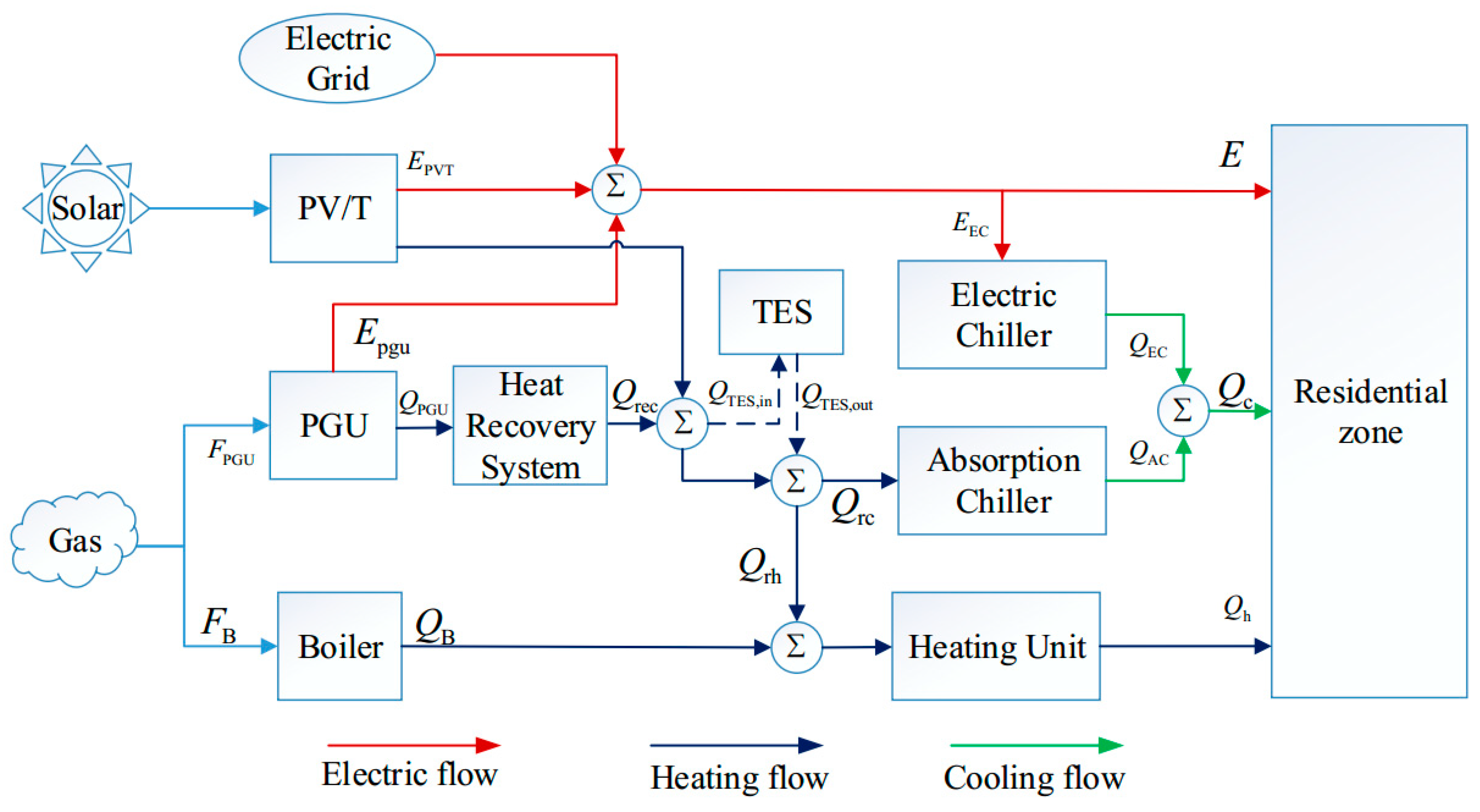
2.1. Description of CCHP System

The CCHP system structure and its energy flow are shown in Figure 1. In this paper, an internal combustion engine is set as the power generation unit. It consumes natural gas to produce electricity to meet the electricity demand in the residential zone, and the heat recovery system recovers the wasted heat from the PGU to supply thermal energy to the absorption chiller and heating exchanger. The cooling demand of the residential zone is met by an electric chiller or absorption chiller independently or jointly. PV/T panels are also added to the system to provide both electric and heat energy. A heat water tank is set as the thermal energy system. The external grid and the gas-fired boilers are the backup for electricity and heat, respectively.
As shown in Figure 1, the electric energy balance equation is:
E PGU + E PVT + E grid = E + E EC
where E PGU and E PVT are the electric power generated by the power generation unit and PV/T panels. The negative or positive of the variable E grid means electricity selling or purchasing from the upstream grid. E EC is the electric energy consumed by the electric chiller.
The thermal energy balance equations are:
Q PVT + Q HRS + Q TES = Q rc + Q rh + Q waste
Q EC + Q AC = Q c
Q B + Q rh = Q hreq
where Q PVT is the thermal energy generated by PV/T panels and Q HRS is the recovery heat from the heat recovery system. The negative or positive of the variable Q TES means that the thermal energy storage releases and absorbs heat. Q rc and Q rh are the recovery heat for cooling and heating, respectively. Q waste is the waste heat. The cooling load can be undertaken by electric chiller and absorption chiller. When Q rh is not sufficient to drive the heat exchanger to provide sufficient thermal energy, the gas-fired boiler works.
Assuming the heat needed to drive the absorption chiller to fulfill the total cooling load and the heat needed by the heating exchanger to fulfill the whole heating load are Q creq and Q hreq :
Q creq = Q c / η AC
Q hreq = Q h / η HE

2.2. Effective Operation Strategy

According to the CCHP system integrated PV/T panels and thermal energy storage, an effective operation strategy based on FEL is proposed. In this operation strategy, the low-grade heat from PV/T panels and thermal energy storage and medium-grade heat recovered from PGU can fulfill the heating and cooling loads. The output power generated by PGU should be coordinated with the PV/T panels, especially when the total amount of electricity generated by PV/T panels can meet the total power demand, and the PGU sets shutdown. The detail of this operation strategy are shown as:
Case 1: E PVT > E
In case 1, the PGU sets shut down. The low-grade heat energy collected by PV/T panels and discharged from the tanks preferentially meet the heating loads and the rest drive the water–LiBr absorption chiller. η AC 1 is the coefficient of the performance of the absorption chiller when it is running under a single-effect hot water driven state. Moreover, if E PVT > E + E EC , there is no need to purchase electricity from the upstream grid.
(a)
When the total solar thermal energy converted by PV/T panels and stored in heat tanks is not enough to fulfill the heating loads, the auxiliary gas-fired boiler and electric chiller start to make up the deficiency of thermal power.
Q PVT + min ( Q TES t Q TES , min , P TES , d , max ) Q hreq
F B = ( Q hreq Q PVT ) / η B
E EC = Q c / η EC
Q TES t + 1 = Q TES t
(b)
Q PVT could not even meet the heating demand. Added with the thermal energy in tanks, the sum of the thermal energy can only fulfill the heating demand. In this case, the sum of low-grade heat energy collected by PV/T panels and discharged from the tanks meets the heating loads first. The electric chiller and absorption chiller both start to provide the cooling loads.
{ Q PVT < Q hreq Q hreq < Q PVT + min ( Q TES t Q TES , min , P TES , d , max ) < Q hreq + Q creq
Q TES t + 1 = Q TES t min ( Q TES t Q TES , min , P TES , d , max )
E EC = Q c η AC 1 ( Q PVT + min ( Q TES t Q TES , min , P TES , d , max ) Q hreq ) η EC
(c)
Q PVT could not even meet the heating demand. Added with the thermal energy in tanks, the sum of the thermal energy can do both cooling and heating loads. The gas-fired boiler and electric chiller do not start.
{ Q PVT < Q hreq Q PVT + min ( Q TES t Q TES , min , P TES , d , max ) > Q hreq + Q creq
Q TES t + 1 = Q TES t + Q PVT Q hreq Q creq
(d)
Whether added to the thermal energy in tanks or not, Q PVT can only fulfill the heating loads. In this case, the electric chiller starts to make up the deficiency of cooling demand.
{ Q hreq + Q creq > Q PVT > Q hreq Q hreq + Q creq > Q PVT + min ( Q TES t Q TES , min , P TES , d , max ) > Q hreq
Q TES t + 1 = Q TES t min ( Q TES t Q TES , min , P TES , d , max )
E EC = Q c η AC 1 ( Q PVT + min ( Q TES t Q TES , min , P TES , d , max ) Q hreq ) η EC
(e)
Without adding the heat provided by the heat storage, the total heat source can only fulfill the heating load. However, added with the thermal energy in tanks, the total heat source can fulfill both the whole heating and cooling load.
{ Q hreq + Q creq > Q PVT > Q hreq Q PVT + min ( Q TES t Q TES , min , P TES , d , max ) > Q hreq + Q creq
Q TES t + 1 = Q TES t + Q PVT Q hreq Q creq
(f)
When Q PVT is enough to fulfill both heating and cooling loads, the surplus heat will be charged in thermal energy storage as much as possible.
Q PVT > Q hreq + Q creq
Q TES t + 1 = Q TES t + min ( Q PVT Q hreq Q creq , C TES Q TES t , P TES , ch , max )
Case 2: E PVT < E
In this case, when the part load factor of PGU is less than 0.25, the PGU should keep shut down and the energy flow of the CCHP is the same as in case 1. Additionally, the PGU runs according to the predicted renewable power E PVT . Especially when E PVT + E PGU , nom < E , the PGU runs in rated state. The expressions of E PGU and Q HRS are shown as
E PGU = { E E PVT E PVT + E PGU , nom > E E PGU , nom E PVT + E PGU , nomx < E
Q HRS = F PGU ( 1 η PGU ) η HRS
The medium-grade exhaust gas heat and low-grade heat, including jacket water and solar thermal energy, drive the double-effect water–LiBr absorption chiller. η AC 2 is the coefficient of performance of the absorption chiller when running under double-effect mode. The electric chiller would provide extra cooling energy if needed and the power consumption of the electric chiller is provided by the upstream grid.
(a)
When the total thermal energy provided by Q PVT , Q HRS and thermal energy storage cannot meet the heating demand, the auxiliary gas-fired boiler and electric chiller work. Meanwhile, the heat storage does not release heat.
Q PVT + Q HRS + min ( Q TES t Q TES , min , P TES , d , max ) Q hreq
Q TES t + 1 = Q TES t
F B = Q hreq Q HRS Q PVT η B
E EC = Q c / η EC
(b)
When the total thermal energy provided by Q PVT and Q HRS cannot meet the heating demand, but is added with the thermal energy in tanks, the sum of the thermal energy can only fulfill the heating loads. The lectric chiller starts to make up the deficiency of the cooling loads.
{ Q PVT + Q HRS < Q hreq Q hreq < Q PVT + Q HRS + min ( Q TES t Q TES , min , P TES , d , max ) < Q hreq + Q creq
Q TES t + 1 = Q TES t min ( Q TES t Q TES , min , P TES , d , max )
E EC = Q c η AC 2 ( Q PVT + min ( Q TES t Q TES , min , P TES , d , max ) Q hreq ) η EC
(c)
When the total thermal energy provided by Q PVT and Q HRS cannot meet the heating demand, but is added with the thermal energy in tanks, the sum of the thermal energy can fulfill the total thermal energy demand. In this case, the heat storage tanks release an appropriate amount of heat energy to meet the whole thermal loads, and meanwhile, the gas-fired boiler and electric chiller do not start.
{ Q PVT + Q HRS < Q hreq Q PVT + Q HRS + min ( Q TES t Q TES , min , P TES , d , max ) > Q hreq + Q creq
Q TES t + 1 = Q TES t + Q HRS + Q PVT Q hreq Q creq
(d)
Whether added with the thermal energy in tanks or not, Q PVT and Q HRS can only fulfill the heating loads. In this case, the heat storage tanks release energy as much as possible to meet the cooling demand. The electric chiller will make up for the above shortage of the cooling demand.
{ Q hreq + Q creq > Q PVT + Q HRS > Q hreq Q hreq + Q creq > Q PVT + Q HRS + min ( Q TES t Q TES , min , P TES , d , max ) > Q hreq
Q TES t + 1 = Q TES t min ( Q TES t Q TES , min , P TES , d , max )
E EC = Q c η AC 2 ( Q PVT + Q HRS + min ( Q TES t Q TES , min , P TES , d , max ) Q hreq ) η EC
(e)
When the total thermal energy provided by Q PVT and Q HRS can only meet the heating demand, but is added with the thermal energy in tanks, the sum of the thermal energy can fulfill the total thermal energy demand. In this case, the working states of heat storage tanks, electric chiller and gas-fired boiler are consistent with step c of Case 2.
{ Q hreq + Q creq > Q PVT + Q HRS > Q hreq Q PVT + Q HRS + min ( Q TES t Q TES , min , P TES , d , max ) > Q hreq + Q creq
Q TES t + 1 = Q TES t + Q HRS + Q PVT Q hreq Q creq
(f)
When the total thermal energy provided by Q PVT and Q HRS is enough to fulfill both heating and cooling loads, the surplus heat will be charged in thermal energy storage as much as possible.
Q PVT + Q HRS > Q hreq + Q creq
Q TES t + 1 = Q TES t + min ( Q PVT + Q HRS Q hreq Q creq , C TES Q TES t , P TES , ch , max )

2.3. Evaluation Criterion

2.3.1. Annual Total Cost

Annual total cost includes capital investment, natural gas and electricity purchasing cost and carbon tax, and the expressions of the above cost are as follows:
C ATC = C capital + C NG + C grid + C carbon
C capital = i ( 1 + i ) n ( 1 + i ) n 1 s = 1 r S s , nom × p s , unit
C NG = p NG t = 1 8760 F B t + F PGU t σ LHV
C grid = t = 1 8760 p grid t E grid t
C carbon = μ f p tax i = 1 8760 ( F B t + F PGU t )
where C ATC is the daily total energy cost; C capital , C NG , C grid and C carbon are the cost of capital investment, the cost of purchased natural gas, the cost of purchased electricity and carbon tax, respectively; in Equation (42), C s , nom and p unit , s are the installation capacity and unit cost of each component, respectively. i is the interest rate, and n is the system lifetime. In Equations (43)–(45), σ LHV is the natural gas converting factor of 1 m3 to kWh. p NG is the price of natural gas and p grid t is the time-of-use electricity price; p tax is the tax of carbon dioxide emission; μ f is the carbon dioxide emission of per-kilowatt-hour fuel.

2.3.2. Primary Energy Consumption and Primary Energy Saving Rate

The rate of primary energy saving is used to evaluate the energy-saving performance of the CCHP system compared with the current energy system performance of a residential zone. Thus, the rate of primary energy saving can be calculated as:
r PESR = ( 1 L PEC , CCHP L PEC , SP ) × 100 %
where L PEC , SP and L PEC , CCHP are the annual total primary energy consumption of separate system (SP) and CCHP system. The annual total primary energy consumption of those two systems is expressed as:
L PEC , SP = t = 1 8760 E t η trans η grid + t = 1 8760 Q c t η trans η grid η EC + t = 1 8760 Q h t η HE η b
L PEC , CCHP = t = 1 8760 ( F b t + F PGU t ) + t = 1 8760 E grid t η trans η grid

2.4. Assumptions in CCHP System

  • The proposed CCHP system is totally reliable and exporting electricity to external grid is not allowed.
  • The thermal storage system is an ideal model; there is no energy in the process of heat charging or discharging.
  • The models of electric chiller, absorption chiller and gas-fired boiler are based on a simplified hypothesis, and the efficiency of those components is considered to be a constant.
  • There is enough space on the roof or ground of the residential zone to install the required numbers of PV/T panels.

3. Optimization Method

3.1. Decision Variables

Decision variables include the capacity of the PGU S PGU , nom , the capacity of thermal energy storage S TES , nom , the capacity of the PV/T panels module S PVT , nom and the capacity of the absorption chiller. Once the rated capacity of these four devices is determined, the capacity of the remaining equipment in the CCHP system can be easily calculated or determined.

3.2. Objection Function

The optimization objective is to minimize the annual total cost of the CCHP system, and the mathematical model can be formulated as follows:
min C ATC = C capital + C NG + C grid + C carbon

3.3. Constraints Condition

Energy balance constraints are shown from the Equations (1)–(4). Each device in CCHP system has its own capacity. The constraints of PGU, the absorption chiller and gas-fired boiler are demonstrated in Equation (50). Note that the PGU works at least 0.25 of its maximum capacity if it is on.
{ 0.25 × S PGU , nom τ E PGU t S PGU , nom τ 0 Q AC t S AC , nom τ 0 Q B t S B , nom τ 0 Q EC t S EC , nom τ
where S PGU , nom , S AC , nom , S B , nom and S EC , nom are the nominal capacity of PGU, absorption chiller, gas-fired boiler and electric chiller. τ is the duration of each period.
The thermal energy storage constraints are shown in Equations (51)–(54).
α TES , d + α TES , ch 1
0 Q TES , d t α TES , d P TES , d , max
0 Q TES , ch t α TES , ch P TES , ch , max
Q TES , min Q TES t Q TES , nom
where α TES , d and α TES , ch are binary operation variables of thermal energy storage discharging or charging. The Equation (51) means the thermal energy storage is either charged or discharged for each period. In Equations (52) and (53), P TES , d , max and P TES , ch , max are the maximum discharging and charging power of the thermal energy storage, respectively. The thermal energy storage limitation is present in Equation (54).

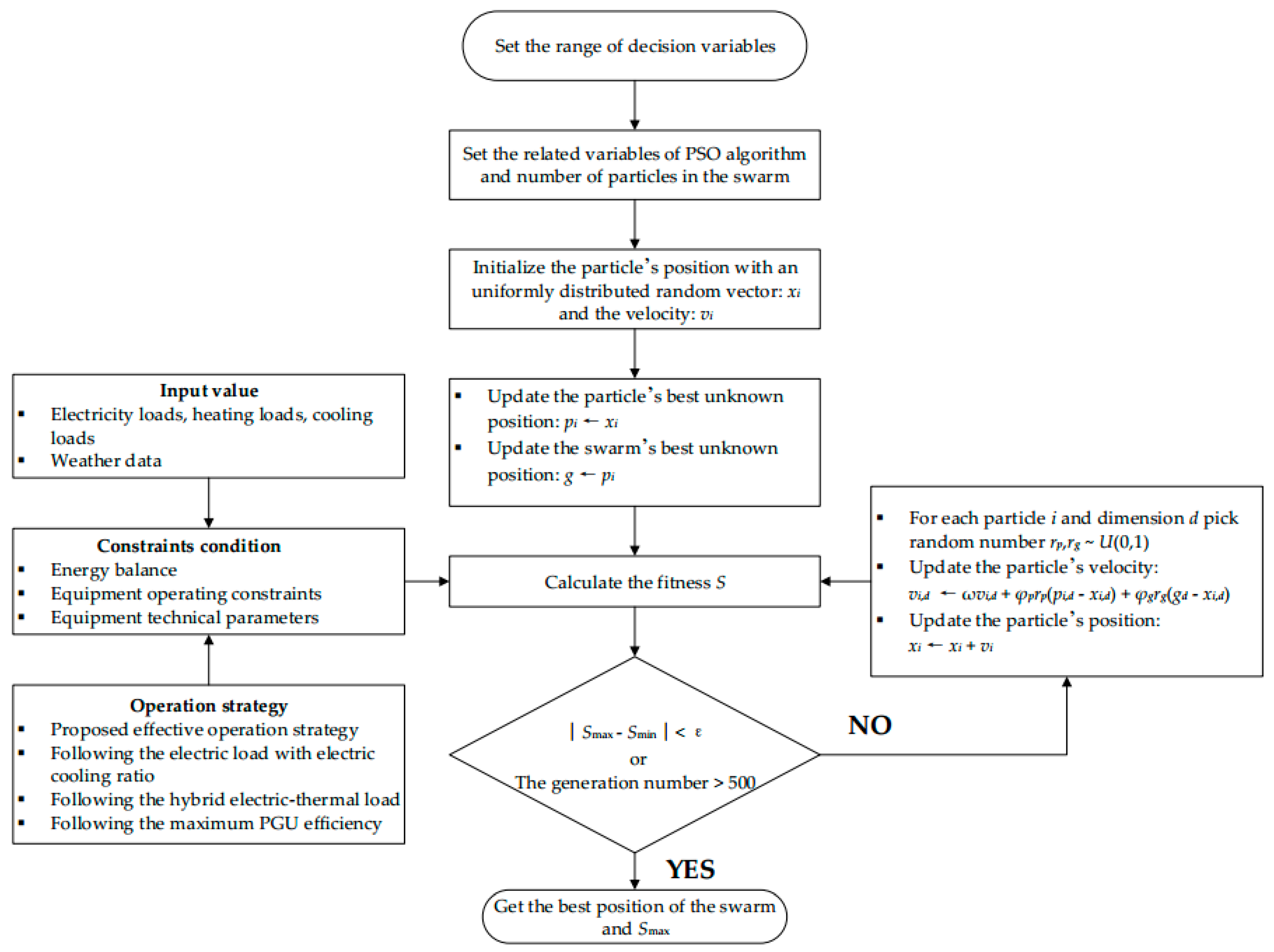
3.4. Solution Method

The PSO algorithm has the advantage of solving a nonlinear, multivariate, bound constraints problem effectively. Therefore, this algorithm is widely used in the planning and design of multi energy systems. As shown in Figure 2, the optimum installation capacity of the proposed CCHP system can be determined by using the particle swarm optimization algorithm. The decision variables and their range of variations are listed in Table 1. The PSO algorithm is implemented in the MATLAB software and applied to the simulation model of the proposed CCHP system.

4. Case Study

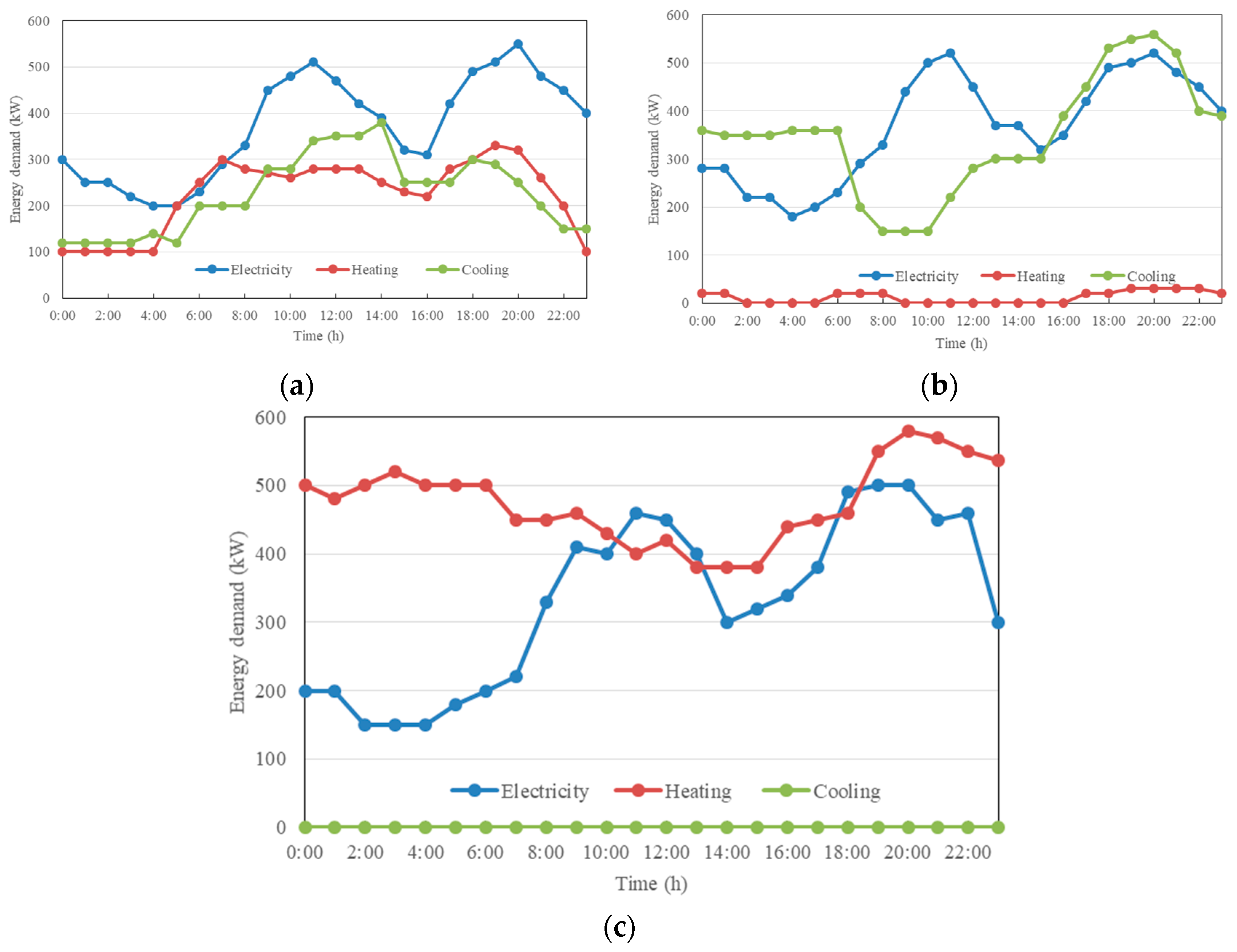
4.1. Case Introduction

To verify the effectiveness of the proposed method, a hypothetic residential zone in Beijing, China (40.08° N, 116.31° E) has had it implemented. The hourly cooling, heating and electric load profiles of a typical day in each season are shown in Figure 3a–c. It can be seen that there is no cooling load in winter because of the climate condition in Beijing, but there is a small amount of heating demand in summer due to the need for domestic heat water in this residential zone. The curve of solar radiation in different seasons is shown in Figure 4. In this study, the CCHP system is not allowed to sell electricity to the main grid.
The main parameters of the proposed CCHP system are listed in Table 2. A time-of-use electricity price mechanism is also implemented in this study and the economic parameters of the CCHP system are listed in Table 3. The specific technical parameters of the PV/T panels and PGU can be obtained in [12].
Four scenarios of the different configurations of CCHP system are listed in Table 4. Scenario 1 is the proposed CCHP system integrated with PV/T panels and TES systems, as shown in Figure 1. In scenarios 2 and 3, the CCHP system only integrate the PV/T panels and TES system, respectively. In scenario 4, the CCHP system is not equipped with either PV/T panels or TES systems.

4.2. Analysis and Discussion

4.2.1. Optimal Design Parameters of the CCHP System under Different Operation Strategies

In order to find the optimum capacity of the key equipment in the CCHP system as described in scenario 1, simulation and optimization of the CCHP system are carried out under four operation strategies, i.e., following electric load with electric cooling ratio (FEL-ECR), FTL, FHL and following the maximum PGU efficiency (FME). The characteristics of these four modes can be obtained in [12,13]. The optimized design parameters are listed in Table 5.
It is easy to see that the annual total cost of the CCHP system reaches its lowest by adopting the proposed effective operation strategy. In this mode, the largest capacity of PV/T panels and the smallest capacity of PGU are selected.

4.2.2. Analysis of Economic and Environmental Results of Different Operation Strategies

In order to verify the effectiveness of the proposed method, the following four common operation strategies, i.e., FEL-ECR, FTL, FHL and FME, are also applied in scenario 1 for comparison. The capacity of the key equipment of the CCHP system has been determined by the optimization process in Section 4.2.1. The simulation results are shown in Figure 5.
It is observed that the maximum value of the primary energy saving ratio can be achieved when the proposed effective operation strategy is used. Under FTL and FME modes, the values of the primary energy saving ratio are all lower than 20%. Under the FME mode, the overall performance is no good because the extra power generated by PGU cannot be sold to the main grid. Similarly, applying the FTL mode also suffers from this situation.
As for the economic performance, both the proposed method and FEL-ECR achieve better performances than the remaining three models. The proposed strategy in this paper achieves a better performance in fuel cost, which results in a slightly better performance in cost-saving than the FEL-ECR does.
In conclusion, in a CCHP system with the integration of PV/T panels and thermal energy storage, applying the proposed effective operation strategy can achieve the most outstanding performance in annual cost saving and primary energy saving simultaneously.

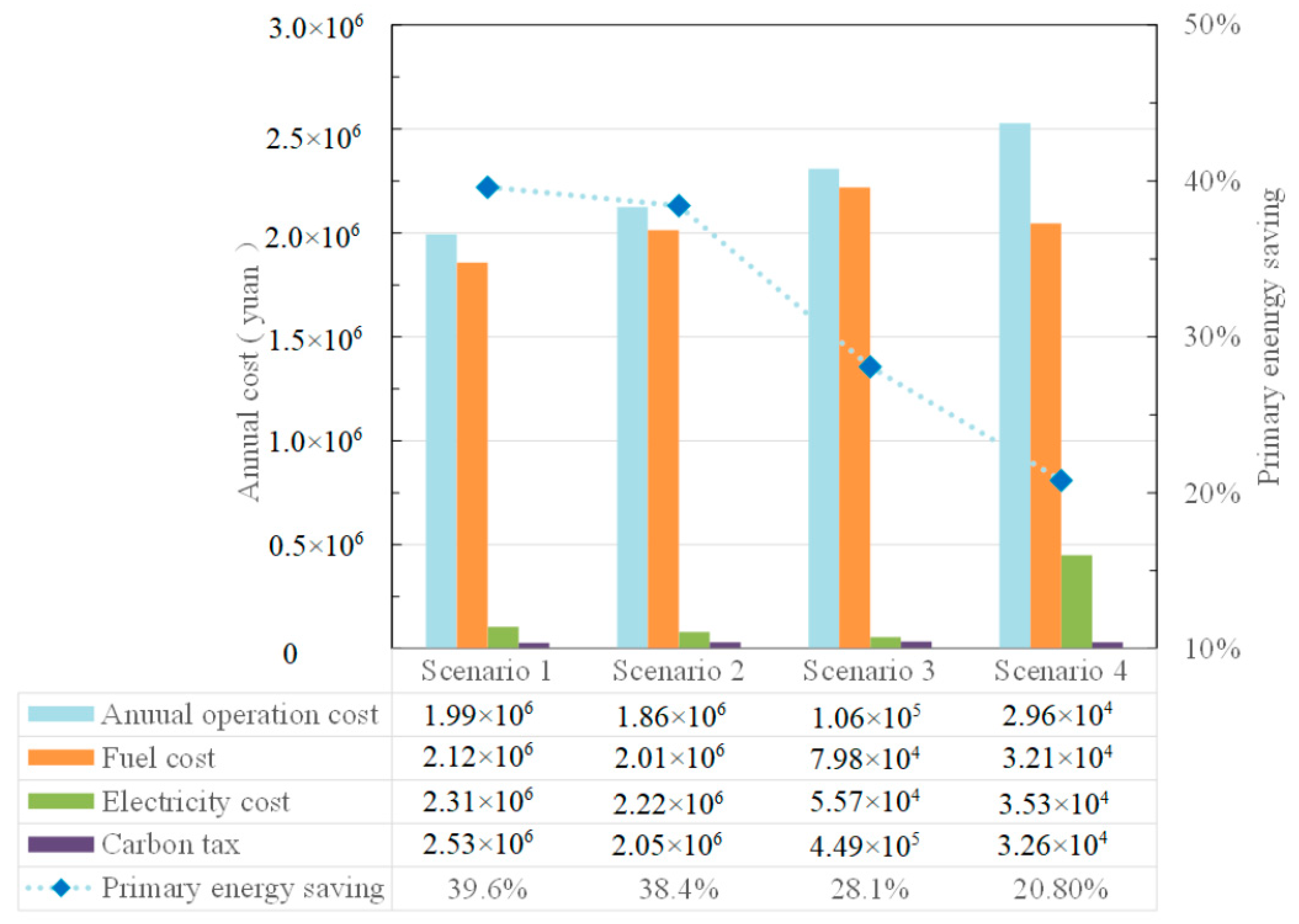
4.2.3. Analysis of Economic and Environmental Results in Different Scenarios

Applying the effective operation strategy described above, the simulation results for economy and environment are shown in Figure 6 and Figure 7. In this section, we define the total operation cost as the sum of fuel cost, electricity purchase cost and carbon tax cost. It can be found that in terms of economy and primary energy saving, this configuration in scenario 1 performs best.
Excluding the thermal energy storage, as shown in scenario 2, the total operation cost is 3.012 × 10⁴ yuan more than the cost in scenario 1. The increase in the annual operation cost is mainly due to the purchase of electricity. In terms of primary energy saving rate, the index is still high, and it is decreased by 1.4% after the removal of heat water tanks. However, without the energy storage, the value of annual wasted heat is the second highest in four scenarios, only 1.73 × 10⁴ kWh less than the maximum.
Excluding the PV/T panels, as shown in scenario 3, although the electricity purchase cost decreases, the annual operation cost of this CCHP system still goes up further, reaching 2.346 × 10⁶ yuan. That is because more natural gas is needed for PGU to generate enough electricity. Meanwhile, more electricity generated by PGU may cause more recovered exhaust heat to drive the absorption chiller to meet the cooling demand. It can be observed for Figure 6 that the annual total recovered heat reaches 2.86 × 10⁶ kWh. Of the total recovered heat, 1.71 × 10⁶ kWh is used for driving the absorption chiller and this value is also the largest of the four scenarios. That is the reason why the cost of electricity purchasing in scenario 3 is the lowest, reaching 7.635 × 10⁶ yuan. Moreover, in terms of primary energy saving, the saving ratio falls further, to 28.1%.
Without electric and thermal energy converted by PV/T panels and extra heat stored in thermal energy storage, in scenario 4, obviously the annual economic and environmental performance are worst. The value of the electricity purchased cost is the highest and the ratio of primary energy saving is the lowest among the four scenarios. Additionally, the value of annual wasted heat is the highest, reaching 1.12 × 10⁶ kWh.
Overall, with the integration of the PV/T panels and thermal energy storage, a significant improvement in economy and environment can be obtained. Consequently, further simulation for operation strategy comparison and energy flow analysis will continue to use the CCHP structure as scenario 1 describes.

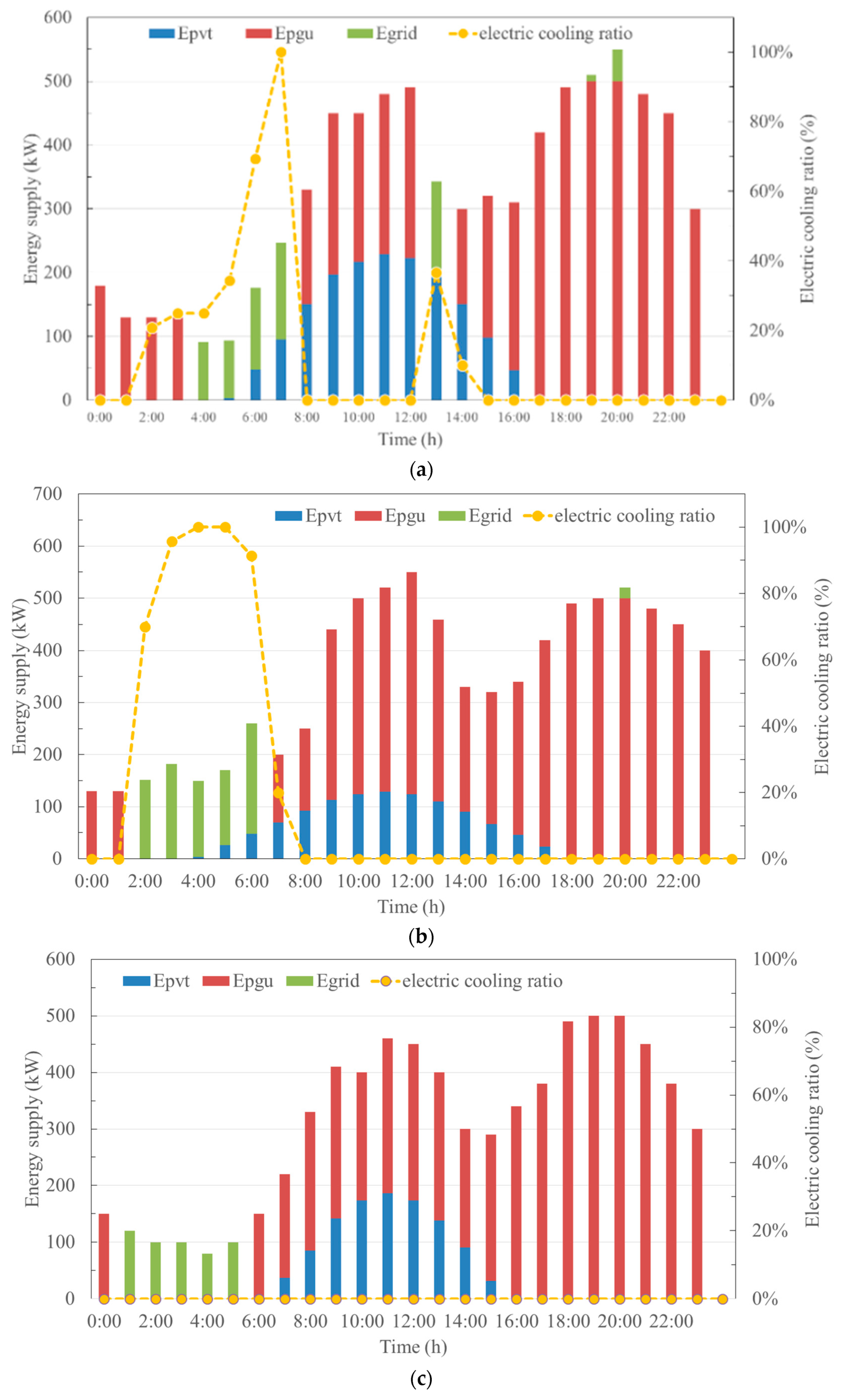
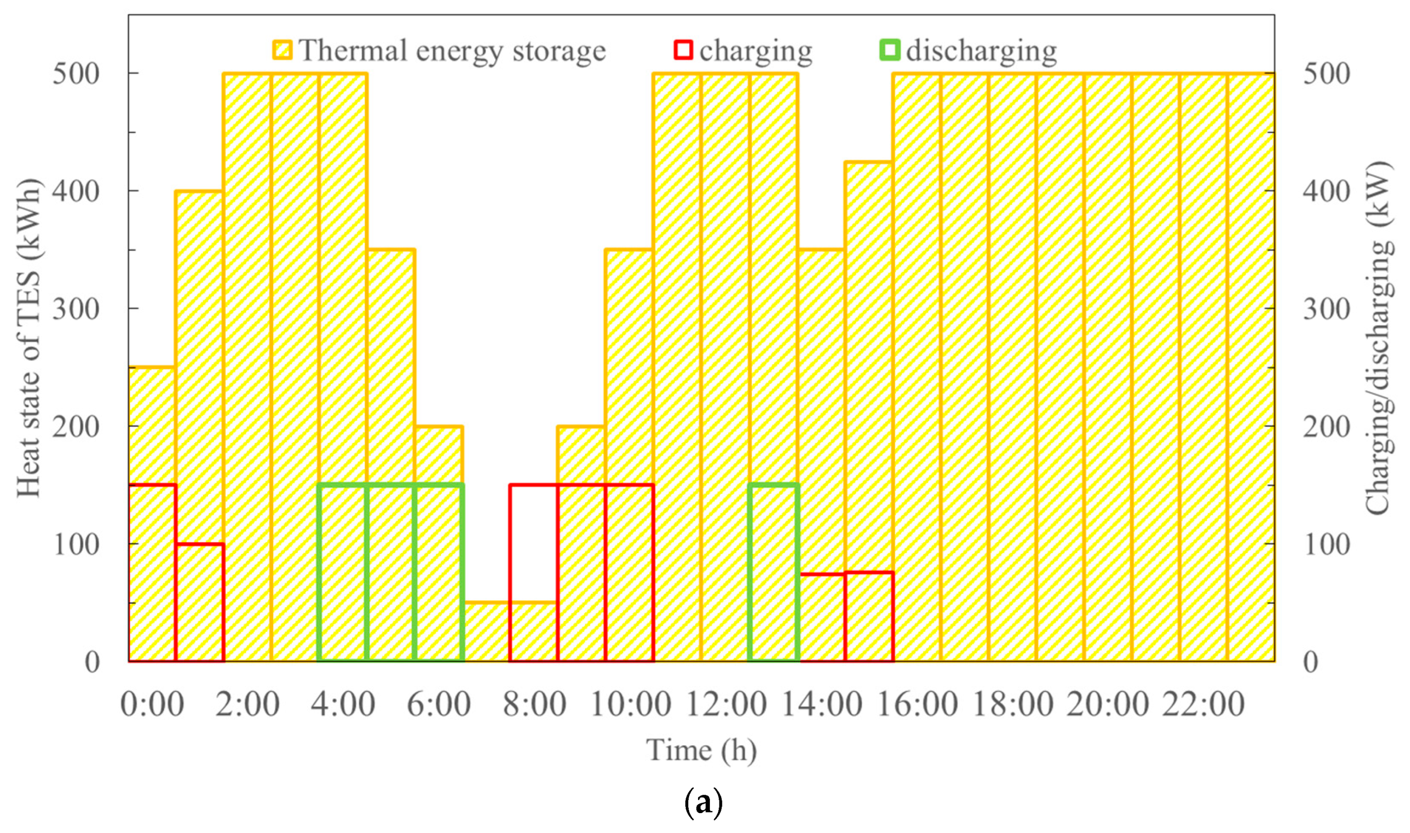
4.2.4. Analysis of Energy Flow in a Typical Day

Applying the optimal operation strategy described above in the CCHP system of scenario 1, the hourly energy supply of each component and the electric cooling ratio of the residential zone are shown in Figure 8a–c.
It can be seen that PGU is usually shut down in the early hours of the morning due to the low part load factor. During this period, the power demand is provided by the main grid. Additionally, during this period of summer and a transition season, the electric cooling ratio rises rapidly, which is due to the shutdown of PGU, resulting in no recoverable heating for driving the absorption chillers. The increase of electric cooling ratio also indicates that the cooling energy demand needed to be satisfied by the electric chillers driven by the electric power purchased from the upstream grid.
In the daytime, a considerable share of power demand is provided by PV/T panels and PGU. During this period, the electric cooling ratio remains zero. The total cooling demand is satisfied by the absorption chillers driven by the heat generated by PV/T panels and recovered from PGU. It is notable that PGU goes into shutdown in midday in the summer due to the lower part load factor of the PGU. During this period, the electric power demand is satisfied by PV/T panels and thermal demand is also covered by PV/T panels and thermal energy storage.
At night, most of the power demand is satisfied by the PGU and the rest is provided by the main grid. The PGU is always running at the rate stated and a large amount of exhausted heat is recovered to drive the absorption chillers or heating units. Especially in winter, there is no cooling demand in the residential zone, which also causes the electric cooling ratio to be a constant of zero in a whole day.
Applying the proposed operation strategy, assuming initial heat storage is half of the maximum heat storage capacity, the changing reserve thermal energy per hour in TES of the CCHP system in the structure of scenario 1 is shown in Figure 9. It can be observed that in transition season and summer, much more surplus thermal energy exists during the operation process, and part of it can be charged into the TES to avoid the waste of energy, especially in the morning of those seasons. Once the TES is full of heat, reaching its maximum storage limit, no more recovered heat can be charged, especially in the night of the transition season. When the recovered heat from the PGU cannot meet the thermal loads, the thermal energy stored in TES should be released immediately to fulfill the thermal demand of the residential zone, especially in the night of summer. It is noted that less heat will be charged into TES in winter. That is because of there is a great demand for heat in winter and the recovered heat is almost used to meet the heat loads.

5. Conclusions

In this paper, a CCHP system integrated with PV/T panels and thermal energy storage is presented. An effective operation strategy is put forward and this strategy is applied to a residential zone in four CCHP structure scenarios. By comparison with any other basic operation modes, the proposed method can achieve better performance in cost saving and primary energy saving. Through the simulation results and discussions, the following valuable conclusions can be summarized:
  • Adding the PV/T panels into the conventional CCHP, as scenario 2 has shown, the original value of primary energy saving is increased by 17.6%. The electricity purchased cost is greatly reduced by 3.264 × 10⁵ yuan. The self-sufficiency rate of electric energy has been improved greatly. Adding the thermal energy storage into the conventional CCHP, as scenario 3 has shown, the original value of primary energy saving is increased by 7.3%.
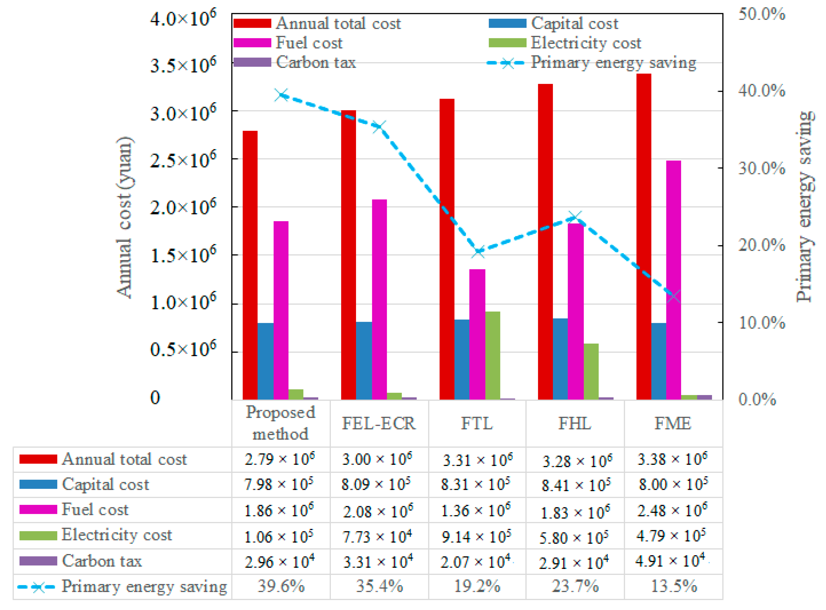
  • The application of CCHP with the integration of PV/T panels and thermal energy storage in a residential zone can achieve better effects for cost saving and energy saving. Compared with the conventional CCHP system, the value of primary saving increases greatly by 39.6% and the total cost decreases dramatically.
  • The CCHP system under FTL and FME modes achieve much worse performance in primary energy saving. Compared with those two modes, applying the FHL may achieve better performance in primary energy saving, but does not perform well in cost saving. Compared with any other basic operation modes, the proposed operation strategy is much more suitable for the CCHP system with the integration of PV/T panels and thermal energy storage.

Author Contributions

All the authors made contributions to the concept and design of the article. Conceptualization, Y.M. and J.W.; Methodology, Y.M.; Software, W.Z. and Z.C.; Validation, Y.M. and W.Z.; Formal Analysis, Y.M.; Investigation, J.W.; Resources, J.W.; Data Curation, Y.M.; Writing—Original Draft Preparation, Y.M.; Writing—Review & Editing, Y.M.; Visualization, W.Z. and R.W.; Supervision, J.W. All authors have read and agreed to the published version of the manuscript.

Funding

This research was supported in part by the Guangdong Applied Science and Technology Research Foundation, China, under Grant 2016B020244003.

Conflicts of Interest

The authors declare no conflict of interest.

References

  1. Cho, H.; Smith, A.D.; Mago, P. Combined cooling, heating and power: A review of performance improvement and optimization. Appl. Energy 2014, 136, 168–185. [Google Scholar] [CrossRef]
  2. Gu, W.; Wu, Z.; Bo, R.; Liu, W.; Zhou, G.; Chen, W. Modeling, planning and optimal energy management of combined cooling, heating and power microgrid: A review. Int. J. Electr. Power Energy Syst. 2014, 54, 26–37. [Google Scholar] [CrossRef]
  3. Liu, M.; Shi, Y.; Fang, F. Combined cooling, heating and power systems: A survey. Renew. Sustain. Energy Rev. 2014, 35, 1–22. [Google Scholar] [CrossRef]
  4. Maryam, F.; Amirhassan, S. Solar assisted CCHP system, energetic, economic and environmental analysis, case study: Educational office buildings. Energy Build. 2017, 136, 100–109. [Google Scholar] [CrossRef]
  5. Wang, Y.; Wu, J.; Mao, X. Intelligent scheduling optimization of seasonal CCHP system using rolling horizon hybrid optimization algorithm and matrix model framework. IEEE Access 2018, 6, 75132–75142. [Google Scholar] [CrossRef]
  6. Wegener, M.; Malmquist, A.; Isalgué, A.; Martin, A. Biomass-fired combined cooling, heating and power for small scale applications—A review. Renew. Sustain. Energy Rev. 2018, 96, 392–410. [Google Scholar] [CrossRef] [Green Version]
  7. Li, B.; Hu, P.; Zhu, N.; Lei, F.; Xing, L. Performance analysis and optimization of a CCHP-GSHP coupling system based on quantum genetic algorithm. Sustain. Cities Soc. 2019, 46, 101408. [Google Scholar] [CrossRef]
  8. Rostamzadeh, H.; Ebadollahi, M.; Ghaebi, H.; Shokri, A. Comparative study of two novel micro-CCHP systems based on organic Rankine cycle and Kalina cycle. Energy Convers. Manag. 2019, 183, 210–229. [Google Scholar] [CrossRef]
  9. Mahmood, C.; Mohammad, S. Energy, environmental and economic evaluations of a CCHP system driven by Stirling engine with helium and hydrogen as working gases. Energy 2019, 174, 1251–1266. [Google Scholar] [CrossRef]
  10. Houssein, A.M.; Farouk, F.; Hasna, L. Selection based on differences between cogeneration and trigeneration in various prime mover technologies. Renew. Sustain. Energy Rev. 2017, 74, 491–511. [Google Scholar] [CrossRef]
  11. Su, B.; Han, W.; Qu, W.; Liu, C.; Jin, H. A new hybrid photovoltaic/thermal and liquid desiccant system for trigeneration application. Appl. Energy 2018, 226, 808–818. [Google Scholar] [CrossRef]
  12. Yousefi, H.; Ghodusinejad, M.; Kasaeian, A. Multi-objective optimal component sizing of a hybrid ICE + PV/T driven CCHP microgrid. Appl. Therm. Eng. 2017, 122, 126–138. [Google Scholar] [CrossRef]
  13. Yang, G.; Zhai, X. Optimization and performance analysis of solar hybrid CCHP systems under different operation strategies. Appl. Therm. Eng. 2018, 133, 327–340. [Google Scholar] [CrossRef]
  14. Yang, G.; Zhai, X. Optimal design and performance analysis of solar hybrid CCHP system considering influence of building type and climate condition. Energy 2019, 174, 647–663. [Google Scholar] [CrossRef]
  15. Herrando, M.; Pantaleo, A.; Wang, K.; Markides, C. Solar combined cooling, heating and power systems based on hybrid PVT, PV or solar-thermal collectors for building applications. Renew. Energy 2019, 143, 637–647. [Google Scholar] [CrossRef]
  16. Mohammadkhani, N.; Sedighizadeh, M.; Esmaili, M. Energy and emission management of CCHPs with electric and thermal energy storage and electric vehicle. Therm. Sci. Eng. Progress 2018, 8, 494–508. [Google Scholar] [CrossRef]
  17. Liu, W.; Chen, G.; Yan, B.; Zhou, Z.; Du, H.; Zuo, J. Hourly operation strategy of a CCHP system with GSHP and thermal energy storage (TES) under variable loads: A case study. Energy Build. 2015, 93, 143–153. [Google Scholar] [CrossRef]
  18. Zheng, C.; Wu, J.; Zhai, X.; Wang, R. A novel thermal storage strategy for CCHP system based on energy demands and state of storage tank. Electr. Power Energy Syst. 2017, 85, 117–129. [Google Scholar] [CrossRef] [Green Version]
  19. Li, L.; Yu, S.; Mu, H.; Li, H. Optimization and evaluation of CCHP systems considering incentive policies under different operation strategies. Energy 2018, 162, 825–840. [Google Scholar] [CrossRef]
  20. Liu, T.; Zhang, D.; Wang, S.; Wu, T. Standardized modelling and economic optimization of multi-carrier energy systems considering energy storage and demand response. Energy Convers. Manag. 2019, 182, 126–142. [Google Scholar] [CrossRef]
  21. Wang, J.; Sui, J.; Jin, H. An improved operation strategy of combined cooling heating and power system following electrical load. Energy 2015, 85, 654–666. [Google Scholar] [CrossRef]
  22. Zhang, T.; Wang, M.; Wang, P.; Liang, J. Optimal Design of a Combined Cooling, Heating, and Power System and Its Ability to Adapt to Uncertainty. Energies 2020, 13, 3588. [Google Scholar] [CrossRef]
  23. Lingmin, C.; Jiekang, W.; Fan, W.; Huiling, T.; Changjie, L.; Yan, X. Energy flow optimization method for multi-energy system oriented to combined cooling, heating and power. Energy 2020, 211, 118536. [Google Scholar] [CrossRef]
  24. Yang, H.; Xiong, T.; Qiu, J.; Qiu, D.; Dong, Z.Y. Optimal operation of DES/CCHP based regional multi-energy prosumer with demand response. Appl. Energy 2016, 167, 353–365. [Google Scholar] [CrossRef]
  25. Wang, Q.; Liu, J.; Hu, Y.; Zhang, X. Optimal operation strategy of multi-energy complementary distributed CCHP system and its application on commercial building. IEEE Access 2019, 7, 127839–127849. [Google Scholar] [CrossRef]
Figure 1. Scheme of combined cooling, heating and power (CCHP) system and its energy flow.
Energies 13 06418 g001
Figure 2. The flow chart of the optimization method based on the particle swarm optimization.
Energies 13 06418 g002
Figure 3. Load profiles of a residential zone in different season: (a) transition season; (b) summer; (c) winter.
Energies 13 06418 g003
Figure 4. Solar radiation in different seasons.
Energies 13 06418 g004
Figure 5. Annual cost and primary energy saving under different operation strategies.
Energies 13 06418 g005
Figure 6. Economic and environmental results in different scenarios.
Energies 13 06418 g006
Figure 7. The annual recovered heat and waste heat in different scenarios.
Energies 13 06418 g007
Figure 8. Energy load supply of a residential zone in different season: (a) transition season; (b) summer; (c) winter.
Energies 13 06418 g008
Figure 9. The hourly energy flow of thermal energy storage in different season: (a) transition season; (b) summer; (c) winter.
Energies 13 06418 g009aEnergies 13 06418 g009b
Table 1. The range of variations of the decision variables.
VariablesSymbolUnitRange
Capacity of the power generation unit (PGU) S PGU , nom kW[0, 10 × max(E)]
Capacity of the hybrid photovoltaic/thermal (PV/T) panels S PVT , nom kW[0, 10 × max(E)]
Capacity of the thermal energy storage (TES) S TES , nom kW[0, 30 × max(Qh)]
Capacity of the AC S AC , nom kW[0, 10 × max(Qc)]
Table 2. Main parameters of the combined cooling, heating and power (CCHP) system.
ParameterUnitValueParameterUnitValueParameterUnitValue
Q TES , min kW50 η EC -4 τ h1
P TES , ch , max kW150 η HE %80n-20
P TES , d , max kW150 η B %90i-0.08
η HRS %80 η grid %32
η AC 1 -0.7 σ LHV kWh / m 3 9.78
η AC 2 -0.9 μ f kg / kWh 0.202
Table 3. Economic parameters of the CCHP system.
ParameterRepresentativeValue
Unit price p s , unit PGU8000 yuan/kW
PV/T panels12,500 yuan/kW
Thermal energy storage230 yuan/kW
Absorption chiller1500 yuan/kW
Electric chiller1000 yuan/kW
Heating exchanger150 yuan/kW
Boiler180 yuan/kW
Utility electricity price p grid t Peak: 14:00–16:59,19:00–21:590.87 yuan/kWh
Flat: 8:00–13:59, 17:00–18:59, 22:00–23:590.61 yuan/kWh
Valley: 0:00–7:590.31 yuan/kWh
Price of natural gas p NG Whole day2.70 yuan/m3
Carbon tax p tax Whole day0.02 yuan/kg
Table 4. Different scenarios of different configuration in CCHP system.
ScenariosEquipment in a CCHP System
PGUHRSPV/TTESHEBoilerACEC
scenario 1
scenario 2×
scenario 3×
scenario 4××
Table 5. Optimum configuration of the CCHP system under different operation strategies.
Operation StrategyPGU/kWTES/kWPV/T/kWEC/kWAC/kWBoiler/kWCATC/yuan
Following electric load with electric cooling ratio (FEL-ECR)5305502602803806508.41 × 105
Following thermal load (FTL)5103301805101206508.68 × 105
Following hybrid load (FHL)5255422203502106508.72 × 105
Following the maximum PGU efficiency (FME)5506501704601506508.33 × 105
Proposed method5006303503605606508.27 × 105
Publisher’s Note: MDPI stays neutral with regard to jurisdictional claims in published maps and institutional affiliations.

