Article

Experimental Characterization and Evaluation of the Vibroacoustic Field of Hydraulic Pumps: The Case of an External Gear Pump

Maha Fluid Power Research Center, Purdue University, 1500 Kepner dr., Lafayette, IN 47905, USA
*
Author to whom correspondence should be addressed.
Energies 2020, 13(24), 6639; https://doi.org/10.3390/en13246639
Submission received: 5 November 2020 / Revised: 12 December 2020 / Accepted: 14 December 2020 / Published: 16 December 2020
(This article belongs to the Special Issue Gear Pumps and Motors)

Abstract

:
This paper presents the experimental characterization of the vibroacoustic fields and the evaluation of noise performances of hydraulic pumps. Research on hydraulic pump noise has traditionally focused on the fluid-borne noise sources, and very often the analyses of vibration and noise have been performed focusing on a few local points. This trend results in the lack of investigation on the overall behaviors of vibroacoustic fields of hydraulic pumps, and it has been one of the obstacles to understand the complete mechanisms of noise generation. Moreover, despite the existence of the ISO standards for the determination of noise levels, diverse metrics have been used for the evaluation of noise performances of the pumps, but the adequacy of these metrics has not been carefully examined. In this respect, this paper aims at introducing a way to characterize and interpret the measured vibroacoustic field and providing proper methods which are also capable of applying the ISO standards for the fair assessment of pump noise performances. For the characterization of the vibroacoustic field, operational deflection shapes (ODS) and corresponding radiated sound fields are visualized at harmonics of the pumping frequency by using a spectral analysis. Observations are made regarding the motions of the pump and its mounting plate and the resultant radiated noise, depending on the frequency, as well as their correlation. A numerical analysis using the Rayleigh integral equation is also performed to further investigate the contribution of the mounting plate motion on the noise radiation. For the evaluation of noise performance, two different units are tested at multiple operating conditions, and comparisons are made based on their measured sound power levels (SWLs) and sound pressure levels (SPLs). The results emphasize the importance of SWL measurement for the fair noise performance evaluation, and the two methods are proposed as practices to determine the minimum number of measurement points for practicability and to have reliable sound power determination for hydraulic pumps.

1. Introduction

Excessive acoustic noise and vibrations are important detrimental aspects for fluid power systems, and positive displacement machines (i.e., hydraulic pumps and motors) are known to be the dominant source of noise and vibration. Recently, the noise issue is drawing more attention within the fluid power technical community owing to the current trend of the machine electrification involving both off-road and on-road mobile fields [1,2,3]. In fact, quiet electric machines are replacing internal combustion engines as prime movers of hydraulic drive systems and thus the noise emissions from the hydraulic units become more evident. As a consequence, the level of emitted noise and vibration has become an important metric to evaluate the unit performance along with hydraulic efficiencies parameters (i.e., volumetric and mechanical efficiency). This is confirmed by the fact that the noise level is often reported in the specification sheets of hydraulic pumps.
To mitigate the excessive noise and vibration of the fluid power systems, fundamental research and modeling works have been carried out on noise generation and its propagation. Most of the successful solutions are based on the minimization of the flow/pressure ripple at the delivery port, which is often considered as the main source of fluid-borne noise (FBN). For example, for the case of axial piston pumps, significant effort has been made to model and measure the source/line impedances [4,5,6,7,8] and optimize the valve plate designs to reduce the flow ripple [9,10,11,12]. As pertains to external gear pumps, similar analyses have been made by proposing different porting grooves [13], alternative gear profiles spamming from standard involute [14,15] to non-involute [15,16,17,18], and considering the effect of fluid compressibility [19,20]. From these analyses, the minimization of the pressure ripples at the delivery port has been proved to be effective on the noise reduction in the system level. This is because the pressure ripples propagate into the system connected to the pump. However, the effectiveness of the pressure ripple reduction on mitigating the overall noise radiated through a pump case is still questionable. This was widely discussed by Edge [21], who showed a case where no change in the noise level is observed even with a large reduction in the amplitudes of the pressure ripple. Therefore, the understanding of the underlining causes of the noise radiated from the pump casing, as well as objective methods to quantify the noise emission, is still a topic of relevance for the fluid power technical community.
In this area of research, there exists a growing body of literature on modeling the noise emissions from the casing of the positive displacement machines. Significant works are given by the references [9,22,23,24,25,26,27,28,29,30], and they have contributed to the advancement of the modeling capability for the various aspects of dynamic behaviors occurring in the units. However, these works are generally based on modeling approaches with high computational cost, which attempt considering all the complicated interactions in fluid, structure, and air domain. Such approach does not allow performing extensive studies on the effect of various design parameters as well as different operating conditions. As a consequence, the complete mechanisms of noise generation and radiation from a pump case still have not been clearly understood. Another limitation of most of these works is that the effect of the pump mounting conditions is usually not considered. The lack of consideration about the mounting elements (usually mounting plates) can be motivated to the purpose of maintaining a more generic approach. This is because the mounting condition varies depending on the application. Moreover, it has not been clearly proved that the mounting has significant impacts on noise and vibration of hydraulic pumps. However, the mounting elements can affect the structural dynamic behaviors of the pump as important boundary conditions, and there is a high chance that they can serve as an additional noise radiator as the structure-borne noise of the pump propagates to these elements. In this regard, an assessment on the contribution of the mounting elements have on the noise radiation is an important matter to further advance research on pump noise modeling as well as for more rigorous model validation.
The noise reductions discussed in several reports are obtained by using some treatments such as the inclusion of additional damping elements [31,32], the change of stiffness by means of some modifications of the casing structures [27,33,34], the replacement of the gears with different materials [35], and the active control of the swash plate vibration [36,37]. Although these methods proved to be effective in achieving noise reductions, their strategies focus on the certain aspects of the noise generation or reduction of vibrations at few local points, such as the change of modal parameters or the transfer path of the structural vibration [27,31,32,33,34] and the reduction of the particular noise source such as the gear contact forces [35], or the swash plate moment in axial piston units [36,37]. The seeming lack of the noise solutions based on the complete noise generation mechanism in the existing literature also points out that the vibroacoustic field of hydraulic pumps necessitates of further investigation. Therefore, an important goal of this paper is to fill this technological gap by providing an experimental method for characterizing and interpreting the vibroacoustic field generated from the pump casing as well as the mounting plate, so that research towards silent pump technology can benefit from this study.
Furthermore, researchers in the fluid power community have been using different metrics to evaluate the noise emissions. The evaluation of the noise performance of a certain solution, sometimes even with the purpose of validating the results of a numerical model, often relies on simple measurements of the sound pressure and acceleration at one or few measurement points [21,23,26,29,31,34,35,36,37]. Actually, the ISO standards provide guidance as pertains to the evaluation of the noise performance, but it seems to be used in very limited cases, most likely due to technical implementation difficulty and cost reasons. Accordingly, relatively few studies exist that consider the sound power determined by the measurements at multiple points, as suggested by the ISO standards [9,22,25]. With the ISO standards, the noise levels can be determined with high fidelity. On the other hand, simple measurements taken at few points are more practical and inexpensive, but the questions still remain unanswered as to what is the possible error of this practice and how many measurement points are required to determine the noise level within the acceptable range of errors for practicability reason. Unless a proper justification is provided regarding these questions, the results given by a simplified noise measurement can be misleading because the noise and vibration of hydraulic pumps usually exhibit high spatial variations. Therefore, a proper and accurate measurement method, which is also capable of evaluating the noise level according the ISO standards, needs to be examined to have a balance between practicability and reliability for the fair assessment of noise performances of hydraulic pumps. In this respect, this paper presents the experimental investigations characterizing the overall vibroacoustic behaviors of the pump under actual operation at harmonics of the pumping frequency and reviewing the proper evaluation of overall noise performance of hydraulic pumps. To attain both goals, in theory, the vibroacoustic measurements should be simultaneously taken at a large number of positions throughout the field. Taking as reference the case of external gear pumps, tests are performed during the steady-state operation of the pump (meaning constant shaft speed and port pressures) by moving the minimal number of sensors in a semi-anechoic chamber at Maha Fluid Power Research Center. The analysis is accomplished under the assumption that the noise and vibration do not change during the steady-state operation, and the results prove that this assumption is valid.
The layout of this paper is as follows: The following Section 2 describes how the hydraulic tests of this work are set up for the noise and vibration measurements. Then, Section 3 summarizes the effort made to characterize the vibroacoustic field, by properly visualizing and discussing its dynamic behavior at each frequency. The spectral analyses are used to extract their magnitude and relative phase at different locations through a signal synchronization. The results of the visualized vibrational motions, which are often called ODS, as well as the radiated sound field providing some interesting observations including how vibrational motions change depending on the frequency and correlation between ODS and radiated noise. The numerical analysis using the Rayleigh integral equation is also performed to further investigate one of the observations as pertains to the contribution of the mounting plate on noise radiation. After that, the potentials and limitations of this analysis are discussed in the last part of the Section 3. Concerning overall noise performance evaluation, SPL and SWL are compared in the Section 4. As the results highlight the importance of the sound power measurement, Section 4 also discusses two practices (grid study and repeatability test) to help decide the number of measurement points and ensure a reliable sound power determination.

2. Hydraulic Test Setup

A hydraulic open circuit configuration is used to test the noise and vibration of hydraulic pumps, as shown in Figure 1. To isolate and measure only the noise radiated from the pump, the pump and parts of connecting lines including the inlet temperature and pressure sensors are inside a sound chamber (highlighted with the blue dashed box in the figure), while the other components are outside of the sound chamber. A needle valve (variable orifice) is used to load the pump at the desired operating pressure, and a pressure relief valve is installed in parallel with the needle valve for safety. The oil conditioning system (i.e., thermal and filtration system) is placed after the loading valve, and it allows controlling the oil temperature and avoiding oil contamination issues. The detailed information about each component is tabulated in Table 1.

3. Characterization of Vibroacoustic Field during Operation

The vibration of hydraulic pumps induces movements of air particles adjacent to the structures and the noise to propagate to the surrounding air. For this reason, the understanding of vibrational motions at the surface of the structure is a crucial step to properly understand the mechanism of the radiated noise. Hence, the ODS and corresponding radiated noise field are measured simultaneously, and how they are correlated will be discussed in this section.
Both ODS and radiated noise field can be described as the spatial variations of complex valued physical quantities at the frequency of interest (periodic temporal variations are dropped out by courtesy of the Fourier transform, and the physical quantities become complex-valued to represent the magnitude and phase in the frequency domain). Therefore, the procedures for obtaining ODS and the radiated noise field at each frequency are essentially the same, except for the physical quantities to be measured: ODS measures accelerations using accelerometers (velocities or displacements if corresponding sensors are available) while radiated noise field measures sound pressures using microphones. Because acceleration is a vector quantity whereas sound pressure is a scalar, a small additional effort is required when mapping the measured signals in the correct directions for ODS. Due to this reason, the following subsection mainly discusses the procedures to obtain ODS, but the same procedure can be applied to obtain the radiated noise field unless otherwise mentioned.
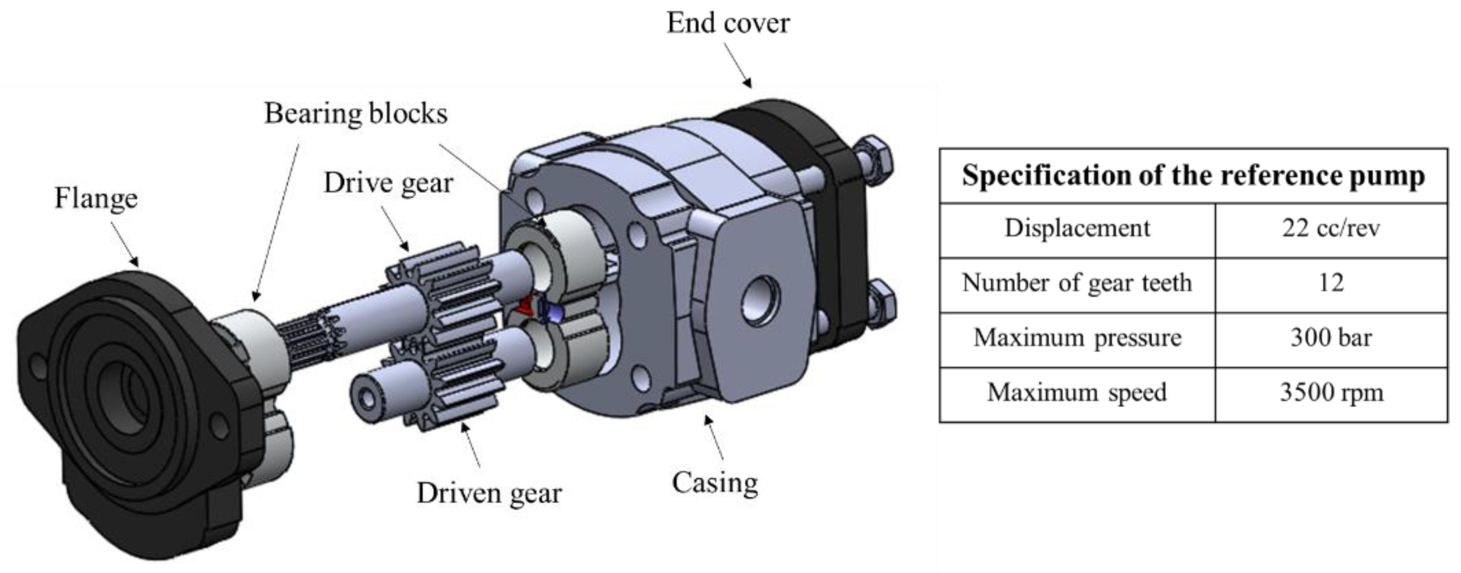
The pump under the test for this analysis is a 22 cc/ rev, 12-tooth external gear pump (EGP) for moderate- and high-pressure applications. The design includes lateral pressure-compensation, according to a well-established technology for designing external gear pumps. More details on gear pump design can be found in literature, such as [38]. The exploded view and specification of this reference pump can be seen in Figure 2. The pump is tested at the shaft speed of n r e f and the delivery pressure of p r e f where n r e f and p r e f denote the reference rotation speed and delivery pressure representative of normal use of the pump (their values are not disclosed for confidentiality reasons, but n r e f and p r e f are in the order of magnitudes of 1000 rpm and 100 bar, respectively). The fundamental pumping frequency ( f 1 , gear meshing frequency for EGP) is given by f 1 = n · z / 60 where n is the shaft speed in rpm and z is the number of pumping chamber per revolution (equal to the number of teeth for EGP). In the same way, the symbol for the i-th harmonic of the pumping frequency is denoted by f i ( = i · f 1 ) throughout the paper.

3.1. Procedures to Obtain ODS and Radiated Sound Field

3.1.1. Steady-State Operation of the Pump

The steady-state operation of the pump is an important condition to determine the ODS and radiated sound field. The steady-state operation of the pump implies maintaining a constant shaft speed as well as constant inlet and outlet pressures during the measurements. Technically, acceleration and acoustic pressure signals should be acquired simultaneously at all the measurement points. However, in most of cases, it is not practical to arrange hundreds of sensors and corresponding data acquisition systems due to physical space and cost constraints. Moreover, putting such a large number of sensors all together on the system may result in measuring a distorted vibroacoustic field (e.g., due to the high mass loading effects of accelerometers). Therefore, the measurements are performed by moving the sensors to different positions and the signals are acquired at a different time under the assumption that noise and vibration remain unchanged during the steady-state operation. To ensure the hydraulic steady-state operation, the oil temperature at the inlet is maintained constant at 50 °C under the maximum variation of ±0.5 °C using a heat exchanger, in accordance with the ISO standard of hydraulic steady-state testing [39]. In this way, the measurement is performed with minimal number of sensors, and the following results demonstrate that the vibroacoustic field does not change during the hydraulic steady-state operation.

3.1.2. Noise and Vibration Measurements

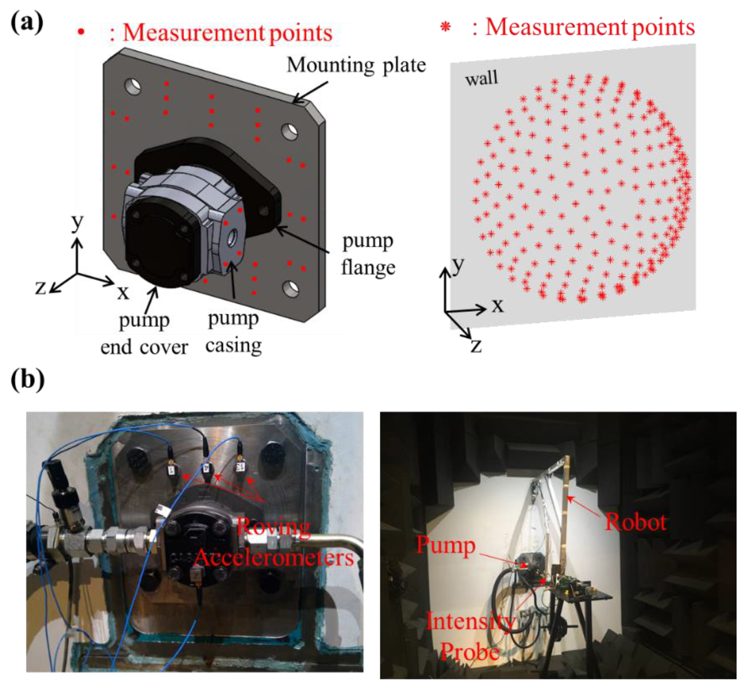
Before starting noise and vibration measurements, the measurement point locations for both the structure and the air domain should be decided. Particularly, for the air domain, a hypothetical surface enclosing the noise source on which the discrete measurement points lie should be chosen as well. In this study, hemispherical surface is chosen because it is relatively easier to interpret the results of radiated sound than other shapes as all the measurement points are at the same distance from the source. The measurement points for structural and air domain are shown in Figure 3a, and the corresponding measurement setup is shown in Figure 3b. The detailed procedures to determine the measurement points for the air domain will be discussed in Section 4.2.1. For vibration measurements, three triaxial accelerometers (PCB 356A16, PCB Piezotronics, Depew, NY, USA) are manually roved at 8 points on the inlet and outlet side of pump casing and 30 points on the mounting plate (total 114 DOFs, 3 axes/point × 38 points). To ensure that the accelerometers are positioned as correctly as possible, the corresponding measurement positions are marked on the pump and plate before they are mounted. In the air domain, the sound measurement is performed using an automated, custom-designed robot arm [40]. The robot arm moves an intensity probe composed of three microphones (Type 40A0, GRAS, Holte, Denmark) to 225 equally spaced grid points that lie on the hemispherical hypothetical surface with radius of 1 m. The pump under the test is placed at the origin of the hemisphere. Both the acceleration and the sound pressure signals are sampled at 51.2 kHz and acquired using a data acquisition system (cDAQ-9178 with NI 9234 modules, National Instruments, Austin, TX, USA) equipped with the software LabVIEW. The time length of measured signals for acceleration and sound pressure at each point is 8 s and 4 s, respectively.

3.1.3. Signal Processing of Measured Signals

Once the signals are acquired, their magnitude and relative phase information are extracted from the measured signals at each point at the frequency of interest. This process is done based on the spectral analysis. Moreover, to verify that the hydraulic steady-state operation guarantees the acoustical steady-state condition, the measurement is repeated for three times at the same points and, it is checked whether each measurement yields the same results.
(a)
Magnitude Evaluation
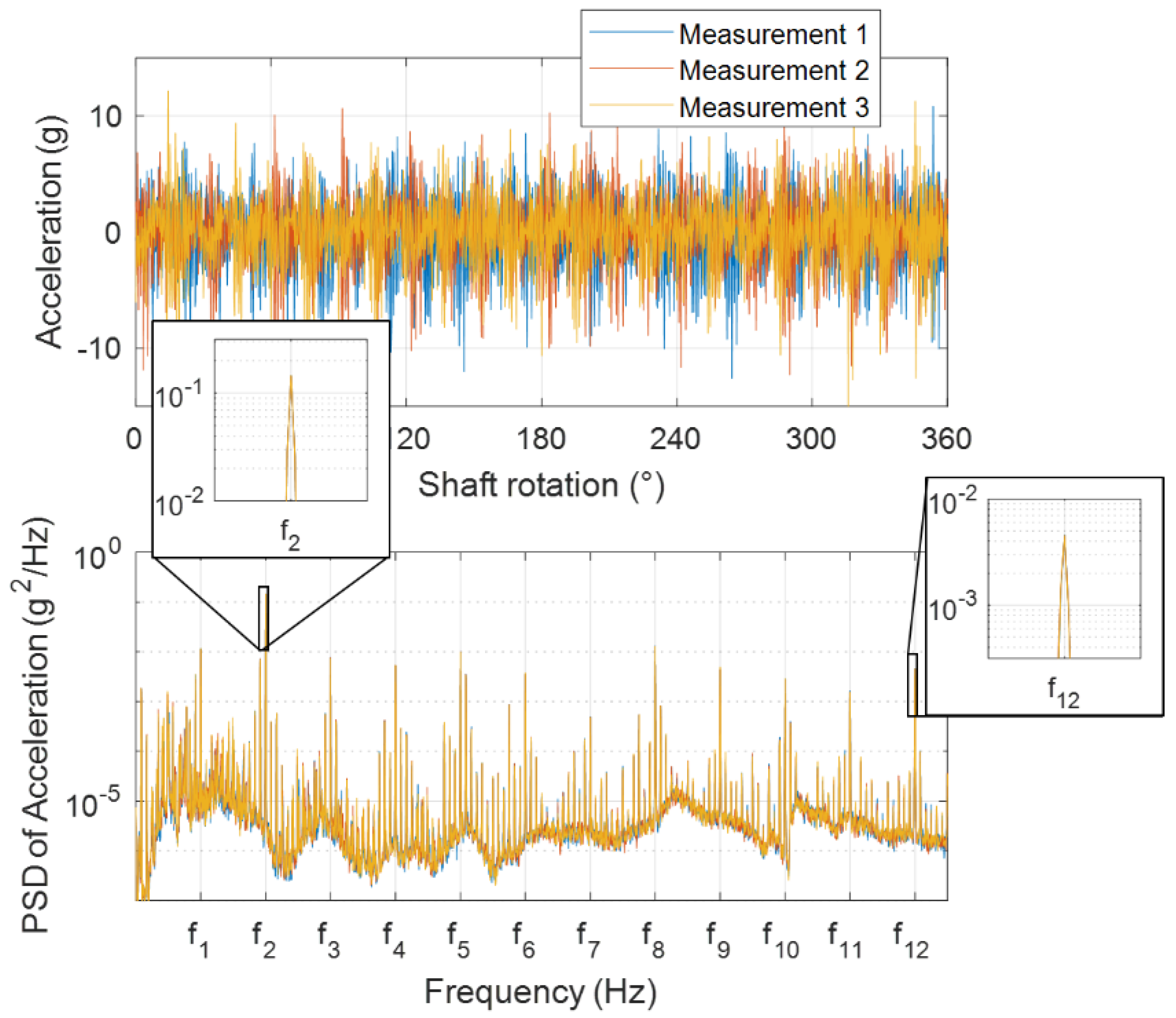
The magnitude of a frequency component is evaluated based on the power-spectral density (PSD) of signals. Figure 4 shows the measured acceleration signals at the same position at three different times (top) and their corresponding single-sided PSDs (bottom). It should be noted that the PSDs are estimated using Welch’s method with the 2 15 -sample-long Hann window and 50% overlap (averaged 24 times). It can be observed in the figure that PSD almost does not change from measurement to measurement. Especially, peak values at each harmonic of the pumping frequency (frequencies of interest) are consistent as they are completely overlapped in the zoomed-in plots. The same consistency is observed with the acoustic pressure signals. This means that the same magnitude of the frequency components always can be obtained during the steady-state operation at each point regardless of timing of the signal acquisitions.
From the estimated single-sided PSD ( G ˜ xx ( f ) ) of the signal ( x ( t ) ), the rms value ( A r m s ) of the frequency component at the particular frequency ( f a ) can be calculated as follows:
A r m s = f a q / T f a + q / T G ˜ x x ( f ) d f
where T is the time length of the window used for the estimation of PSD and q is the integer that determines the frequency interval for the integration. The choice of the integer q depends on the type of the window used for PSD estimation, and here, q = 3 is used for Hann window. Lastly, the magnitude of the frequency component is obtained by multiplying 2 to the rms value as the rms value of a unit magnitude sinusoidal signal is 1 / 2 .
(b)
Relative Phase Evaluation
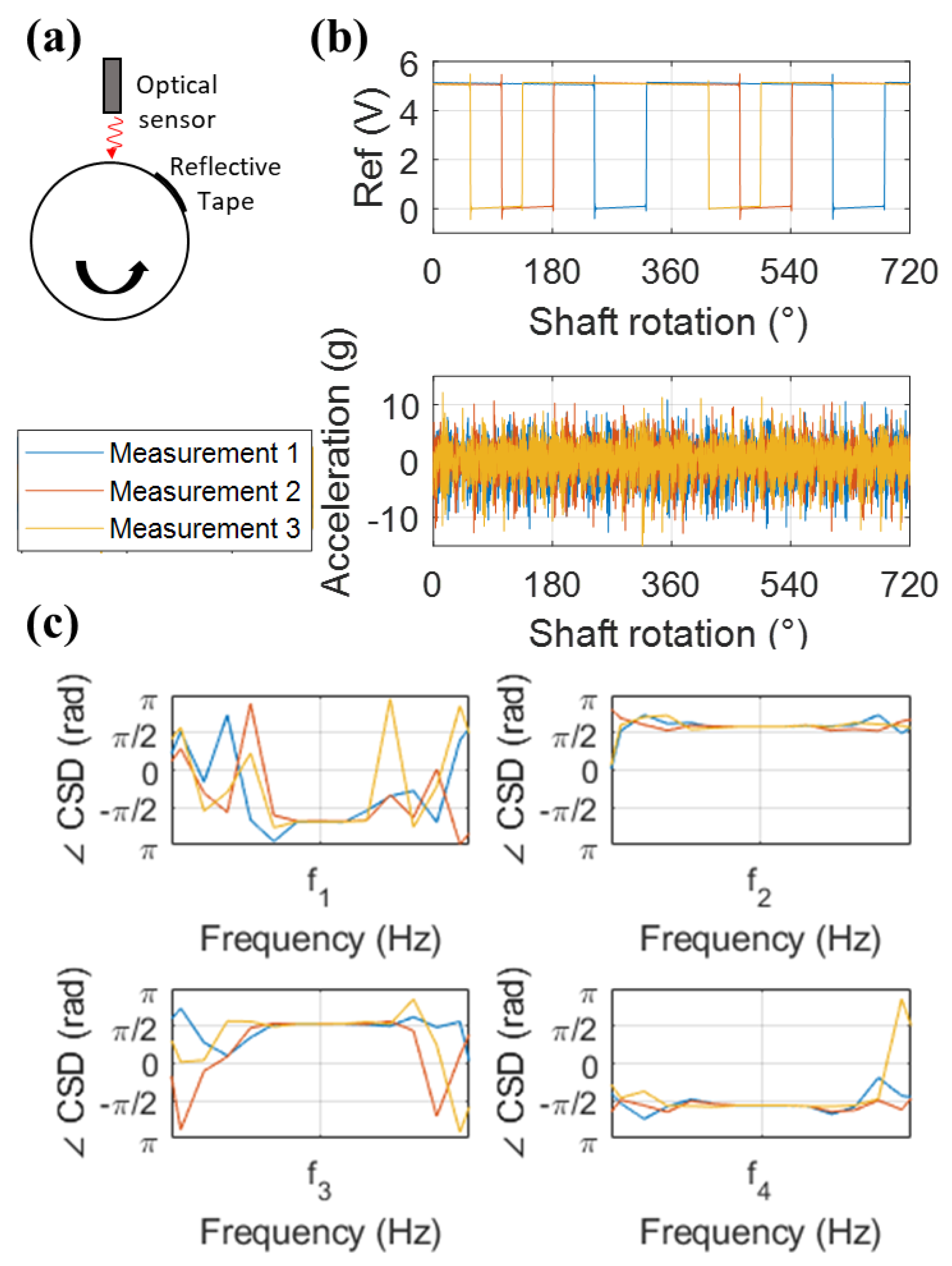
As opposed to magnitude evaluations, to obtain phase information at each point, a reference signal is needed for all the measured signals to have the same time frame. In this work, an encoder signal generated by an optical sensor is used for the reference signal. As shown in Figure 5a, a strip of reflective tape is attached on the rotating shaft, and the optical sensor generates low voltages when the sensor’s pointer is on the reflective tape and high voltages otherwise. As a result, a periodic rectangular wave is generated, whose rising (or falling) edges ensure the same angular position of the shaft rotation. This rectangular wave is recorded simultaneously at the same sampling rate at every measurement. Figure 5b shows the acceleration signals (bottom) measured at the same position at three different times along with simultaneously measured reference encoder voltage signals (top). The edges of reference voltage signals appearing at the different timing indicate that the measured acceleration signals at each measurement have a different time frame. However, the relative phase between acceleration and reference signals should be maintained at each measurement as they are simultaneously acquired. Therefore, cross-spectral density (CSD) between the response and reference signals is used to pick up the relative phase at each frequency. Note that CSDs are estimated using Welch’s method with the same parameters with PSD. Unlike PSD having real values and losing all the phase information, CSD is complex valued and the physical meaning of the phase of CSD is the phase difference between the two signals. Figure 5c shows that the phases of CSDs at each harmonic of the fundamental pumping frequency are consistent at each measurement as they are completely overlapped. In this way, all the measured signals are synchronized relative to the shaft encoder signal. Moreover, the consistency of the magnitudes and phases confirms the validity of our assumption that the vibroacoustic field remains unchanged during the steady-state operation.

3.1.4. Visualization of ODS & Radiated Sound Fields

From the magnitude ( A ^ i ( ω ) ) and relative phase ( ϕ ^ i ( ω ) ) at i -th point at the frequency ω obtained in the previous subsection, the complex-valued field variables ( ψ ^ i ( ω ) ), such as acceleration and acoustic pressure, are first established at all the measurement points as:
ψ ^ i ( ω ) = A ^ i ( ω ) e j ϕ ^ i ( ω )
Then, for ODS, the integration of accelerations with respect to time is performed by dividing j ω twice to convert them into displacements. After that, the instantaneous motions at each position over one cycle ( 0 t 2 π / ω ) are obtained by multiplying e j ω t to the complex-valued displacements and taking the real parts of them. For more effective visualizations, the linear spatial interpolation and extrapolation of vibrational motions are performed throughout the pump and mounting plate surface at each time step. In particular, the structural surface coordinate information for the interpolation and extrapolation is obtained from the CAD file of the pump. In the same way, the instantaneous acoustic pressures are obtained from complex-valued acoustic pressures and inter/extrapolated throughout the hemispherical measurement surface. Lastly, the ODSs and the radiated sound fields are visualized using the software Paraview (5.7.0-RC2, Kitware, Clifton Park, NY, USA) and MATLAB (R2019a, MathWorks, Natick, MA, USA), respectively.

3.2. Results and Discussions

3.2.1. Results and Observations

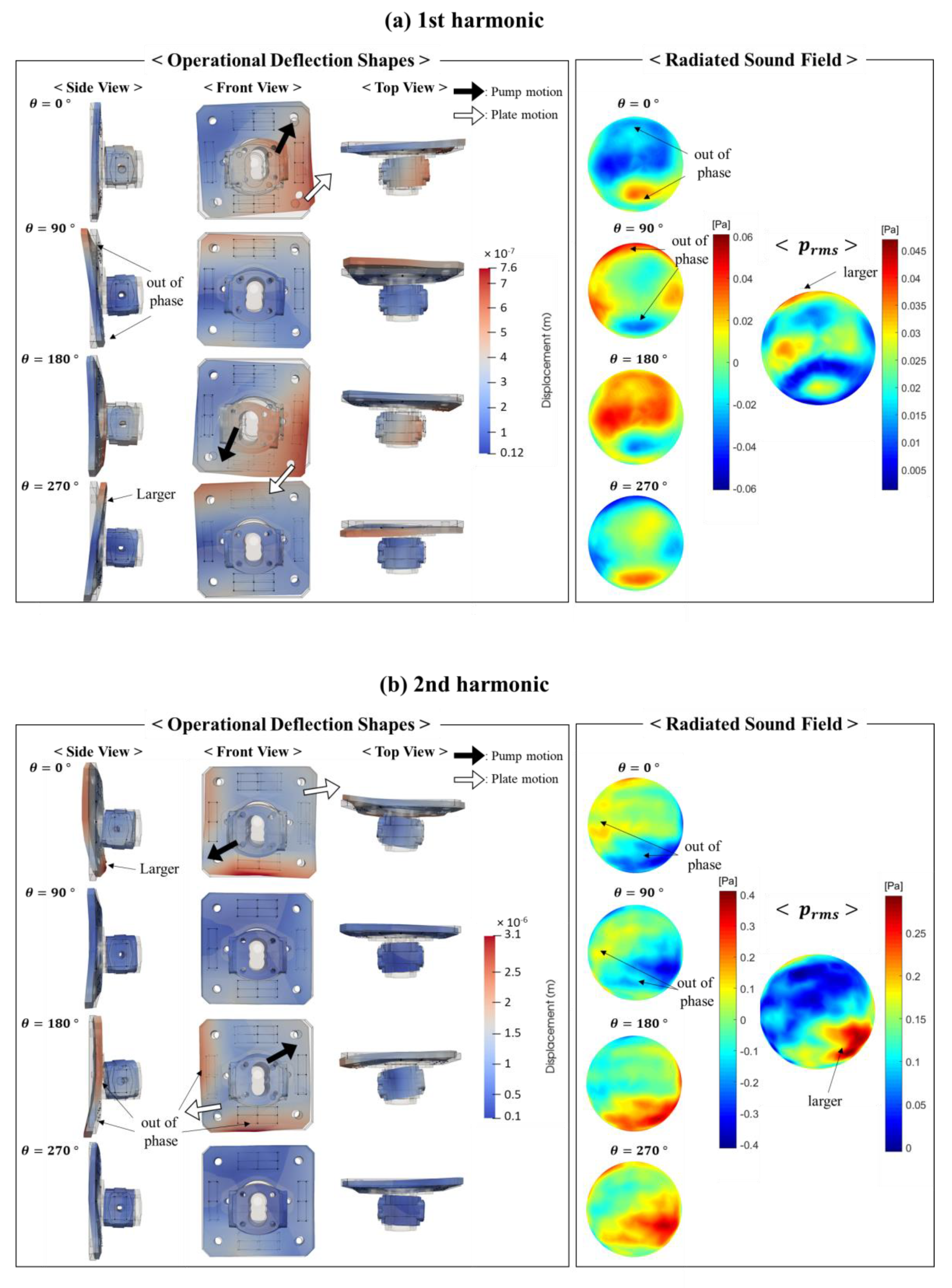
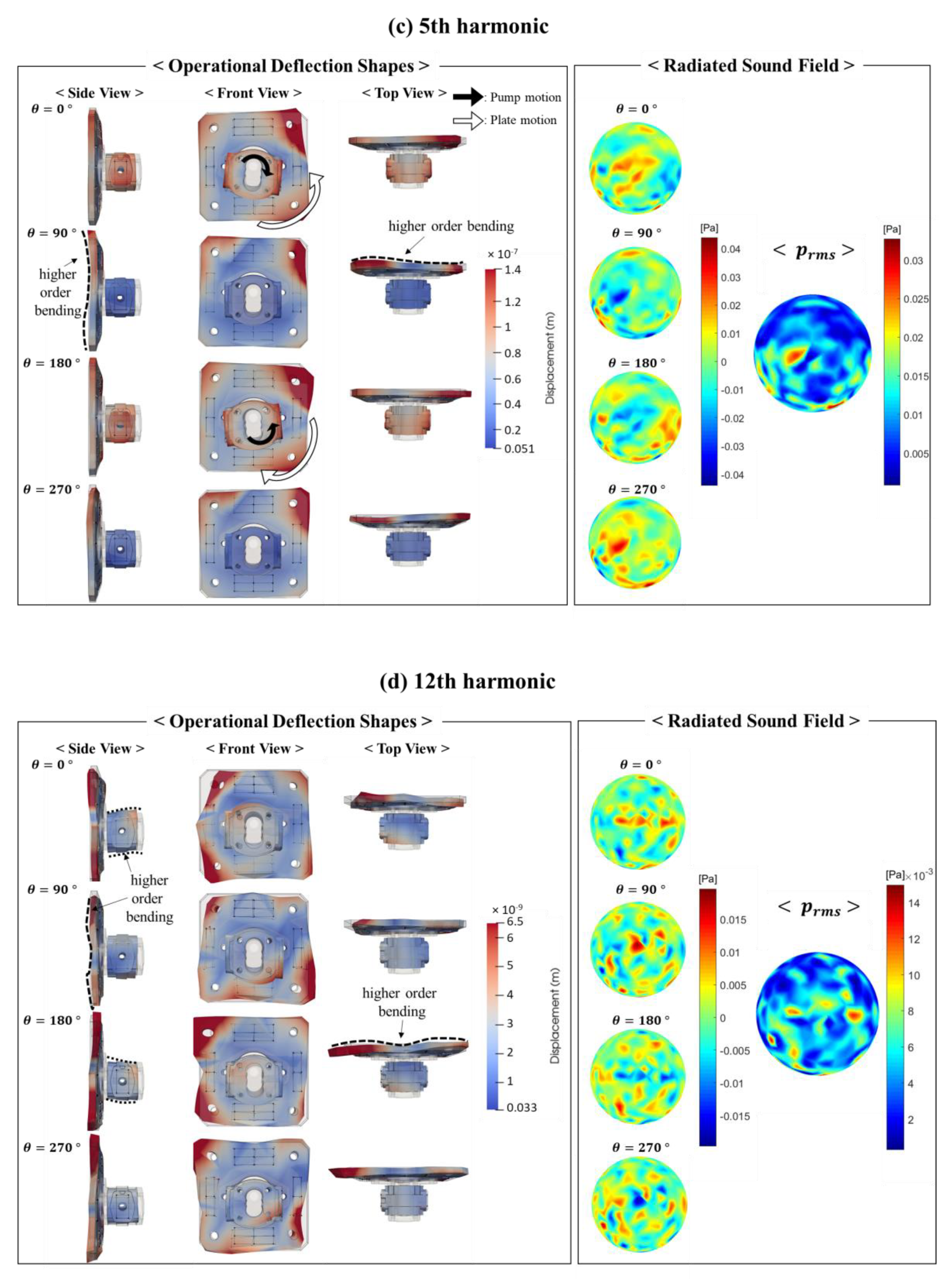
Figure 6 shows the ODS at different viewpoints and the radiated sound field at the first, second, fifth, and twelfth harmonics of the pumping frequency. The sequential snapshots at each frequency are taken over one cycle with the interval of 90° in phase. For ODS, to indicate the equilibrium positions, the structures without deflections are visualized transparently with the black lines representing feature edges. Moreover, the actual measurement positions at which the accelerometers were placed are shown with the dots connected with the wireframes. The shapes in color represent the deformed shapes due to the vibrations. Note that the deformations are exaggerated for clarity in the figure. On the right side of ODS, snapshots of instantaneous acoustic pressure over a cycle are shown with a linear color scale, along with the rms values of acoustic pressure over the hemispherical measurement surface. The measured acoustic pressure distribution can be also regarded as the noise directivity pattern because the noise measurement is conducted in the farfield.
One thing to intuitively notice in the figure is that the dominant pump and plate motions get more complicated and have higher spatial variations with increasing frequency. Regarding the pump motion, at a relatively low frequency range up to 4th harmonic, the superposition of simple horizontal and vertical bending motions is mainly observed as representatively demonstrated in the results of the 1st and 2nd harmonics. The pump has the larger vertical bending motion superposed with the smaller horizontal motion at the first harmonic whereas the larger horizontal motion is superposed with the smaller vertical bending motion at the second harmonic. Then, starting from the 5th harmonic, the torsional motion gets involved. As the frequency gets higher, the torsional motion superposed with the additional simple bending motions are observed although they are not reported in this paper for the sake of brevity. As the frequency is further increased, it is difficult to clearly distinguish the dominant pump motion due to the lack of spatial resolution. Nonetheless, the contribution of higher order bending motions appears to be involved as indicated with the dotted line in the result of 12th harmonic. The mounting plate shows the similar behavior to the pump; at the first harmonic, the dominant motion of the plate is close to the simple rocking motion at the top and bottom. As the frequency gets higher, more complicated higher order flexural motions emerge as indicated with the dashed lines in the results of the 5th and 12th harmonics.
The variation of the sound field with the frequency is also in accordance with the vibrational behaviors as it shows larger spatial variations when the frequency is higher. However, at a first glance, the noise directivity patterns in the rms plots appear to be counterintuitive when they are compared only with the dominant pump motion. If the pump motion predominantly determined the sound field, the sound field would show dipole-like behaviors mainly radiating the sound in the directions in which the dominant bending motions occur at the low frequency range such as 1st and 2nd harmonics. On the contrary, the acoustical hot spots occur almost independent of the pump bending motion directions. For example, at the 2nd harmonic, the rms values of the acoustic pressure are especially small in the diagonal direction on which the pump bending motion occurs (right-top and left-bottom regions). Moreover, the magnitudes of the noisy areas are highly asymmetric while the simple bending motions of the pump at frequencies up to 4th harmonic appear to be in the symmetric manner. Therefore, it can be concluded that the pump motion alone does not dictate the radiated sound field.
Unlike the pump motions, some correlations are observed between the plate motion and the radiated sound fields at the low frequency range. First, both the plate motion and the radiated acoustic pressure are asymmetric as opposed to the symmetric bending motions of the pump. Second, larger acoustic pressure in the rms plots is observed in the similar parts of area where the larger vibration happens in the plate. For example, at the first harmonic, the larger motion occurs on the top side of the plate, which coincides with larger acoustic pressure on the top side of the sphere. Similarly, at the second harmonic, bottom side has larger vibrational motion than the other sides, which again coincides with larger acoustic pressure on the bottom side. These instances are consistently observed at the relatively low frequency range up to 4th harmonic. The last thing they have in common can be noticed in the snapshots of the ODS and the radiated sound fields over a cycle. The out-of-phase vibrational motion and acoustic pressure occur in the similar regions of the plate and the sphere. For instance, at the first harmonic, the plate motions on the top and bottom sides are out of phase, and the out-of-phase acoustic pressures take place at the top and bottom side of the sphere over a cycle. Likewise, at the second harmonic, the left and bottom sides of both plate and sphere have the out-of-phase vibration and acoustic pressure. These observations imply that the mounting plate plays a significant role in noise radiation, and it leads to further investigation on the sound radiation by the mounting plate, as it will be discussed in the next subsection.

3.2.2. Sound Radiation by the Mounting Plate

To further investigate the contribution of the mounting plate on the sound radiation, the sound fields solely radiated by the vibrations of the mounting plate with the absence of the pumps are predicted using a simple numerical analysis. The results of this analysis are compared with the measured acoustic fields which result from the motions of both the pump and mounting. This analysis helps in better explaining the considerations made in the previous subsection.
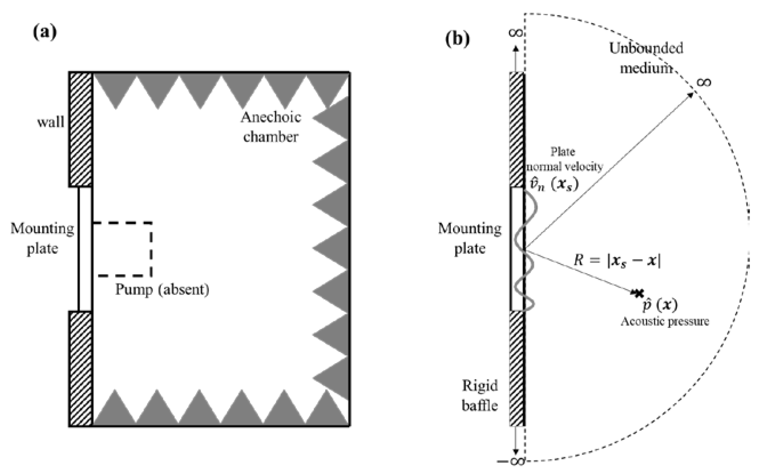
Figure 7a shows the schematic of the experimental setup inside the sound chamber and Figure 7b represents the equivalent simplified model to predict the acoustic pressure field solely radiated by the mounting plate when the pump is absent. The mounting plate without the pump is modeled as a baffled rectangular panel; the reflecting wall of the sound chamber is idealized as a rigid baffle, and the medium is assumed to be unbounded due to the anechoic environment. Since the complex-valued normal velocity fields of the plate at the frequency ω ( v ^ n   ( x s , ω ) ) are known a priori from the measurement, the resultant complex-valued acoustic pressure fields ( p ^   ( x , ω ) ) can be calculated by the well-known Rayleigh integral equation [41]:
p ^   ( x , ω ) = j ρ 0 ω 2 π S v ^ n   ( x s , ω ) e j k | x s x | | x s x | d S ( x s )  
where ρ 0 is the density of the air, k is the wavenumber, x s denotes a point on the surface of the mounting plate, and x denotes a point in the unbounded medium. Note that the signs in front of the imaginary number j in the equation are the opposite of those in [41] in which e j ω t time dependence is used whereas e j ω t time dependence is used in this work.
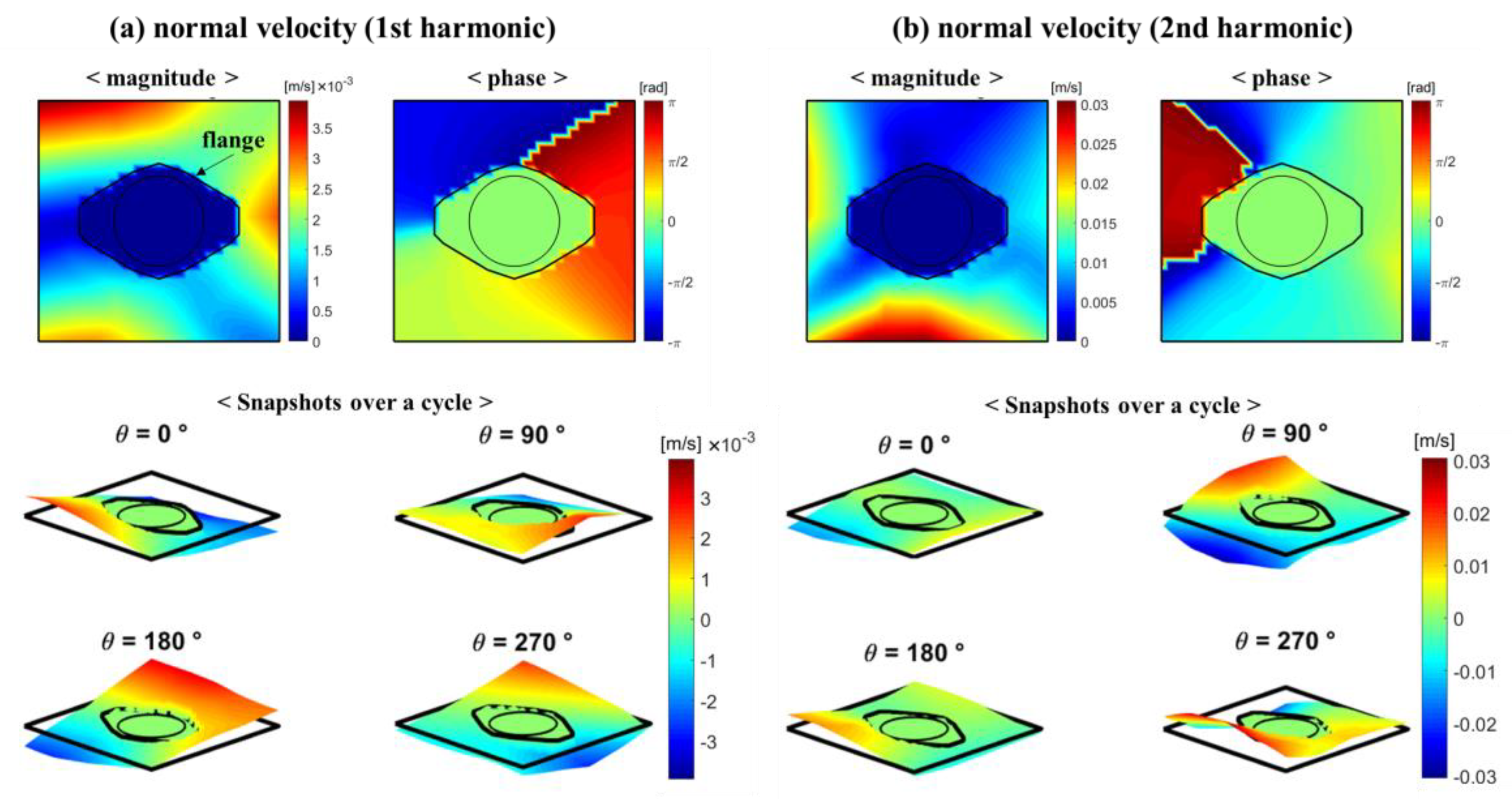
Figure 8 shows the magnitudes, phases, and snapshots over a cycle of vibration velocity normal to the mounting plate surface at the first and second harmonic, which are served as the inputs of the Rayleigh integral equation. They are obtained by extracting the complex-valued displacement components normal to the surface from ODS (in Figure 6) and converting them into the velocities by multiplying j ω . The normal velocities at the area inside the border line of the pump flange (indicated with the black solid line in the figure) are set to be zero to consider only the contribution of the plate surfaces that are directly in contact with the air on the sound radiation. Then, the acoustic pressures are calculated by feeding them into the Equation (3).
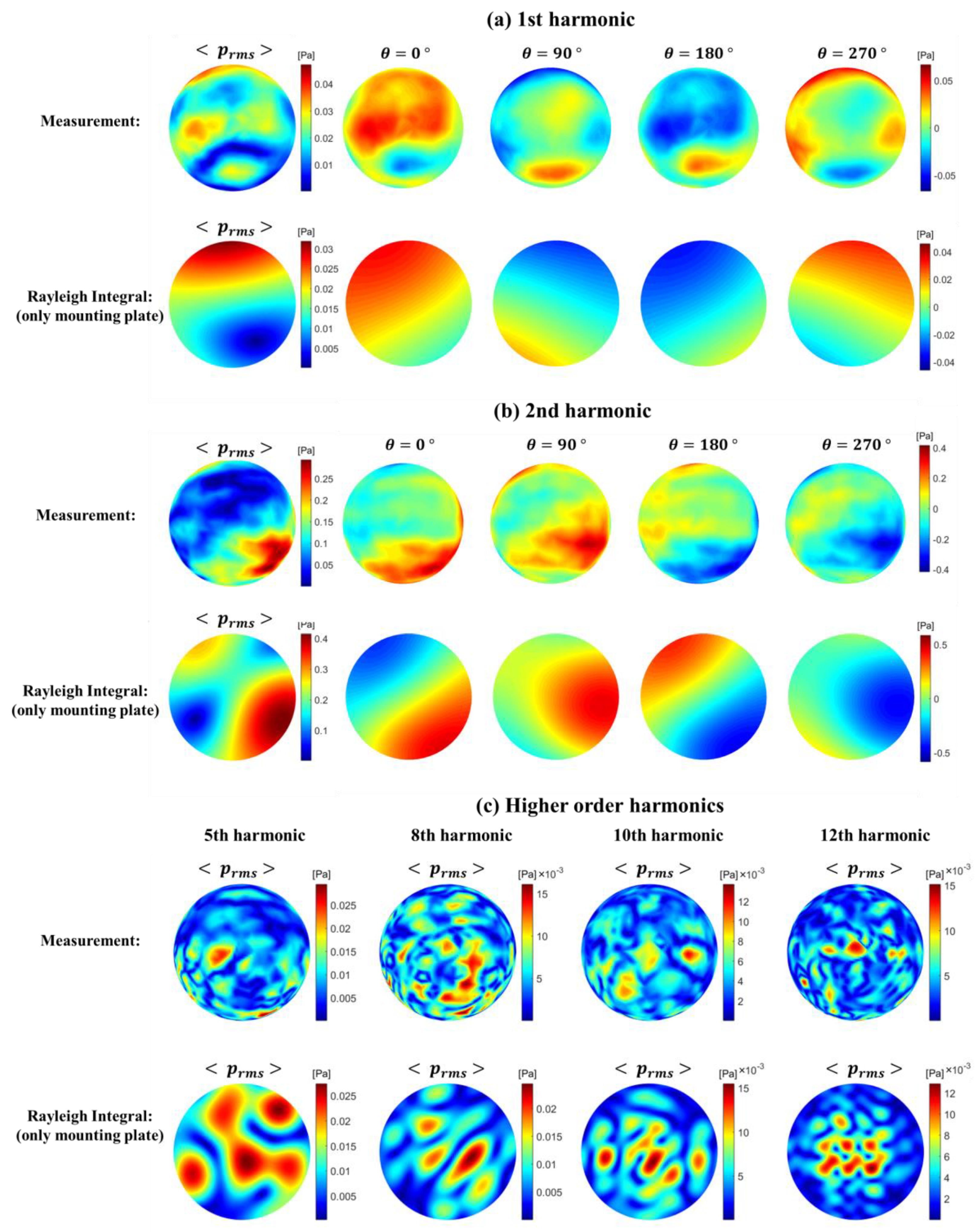
Figure 9 shows the results of acoustic pressures radiated by the only mounting plate predicted with Rayleigh integral equation and compares them with the measurement (acoustic pressures radiated by both pump and mounting plate) at different harmonics of the pumping frequency. The snapshots of acoustic pressures over a cycle at the first and second harmonics are also given in Figure 9a,b.
Some observations pertaining to the results are as follows. First, all the predicted acoustic pressures at different frequencies are in the same order of magnitude as compared to the measured acoustic pressures. Second, especially at the low frequencies such as the first and second harmonics, the rms plots and the snapshots over a cycle show similar behaviors between the measurement and prediction. Third, although some coincident noisy spots are observed between the measurement and prediction at every frequency, the degree of agreements decreases as the frequency increases. This is the expected result because the model of the Rayleigh integral equation (the pure plate radiation with the absence of the pump) is getting more deviated from the reality as, even with the noise from the pump aside, the effect of the diffraction by the actual existence of the pump increases at a higher frequency. Nonetheless, the above observations further support the fact that the mounting plate has a large contribution on the noise radiation, and that its contribution is easier to observe at the low frequency range. Lastly, the Rayleigh integral results exhibit that the mounting plate has the tendency to radiate the sound more toward the axial direction at higher frequency.

3.2.3. Discussion

Contrary to the traditional hydraulic noise research which has focused on noise sources in the fluid domain inside the unit or noise levels at some local points as explained in the introduction, this work has shown the more comprehensive approach to characterize the overall vibroacoustic behaviors of hydraulic pumps. Based on the visualized vibroacoustic fields, some observations have been provided with the support of the simple numerical analysis in the previous subsections. Some comments on the observations, the potential and the limitation of the current analysis are in the following paragraphs.
The experimental finding of the mounting plate taking an important part in noise radiation is in line with the results of previous numerical study using the combined finite element and boundary element method (FEM/BEM) done by the authors [42]. In [42], the predicted acoustic field has significantly changed and had way better agreements with the experiments after the mounting plate is considered in the simulation. This finding is reasonable because the mounting plate as a baffled panel is more likely to be an effective sound radiator than the pump as a cantilever beam so that it cannot be neglected, especially at the low frequency range. In the future, the effect of the mounting plate can be deeper studied by implementing BEM instead of Rayleigh integral equation. With BEM, the normal velocities of the pump and the mounting plate can be separately fed into the Helmholtz-Kirchhoff integral equation, and each contribution with the presence of the other component to the overall radiated noise can be assessed. In addition, it can be interesting to see how the noise radiation changes with the different mounting scenarios of numerical studies such as the different shapes, sizes, thicknesses, and materials of the mounting plate.
Furthermore, the ODS can provide useful information when modal analysis is performed as ODS appears to be the superposition of the structural modes. The similar responses, such as the simple bending motions and torsional motions, are already observed in the simulation results in [42] in which modal superposition technique is used to predict the structural response. Furthermore, it has an important implication that it can be still valid to model the hydraulic pumps as the linear system and the modal parameters play an important role in the vibration response during the operation.
The potential of this analysis is as follows. Once the clear correlation between vibration motions and noise radiation characteristics is found, noise control can be reduced to the proper vibration control. There has been an attempt to reduce the noise through active vibration control, but unfortunately, the reported noise reduction is not significant whereas the vibration level significantly decreases [37]. This is probably because the attempt was made under the simple assumption that vibration level reduction will result in the noise reduction, without a basing on the actual correlation between the structural and the acoustic domains. In this regard, understanding the vibroacoustic field behaviors and their correlations is important for more effective vibration control for noise reduction.
One limitation of the current analysis is the lack of spatial resolutions of the pump motion in ODS. This makes difficult to clearly distinguish the major motion of the pump at high frequency, as reported in the Section 3.2.1. In fact, more measurement points on the pump are desirable but were limited because the flat magnet mounting bases of accelerometers were used for roving of sensors. The pump body has limited area of smooth and flat surfaces, which are the required for flat magnet bases to provide reliable acceleration measurement. This limitation can be overcome in the future by manufacturing a special casing (e.g., parallelepiped shape with flat and smooth surfaces) or using dual rail magnet base for the curved surfaces (although it results in the decrease of operational frequency). Nonetheless, the current measurement setup still provides valuable information to understand general structural behaviors in an early phase of the study.
Another limitation is that the presented results are obtained from the measurements of a single external gear pump in a controlled laboratory test environment, so the vibroacoustic behaviors observed here may not be generalized and they may be different depending on the types of the pumps, test setups, or real applications. Nonetheless, due to the similar nature of mounting of pumps with the standardized flanges to the systems, in most of cases, the pumps are mounted as a cantilever (fixed-free ends). Thus, it is expected that the similar vibration field behaviors of pumps such as bending and torsional motions can be observed owing to the geometrical similarity (although the levels and the extents of participation of each motion will be different), and the analysis presented in this paper can be useful even with different types of hydraulic pumps and different test setups/applications. However, it would be way more difficult to find the correlation between the vibration and noise field behaviors when the acoustic environment of the system is more complicated.

4. Evaluation of Noise Performance

4.1. Sound Power Levels & Sound Pressure Levels

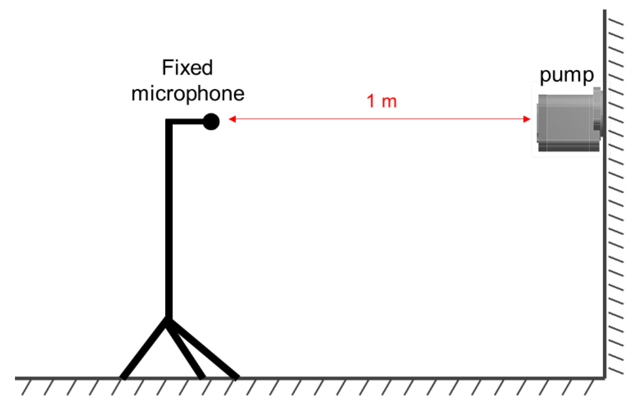
The evaluation of the noise performance of a hydraulic pump is a key aspect to be considered as the pump usually represents one of the main noise sources in hydraulic systems. In general, SWL has been traditionally used as a metric in the field of acoustics because sound power is one characteristic of the sound source and insensitive to change with the measurement environment. The ISO standards (ISO 16902-1 and ISO 4412-1) for determination of airborne noise levels of hydraulic pumps also exist [43,44], and they provide the guidelines for measuring SWLs of the pumps based on ISO 9614-1 and ISO 3744 [45,46]. However, as explained in the introduction, many hydraulic noise studies rely on simple measurements of sound pressure and acceleration at one or a few measurement points. Especially in hydraulic industry, nowadays it has become a common practice to measure simply SPLs at 1 m away from the pump as shown in Figure 10, and uses them for noise evaluation as they are commonly found in the specification sheets of hydraulic pumps provided by many manufacturers. Even though it can be a simple and cost-effective way for the evaluation, SPL changes with the measurement position and the acoustic environment (e.g., the presence of reflecting objects) and may not be the reliable metric for the fair noise evaluation in some cases. In this regard, this section provides the comparison between SWL and SPL for noise evaluation of hydraulic pumps.
Two external gear pumps with the same displacement (22 cc/rev) and the same number of gear teeth (12-tooth gears), but using a different tooth profile, are tested at 12 different operating conditions, the combination of three shaft speeds ( 1 / 2   n r e f ,   3 / 4   n r e f and n r e f in rpm) and four delivery pressures ( 1 / 4   p r e f ,   1 / 2   p r e f ,   3 / 4   p r e f and p r e f in bar). Again, n r e f and p r e f denote the reference rotation speed and delivery pressure as explained in the Section 3. Note that pump A is a non-commercial prototype with a cast iron casing used in the previous section for the characterization of the vibroacoustic field whereas pump B is the commercial one with an aluminum casing. For the determination of SWL, 225 grid points on the hemisphere are used as the same measurement points in Figure 3 in Section 3.1.2. To replicate the common practice, the SPLs measured at the closest point to the center of the hemisphere are picked up at each operating condition.
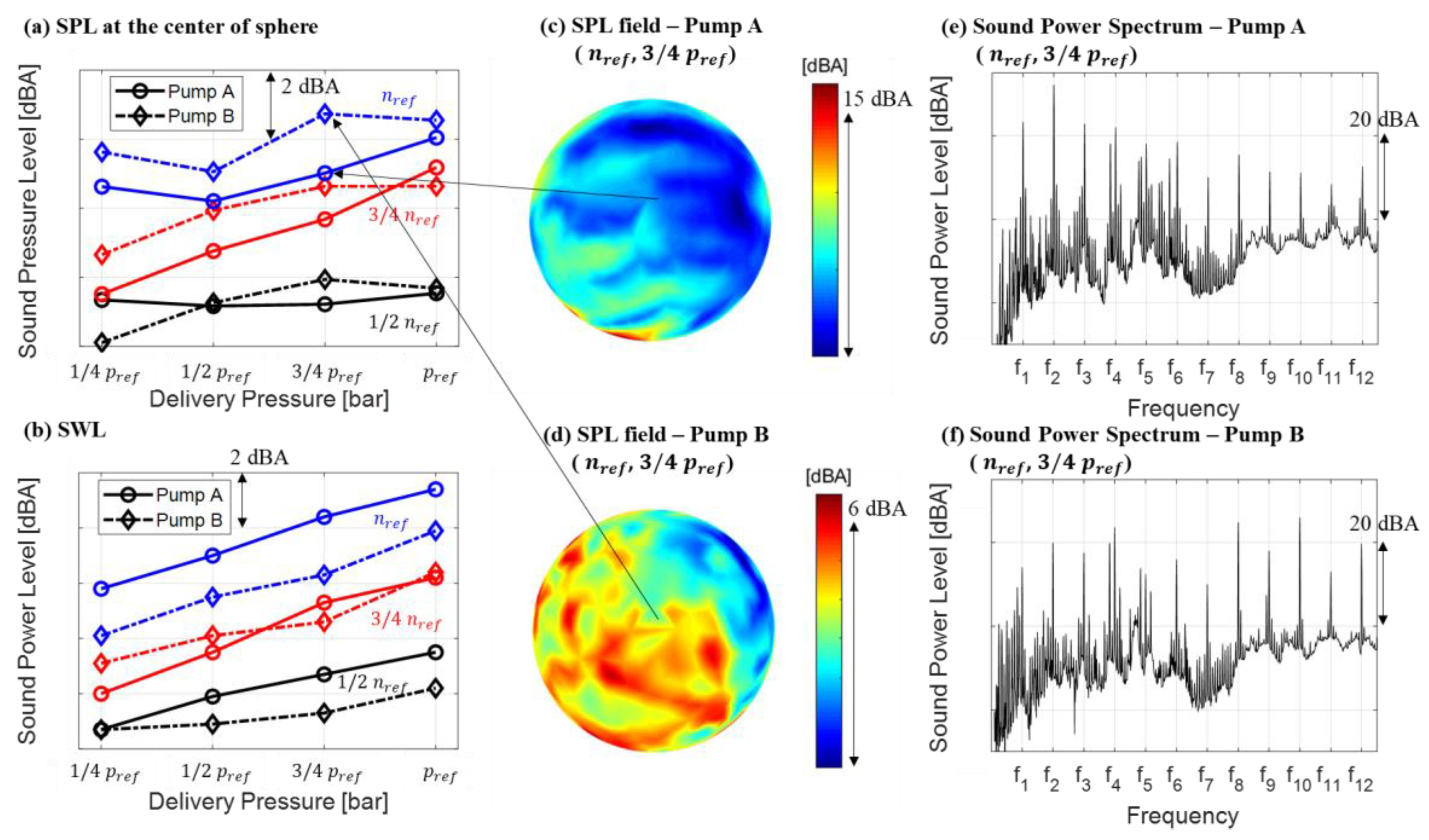
Figure 11a,b show the SPLs at the center of sphere and SWLs of pump A (circles with solid lines) and pump B (diamonds with dashed lines) at different operating conditions. If SPLs at the center of the sphere were only available data as in Figure 11a, it would be concluded that pump A is quieter than pump B as the SPLs of pump A are smaller than those of pump B at most of operating conditions. However, when SWLs are compared, the conclusion become the opposite: SWLs of pump A are higher at every operating condition except one operating condition of 3 / 4   n r e f , 3 / 4   p r e f . The justification for this result can be found by observing SPL fields of pump A (Figure 11c) and pump B (Figure 11d). Pump A radiates sounds mostly toward the peripheral area of the sphere whereas Pump B radiates loud sounds mainly toward the axial direction (despite higher spatial variations). This clear difference of noise directivity patterns can be explained with sound power spectra in Figure 11e,f along with the observations made in the Section 3.2. In the spectra, most of dominant sound energy of pump A are centered in the relatively low-frequency range (mainly at the 2nd harmonic) below the 4th harmonic while pump B has large high frequency components such as 8th and 10th harmonics. As demonstrated in ODS analysis in the previous section, the dominant motion of pump A at low frequencies would be simple bending motion along with the simple motion of the mounting plate. Thus, there is a higher chance of radiating sound mostly toward the peripheral area. On the other hand, the vibrational motion of pump B would involve the torsional motion or higher-order bending motions along with the higher bending motions of the mounting plate due to large high-frequency components, and it may make the noise radiation pattern more complicated and also have large axial radiation components.
The results provide some lessons about evaluations of noise performance of hydraulic pumps. Unless the pumps are for specific applications where the certain direction should be quiet, measuring SWLs is generally desirable for a fair noise evaluation. If measuring SWL is limited due to some constraints of the measurement setup, it is recommended to put more microphones (or move microphones) at different locations because it can significantly reduce the possibility of the wrong conclusion coming from the directivity pattern, as it will be discussed in the next section. It would be also a good practice to compare the noise spectra. If the frequencies which contain the dominant acoustic power are far different between the pumps in comparison, there is a high possibility that those pumps have greatly different noise directivity patterns, and special care may be needed.

4.2. Reliable Sound Power Measurement

The previous Section 4.1 discusses the importance of sound power determination for the noise evaluation. This section illustrates the practices that are preliminarily performed before the serious measurements in the authors’ Maha Fluid Power Research Center to ensure a reliable sound power determination. The main relevant issues for these practices concern the number of measurement points required to achieve reasonable measurement time and accuracy; and how stationary the sound field is in time, which is an essential requirement for roving the sensors. Moreover, it will be also discussed how these practices are applicable to examine the criteria of ISO 9614-1.

4.2.1. Grid Study

The necessity of a grid study is attributed to the fact that the sound field of the hydraulic pumps usually has high spatial variations. If the number of grid points is not large enough, the determined SWL may not be accurate. On the other hand, too many grid points pose challenges pertaining to the measurement time and computational cost for post processing the data. In this regard, a grid study is performed with the reference pump (pump A) to explore how the degree of accuracy of SWLs can change with the number of grid points. It is also reported whether each of the selected grid points meets the requirement and criterion of the ISO standard.
On the hemispherical hypothetical surface with the radius of 1 m, ten different sets of uniformly distributed grid points (1, 3, 6, 10, 20, 36, 50, 100, 150, and 225) are selected. The last seven sets meet the requirement of ISO 9614-1, which is 10 minimum number of grid points with the point density of 1 point / m 2 (the point density of the chosen 10 points grid is 0.63 points / m 2 , so the larger number of grid points than ten meets the requirement). The first three sets (1, 3, 6 points) smaller than 10 are included to check how accurate the SWLs can be determined with such a small number of points although it does not meet the requirement of the standard. To quantitively determine whether the chosen grid points fit the sound field’s spatial variability, the criterion of ISO 9614-1 is also examined [45]. First, the field non-uniformity indicator F 4 is calculated for each octave frequency band by dividing the standard deviations by the mean values (i.e., the normalized standard deviations) of the sound intensity measured at different positions. Then, the criterion N > C F 4 2 is assessed where N is the number of gird points and C is the factors having different values depending on the frequency bands and the grade of accuracy. Note that the ISO 9614-1 provides three grades of accuracy (survey, engineering, and precision), and the uncertainty of SWL for the survey grade is provided in the A-weighted levels (dBA) while that for the engineering and precision grade is provided in non-weighted levels (dB) at octave frequency bands.
As the main results of the grid study, the measured SWL differences from the level of the maximum grid point, the total measurement time, and the grade of accuracy achieved by each case according to the criterion of the ISO standard are tabulated in Table 2. The reason for choosing the SWL of the 225 grid points as the reference of the SWL differences is because of the assumption that the largest number of grid points provides the most accurate result. It should also be noted that the SWL for a single point is calculated by assuming the point covers the whole hemispherical area only for quantifying the uncertainties in terms of SWL. In Figure 12a, the corresponding SPL distributions are visualized on the color scale with the black dots representing the measurement positions. For the SPL distributions, the interpolation is not performed to clearly show the different number of grid points and the area that each point covers.
As shown in Table 2 and Figure 12b, the overall SWL converges to the level for the maximum grid point as the number of grid points increases. Thus, it is reasonable to assume that the largest number of grid points (225 points) can provide the most accurate SWL. Moreover, the SWL with the acceptable error (0.56 dB) can be achieved even with three points while the single point measurement has a large error (8.53 dB). Besides, the measurement time increases as the number of grid points increases but it does not increase linearly with the number of measurement points because the traveling time of the sensor from one point to other decreases as the distances between points decrease. When the criterion of the ISO standard regarding the spatial variability is checked, the first three sets (1, 3, 6 points) fail to meet the criterion of all three grades of accuracy. Interestingly, starting from 10 points, which is the minimum number of points required by the ISO standard, it satisfies the criterion for the survey grade of accuracy (the largest value of C F 4 2 is 8.58 at the octave band centered at 1 kHz, which is smaller than the number of points N = 10 ). The engineering and precision grades can be achieved starting from 36 and 100 points respectively (the largest value of C F 4 2 for N = 36 points for the engineering grade is 33.6, while the value for N = 100 points for the precision grade is 66.1, both occurring at the octave band centered at 1 kHz).
For the cases which meet the ISO standard criterion, the uncertainties of overall SWL can be evaluated based on the standard deviations for each frequency band given by the standard. The calculated uncertainty of the survey grade is ± 4   dBA (always fixed) while those of the engineering and precision grade are around ± 1.53   dB and ± 1.03   dB (these two values can vary depending on the frequency contents of the sound source). Considering that the maximum variation of SWLs from 100 points to 225 points, which achieve the precision grade of accuracy, is 0.06 dB, the uncertainty that the ISO standard provides appear to be overestimated. Similar to our findings, Carfagni [47] reported that the sound power levels from the extensive testing with difference sources exhibit much less variability than the standard deviations of the ISO standard.
Unlike the last seven sets of larger grid points, the first three sets cannot quantitively determine the degree of uncertainties based on the ISO standard as they do not meet the requirement and criterion. Nonetheless, the SWLs of 3 and 6 grid points still show the acceptable errors (−0.56 and 0.33 dB). Since it is desirable to find out the minimum number of measurement points within the acceptable range of accuracy for the practicability, further investigations are performed to quantify the uncertainties of the first three sets of grid points. The investigated uncertainty pertains to the variation of SWL depending on the configurations of the measurement positions. To this end, nine different configurations of measurement positions for three grid points and six different configurations for six grid points are arranged. The arrangement of different configurations follows the rule that the measurement positions should be distributed as uniformly as possible on the hemispherical surface. Then, the sound intensity is taken from 225-grid-point results at the closest points from each configuration, and SWLs are determined by integrating them over the surface area. For the single point measurement, it is assumed that any of the 225 points can be the possible candidate in practice and the single point covers the whole surface area. The obtained uncertainties are displayed with the error bar in Figure 12b, and the SPL distributions and the measurement positions that bring about the minimum, median, and maximum SWLs are shown in Figure 12c. It should be noted again that the error bar in Figure 12b simply represents the range of variations in SWLs for each set of the grid points, not the statistical standard deviations as in the ISO standard. It can be seen that the range of variations in SWLs decreases as the number of grid points increases; the ranges of variations are from −10.2 dB to 6.4 dB for the single point, from −1.3 dB to 1.6 dB for the three points, and from −1.1 dB to 0.7 dB for the six points. The results highlight that the range of uncertainties can be significantly reduced even with the three-point measurement compared to the single point measurement.
Perhaps, a safe way to determine the reliable sound power as a metric for the assessment of the noise performance would be according to the standards. However, it sometimes may be impractical to follow all the required procedures for the technical and cost reasons. In this case, deciding the number of measurement points when planning the noise measurements may not be straightforward, so the grid study is recommended to be preliminarily performed to reduce the uncertainties of the determined sound power coming from the spatial variability of the sound field. This can be viewed as the analogous of a mesh convergence study of a finite element analysis, in which the reasonable mesh size is determined by observing the convergence of physical variables depending on the mesh size. Then, based on the results of the grid study, the reasonable number of grid points can be decided depending on the purpose of the measurement. For example, if the purpose is to thoroughly investigate the radiated noise field along with the determination of precise SWLs like the analysis in the Section 3, the noisy spots, such as the dark red spot on the top part of the sphere which is not captured up to 50 points in Figure 12a, should not be missed. In this case, more than 100 points, which also turned out to achieve the precision grade of the ISO standard in our study, may be preferable. On the other hand, if many pumps need to be tested and compared at a large number of operating conditions, the measurement time would be an important factor and the detailed noise radiation patterns might not be of great interest. In this case, our results suggest that the number of measurement points can be reduced as low as three points within the acceptable range of variations (around ±1.5 dB difference from the level of 225 points). Although this result cannot be generalized for the applications of all the hydraulic pump noise measurement, one clear and important lesson is that the single point measurement as shown in Figure 10. Simple measurement of sound pressure level at the distance of 1 m from the pump can introduce a large uncertainty for the assessment of hydraulic pump noise performances whereas a few additional points can dramatically decrease this uncertainty.

4.2.2. Repeatability Test

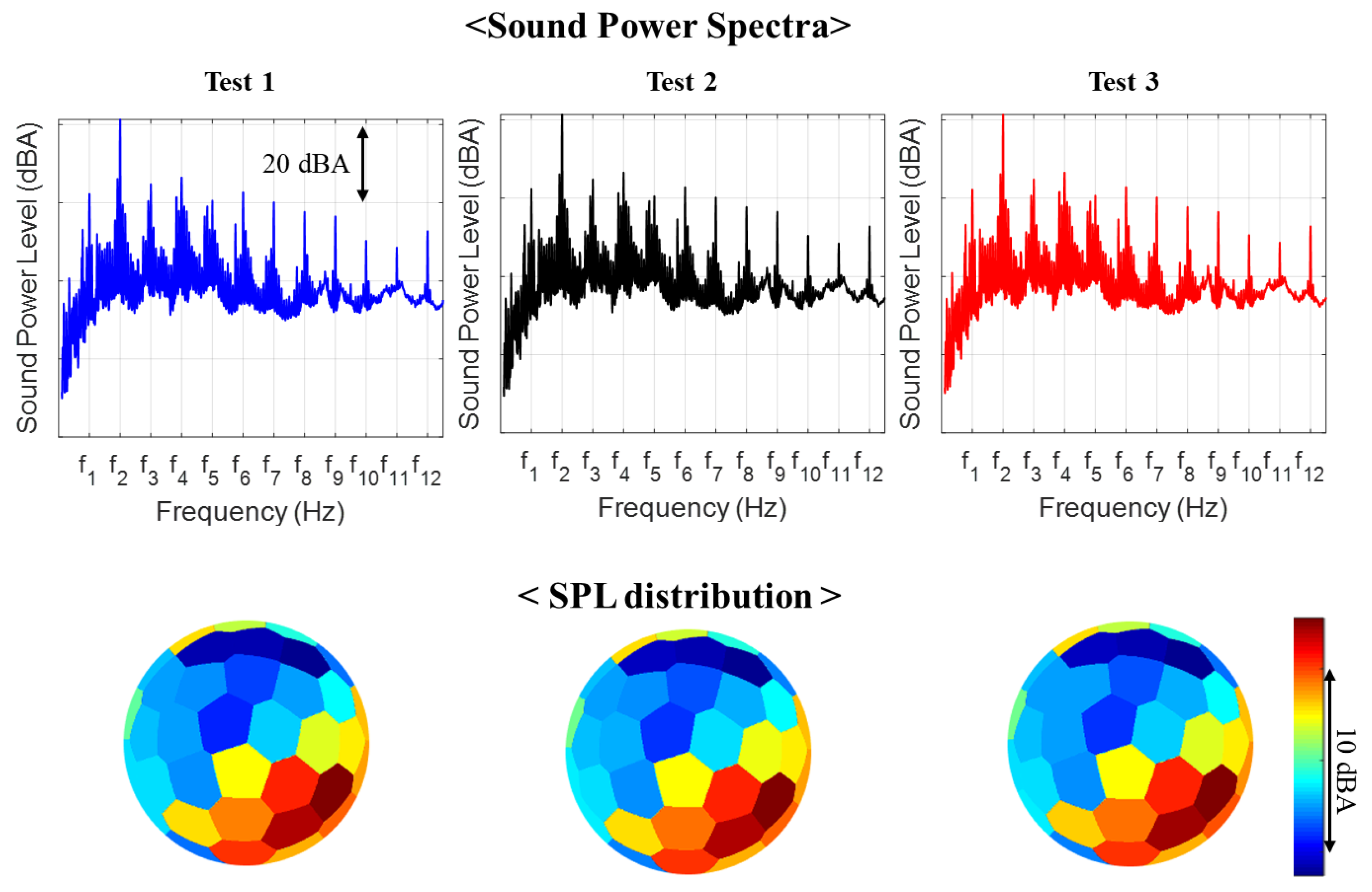
Although it was shown the noise and vibration of hydraulic pumps generally remain unchanged under the steady-state operation as shown in Section 3, it is still a good practice to ensure the repeatability of the tests. Since checking the repeatability does not require fine details of sound fields and the high grade of accuracy, 36 grid points are used for the test. As explained before, this is enough to meet the requirement of the engineering grade (grade 2) according to ISO 9614-1. The measurements are repeated with pump A for three times for the example chosen in this paper. Similar to the grid study, SWL variations with respect to the level for the test 1 (first test) are tabulated in Table 3, and corresponding sound power spectra and SPL distributions are shown in Figure 13. It can be seen that the sound power spectra, SPL distributions, and SWLs remain almost unchanged at each measurement, and the maximum SWL variance is 0.012 dBA as shown in the table. The results confirm the good repeatability and reliability of SWLs and reassure the validity of steady-state assumption.
In essence, the purpose of the repeatability test is to examine whether the sound field to be measured is stationary in time, which is the essential characteristics of the sound field for roving the sensors. For the assessment of whether the sound field is stationary, the ISO standard suggests choosing a typical measurement point and calculating the temporal variability indicator F 1 at that point. Then, the criterion F 1 < 0.6 needs to be checked. Following the standard, the indicator F 1 is calculated at three positions by measuring the noise for ten times at each position: the center of the sphere as a typical measurement point as the standard suggests and two additional positions where the maximum and minimum SPLs occur. Similar to the field non-uniformity indicator F 4 in Section 4.2.1, the temporal variability indicator F 1 is evaluated by dividing the standard deviation by the mean value (i.e., the normalized standard deviation) of repeatedly measured sound intensities at the fixed points. The calculated values of F 1 are 0.1 at the center, 0.04 at the location of maximum SPL, and 0.03 at the location of minimum SPL. The criterion is met with the values of F 1 far less than 0.6 at all the three positions in our test, which quantitively confirms that the sound field of our reference pump is stationary in time. However, this result implies that the indicator F 1 also can vary with the position. Thus, to ensure whether the sound field is stationary enough in time, it would be also a good practice to check the values of F 1 at different positions or perform a repeatability test as shown in this section. If either the indicator F 1 or the repeatability test shows that the sound field of hydraulic pumps is not stationary enough in time, the possible actions to take to mitigate the temporal variability can be reducing the degree of cavitation or keeping the inlet temperature as constant as possible, which are the common causes of the temporal variability of the hydraulic pump noise.

5. Conclusions

This paper discusses the experimental investigation of vibroacoustic fields and evaluation of noise performance of hydraulic pumps. Both topics require a large number of measurement positions in space, and the technique proposed in this paper uses only one intensity probe and a set of three tri-axial accelerometers, which are roved under the steady-state condition. The results show that the vibroacoustic remains stationary in time once the hydraulic steady-state is achieved.
For ODS and the corresponding radiated sound field, PSD and CSD with a shaft encoder signal are used for evaluating magnitude and the relative phase. By properly mapping and interpolating the magnitudes and phases at each point, the snapshots of vibroacoustic field taken over a cycle are visualized. Taking as reference the case of an external gear pump, some interesting observations are made from the visualized fields as follows:
  • As the frequency increases, the dominant pump body motion becomes the superposition of more complicated motions in the following order: simple horizontal and vertical bending, torsion, and the higher order bending. Similarly, the motion of the mounting plate and acoustic field have larger spatial variations at the higher frequency.
  • At low frequencies, noisy area exists independent of the direction where the pump bending motion takes place. Furthermore, while the pump bending motions appear quite symmetric, noise radiation pattern is asymmetric at the low frequency range. It concludes that the motion of the pump does not predominantly dictate the sound field.
  • The acoustic field and the motions of the mounting plate have several things in common at the low frequencies. First, both of their distributions are in an asymmetric manner. Second, the rms magnitudes of acoustic pressures are larger in the similar region in which the larger deflections of the mounting plate occur. Third, the similar out-of-phase behaviors of the plate motion and the acoustic pressure are observed in the similar regions of the plate and hemispherical acoustic measurement surface.
To further investigate the contribution of the mounting plate on the resultant noise field, the Rayleigh integral is performed only with the normal velocities of the mounting plate. The computed sound fields show similar noisy area and similar behaviors over a cycle of the measured sound fields, especially at low frequencies. This result highlights that the mounting plate plays a significant role in noise radiation. Some supporting explanations regarding the observations and potentials of this analysis are also discussed as well as the limitation of the current study.
Lastly, for the noise performance evaluation, SWL and SPL are compared. The results show that the noise evaluation based on SPL at a single point can be misleading because noisy directivity patterns can be different from pump to pump. Therefore, in general, it is more desirable to measure SWL for the fair assessment of the noise performances of the hydraulic pumps. In addition, grid study and repeatability test are discussed to have the reliable sound power determination. The grid study results show that at least ten points are required to achieve the lowest grade of accuracy according to ISO 9614-1. The further analysis is also performed to investigate the minimum number of grid points, and the results highlight that, for the reference pump, even three points measurement can provide the SWL within the reasonable uncertainty (around ±1.5 dB variations) whereas the single point measurement exhibits the large range of SWL variation (from −10.2 dB to 6.4 dB). As a way to check if the sound field of the pump is stationary in time, the example of repeatability test is introduced, in which the negligible differences of SWLs, sound power spectra, and SPL distributions between measurements are observed, and the ways to mitigate the temporal variability of the hydraulic pumps are discussed.

Author Contributions

Conceptualization, S.W. and A.V.; methodology, S.W. and A.V.; software, S.W. and A.V.; validation, S.W. and A.V.; formal analysis, S.W.; investigation, S.W.; resources, A.V.; data curation, S.W.; writing—original draft preparation, S.W.; writing—review and editing, S.W. and A.V.; visualization, S.W.; supervision, A.V.; project administration, A.V. All authors have read and agreed to the published version of the manuscript.

Funding

This research received no external funding.

Acknowledgments

The authors would like to thank Manuel Rigosi and Antonio Lettini of the R&D department of Casappa S.p.A., Italy, for providing the physical units and technical information.

Conflicts of Interest

The authors declare no conflict of interest.

References

  1. Ge, L.; Quan, L.; Zhang, X.; Zhao, B.; Yang, J. Efficiency improvement and evaluation of electric hydraulic excavator with speed and displacement variable pump. Energy Convers. Manag. 2017, 150, 62–71. [Google Scholar] [CrossRef]
  2. Naayagi, R.T. A review of more electric aircraft technology. In Proceedings of the 2013 International Conference on Energy Efficient Technologies for Sustainability (ICEETS 2013), Nagercoil, India, 10–12 April 2013; pp. 750–753. [Google Scholar]
  3. Korane, K. Electrification Exposes Hydraulic-Pump Shortcomings. Available online: https://www.fluidpowerworld.com/electrification-exposes-hydraulic-pump-shortcomings/ (accessed on 15 December 2020).
  4. Edge, K. Designing quieter hydraulic systems—Some recent developments and contributions. Proc. JFPS Int. Symp. Fluid Power 1999, 1999, 3–27. [Google Scholar] [CrossRef]
  5. Pettersson, M.E.; Weddfelt, K.G.; Palmberg, J.O.S. Methods of reducing flow ripple from fluid power piston pumps—An experimental approach. SAE Tech. Pap. 1991, 100, 158–167. [Google Scholar] [CrossRef]
  6. Kojima, E.; Yu, J.; Ichiyanagi, T. Experimental determining and theoretical predicting of source flow ripple generated by fluid power piston pumps. SAE Trans. 2000, 109, 348–357. [Google Scholar]
  7. Drew, J.E.; Longmore, D.K.; Johnston, D.N. Theoretical analysis of pressure and flow ripple in flexible hoses containing tuners. Proc. Inst. Mech. Eng. Part I J. Syst. Control. Eng. 1998, 212, 405–422. [Google Scholar] [CrossRef]
  8. Johnston, D.N.; Drew, J.E. Measurement of positive displacement pump flow ripple and impedance. Proc. Inst. Mech. Eng. Part I J. Syst. Control. Eng. 1996, 210, 65–74. [Google Scholar] [CrossRef]
  9. Kalbfleisch, P.K.; Ding, D.; Baruah, A.; Ivantysynova, M.; Franzoni, G.; Zhang, H. Swashplate plate type axial piston pump noise diagnostics for design. In Proceedings of the Sixteenth Scandinavian International Conference on Fluid Power, Tampere, Finland, 22–24 May 2019. [Google Scholar]
  10. Ivantysynova, M.; Huang, C.; Christiansen, S.K. Computer aided valve plate design—An effective way to reduce noise. SAE Tech. Pap. 2004, 113, 162–173. [Google Scholar]
  11. Seeniraj, G.K.; Ivantysynova, M. Impact of valve plate design on noise, volumetric efficiency and control effort in an axial piston pump. In Proceedings of the American Society of Mechanical Engineers, The Fluid Power and Systems Technology Division (FPST), Chicago, IL, USA, 5–10 November 2006; American Society of Mechanical Engineers (ASME): New York, NY, USA, 2006; pp. 77–84. [Google Scholar]
  12. Ye, S.G.; Zhang, J.H.; Xu, B. Noise reduction of an axial piston pump by valve plate optimization. Chin. J. Mech. Eng. 2018, 31, 57. [Google Scholar] [CrossRef] [Green Version]
  13. Devendran, R.S.; Vacca, A. Optimal design of gear pumps for exhaust gas aftertreatment applications. Simul. Model. Pr. Theory 2013, 38, 1–19. [Google Scholar] [CrossRef]
  14. Manring, N.D.; Kasaragadda, S.B. The theoretical flow ripple of an external gear pump. J. Dyn. Syst. Meas. Control 2003, 125, 396. [Google Scholar] [CrossRef]
  15. Ransegnola, T.; Zhao, X.; Vacca, A. A comparison of helical and spur external gear machines for fluid power applications: Design and optimization. Mech. Mach. Theory 2019, 142, 103604. [Google Scholar] [CrossRef]
  16. Devendran, R.S.; Vacca, A. Design potentials of external gear machines with asymmetric tooth profile. In Proceedings of the ASME/BATH 2013 Symposium on Fluid Power and Motion Control (FPMC 2013), Sarasota, FL, USA, 6–9 October 2013; American Society of Mechanical Engineers (ASME): New York, NY, USA, 2013. [Google Scholar]
  17. Zhao, X.; Vacca, A. Analysis of continuous-contact helical gear pumps through numerical modeling and experimental validation. Mech. Syst. Signal. Process. 2018, 109, 352–378. [Google Scholar] [CrossRef]
  18. Nagamura, K.; Ikejo, K.; Tutulan, F.G. Design and performance of gear pumps with a non-involute tooth profile. Proc. Institution Mech. Eng. Part B J. Eng. Manuf. 2004, 218, 699–711. [Google Scholar] [CrossRef]
  19. Mucchi, E.; Dalpiaz, G.; Fernandez del Rincon, A. Elastodynamic analysis of a gear pump. Part I: Pressure distribution and gear eccentricity. Mech. Syst. Signal. Process. 2010, 24, 2160–2179. [Google Scholar] [CrossRef]
  20. Borghi, M.; Paltrinieri, F.; Milani, M.; Zardin, B. The influence of cavitation and areation on gear pumps and motors meshing volumes pressures. In Proceedings of the American Society of Mechanical Engineers, The Fluid Power and Systems Technology Division (FPST), Chicago, IL, USA, 5–10 November 2006; American Society of Mechanical Engineers (ASME): New York, NY, USA, 2006; pp. 47–56. [Google Scholar]
  21. Edge, K.A.; Lipscombe, B.R. The reduction of gear pump pressure ripple. Proc. Inst. Mech. Eng. Part B Manag. Eng. Manuf. 1987, 201, 99–106. [Google Scholar] [CrossRef]
  22. Woo, S.; Opperwall, T.; Vacca, A.; Rigosi, M. Modeling noise sources and propagation in external gear pumps. Energies 2017, 10, 1068. [Google Scholar] [CrossRef] [Green Version]
  23. Mucchi, E.; Rivola, A.; Dalpiaz, G. Modelling dynamic behaviour and noise generation in gear pumps: Procedure and validation. Appl. Acoust. 2014, 77, 99–111. [Google Scholar] [CrossRef]
  24. Opperwall, T.; Vacca, A. A combined FEM/BEM model and experimental investigation into the effects of fluid-borne noise sources on the air-borne noise generated by hydraulic pumps and motors. Proc. Inst. Mech. Eng. Part C J. Mech. Eng. Sci. 2014, 228, 457–471. [Google Scholar] [CrossRef]
  25. Carletti, E.; Miccoli, G.; Pedrielli, F.; Parise, G. Vibroacoustic measurements and simulations applied to external gear pumps. An integrated simplified approach. Arch. Acoust. 2016, 41, 285–296. [Google Scholar] [CrossRef] [Green Version]
  26. Tang, C.; Wang, Y.S.; Gao, J.H.; Guo, H. Fluid-sound coupling simulation and experimental validation for noise characteristics of a variable displacement external gear pump. Noise Control. Eng. J. 2014, 62, 123–131. [Google Scholar] [CrossRef]
  27. Pan, Y.; Li, Y.; Huang, M.; Liao, Y.; Liang, D. Noise source identification and transmission path optimisation for noise reduction of an axial piston pump. Appl. Acoust. 2018, 130, 283–292. [Google Scholar] [CrossRef]
  28. Rodionov, L.; Makaryants, G. Simulation of gear pump noise generation. In Proceedings of the 9th FPNI Ph.D. Symposium on Fluid Power, Florianópolis, Brazil, 26–28 October 2016; pp. 1–9. [Google Scholar]
  29. Schleihs, C.; Murrenhoff, H. Acoustical simulation of a hydraulic swash plate motor. In Proceedings of the ASME/BATH 2015 Symposium on Fluid Power and Motion Control (FPMC 2015), Chicago, IL, USA, 12–14 October 2015. [Google Scholar]
  30. Bonanno, A.; Pedrielli, F. A study on the structureborne noise of hydraulic gear pumps. Proc. JFPS Int. Symp. Fluid Power 2008, 2008, 641–646. [Google Scholar] [CrossRef]
  31. Zhang, J.; Xia, S.; Ye, S.; Xu, B.; Song, W.; Zhu, S.; Tang, H.; Xiang, J. Experimental investigation on the noise reduction of an axial piston pump using free-layer damping material treatment. Appl. Acoust. 2018. [Google Scholar] [CrossRef]
  32. Wang, H.; Cao, S.; Luo, X.; He, X.; Zhang, Z.; Zhu, Y. Study on the influence of rubber isolator’s dynamic stiffness on the dynamic behavior of seawater hydraulic piston pump. Ocean Eng. 2019, 182, 14–20. [Google Scholar] [CrossRef]
  33. Xu, B.; Ye, S.; Zhang, J. Numerical and experimental studies on housing optimization for noise reduction of an axial piston pump. Appl. Acoust. 2016, 110, 43–52. [Google Scholar] [CrossRef]
  34. Zhang, J.; Xia, S.; Ye, S.; Xu, B.; Zhu, S.; Xiang, J.; Tang, H. Experimental investigation on the sharpness reduction of an axial piston pump with reinforced shell. Appl. Acoust. 2018, 142, 36–43. [Google Scholar] [CrossRef]
  35. Rodionov, L.; Rekadze, P. Exploration of acoustic characteristics of gear pumps with polymeric pinion shafts. Procedia Eng. 2015, 106, 36–45. [Google Scholar] [CrossRef] [Green Version]
  36. Kim, T.; Ivantysynova, M. Active vibration control of swash plate-type axial piston machines with two-weight notch least mean square/filtered-x least mean square (LMS/FxLMS) filters. Energies 2017, 10, 645. [Google Scholar] [CrossRef] [Green Version]
  37. Kim, T.; Ivantysynova, M. Active vibration/noise control of axial piston machine using swash plate control. In Proceedings of the ASME/BATH 2017 Symposium on Fluid Power and Motion Control (FPMC 2017), Sarasota, FL, USA, 16–19 October 2017; American Society of Mechanical Engineers: New York, NY, USA, 2017. [Google Scholar]
  38. Ivantysyn, J.; Ivantysynova, M. Hydrostatic Pumps and Motors: Principles, Design, Performance, Modelling, Analysis, Control and Testing; Tech Books International Pvt. Ltd.: Maharashtra, India, 2003. [Google Scholar]
  39. Hydraulic Fluid Power: Positive-Displacement Pumps, Motors and Integral Transmissions: Methods of Testing and Presenting Basic Steady-State Performance; ISO 4409; International Organization for Standardization: Geneva, Switzerland, 2007.
  40. Kalbfleisch, P.; Kim, T.; Ivantysynova, M. Robotic arm for automatic sound intensity measurements. In Proceedings of the BATH/ASME 2016 Symposium on Fluid Power and Motion Control (FPMC 2016), Bath, UK, 7–9 September 2016; American Society of Mechanical Engineers: New York, NY, USA, 2016. [Google Scholar]
  41. Pierce, A.D. Acoustics: An Introduction to its Physical Principles and Applications; The Acoustical Society of America: Melville, NY, USA, 1989. [Google Scholar]
  42. Woo, S.; Vacca, A.; Rigosi, M. A model based approach for the evaluation of noise emissions in external gear pumps. In Proceedings of the 11th International Fluid Power Conference (IFK), Aachen, Germany, 19–21 March 2018. [Google Scholar]
  43. Hydraulic Fluid Power—Test Code for the Determination of Sound Power Levels of Pumps Using Sound Intensity Techniques: Engineering Method—Part 1: Pumps; ISO 16902-1; International Organization for Standardization: Geneva, Switzerland, 2003.
  44. Hydraulic Fluid Power—Test Code for Determination of Airborne Noise Levels—Part 1: Pumps; ISO 4412-1; International Organization for Standardization: Geneva, Switzerland, 1991.
  45. Acoustics—Determination of Sound Power Levels of Noise Sources Using Sound Intensity—Part 1: Measurement at Discrete Points; ISO 9614-1; International Organization for Standardization: Geneva, Switzerland, 1993.
  46. Acoustics—Determination of Sound Power Levels of Noise Sources—Engineering Methods for Free-Field Conditions over a Reflecting Plane; ISO 3744; International Organization for Standardization: Geneva, Switzerland, 1981.
  47. Carfagni, M.; Pierini, M. A critical revision of ISO standard 9614-1: Determination of sound power levels of noise sources using sound intensity. In Proceedings of the 15th International Congress on Sound & Vibration, Adelaide, Australia, 15–18 December 1997. [Google Scholar]
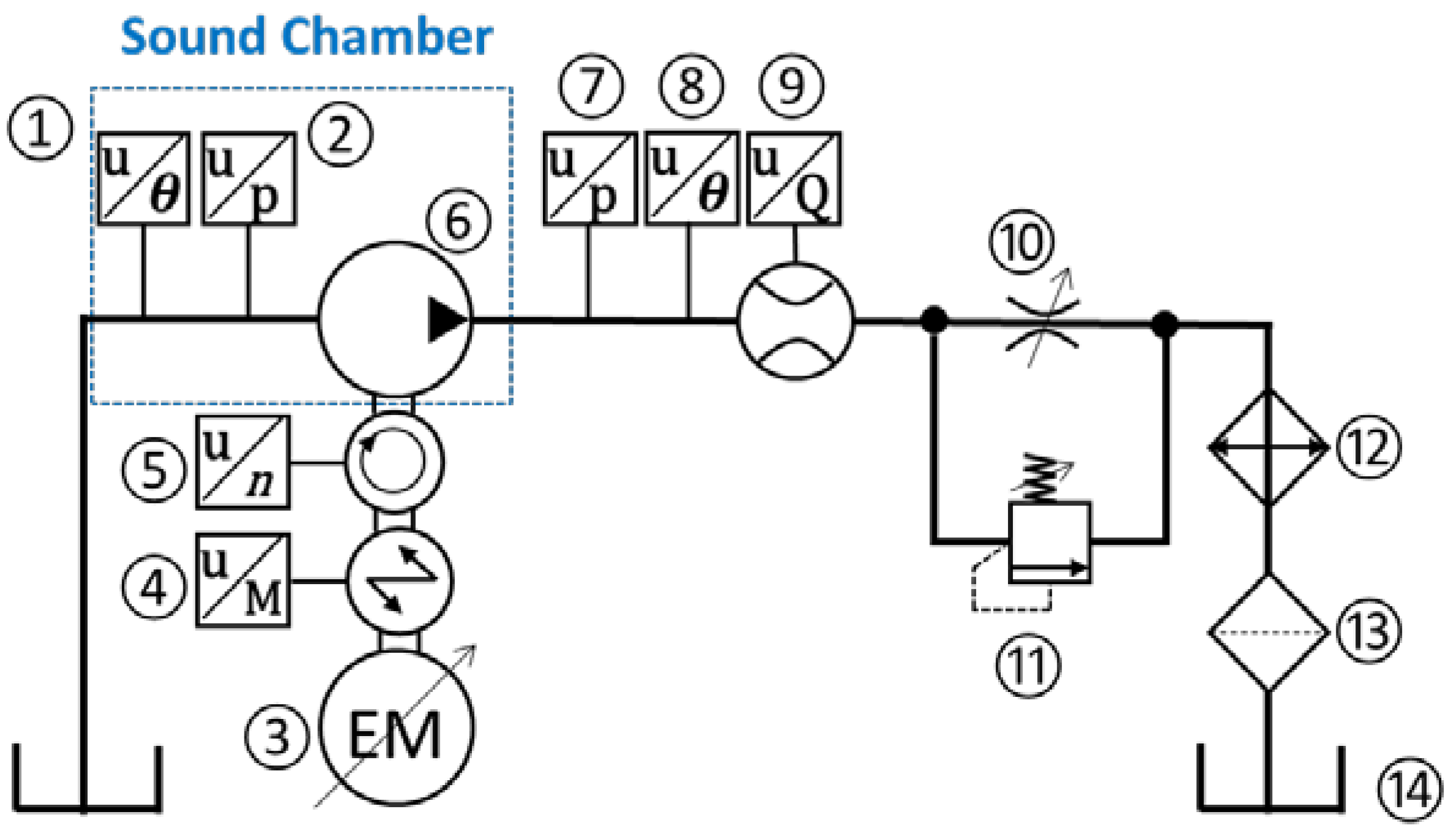
Figure 1. Hydraulic schematic for noise and vibration test.
Energies 13 06639 g001
Figure 2. Exploded view and specification of the reference pump.
Energies 13 06639 g002
Figure 3. (a) measurement points for structural (left) and air (right) domain and (b) corresponding measurement setups.
Energies 13 06639 g003
Figure 4. Acceleration signals measured at a single point at three different times (top) and their estimated power spectral densities (bottom).
Energies 13 06639 g004
Figure 5. (a) Conceptual diagram of working principle of an optical shaft encoder which generates the reference voltage signal, (b) simultaneously measured reference shaft encoder voltage signals (top) and acceleration signals (bottom) at three different times, and (c) zoomed-in plots for the phases of their estimated cross-spectral densities at harmonics of the pumping frequency.
Energies 13 06639 g005
Figure 6. Snapshots of Operational Deflection Shapes and radiated sound field taken over a cycle along with rms sound field at (a)1st, (b) 2nd, (c) 5th, and (d) 12th harmonics of the pumping frequency.
Energies 13 06639 g006aEnergies 13 06639 g006b
Figure 7. (a) The schematic of the experimental setup inside the sound chamber and (b) the equivalent simplified model to predict the acoustic pressure field radiated by the mounting plate with the absence of the pump.
Energies 13 06639 g007
Figure 8. Magnitude, phase, and snapshots over a cycle of vibration velocity normal to the mounting plate surface at (a) the first harmonic and (b) the second harmonic.
Energies 13 06639 g008
Figure 9. Comparisons of root-mean-squared sound pressures between the measurement and the results of Rayleigh integral using normal velocity of the only mounting plate at (a) first, (b) second, and (c) higher order harmonics. The snapshots of acoustic pressure over a cycle are given in (a) and (b).
Energies 13 06639 g009
Figure 10. Simple measurement of sound pressure level at the distance of 1 m from the pump.
Energies 13 06639 g010
Figure 11. (a) sound pressure levels measured at the center of sphere, (b) sound power levels of pump A (circles with solid lines) and pump B (diamonds with dashed lines) at different operating conditions, sound pressure level distribution of pump A (c) and pump B (d), and sound power spectrum of pump A (e) and pump B (f).
Energies 13 06639 g011
Figure 12. (a) Sound pressure level distributions, (b) overall sound power levels with different number of grid points, and (c) sound pressure distributions at different configurations of measurement positions that bring about the minimum, median and maximum sound power level for the three and six grid points.
Energies 13 06639 g012
Figure 13. A-weighted sound power spectrum (top) and sound pressure level field (bottom) at each repeated measurement.
Energies 13 06639 g013
Table 1. Details of hydraulic test rig components.
No.DescriptionDetails
1Inlet temperature sensorOmega Thermocouple Type K (Ni-Cr),
Temperature range: −200–850 °C, Accuracy: +1 °C
2Inlet pressure sensorHydac HDA 4185-B-0050-000-F1—Piezoresistive type
—Range: 0–3.4 bar, Accuracy: ±0.5%
3Variable electric motorSSB, Maximum operating torque: 500 Nm, Speed range: ±3000 rpm
4Torque meterHBM T30FNA
Torque range: ±500 Nm, Speed range: ±3000 rpm,
5Shaft speed sensorAccuracy: ±0.1%
6Test pumpExternal gear pumps
7Outlet pressure sensorHydac 4745—Strain gauge type—Range: 0–400bar,
Accuracy: ±0.25%
8Outlet temperature sensorOmega Thermocouple Type K (Ni-Cr),
Temperature range: −200–850 °C, Accuracy: +1 °C
9Outlet flow meterVSE VS4 GPO 12V—Fixed displacement volume (gear type)—Range: 1–250 L/min, Accuracy: ±0.3%
10Needle valveSun Hydraulics NFECKEN, Capacity: 30 gpm (113.6 L/min), Maximum operating pressure: 5000 psi (344.7 bar)
11Pressure relief valveSun Hydraulics RPICKCN, Capacity: 100 gpm (378.5 L/min), Maximum operating pressure: 5000 psi (344.7 bar)
12Heat exchangerParker OAW 46-60, Cooling Capacity: 23–142 hp (17.2–105.9 kW)
13FilterParker 50AT, Nominal Filter Rating: 10 micron, Nominal Flow Rating: 40 gpm (151.4 L/min)
14ReservoirBuyers UR 70S, Capacity: 70 gallon (265.0 L), ISO 46 oil
Table 2. Sound power level differences (reference: the level for 225 grid points), measurement time, and the grade of accuracy according to ISO 9614-1 depending on the different number of grid points.
Number of Grid Points (N)∆SWL
(dB/dBA)
Measurement Time (mins) Criterion :   N > C F 4 2 (ISO 9614-1)
Grade 1
(Precision)
Grade 2
(Engineering)
Grade 3
(Survey)
1−8.53/−7.970.1NoNoNo
3−0.56/−0.561NoNoNo
6+0.33/0.302NoNoNo
10−0.47/−0.482.5NoNoYes
20+0.03/0.004NoNoYes
36−0.25/−0.247NoYesYes
50−0.05/−0.0710NoYesYes
100−0.04/−0.0519.5YesYesYes
150−0.06/−0.0728YesYesYes
2250.00/0.0041.5YesYesYes
Table 3. Sound power level variations with the repetition (reference: the level for case 1).
Test 1Test 2Test 3
∆SWL (dBA)00.0040.012
Publisher’s Note: MDPI stays neutral with regard to jurisdictional claims in published maps and institutional affiliations.