Article

Reducing Rotor Temperature Rise in Concentrated Winding Motor by Using Magnetic Powder Mixed Resin Ring

1
Faculty of Engineering, Shinshu University, Matsumoto 380-8553, Japan
2
National Institute of Technology, Nagano College, Nagano 381-8550, Japan
*
Author to whom correspondence should be addressed.
Energies 2020, 13(24), 6721; https://doi.org/10.3390/en13246721
Submission received: 27 November 2020 / Revised: 14 December 2020 / Accepted: 17 December 2020 / Published: 20 December 2020
(This article belongs to the Special Issue Magnetic Material Modelling of Electrical Machines)

Abstract

:
The demand for high-speed servomotors is increasing, and minimal losses in both high-speed and high-torque regions are required. Copper loss reduction in permanent magnet motors can be achieved by configuring concentrated winding, but there are more spatial harmonics compared with distributed winding. At high-speed rotation, the eddy current loss of the rotor increases, and efficiency tends to decrease. Therefore, we propose a motor in which a composite ring made from resin material mixed with magnetic powder is mounted on the stator to suppress spatial harmonics. This paper describes three characteristic motor types, namely, open-slot motors, composite-ring motors, and closed-slot motors. Spatial harmonics are reduced significantly in composite-ring motors, and rotor eddy current loss is reduced by more than 50% compared with open-slot motors. Thermal analysis suggests that the saturation temperature rise value is reduced by more than 30 K. The use of a composite ring is effective in reducing magnet eddy current loss during high-speed rotation. Conversely, the torque characteristics in the closed-slot motor are greatly reduced as well as the efficiency. Magnetic circuits and simulations show that on electrical steel sheets with high relative permeability, the ring significantly reduces the torque flux passing through the stator, thus reducing the torque constant. To achieve reduced eddy current loss during high-speed rotation while ensuring torque characteristics with the composite ring, it is necessary to set the relative permeability and thickness of the composite ring according to motor specifications.

1. Introduction

Increasing motor efficiency is required to help prevent global warming [1,2], since more than 50% of the world’s total power consumption is caused by motor driving [3], more than 60% of which can be attributed to the industrial sector [4]. Electrification is progressing in automobiles and aircraft, and it is expected that the demand for increased motor efficiency will further increase [5,6,7]. Permanent magnet servomotors capable of accurate positioning and speed control are widely used in the industrial sector [8,9], and the demand for increased motor speed is increasing [10,11,12,13]. Therefore, the servomotor is required to reduce the losses associated with the high-speed rotation range and the high-torque range.
Permanent magnet motors have concentrated and distributed winding, and each winding method has its own advantages for improving efficiency. For concentrated winding, the winding resistance is reduced as well as the copper loss, since its coil end can be manufactured shorter than that of the distributed winding [14]. Furthermore, the eddy current loss of the rotor tends to increase at high-speed rotation in the concentrated winding because it has more spatial harmonics than distributed winding [15,16]. Slot combination optimization [17,18], skew [19,20,21], and closed slots [22,23] are effective in suppressing spatial harmonics. Skew tends to complicate the motor configuration, and the closed slot of the magnetic steel sheet may significantly reduce torque. Using bonded magnets makes it possible to reduce the eddy current loss of the rotor during high-speed rotation [24], but the torque constant tends to decrease compared with sintered rare-earth magnets [25]. A decrease in the torque constant significantly increases copper loss for a large torque. The magnet eddy current loss increases at high-speed rotation, and the temperature rise is high in the concentrated winding servomotor [26]. The bonded magnet motors and closed-slot motors made of electrical steel sheets can reduce magnet eddy current loss, but cannot maintain torque characteristics. For a concentrated winding high-speed servomotor, it is necessary to reduce the eddy current loss of the magnet while maintaining the torque constant.
This paper proposes a method using a resin material [27] mixed with magnetic powder as a method for reducing the spatial harmonics of a concentrated winding motor. The stator is made of magnetic resin in order to reduce the iron loss of the stator [28,29,30]. The magnetic composite is used for the teeth of the stator core. The advantages of composites have been reported to include their capability to form three-dimensional shapes and the fact that their core loss under high frequency conditions is relatively low [31]. In this paper, spatial harmonics are suppressed by constructing the ring from composite resin and attaching it to the stator. The magnetic composite resin has a relative permeability < 10–100, and it is effective in quelling the suppression of spatial harmonics while preventing the magnetic flux from short circuiting. In this paper, the effect of reducing both the eddy current loss of the rotor and the temperature rise value is clarified by simulation. Furthermore, the required thickness and relative permeability of the composite ring with respect to preventing the magnetic flux from short circuiting while maintaining torque characteristics are outlined with simulation results and magnetic circuit theory.

2. Magnetic Composite Ring Motor

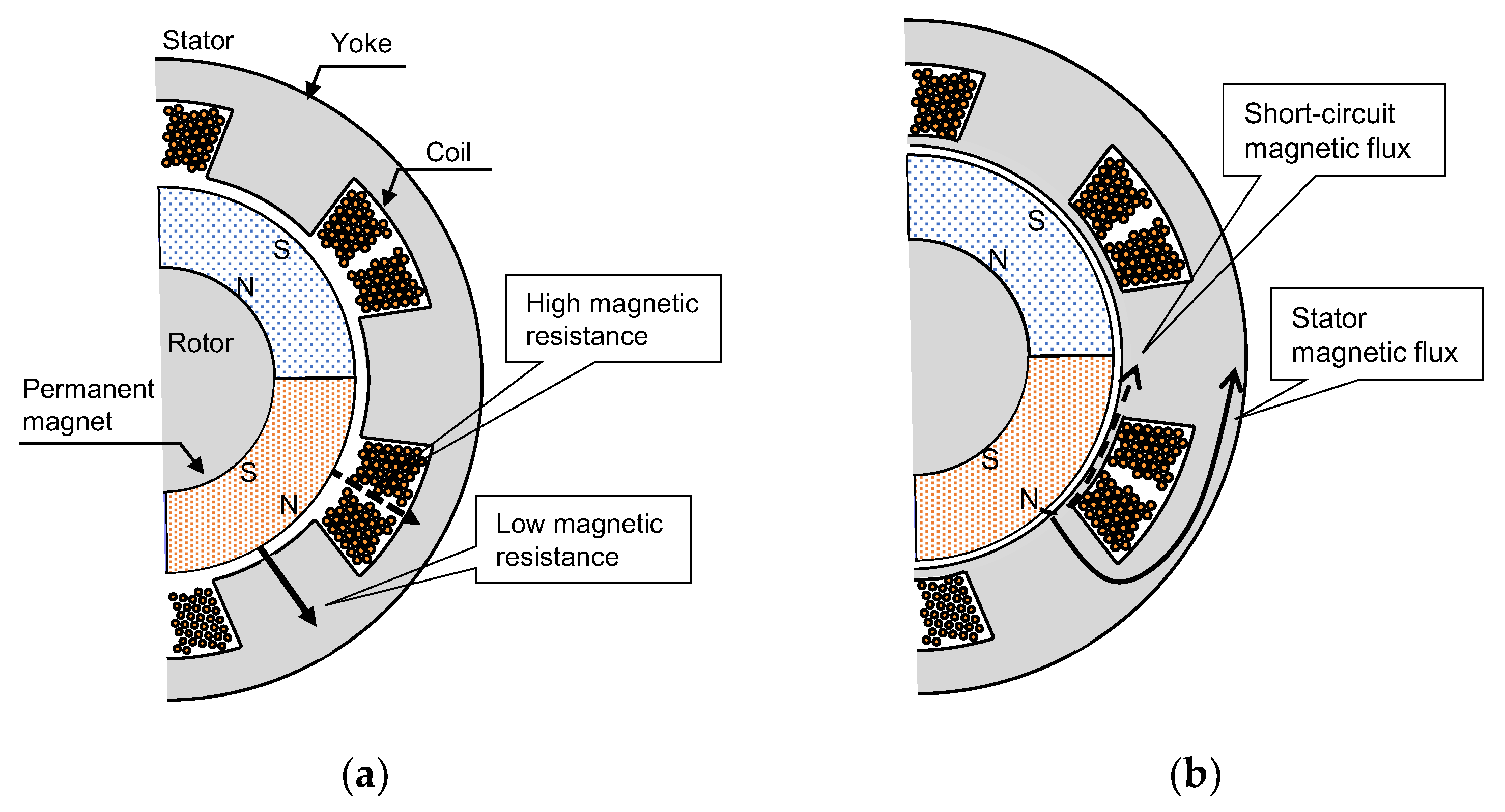
2.1. Magnet Eddy Current Loss

Figure 1a explains the cause of spatial harmonics in the cross-sectional configuration of the open-slot concentrated winding motor. The stator consists of a yoke and winding, and the rotor consists of a permanent magnet and yoke. The stator yoke is laminated with electromagnetic steel sheets punched into the same shape to reduce iron loss. In the direction of the solid arrow in Figure 1a, the magnetoresistance is relatively small due to the presence of the stator core. Conversely, the magnetic resistance to the direction of the dotted arrow in Figure 1a is relatively large due to the composition of copper and air. The magnetic resistance to the rotation angle of the rotor has a rectangular wave shape, and the fluctuation of the magnetic flux passing through the stator is large, so that the spatial harmonic becomes large. In particular, the distributed winding approaches a sinusoidal magnetic flux distribution, but the concentrated winding has a rectangular wave-shaped magnetic flux distribution, so spatial harmonics are likely to occur.
Rare-earth sintered magnets with a high-energy product are often used to increase the power density of motors. However, Nd rare-earth magnets, containing a large amount of iron, have high electrical conductivity, and fluctuating magnetic fields tend to cause eddy current loss [32,33]. In particular, the slot harmonics tend to increase the eddy current loss of the permanent magnet, since the concentrated winding motor has a large stator slot pitch. The carrier harmonics of the inverter also affect the eddy current loss of the magnet, but most of the components are caused by the slot harmonics [34]. The temperature rise of the magnet on the small motor tends to be high because the heat dissipation area of the magnet is sufficient. Eddy currents are proportional to the square of the frequency of the fluctuating magnetic field. The higher the rotation speed of the motor, the higher the demand for reducing the eddy current loss of the magnet. This is because the frequency for the change in magnetic flux applied to the iron core and magnet increases to a high level.
As shown in Figure 1b, the method of forming a closed slot with an electromagnetic steel plate is effective in suppressing spatial harmonics. Since the difference in magnetic resistance between the teeth portion and the coil portion is small when applying the said method, spatial harmonics are suppressed, and the effect of reducing eddy current loss is realized. However, the magnetic flux does not flow to the back yoke, as shown by the dotted arrow in Figure 1b, and the magnetic flux that short-circuits the closed-slot portion increases since the magnetic steel sheet has a high relative magnetic permeability. As shown by the solid arrow in Figure 1b, the torque constant decreases as the stator magnetic flux, which contributes to the generation of torque decreases. Copper loss increases because a current is required when a large torque is generated. Furthermore, when the magnetic flux flows through the closed slot, the magnetic flux density increased, which, in turn, increases iron loss.
Bonded magnets, in which magnets are kneaded into resin, are also effective in reducing magnet eddy current loss. However, they also reduce the gap magnetic flux density. Accordingly, the torque constant decreases, and copper loss tends to increase when a large torque is generated. This is unwanted, as a reduction in magnet eddy current loss is required without significantly reducing the torque constant.

2.2. Structure

Figure 2 shows the structure of a composite-ring motor (hereinafter referred to as a ring motor). Table 1 and Table 2 show the structural and material specifications of the ring motor, respectively.
The slot combination consists of four poles and six slots. The outer diameter of the stator is 32 mm, and the shaft length is 40 mm considering the miniaturization as servomotor applications. A ring is provided on the stator. The output of the motor is 500 W.
The difference between a ring motor and a closed-slot motor is that the ring is made of a magnetic composite material instead of electrical steel sheeting. The composite ring formed of a resin material mixed with magnetic powder was mounted on a stator, and windings were embedded with a magnetic material in the ring motor. The magnetic composite material was manufactured by mixing magnetic powder and resin [35,36]. Magnetic composite materials have a higher relative permeability than air, and their relative permeability is significantly smaller than that of electrical steel sheets. Accordingly, the difference in magnetic resistance between the teeth and coil section is reduced, and spatial harmonics can be reduced without suppressing the short circuiting of the magnetic flux. In addition, the magnetic composite material has a high electrical resistance due to the resin. Therefore, it contributes to the reduction in eddy current loss compared to the construction of electrical steel sheets.

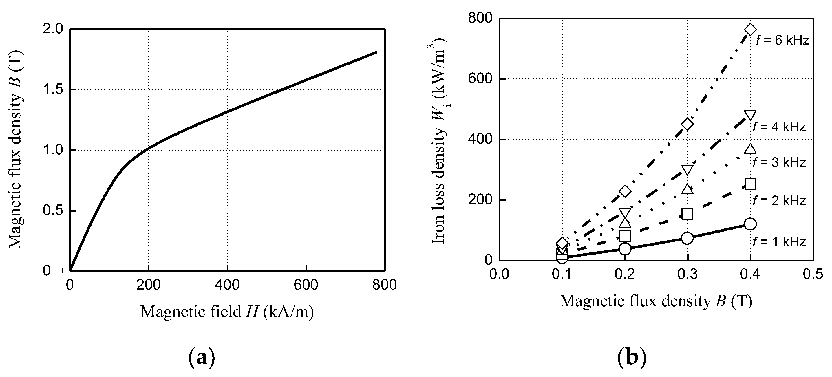
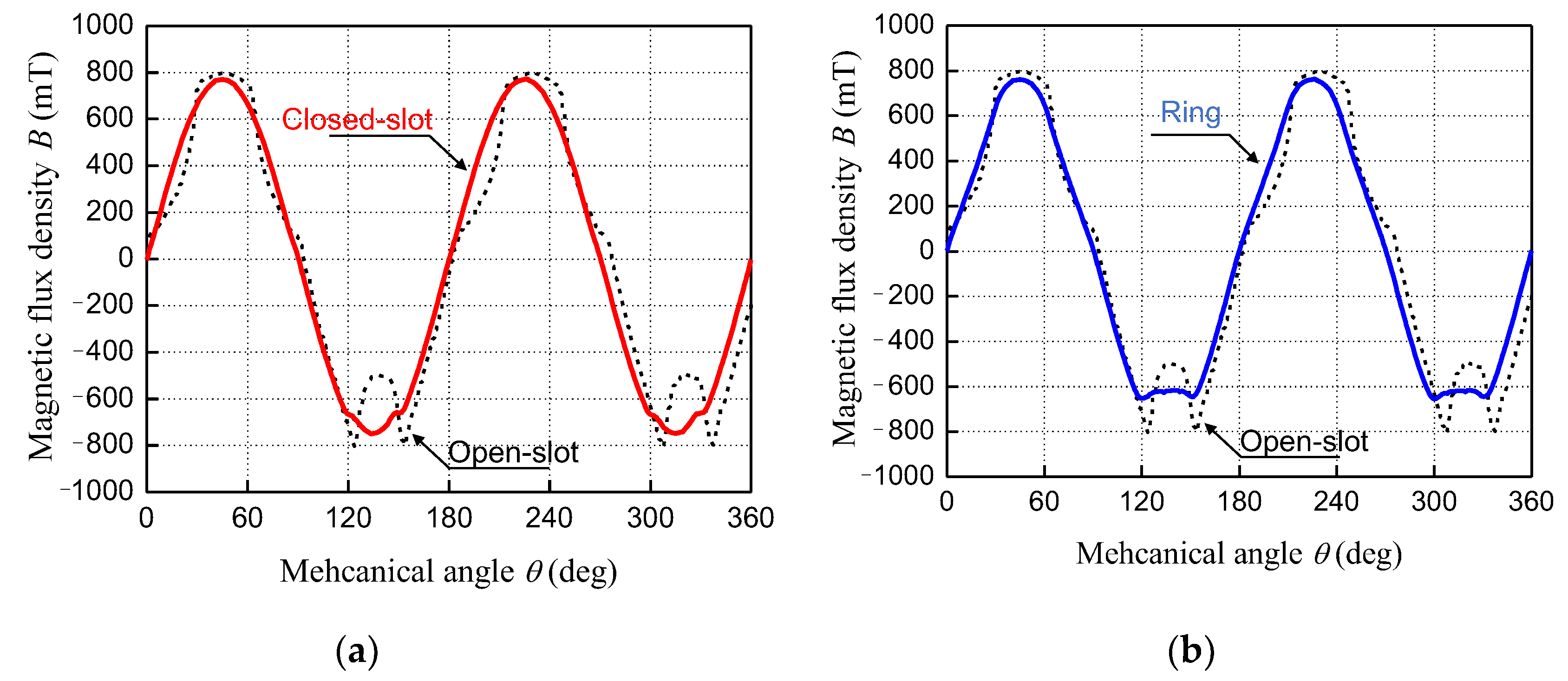
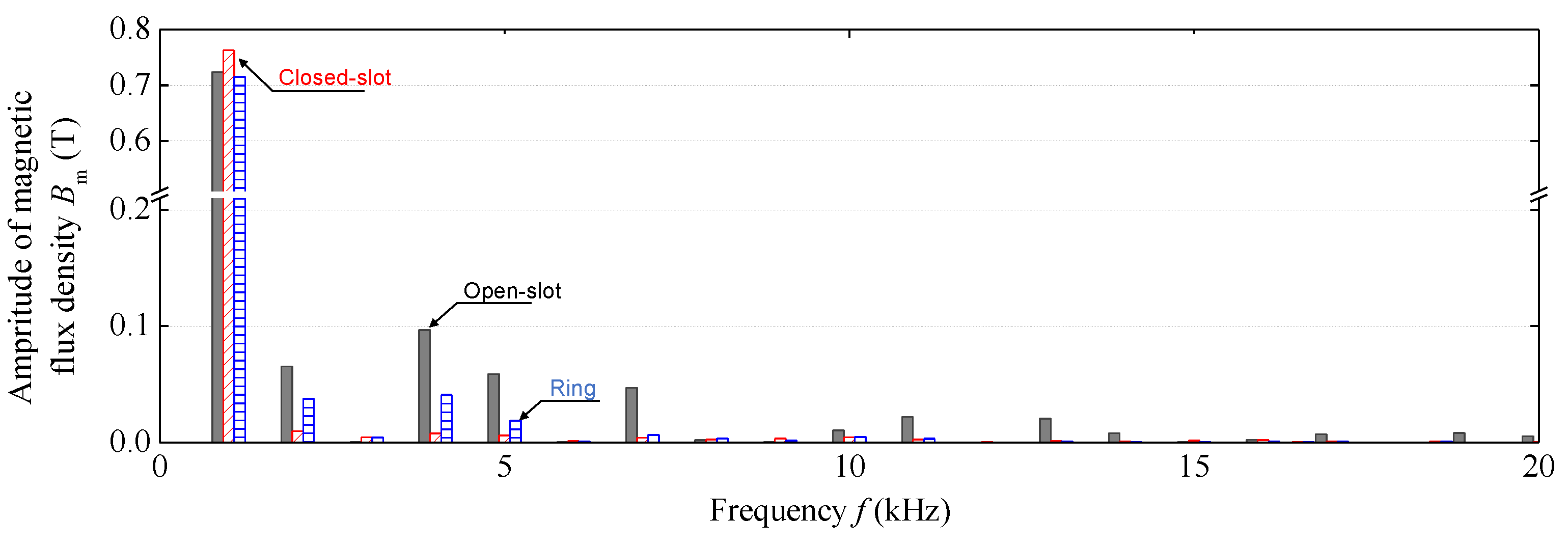
2.3. Magntic Ring Characteristics

The magnetic composite material was manufactured by mixing, stirring, and firing iron amorphous ball powder with an average particle size of 2.6 µm and the impregnated adhesive V-2000 at a volume ratio of 64 vol.% [36]. The magnetic properties were evaluated with a toroidal core made of a magnetic composite material. Figure 3a,b show the measurement results of the magnetization characteristics using a vibrating sample magnetometer (BHV-55: RIKEN-DENSHI) and iron loss characteristics using a B-H analyzer (SY-8218: IWATSU ELECTRIC), respectively. The real part (µ’) of the complex specific magnetic coefficient is 10.4, which is slightly larger than that of air and significantly lower than that of electrical steel sheets. These measurement results will be used for simulations in Chapter 3.

3. Effect on Reducing Rotor Temperature Rise

This section clarifies the reducing temperature rise effect of the magnetic ring using simulations. The effect of the magnetic ring motor is confirmed based on the loss of the magnetic field analysis and the temperature rise value of the thermal analysis.

3.1. Simulation Conditions

Table 3 shows the analysis conditions. By comparing the ring motor with three types of open-slot motors without magnetic rings and three types of closed-slot motors with electrical steel sheets, the spatial harmonics and loss suppression effect of the ring motor were confirmed based on the magnetic field analysis. The magnetic field was analyzed using the two-dimensional finite element method (FEM) with JMAG-Designer [37]. The external dimensions of all motors are the same at 32 mm. The gap length was set to 0.7 mm considering winding a synthetic twisted yarn to prevent the magnet from scattering during high-speed rotation. The 0.7 mm gap of the open-slot motor was secured by changing the length of the teeth without changing the outer shape. The armature current was adjusted to ensure the motor output was maintained at 500 W.
Thermal analysis was based on the finite element method and the heat conduction equation of JMAG-Designer. Table 4 summarizes the thermal characteristic parameters. The temperature rise was calculated based on the loss of each part derived by magnetic field analysis. Figure 4 shows the thermal circuit assumed in the simulation. The stator consists of a core and coil, and the rotor consists of a core, a magnet, and a shaft. The coil and magnet are the main heat sources. Heat is transferred by contact thermal resistance and dissipated from the rotor surface, the stator core, and the coil into the air by heat transfer. By calculating the temperature rise of each part, the effectiveness of the ring motor in reducing the temperature rise can be clarified.

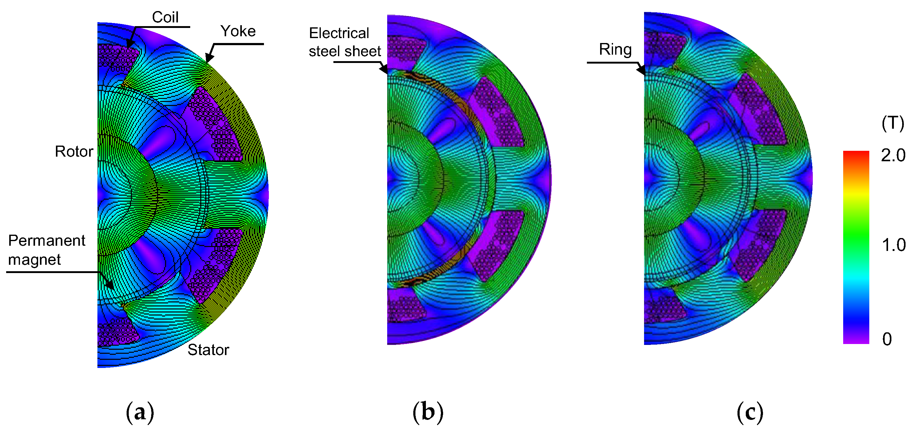
3.2. Loss Analysis Results

Figure 5 shows the magnetic flux density distribution calculated by simulation. In open-slot motors, most of the magnetic flux passes through the teeth of the stator, but in closed-slot motors, the short circuit of the magnetic flux for the ring is quite large. Conversely, the short circuit of the ring is small for the ring motor. Figure 6 shows the angle dependence of the magnetic flux density in the gap. The open-slot motor is close to a square wave, whereas the closed-slot motor is almost sinusoidal. The ring motor is also in a state approximal to a sine wave. Figure 7 shows the Fourier transform result for the magnetic flux density, from which it is evident that harmonic components are significantly suppressed and the fundamental wave component is increased in closed-slot motors, which is consistent with the tendency in Figure 6a. Moreover, for the ring motors, the fourth, fifth and seventh harmonic components decrease by 50% or more. Accordingly, suppression of spatial harmonics can be realized using a ring.
Figure 8 shows the current density distribution. The magnet of an open-slot motor has a large area of high current density. However, the area of high current density is small in the magnet part of magnetic ring motors and closed-slot motors. The generation of eddy currents in the magnet can be reduced with a ring motor because the spatial harmonics are suppressed, as mentioned in the previous section.
Figure 9 shows the torque characteristics of each motor. Indeed, the decrease in the torque constant of the closed-slot motor is remarkable. In particular, the closed-slot motors have a torque constant that is 18% smaller than that of open-slot motors. Although the torque characteristics are reduced by providing the ring, the torque constant is reduced by 8% in the ring motor compared with the closed-slot motor. The short circuit of the magnetic flux of the magnet was suppressed, and the reduction in the effective magnetic flux that contributes to the torque was avoided by applying a composite material with low relative permeability to the ring as shown in Figure 3.
Table 5 shows the results of comparing the losses of each motor. The open-slot motor has a large magnet eddy current loss. The closed-slot motor can reduce the eddy current loss of the magnet, but the copper loss increases significantly as the torque constant decreases for an output power of 500 W. Although the torque constant of the magnetic ring motor is slightly reduced, the expected effect of the magnet eddy current loss is reduced by 78%. The ring motor had the highest efficiency compared with other motors operating at the same output of 500 W. A bond magnet motor with the same dimensions as the open-slot motor was also simulated for comparison to continue torque characteristics and losses. A bond magnet (Hidence-1000) was used as the permanent magnet of the open-slot motor. The magnet eddy current loss of the bond magnet motor was reduced. However, the torque constant is considerably lower than that of the magnetic ring motor, and the total loss is also large. Accordingly, the magnetic ring can reduce the magnet eddy current loss without significantly reducing the torque constant.
Figure 10 shows the dependence of the efficiency on the output in each motor. Magnetic ring motors maintain higher efficiency than open-slot motors from low- to high-power regions. Since the closed-slot motor have a low torque constant, copper loss increases at high output. Conversely, since the torque constant of the ring motor is higher than that of the closed-slot motor, the efficiency is the highest due to the effect of suppressing copper loss and reducing the eddy current loss of the magnet at high output. The ring motor achieves high efficiency in the high speed and torque range.

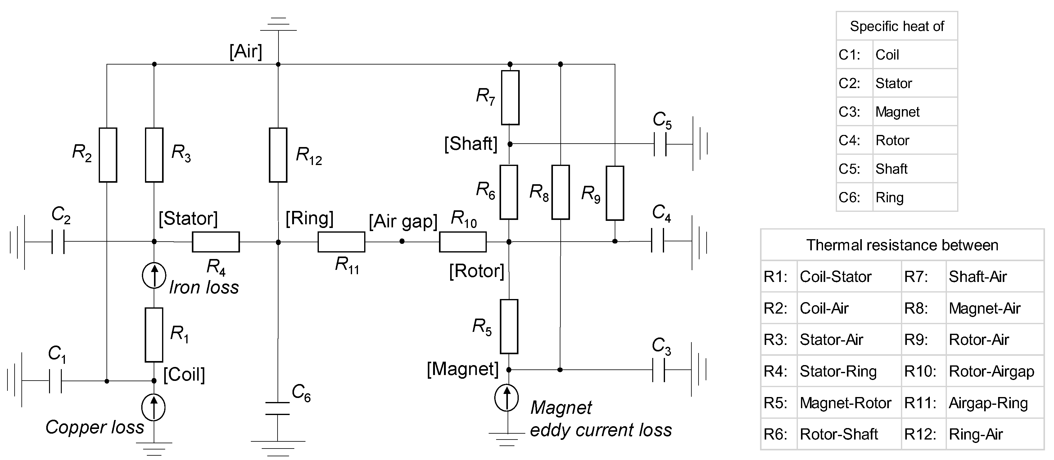
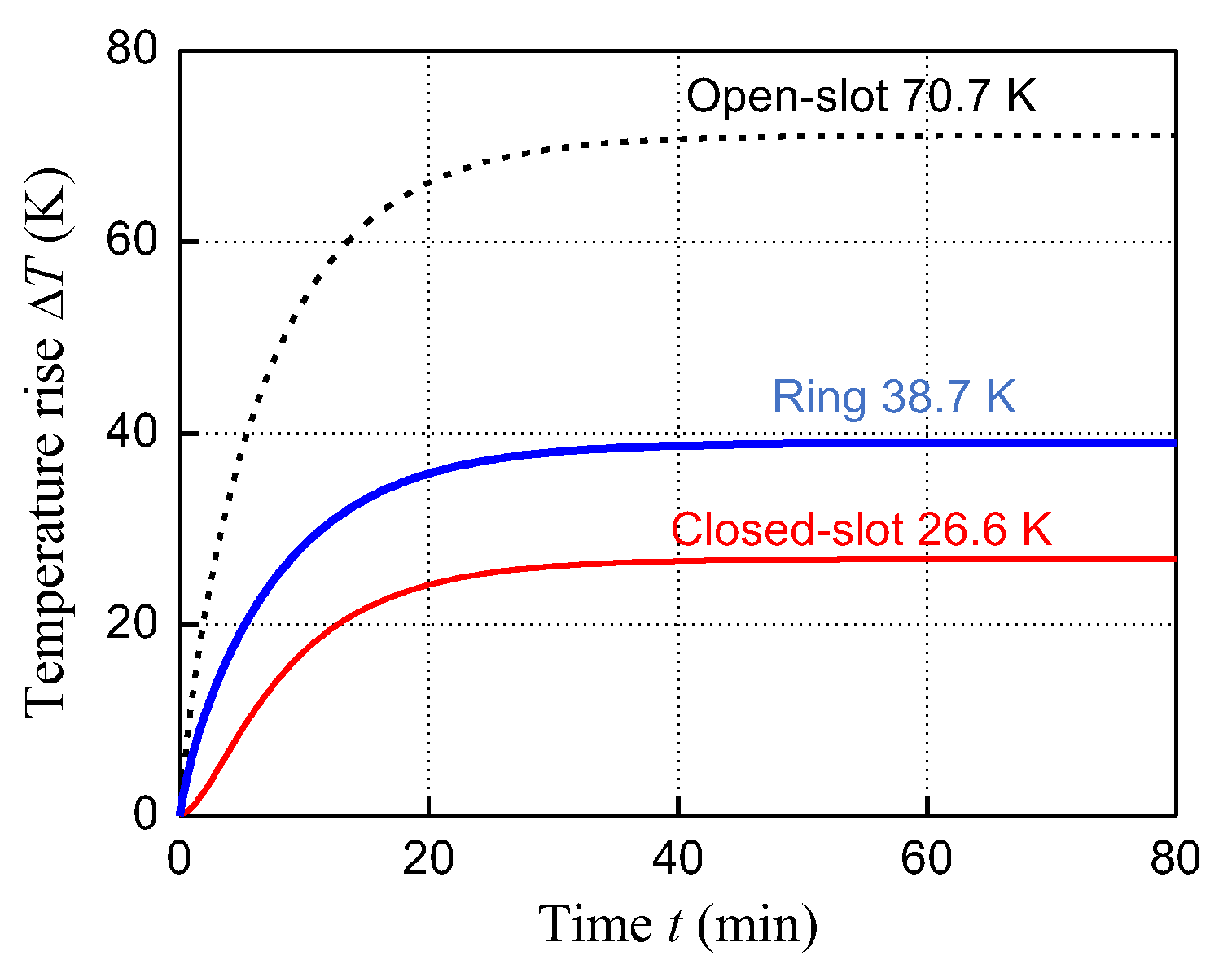
3.3. Temperature Rise Analysis Results

Mounting a ring is effective in reducing the eddy current loss of the magnet. Therefore, the effect of reducing the rotor temperature due to the magnetic ring has been confirmed by thermal analysis simulation. Figure 11 shows the time transition of the temperature rise of each part. Overall, the saturation temperature rise of magnets for closed-slot motors and ring motors is reduced by over 30 K. Particularly, the saturation temperature rise at 30,000 rpm with 500 W is lower than 40 K for the open-slot and the ring motor. The temperature rise of the magnet of the closed-slot motor reduced to the same value as that of the ring motor. Accordingly, a magnetic composite ring is effective in reducing the temperature rise of permanent magnets. Ring motors can be also expected to suppress thermal demagnetization and magnet breakage.

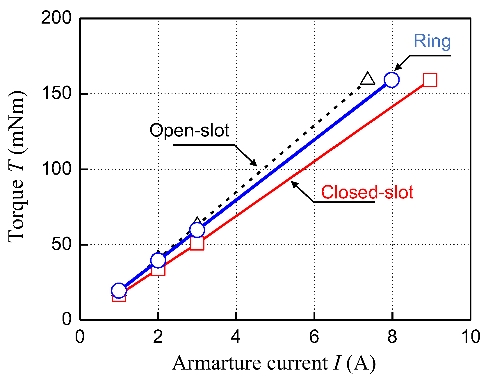
4. Torque Characteristics

In Section 3, the magnetic ring was shown to be effective in suppressing spatial harmonics. Alternatively, for the closed-slot motor, the magnetic flux of the magnet often short-circuited, and the torque constant was significantly reduced. A short circuit of the magnetic flux occurs on the stator side, and the torque constant decreases due to the characteristics of the magnetic ring. Therefore, this section focuses on the thickness and relative permeability of the magnetic ring, which are influencing factors over the short circuiting of the magnetic flux. Simulation results and magnetic circuit theory are used to explain the effect of changing the ring thickness and relative permeability on the torque characteristics.

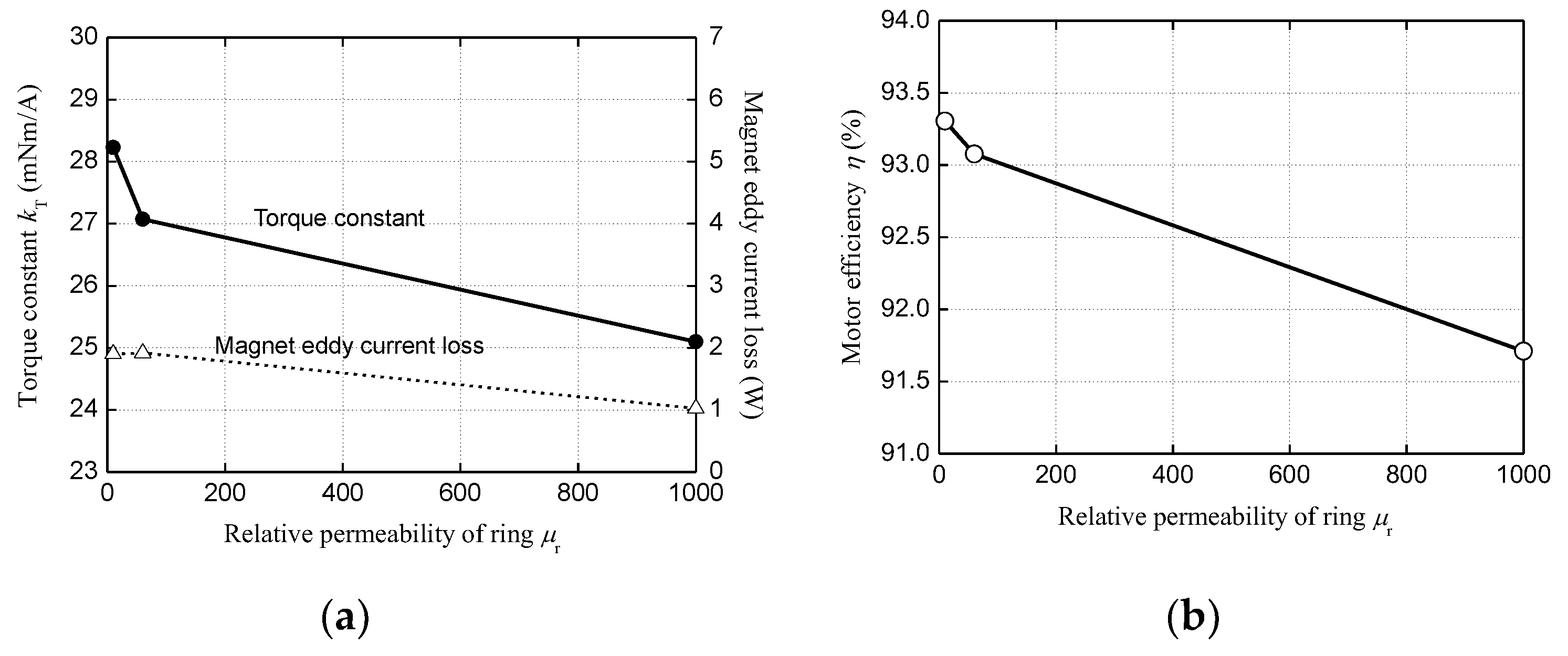
4.1. Torque Characteristics

The relative permeability and thickness of the ring affect the short-circuit state of the permanent magnet magnetic flux on the stator side, by which the torque constant changes. Therefore, the torque characteristics when the thickness of the magnetic ring and the relative permeability are changed were derived by magnetic field simulation.
The thickness of the magnetic ring was changed to 0.5, 0.6, 0.7, 0.9, and 1.1 mm to confirm the effect of short circuiting the permanent magnet flux on the stator side. The outer diameter of each motor was 32 mm, the air gap was 0.7 mm, and the thickness of the magnet changed according to changes in the magnetic ring thickness. The relative permeability of the ring was constant at 10. All motor outputs were 500 W, and the simulation conditions are the same as those in Section 3. Figure 12a,b show the dependency on ring thickness of the torque constant, eddy current loss of the magnet, and motor efficiency based on the simulation. As the thickness of the magnetic ring increases, the torque constant decreases proportionally. Conversely, the eddy current loss of the magnet increases as the ring thickness increases. Maximum efficiency is achieved with a ring thickness of 0.7 mm, which can be attributed to the trade-off between copper loss and eddy current loss in the magnets. The copper loss of the coil increases because the current required for the same output increases as the torque constant decreases.
The torque characteristics were compared by changing the relative magnetic permeability to 10, 60, and 1000 with a ring thickness of 0.7 mm. Figure 13a,b show the dependency on ring relative permeability of the torque constant, eddy current loss of the magnet, and motor efficiency based on the simulation. Rings with a relative permeability of 10 are used in the transformer cores of DC-DC converters [38]. A permeability of 60 and 1000 was assumed for the dust core manufactured by Dongbu Electronic Materials Co., Ltd. and for the electrical steel sheet, respectively. The torque constant decreases in inverse proportion; conversely, the magnet eddy current loss reduced with an increase in the relative magnetic permeability. The efficiencies for the relative permeabilities of 10 and 60 are almost the same, but the effect of lowering the torque constant is greater than that of reducing the eddy current loss at a relative permeability of 1000. Accordingly, to obtain the same output of 500 W, the copper loss increases to a large value and the efficiency decreases.

4.2. Magnteic Circuit

The simulation results in Section 4.1 are analyzed by comparing them with the magnetic circuit of the motor. Figure 14 shows a magnetic circuit of a magnetic ring motor. Rm, Ra, Rr, and Rs denote the reluctance of the magnet, the air gap, the ring, and the stator core, respectively. Although the cross-sectional area through which magnetic flux passes differs between the teeth and yoke of the stator core, the magnetic resistance is smaller than that of the ring. Therefore, the reluctance of the teeth and yoke of the stator core can be calculated together for simplification. The magnetic resistance of each part is given by Equation (1).
R = l μ μ 0 d w
where µ denotes the relative permeability, l denotes the magnetic path length, w denotes the axial length, and d denotes the magnetic path cross-sectional length.
The relationship between the short-circuit magnetic flux of the ring (ϕr), the stator magnetic flux that contributes to torque (ϕs), and the magnet magnetic flux (ϕm) is given by Equation (2). The magnetomotive force (Fm) of a magnet is represented by the product of the coercive force (Hm) of the magnet and the thickness of the magnet (tm) as described in Equation (3). The magnet thickness tm changes in proportion to ring thickness (tr), as described by Equation (4), assuming that the motor external dimensions and air gap distance are constant in this study. Therefore, magnet magnetic flux changes in proportion to the thickness of the magnetic ring, as described by Equation (5) with total reluctance (Rt). Equation (6) expresses the relationship between the magnet magnetic flux and the stator magnetic flux in the shunt rule of the magnetic circuit with reluctances Rs and Rr.
The stator magnetic flux is represented by the product of the term related to the shunt flow of the ring and the term related to the magnet magnetic flux. The term of the magnet magnetic flux directly decreases more than the term related to the ring shunt flow with same the relative magnetic permeability of the ring. Therefore, the torque magnetic flux decreases in proportion to magnet thickness.
When the magnet thickness is increased with the same relative magnetic permeability of the ring, the influence of the magnetomotive force term is larger than that related to the shunt flow. Therefore, the stator magnetic flux ϕs decreases, and the torque constant proportionally decreases, which is the same relationship shown in Figure 12a. Conversely, when the relative permeability is increased while maintaining the same magnetic ring thickness, only the shunt term of the ring decreases in an inverse proportion. Therefore, the stator magnetic flux decreases, and the torque constant decreases in an inverse proportion, which is the same relationship shown in Figure 13a.
ϕ m = ϕ r + ϕ s
F m = H m t m
t m = D o 2 D f 2 t g t s t r
ϕ m = F m R t t r
ϕ s = R r R s + R r × ϕ m = l r μ r μ 0 t r w m l s μ s μ 0 d s w m + l r μ r μ 0 t r w m × ϕ m = μ s d s l r μ r t r l s + μ s d s l r × ϕ m
where ϕr: the short-circuit magnetic flux of the ring, ϕs: the stator magnetic flux that contributes to torque, ϕm: the magnet magnetic flux, Fm: magnetomotive force of a magnet, Hm: coercive force, tm: thickness of the magnet, Do: stator outer diameter, Df: shaft outer diameter, tg: air gap length, ts: thickness of electrical steel sheet, tr: thickness of ring, Rt: synthetic reluctance, ls: magnetic flux length through the stator, ds: width of stator teeth, wm: axial length of the motor, lr: magnetic flux length through the ring, μr: relative permeability of ring, and μs: relative permeability of stator.
The magnetic resistance of the ring decreases by larger the relative permeability or thickness of the ring, which increases the short-circuiting of the magnetic flux. This means that the stator magnetic flux decreases in proportion to the torque constant kt. Therefore, setting an appropriate magnetic ring thickness and relative magnetic permeability based on the motor specifications, such as the magnetomotive force and stator size, is important with respect to improving motor efficiency by using the magnetic ring.

5. Conclusions

A concentrated winding motor that tends to generate spatial harmonics has a high magnet eddy current loss at high-speed rotation. This paper proposes a method of attaching a resin ring mixed with magnetic powder to the stator to suppress spatial harmonics. We have clarified the following points by simulation.
(1)
The fourth, fifth, and seventh harmonic components were reduced by over 50% using a 0.7 mm-thick composite ring.
(2)
The magnet eddy current loss for the ring motor was reduced by 78%, and the temperature rise value was reduced by 30 K compared with the open-slot motor.
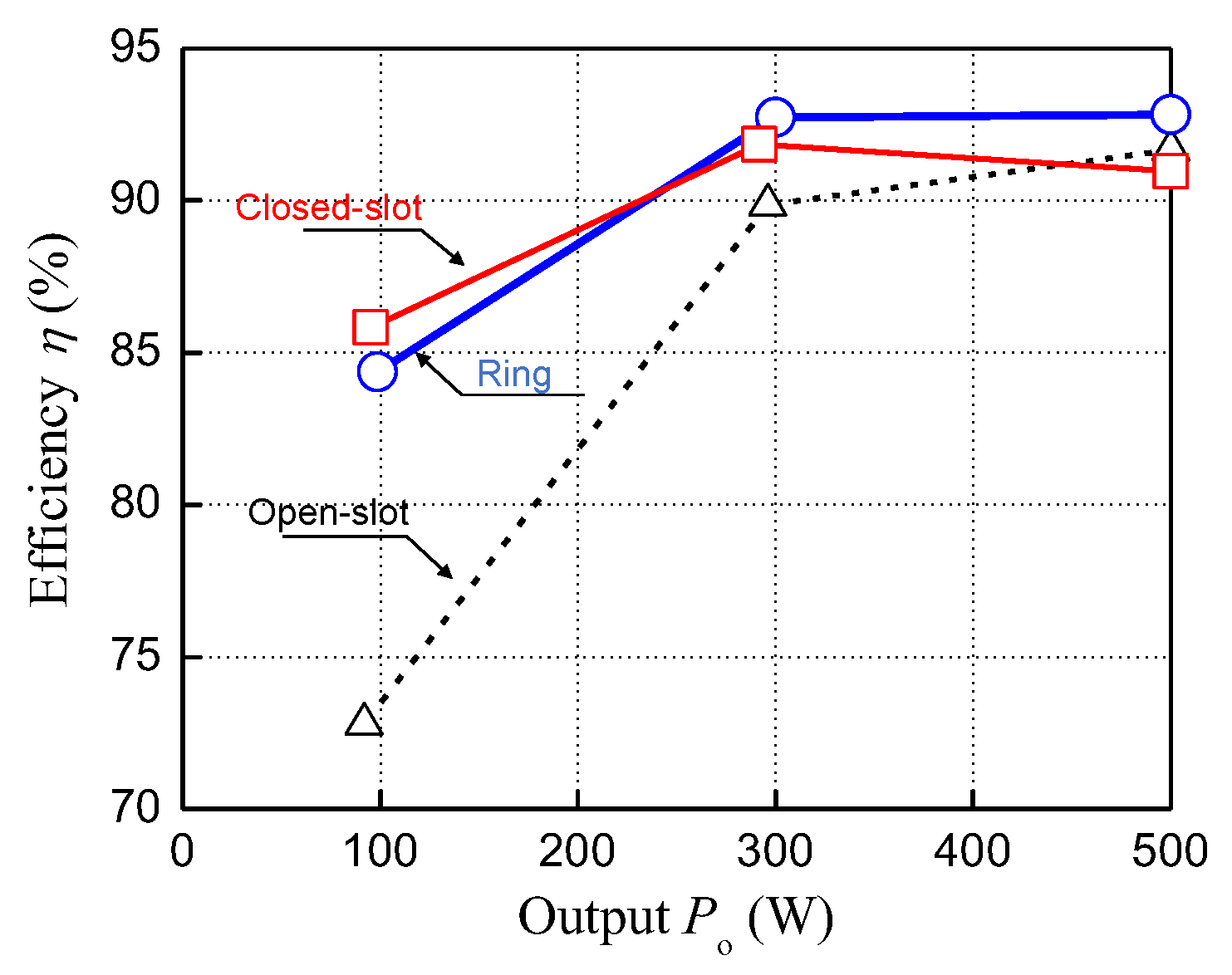
(3)
The efficiency of the ring motor was improved by 1.1% and 1.8% compared with the open-slot and closed-slot motor made of electrical steel sheeting, respectively.
The closed-slot motor was the most effective in suppressing spatial harmonics, but the torque constant was significantly reduced due to the high relative magnetic permeability of the electromagnetic steel sheets forming the ring. Therefore, the effects of ring thickness and relative magnetic permeability on torque characteristics were confirmed by simulations and magnetic circuits.
Increasing the magnetic flux of the magnet passing through the ring reduced the torque constant of the motor. Setting both the appropriate composite ring thickness and relative permeability is essential with respect to suppressing spatial harmonics without compromising torque characteristics.

Author Contributions

Conceptualization and methodology, M.S., M.N., T.M. and Y.B.; software, K.T., M.H., R.Y. and R.M.; validation, K.T., R.Y. and R.M.; writing—original draft preparation, M.S. and K.T.; funding acquisition, M.S. and T.M. All authors have read and agreed to the published version of the manuscript.

Funding

This research is supported by Adaptable and Seamless Technology transfer Program through Target-driven R&D (A-STEP) from Japan Science and Technology Agency (JST).

Conflicts of Interest

The authors declare no conflict of interest.

References

  1. Lee, J.; Jung, D.; Lim, J.; Lee, K.; Lee, J. A study on the synchronous reluctance motor design for high torque by using RSM. IEEE Trans. Magn. 2018, 54, 1–5. [Google Scholar] [CrossRef]
  2. Liu, C.; Shih, P.; Cai, Z.; Yen, S.; Lin, H.; Hsu, Y.; Luo, T.; Lin, S. rotor conductor arrangement designs of high-efficiency direct-on-line synchronous reluctance motors for metal industry applications. IEEE Trans. Ind. Appl. 2020, 56, 4337–4344. [Google Scholar]
  3. Tabora, J.M.; de Lima Tostes, M.E.; de Matos, E.O.; Soares, T.M.; Bezerra, U.H. Voltage harmonic impacts on electric motors: A comparison between IE2, IE3 and IE4 induction motor classes. Energies 2020, 13, 3333. [Google Scholar] [CrossRef]
  4. Gómez, J.R.; Quispe, E.C.; Castrillón, R.P.; Viego, P.R. Identification of technoeconomic opportunities with the use of premium efficiency motors as alternative for developing countries. Energies 2020, 13, 5411. [Google Scholar] [CrossRef]
  5. Son, J.-C.; Kang, Y.-R.; Lim, D.-K. Optimal design of IPMSM for FCEV using novel immune algorithm combined with steepest descent method. Energies 2020, 13, 3395. [Google Scholar] [CrossRef]
  6. Cui, S.; Zhao, T.; Du, B.; Cheng, Y. Multiphase PMSM with asymmetric windings for electric Drive. Energies 2020, 13, 3765. [Google Scholar] [CrossRef]
  7. de Pinto, S.; Camocardi, P.; Chatzikomis, C.; Sorniotti, A.; Bottiglione, F.; Mantriota, G.; Perlo, P. On the comparison of 2- and 4-wheel-drive electric vehicle layouts with central motors and single- and 2-speed transmission systems. Energies 2020, 13, 3328. [Google Scholar] [CrossRef]
  8. Flieh, H.M.; Slininger, T.; Lorenz, R.D.; Totoki, E. Self-sensing via flux injection with rapid servo dynamics including a smooth transition to back-EMF tracking self-sensing. IEEE Trans. Ind. Appl. 2020, 56, 2673–2684. [Google Scholar] [CrossRef]
  9. Mese, E.; Yasa, Y.; Ertugrul, B.; Sincar, E. Design of a high performance servo motor for low speed high torque application. In Proceedings of the 2014 International Conference on Electrical Machines (ICEM), Berlin, Germany, 2–5 September 2014; pp. 2014–2020. [Google Scholar] [CrossRef]
  10. Ogata, T.; Maruyama, H.; Fujita, K. A spindle motor servo using a disturbance observer. In Proceedings of the 2009 Digest of Technical Papers International Conference on Consumer Electronics, Las Vegas, NV, USA, 10–14 January 2009; pp. 1–2. [Google Scholar] [CrossRef]
  11. Liu, N.-W.; Hung, K.-Y.; Yang, S.-C.; Lee, F.-C.; Liu, C.-J. Design of high-speed permanent magnet motor considering rotor radial force and motor losses. Energies 2020, 13, 5872. [Google Scholar] [CrossRef]
  12. Kim, S.; Kim, Y.; Lee, G.; Hong, J. A novel rotor configuration and experimental verification of interior PM synchronous motor for high-speed applications. IEEE Trans. Magn. 2012, 48, 843–846. [Google Scholar] [CrossRef]
  13. Wang, X.; Luo, J.; Du, M. Rotor strength analysis of high-speed motor based on magnetic pole eccentricity. AIP Conf. Proc. 2019, 2154, 020008. [Google Scholar] [CrossRef]
  14. Frosini, L.; Pastura, M. Analysis and design of innovative magnetic wedges for high efficiency permanent magnet synchronous machines. Energies 2020, 13, 255. [Google Scholar] [CrossRef] [Green Version]
  15. Atallah, K.; Howe, D.; Mellor, P.H.; Stone, D.A. Rotor loss in permanent magnet brushless AC machine. IEEE Trans. Ind. Appl. 2000, 36, 1612–1618. [Google Scholar]
  16. Jung, J.-W.; Lee, B.-H.; Kim, K.-S.; Kim, S.-I. Interior permanent magnet synchronous motor design for eddy current loss reduction in permanent magnets to prevent irreversible demagnetization. Energies 2020, 13, 5082. [Google Scholar] [CrossRef]
  17. Zhu, Z.Q.; Howe, D. Influence of design parameters on cogging torque in permanent magnet machines. IEEE Trans. Energy Convers. 2000, 15, 407–412. [Google Scholar] [CrossRef] [Green Version]
  18. Kaimori, H.; Akatsu, K. Behavior Modeling of permanent magnet synchronous motors using flux linkages for coupling with circuit simulation. IEEJ J. Ind. Appl. 2018, 7, 56–63. [Google Scholar] [CrossRef] [Green Version]
  19. Li, Q.; Zhang, B.; Liu, A. Cogging torque computation and optimization in dual-stator axial flux permanent magnet machines. IEEJ Trans. Electr. Electron. Eng. 2020, 15, 1414–1422. [Google Scholar] [CrossRef]
  20. Jo, I.; Lee, H.; Jeong, G.; Ji, W.; Park, C. A study on the reduction of cogging torque for the skew of a magnetic geared synchronous motor. IEEE Trans. Magn. 2019, 55, 1–5. [Google Scholar] [CrossRef]
  21. Mitsui, Y.; Ahmed, S.; Aoyama, Y.; Koseki, T. Detent force reduction by positional shifting of permanent magnets for a PMLSM without compromising thrust. IEEJ J. Ind. Appl. 2020, 9, 376–383. [Google Scholar]
  22. Tang, H.; Zhang, M.; Dong, Y.; Li, W.; Li, L. Influence of the opening width of stator semi-closed slot and the dimension of the closed slot on the magnetic field distribution and temperature field of the permanent magnet synchronous motor. IET Electr. Power Appl. 2020, 14, 1642–1652. [Google Scholar] [CrossRef]
  23. Chun, J.-S.; Jung, H.-K.; Yoon, J.-S. Shape optimization of closed slot type permanent magnet motors for cogging torque reduction using evolution strategy. IEEE Trans. Magn. 1997, 33, 1912–1915. [Google Scholar] [CrossRef]
  24. Tsunata, R.; Takemoto, M.; Ogasawara, S.; Watanabe, A.; Ueno, T.; Yamada, K. Development and evaluation of an axial gap motor using neodymium bonded magnet. IEEE Trans. Ind. Appl. 2018, 54, 254–262. [Google Scholar] [CrossRef]
  25. Hosoya, R.; Shimomura, S. Apply to in-wheel machine of permanent magnet vernier machine using NdFeB bonded magnet—Fundamental study. In Proceedings of the 8th International Conference on Power Electronics—ECCE Asia, Jeju, Korea, 30 May–3 June 2011; pp. 2208–2215. [Google Scholar] [CrossRef]
  26. Shi, W.; Zhou, X. Online estimation method for permanent magnet temperature of high-density permanent magnet synchronous motor. IEEJ Trans. Electr. Electron. Eng. 2020, 15, 751–756. [Google Scholar] [CrossRef]
  27. Sato, M.; Sugimoto, K.; Kubota, K.; Endo, S.; Mizuno, T. Reducing the alternating current resistance and heat generation in a single-wire coil using a magnetic tape. IEEJ Trans. Electr. Electron. Eng. 2020, 15, 1541–1548. [Google Scholar] [CrossRef]
  28. Guo, Y.; Zhu, J.; Lu, H.; Lin, Z.; Li, Y. Core loss calculation for soft magnetic composite electrical machines. IEEE Trans. Magn. 2012, 48, 3112–3115. [Google Scholar] [CrossRef]
  29. Guo, Y.; Zhu, J.G.; Watterson, P.A.; Wu, W. Development of a PM transverse flux motor with soft magnetic composite core. IEEE Trans. Energy Convers. 2006, 21, 426–434. [Google Scholar] [CrossRef]
  30. Guo, Y.; Zhu, J.; Dorrell, D.G. Design and analysis of a claw pole permanent magnet motor with molded soft magnetic composite core. IEEE Trans. Magn. 2009, 45, 4582–4585. [Google Scholar]
  31. Enomoto, Y.; Ito, M.; Koharagi, H.; Masaki, R.; Ohiwa, S.; Ishihara, C.; Mita, M. Evaluation of experimental permanent-magnet brushless motor utilizing new magnetic material for stator core teeth. IEEE Trans. Magn. 2005, 41, 4304–4308. [Google Scholar] [CrossRef]
  32. Shutta, Y.; Ako, Y.; Takahashi, Y.; Fujiwara, K.; Kitao, J.; Yamada, M. Conductivity and AC magnetic loss of Nd–Fe–B sintered magnet. Int. J. Appl. Electromagn. Mech. 2019, 61, S3–S12. [Google Scholar] [CrossRef]
  33. Li, Y.; Jiang, B.; Zhang, C.; Liu, Y.; Gong, X. Eddy-current loss measurement of permanent magnetic material at different frequency. Int. J. Appl. Electromagn. Mech. 2019, 61, S13–S22. [Google Scholar] [CrossRef]
  34. Yamazaki, K.; Isoda, Y. Iron loss and magnet eddy current loss analysis of IPM motors with concentrated windings. IEEJ Trans. Ind. Appl. 2008, 128, 678–684. [Google Scholar] [CrossRef]
  35. Suzuki, T.; Nirei, M.; Yamamoto, T.; Yamanaka, Y.; Goto, T.; Sato, M.; Bu, Y.; Mizuno, T. Reduction of eddy currents in winding by using a magnetic layer on an IPM motor. IEEJ Trans. Electr. Electron. Eng. 2020, 15, 601–606. [Google Scholar] [CrossRef]
  36. Sato, M.; Nirei, M.; Yanamaka, Y.; Suzuki, T.; Bu, Y.; Mizuno, T. Increasing the efficiency of a drone motor by arranging magnetic sheets to windings. Energy Rep. 2020, 6, 439–446. [Google Scholar] [CrossRef]
  37. JMAG. Available online: https://www.jmag-international.com/ (accessed on 14 December 2020).
  38. Yabu, N.; Sugimura, K.; Sonehara, M.; Sato, T. Fabrication and evaluation of composite magnetic core using iron-based amorphous alloy powder with different particle size distributions. IEEE Trans. Magn. 2018, 54, 1–5. [Google Scholar] [CrossRef]
Figure 1. Difference of magnetic flux with open- and closed-slot motor: (a) open-slot motor and (b) closed-slot motor with an electrical steel sheet. Spatial harmonics are likely to occur in open-slot motors with a large difference in magnetic resistance.
Energies 13 06721 g001
Figure 2. Structure of magnetic ring motor. A ring is provided on the outer circumference of the stator.
Energies 13 06721 g002
Figure 3. Magnetic characteristics of magnetic composite ring: (a) static magnetization and (b) iron loss.
Energies 13 06721 g003
Figure 4. Simulation motor thermal circuit.
Energies 13 06721 g004
Figure 5. Magnetic flux density distributions (N = 30,000 rpm, Po = 500 W): (a) open-slot motor, (b) closed-slot motor, and (c) ring motor.
Energies 13 06721 g005
Figure 6. Magnetic flux density at gap (N = 30,000 rpm, Po = 500 W): (a) comparison of open-slot and closed-slot motor and (b) comparison of open-slot and ring motor.
Energies 13 06721 g006
Figure 7. Spectrum of magnetic flux density (N = 30,000 rpm, Po = 500 W): (a) open-slot motor, (b) closed-slot motor, and (c) ring motor.
Energies 13 06721 g007
Figure 8. Current density distributions (N = 30,000 rpm, Po = 500 W): (a) open-slot motor, (b) closed-slot motor, and (c) ring motor.
Energies 13 06721 g008
Figure 9. Thrust characteristics.
Energies 13 06721 g009
Figure 10. Dependence of the motor efficiency on the output.
Energies 13 06721 g010
Figure 11. Time transition of temperature rise at magnets (N = 30,000 rpm, Po = 500 W).
Energies 13 06721 g011
Figure 12. Effect of changing ring thickness (N = 30,000 rpm, Po = 500 W): (a) torque constant and magnet eddy current loss and (b) motor efficiency.
Energies 13 06721 g012
Figure 13. Effect of changing ring relative permeability (N = 30,000 rpm, Po = 500 W): (a) torque constant and magnet eddy current loss and (b) motor efficiency.
Energies 13 06721 g013
Figure 14. Ring motor magnetic circuit.
Energies 13 06721 g014
Table 1. Motor specifications.
ItemValue
Stator outer diameter Do32 mm
Stator inner diameter Di20.6 mm
Shaft diameter Df11.2 mm
Axial length of motor wm40 mm
Number of turns N10
Gap length tg0.7 mm
Wire diameter dw0.37 mm
Stator back yoke thickness tb1.9 mm
Armature resistance Ra102 Ω
Table 2. Material specifications.
ItemValue
Stator core10JNHF600 (JFE Steel Corporation)
Magnetic ringAmorphous2.6µm + V-2000 64 vol.%
Permanent magnetNMX-K35CR
Rotor core35H230
Table 3. Analysis conditions.
ItemValue
SoftwareJMAG-Designer (x64) Ver.18.0
Analysis methodTwo-dimensional magnetic field analysis
SolutionFEM
Mesh sizeCopper:1/10 or less of the skin depth
Ring: Automatic
Air: Automatic
Number of mesh58,938
Mesh type Slide mesh
Mesh nodes number29,980
Boundary conditionsSymmetrical boundary
Analysis areaAnalysis in 10 times the analysis model
Rotor SpeedN = 30,000 rpm
OutputPo = 500 W
MaterialCopper: ρ = 1.72 × 10 −8 Ωm, μ’ = 1, μ’’ = 0
Ring: B-H curve and Iron loss profile in Figure 3a,b
Air: ρ = ∞ Ωm, µ’ = 1, µ’’ = 0
Table 4. Thermal characteristic parameters.
ItemValue
SoftwareJMAG-Designer (x64) Ver.18.0
Analysis methodTransient thermal analysis
Thermal conductivity
(W/K·m)
Shaft 46.6, Rotor core 46.6, Permanent magnet 7.6,
Coil 400, Stator core 18.9, Magnetic ring 3
Between coil and stator core 0.15 (Thickness 0.3 mm)
Between magnet and rotor core 0.027 (Thickness 0.1 mm)
Specific heat
(J/kg/K)
Coil 380, Stator core 492, Magnetic ring 560
Shaft 467, Rotor core 467, Permanent magnet 430,
Heat transfer coefficient
(W/ K·m2)
Surface in contact with air 10,
Surface in contact with the air gap 340.3
Table 5. Motor loss analysis results (N = 30,000 rpm, Po = 500 W).
Item(a) Open-Slot Motor(b) Closed-Slot Motor(c) Ring Motor(d) Bonded Magnet Motor
Torque constant (mNm/A)30.525.128.28.9
Copper loss (W)19.829.223.251.6
Iron loss in the stator (W)13.415.010.01.9
Eddy current loss in the permanent magnet (W)8.51.01.90.1
Iron loss in the ring (W)--0.8-
Total loss (W)41.745.235.953.6
Efficiency (%)91.791.092.889.3
Publisher’s Note: MDPI stays neutral with regard to jurisdictional claims in published maps and institutional affiliations.

