Time-Sharing Control Strategy for Multiple-Receiver Wireless Power Transfer Systems


Abstract
:1. Introduction
2. TS-MRWPT System with Uncontrollable Rectifiers
2.1. Modeling of a TS-MRWPT System with Uncontrolled Rectifiers
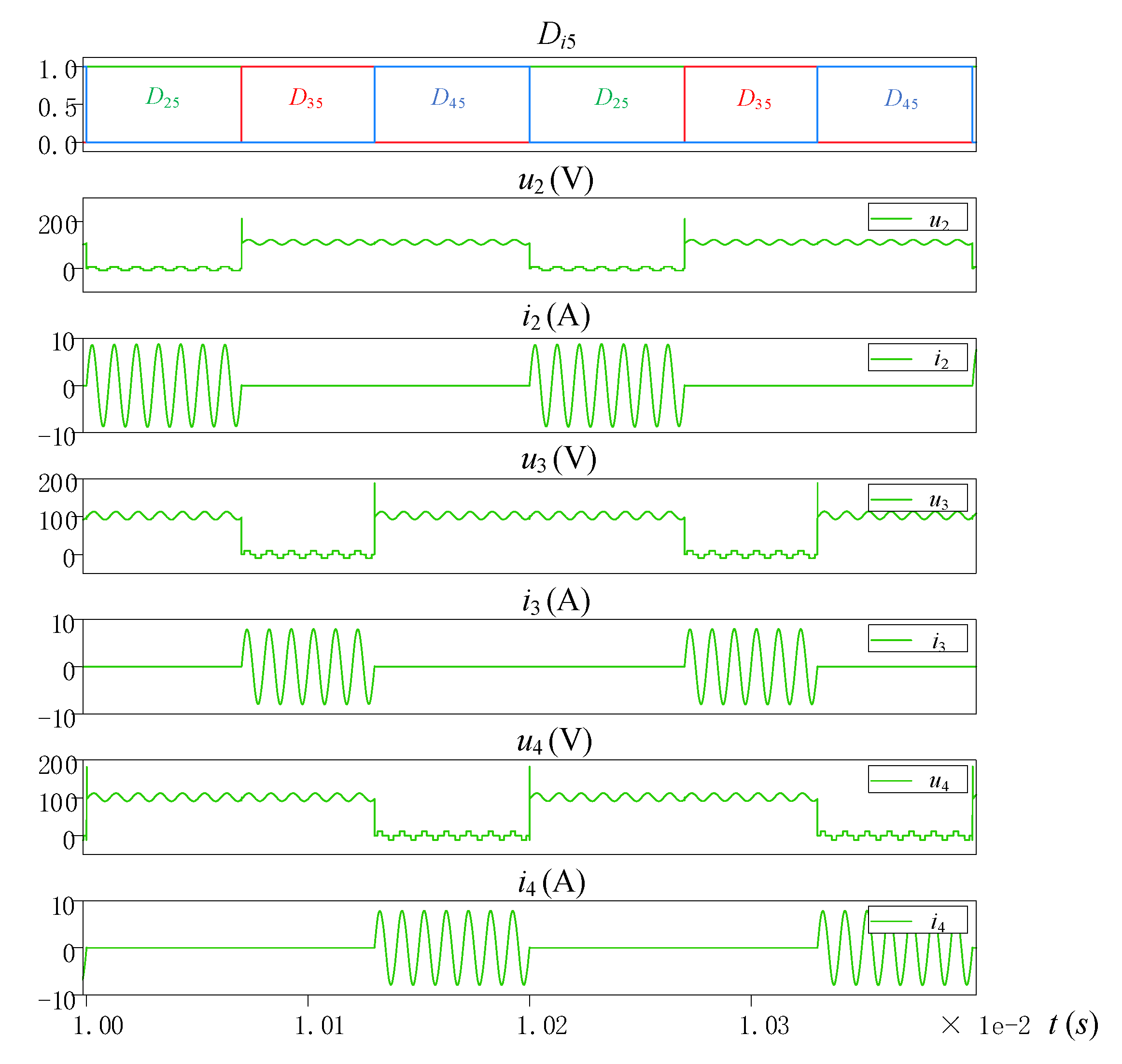
2.2. Cyclic Control of a TS-MRWPT System with Uncontrollable Rectifiers
3. Time-Sharing, Multiple-Receiver, Wireless Power Transfer System with Active-Bridge Rectifiers
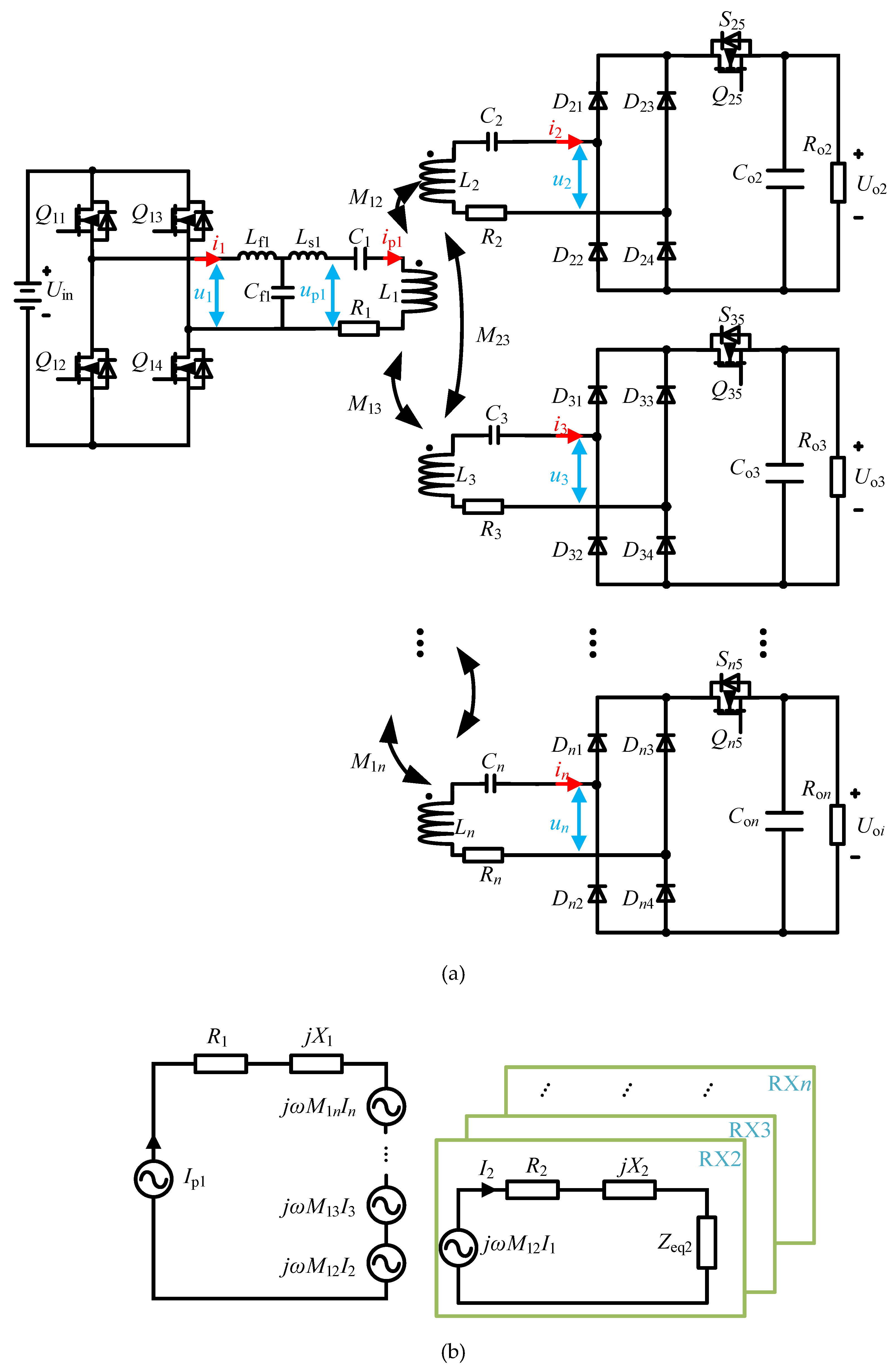
3.1. Modeling of the TS-MRWPT with Active-Bridge Rectifiers
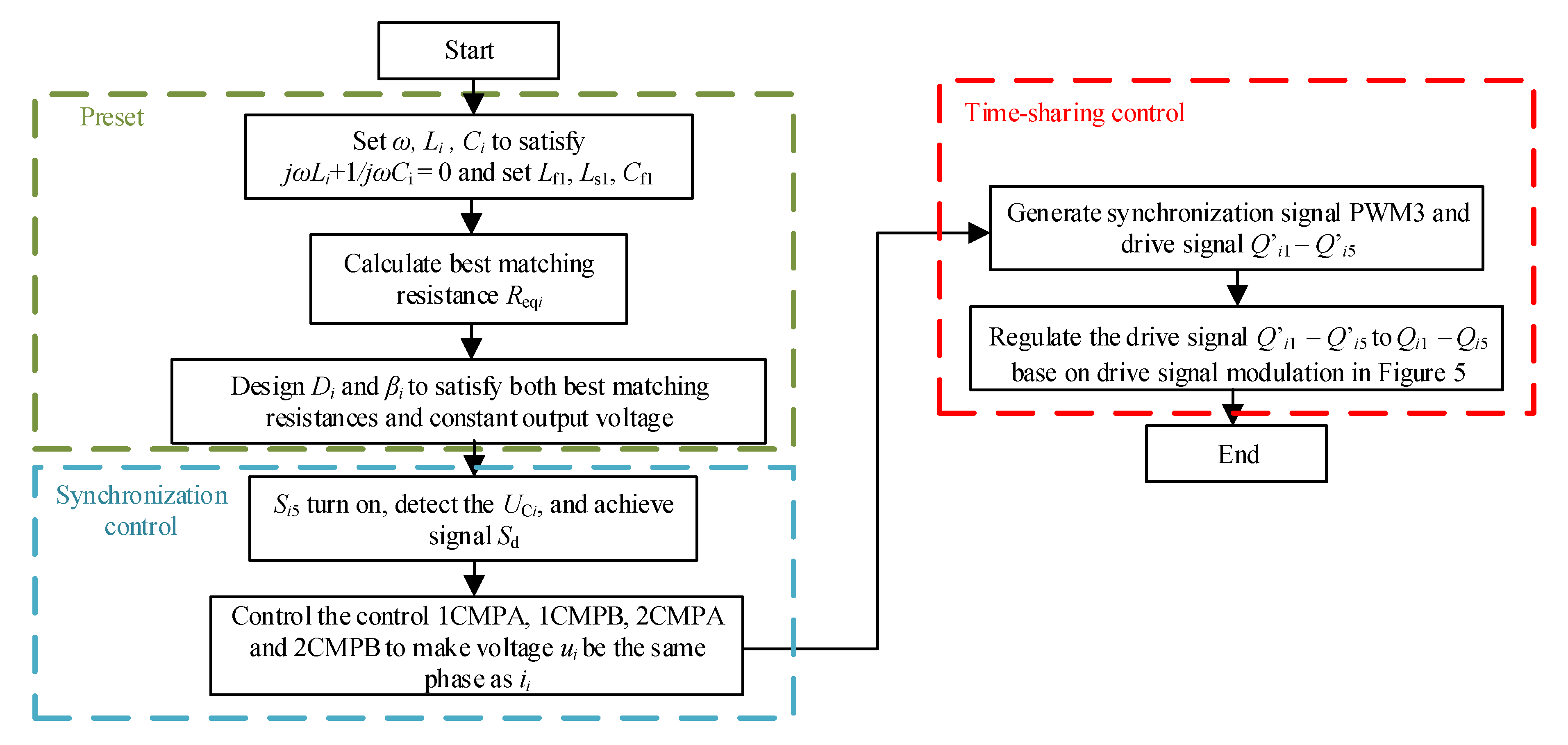
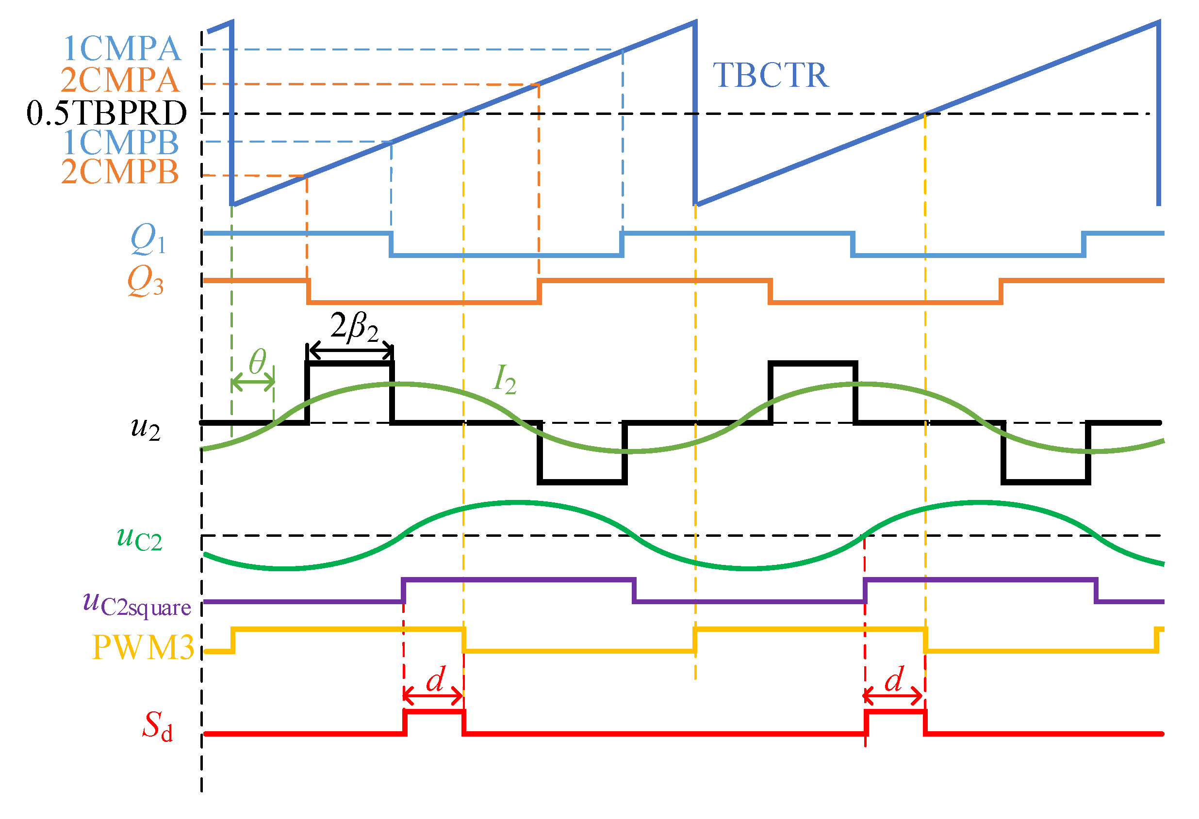
3.2. Cyclic Control for a Time-Sharing, Multiple-Receiver, Wireless Power Transfer System with Active-Bridge Rectifiers
- (1)
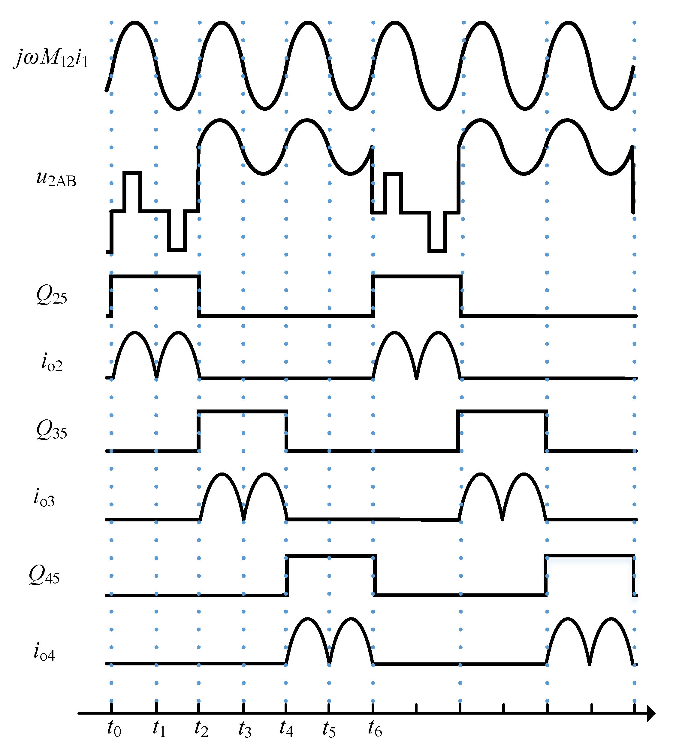
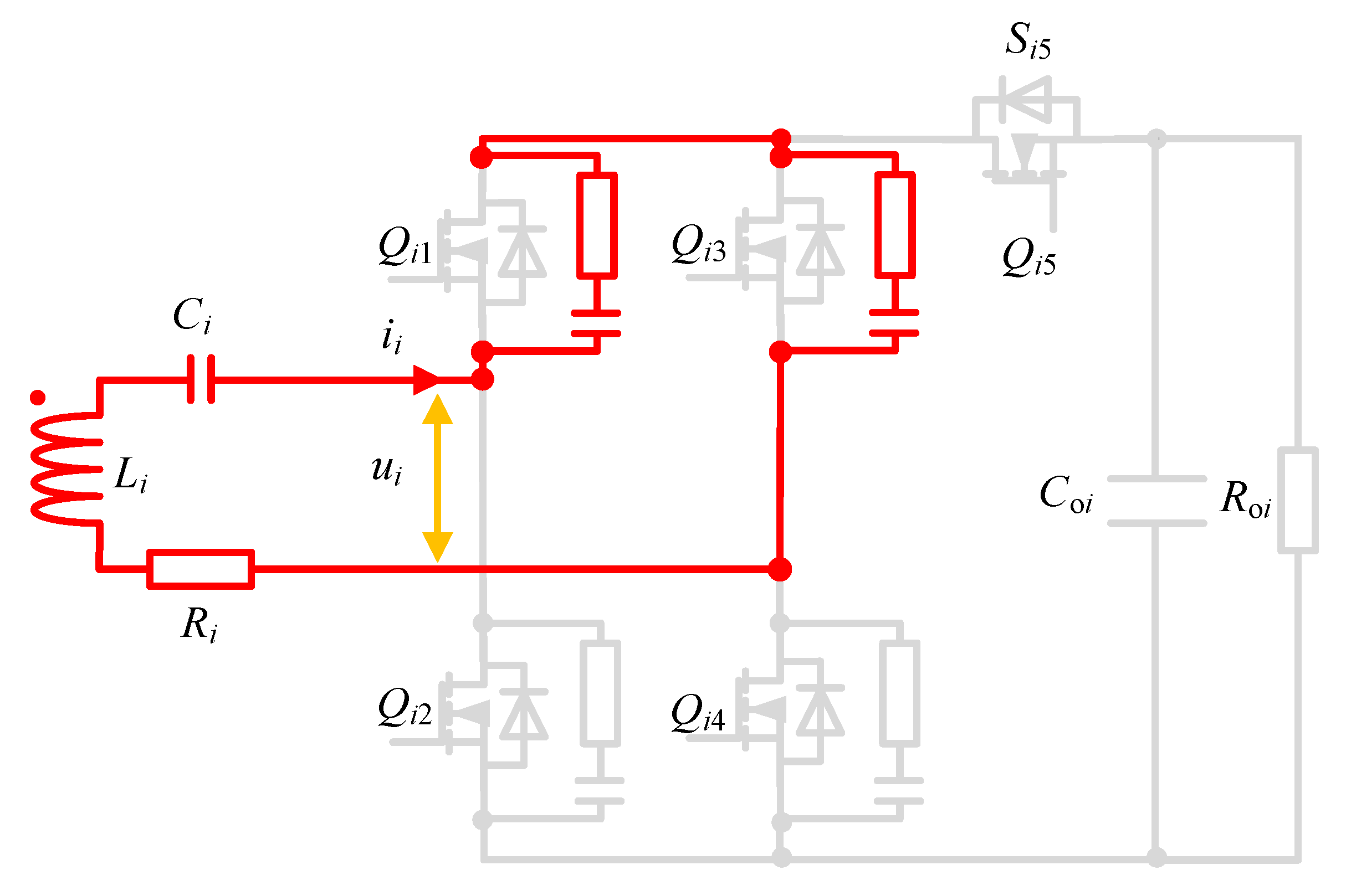
- Mode 1: Figure 8a displays the operating mode when ii > 0 (i = 2, 3, …, n) and Qi5 are set to a high level. The Si5 are turned on and the potential difference uAC is the turn-on voltage drop of the Si5. The current flow is Li-Ci-Di1-Si5-Roi (Coi)-Di4-Ri. The filter capacitance Coi are charging and the output voltage Uoi of the filter capacitance Coi are increasing. The voltage uCi(t) satisfies Equation (16). ii(t) and uCi(t) denote the instantaneous values of the resonant currents and voltages of the capacitances Ci in Figure 8.
- (2)
- Mode 2: Figure 8b displays the operating mode when ii = 0 (i = 2, 3, …, n) and Qi5 is set to a low level. The Si5 are turned off and the circuit of the receiver coils are open circuits. The potential difference is uAC = uAB − uoi, the current ioi is supported by the filter capacitance Coi, and the filter capacitance Coi is discharging. The current flow is Coi-Roi. For the currents ii = 0, the potential difference uAB is no longer equal to the resonant voltage and the capacitance voltage uCi remain at the voltage uCi(tmode1−). Therefore, the uCi in mode 2 in Equation (17) remains unchanged and is equal to the value of uCi(tmode1−), which is the voltage of the Ci at the end of mode 1. Moreover, the uCi(tmode1−) can be derived to give Equation (17) and the ω is the resonant angle frequency of the system, which is constant. The voltage uAB satisfies Equation (18). ip1(t) and uAB(t) denote the instantaneous current of the current ip1 in Figure 3 and the instantaneous potential difference of points A and B in Figure 8. Furthermore, tmodei− denotes the time when mode i ends.
- (3)
- Mode 3: Figure 8c displays the operating mode when ii < 0 (i = 2, 3, …, n) and Qi5 are set to a high level. The Si5 are turned on and the potential difference uAC is the turn-on voltage drop of Si5. The current flow is Li-Ci-Di3-Si5-Roi (Coi)-Di3-Ri. The filter capacitance Coi are charging and the voltage uoi of the filter capacity Coi are increasing. The voltage uCi satisfies Equation (16).
- (4)
- Mode 4: Figure 8d displays the operating mode when ii = 0 (i = 2, 3, …, n) and Qi5 are set to a low level. The Si5 are turned off and the circuit of the receiver coils are open circuits. The potential difference is uAC = uAB − uoi, the current ioi are supported by the filter capacity Coi, and the filter capacity Coi are discharging. The current flow is Coi-Roi. For the currents ii = 0, the voltage uCi satisfies Equations (19) and (20):
3.3. RC Absorbing Circuits for Time-Sharing, Multiple-Receiver Systems
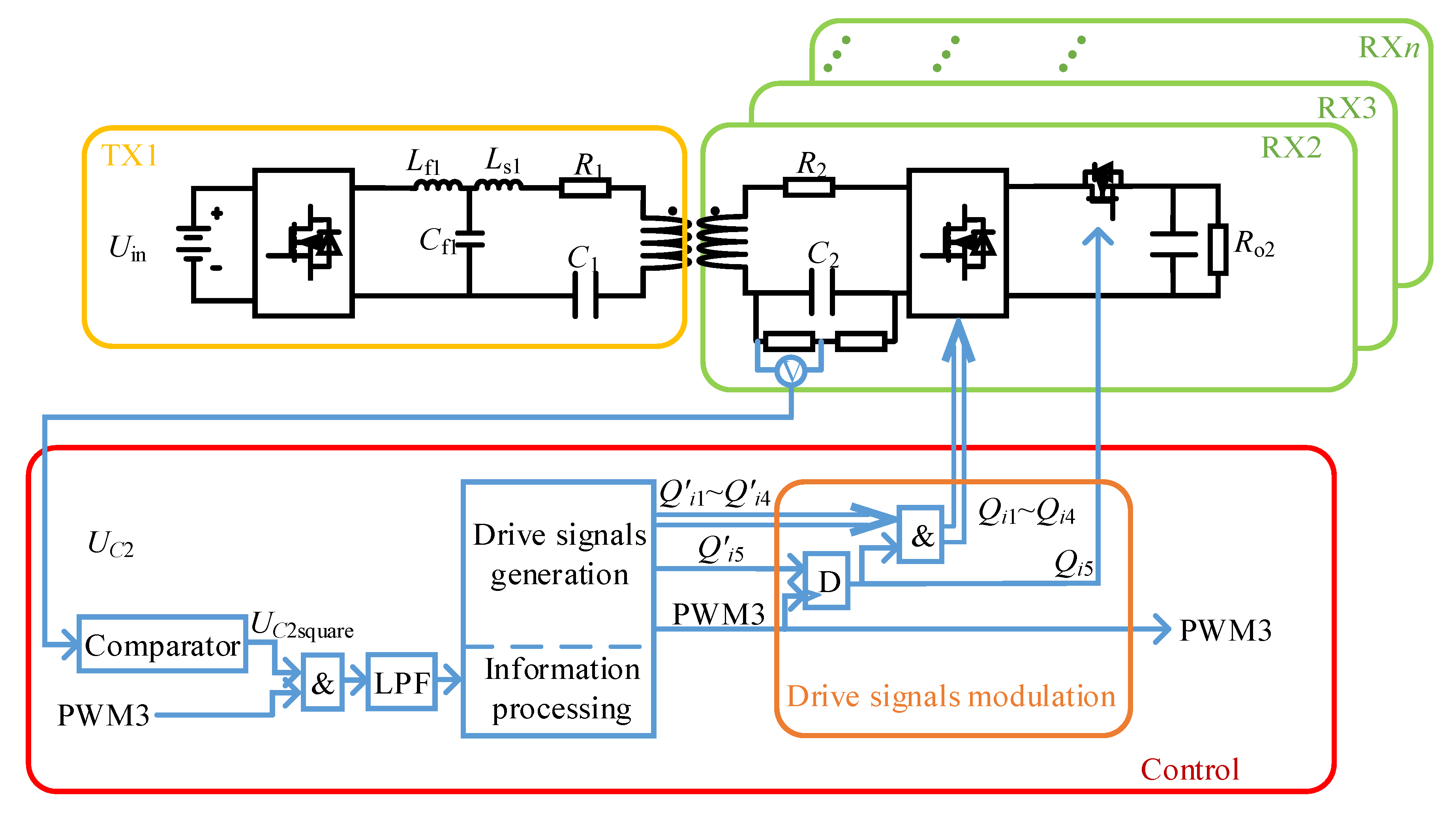
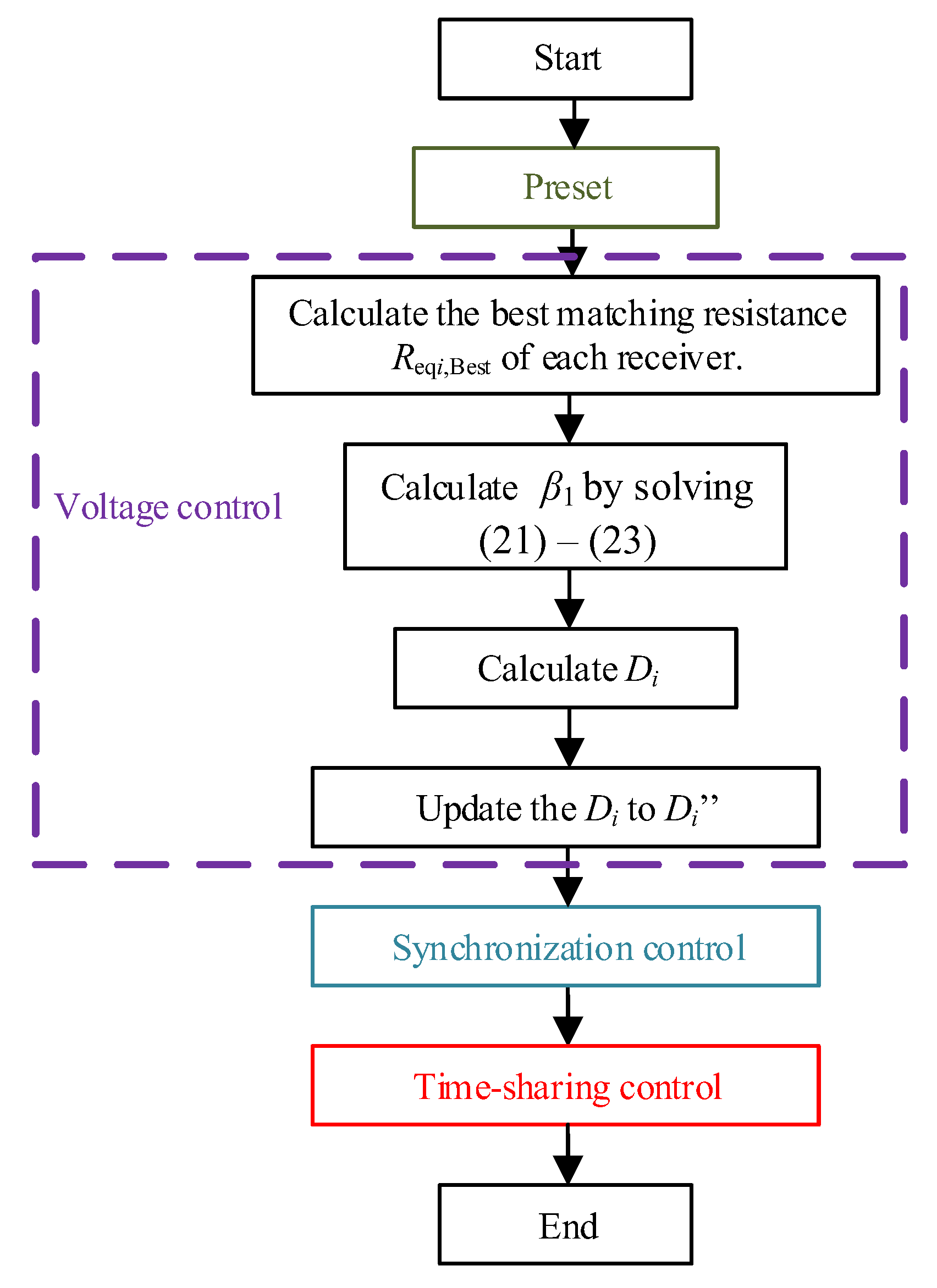
3.4. Output Voltage Control for Time-Sharing, Multiple-Receiver, Wireless Power Transfer Systems
4. Results
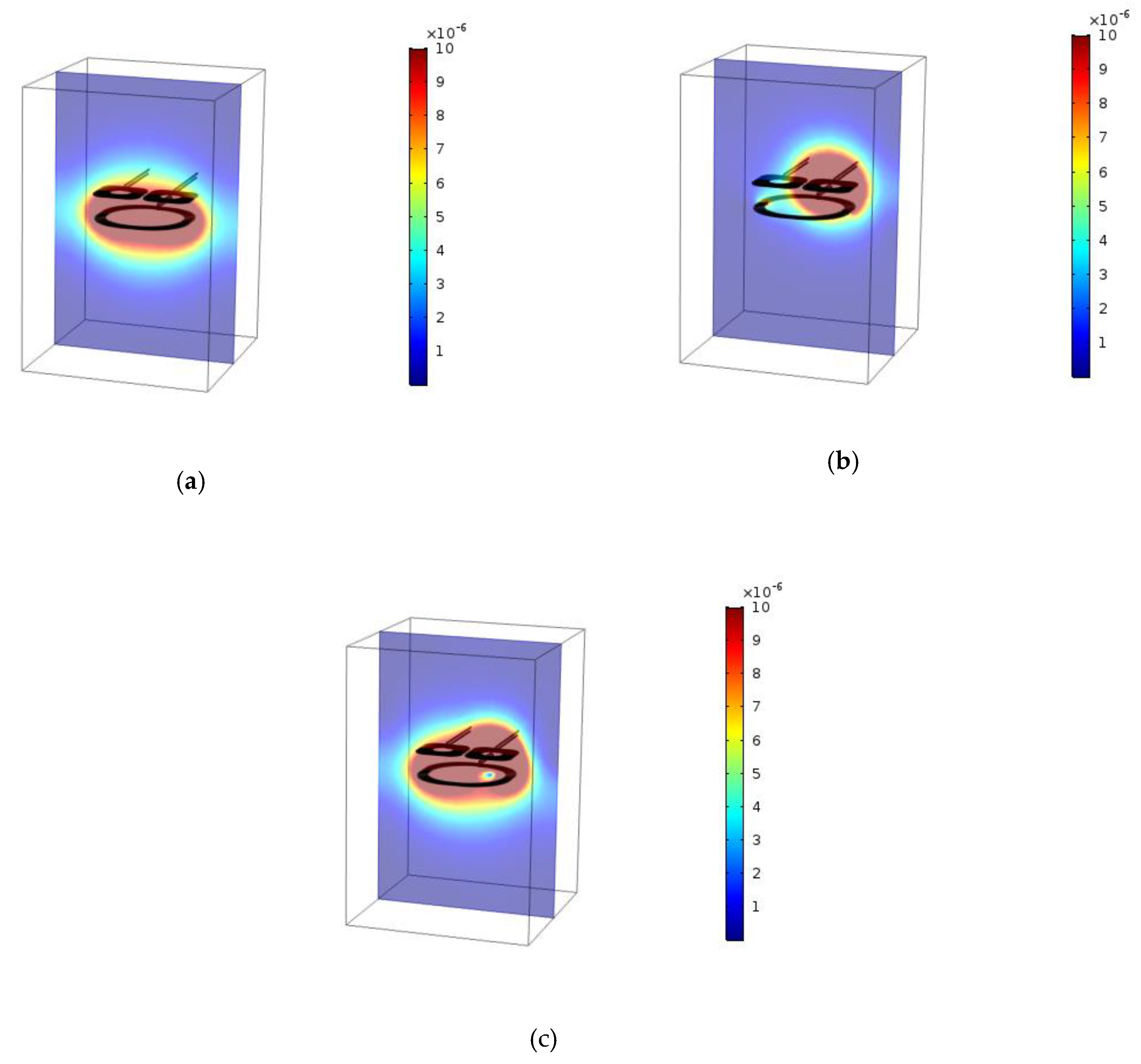
4.1. Simulation Result of the Cross-Coupling Effect
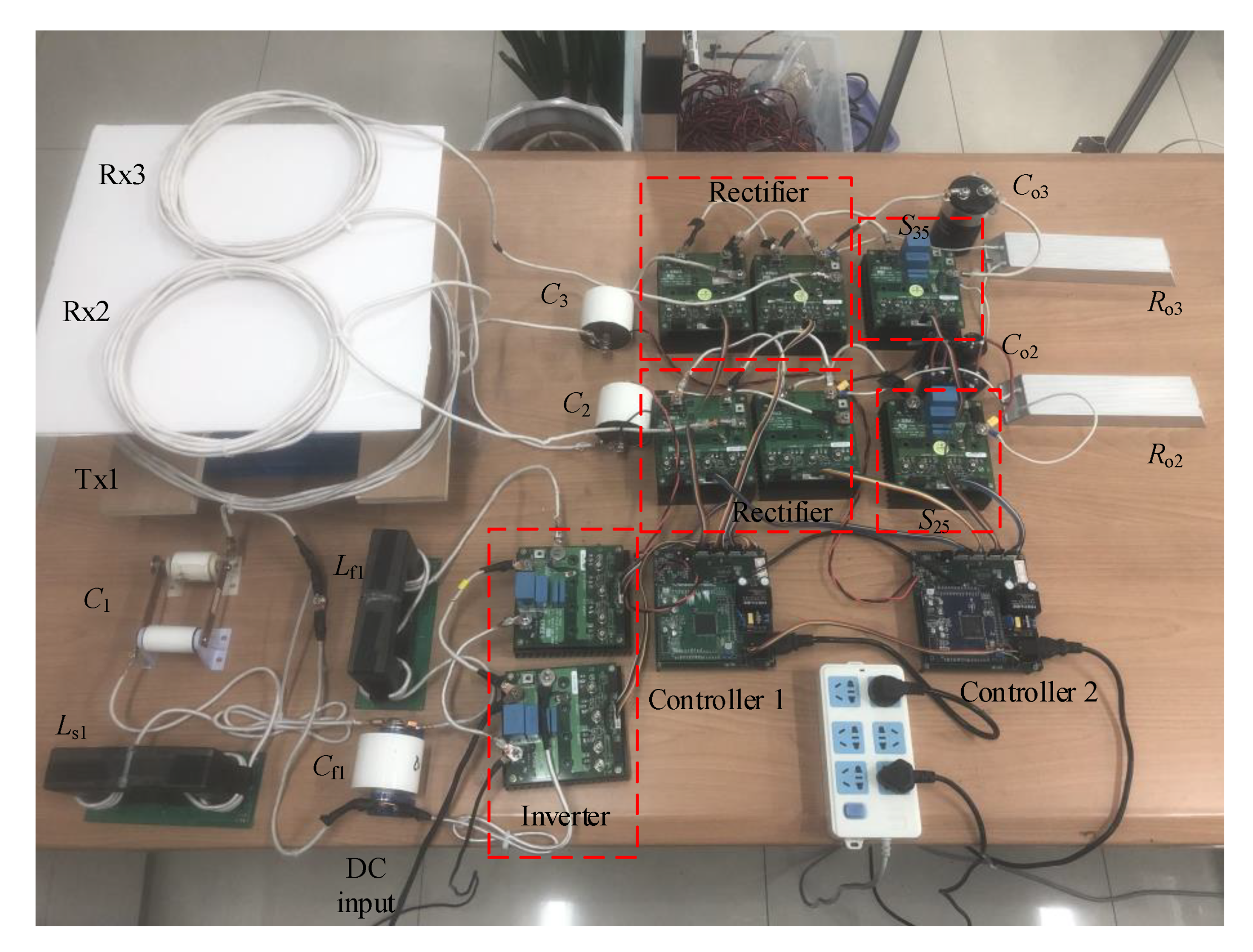
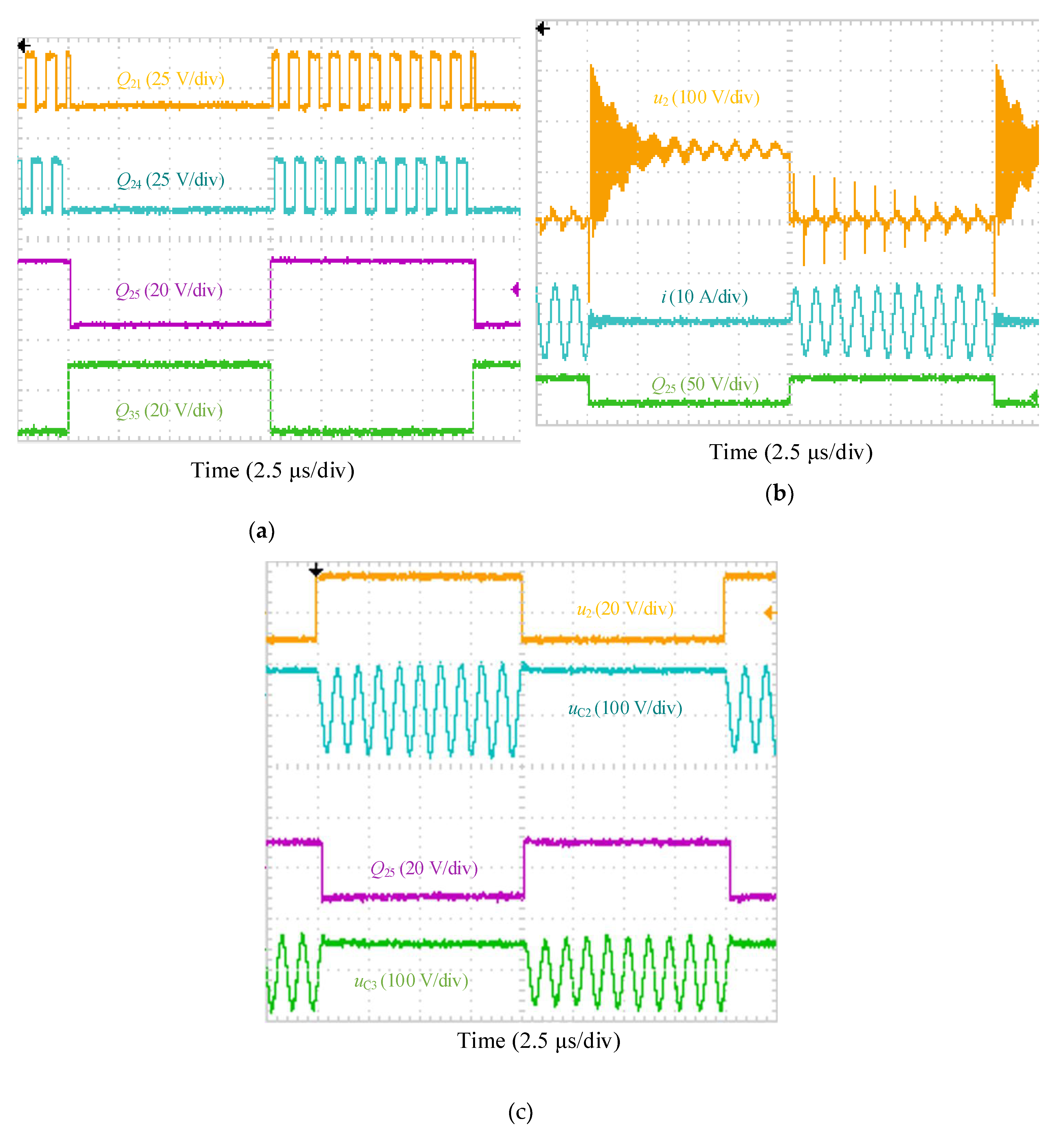
4.2. Simulation and Experimental Results of Time-Sharing, Multiple-Receiver WPT Systems
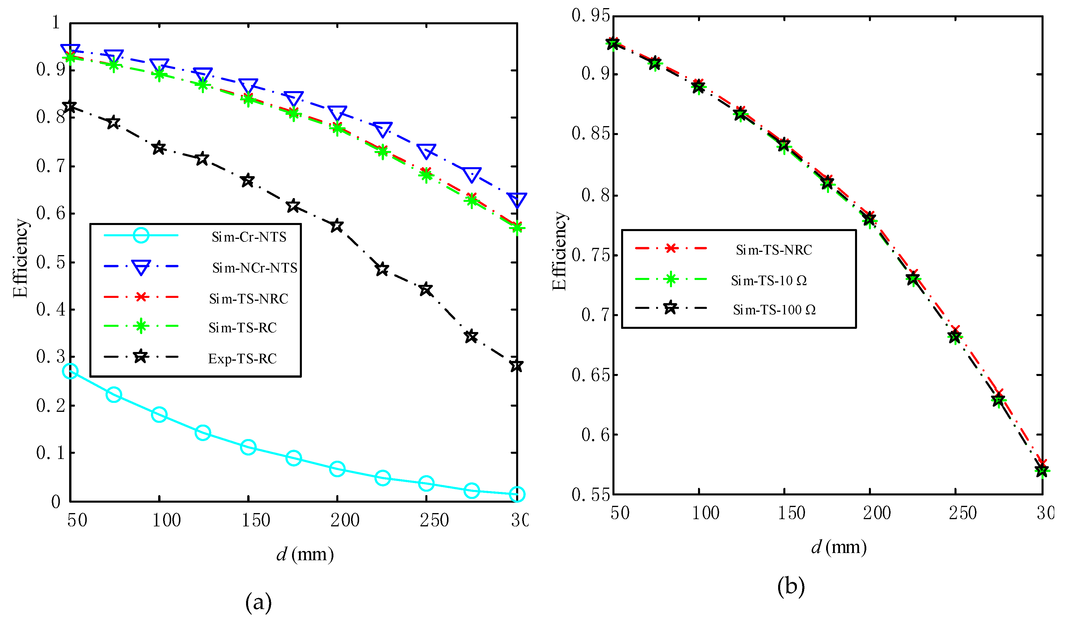
4.3. Simulation Comparison between the Time-Sharing Method and Compensation Method
4.4. Simulation Result of the Voltage Control of a Time-Sharing, Multiple-Receiver WPT System
5. Conclusions
Author Contributions
Funding
Conflicts of Interest
References
- Kuipers, J.; Bruning, H.; Bakker, S.; Rijnaarts, H. Near field resonant inductive coupling to power electronic devices dispersed in water. Sens. Actuators A Phys. 2012, 178, 217–222. [Google Scholar] [CrossRef]
- Niu, W.; Gu, W.; Chu, J.; Shen, A. Frequency splitting of underwater wireless power transfer. In Proceedings of the IEEE International Workshop on Electromagnetics: Applications and Student Innovation Competition, Nanjing, China, 16–18 May 2016; pp. 1–3. [Google Scholar]
- Si, P.; Hu, A.P.; Malpas, S.; Budgett, D. A frequency control method for regulating wireless power to implantable devices. IEEE Trans. Biomed. Circuits Syst. 2008, 2, 22–29. [Google Scholar] [CrossRef]
- Xue, R.F.; Cheng, K.W.; Je, M. High-Efficiency Wireless Power Transfer for Biomedical Implants by Optimal Resonant Load Transformation. IEEE Trans. Circuits Syst. I Regul. Pap. 2013, 60, 867–874. [Google Scholar] [CrossRef]
- Meng, M.; Kiani, M. A Hybrid Inductive-Ultrasonic Link for Wireless Power Transmission to Millimeter-Sized Biomedical Implants. IEEE Trans. Circuits Syst. II Express Briefs 2016, 64, 1137–1141. [Google Scholar] [CrossRef]
- Ramrakhyani, A.K.; Mirabbasi, S.; Mu, C. Design and optimization of resonance-based efficient wireless power delivery systems for biomedical implants. IEEE Trans. Biomed. Circuits Syst. 2011, 5, 48–63. [Google Scholar] [CrossRef] [PubMed]
- Klontz, K.W.; Divan, D.M.; Novotny, D.W.; Lorenz, R.D. Contactless power delivery system for mining applications. IEEE Trans. Ind. Appl. 1995, 31, 27–35. [Google Scholar] [CrossRef]
- Zhao, D.; Ding, E.J.; Xue, H. Multiple-Input Single-Output Wireless Power Transmission System for Coal Mine Application. Appl. Mech. Mater. 2014, 462–463, 900–904. [Google Scholar] [CrossRef]
- Tampubolon, M.; Pamungkas, L.; Chiu, H.J.; Liu, Y.C.; Hsieh, Y.C. Dynamic Wireless Power Transfer for Logistic Robots. Energies 2018, 11, 527. [Google Scholar] [CrossRef] [Green Version]
- Rajagopal, S.; Khan, F. Multiple Receiver Support for Magnetic Resonance Based Wireless Charging. In Proceedings of the 2011 IEEE International Conference on Communications Workshops (ICC), Kyoto, Japan, 5–9 June 2011; pp. 1–5. [Google Scholar]
- Cannon, B.L.; Hoburg, J.F.; Stancil, D.D.; Goldstein, S.C. Magnetic Resonant Coupling As a Potential Means for Wireless Power Transfer to Multiple Small Receivers. IEEE Trans. Power Electron. 2009, 24, 1819–1825. [Google Scholar] [CrossRef] [Green Version]
- Imura, T.; Hori, Y. Optimization using transmitting circuit of multiple receiving antennas for wireless power transfer via magnetic resonance coupling. In Proceedings of the 33rd International Telecommunications Energy Conference (INTELEC), Amsterdam, The Netherlands, 9–13 October 2011; pp. 1–4. [Google Scholar]
- Lee, S.; Kim, S.; Seo, C. Design of multiple receiver for wireless power transfer using metamaterial. In Proceedings of the Asia-Pacific Microwave Conference Proceedings (APMC), Seoul, South Korea, 5–8 November 2013; pp. 1036–1038. [Google Scholar]
- Cai, W.; Ma, D.; Tang, H.; Lai, X.; Liu, X.; Sun, L. Highly Efficient Target Power Control for Two-Receiver Wireless Power Transfer Systems. Energies 2018, 11, 2726. [Google Scholar] [CrossRef] [Green Version]
- Sun, L.; Tang, H.; Zhong, S. Load-Independent Output Voltage Analysis of Multiple-Receiver Wireless Power Transfer System. IEEE Antennas Wirel. Propag. Lett. 2016, 15, 1238–1241. [Google Scholar] [CrossRef]
- Fu, M.; Zhang, T.; Ma, C.; Zhu, X. Efficiency and Optimal Loads Analysis for Multiple-Receiver Wireless Power Transfer Systems. IEEE Trans. Microw. Theory Tech. 2015, 63, 801–812. [Google Scholar] [CrossRef]
- Fu, M.; Yin, H.; Zhu, X.; Ma, C. Analysis and Tracking of Optimal Load in Wireless Power Transfer Systems. IEEE Trans. Power Electron. 2015, 30, 3952–3963. [Google Scholar] [CrossRef]
- Berger, A.; Agostinelli, M.; Vesti, S.; Oliver, J.A.; Cobos, J.A.; Huemer, M. A Wireless Charging System Applying Phase-Shift and Amplitude Control to Maximize Efficiency and Extractable Power. IEEE Trans. Power Electron. 2015, 30, 6338–6348. [Google Scholar] [CrossRef]
- Li, H.; Li, J.; Wang, K.; Chen, W. A Maximum Efficiency Point Tracking Control Scheme for Wireless Power Transfer Systems Using Magnetic Resonant Coupling. IEEE Trans. Power Electron. 2015, 30, 3998–4008. [Google Scholar] [CrossRef]
- Li, Y.; Mai, R.; Liu, Y.; He, Z. Efficiency optimising strategy for dual-coupled transmitters based WPT systems. Electron. Lett. 2016, 52, 1877–1879. [Google Scholar] [CrossRef]
- Liu, X.; Wang, T.; Yang, X.; Jin, N.; Tang, H. Analysis and Design of a Wireless Power Transfer System with Dual Active Bridges. Energies 2017, 10, 1588. [Google Scholar] [CrossRef] [Green Version]
- Ahn, D.; Hong, S. Effect of Coupling Between Multiple Transmitters or Multiple Receivers on Wireless Power Transfer. IEEE Trans. Ind. Electron. 2013, 60, 2602–2613. [Google Scholar] [CrossRef]
- Kim, J.; Son, H.; Kim, D.; Park, Y. Impedance matching considering cross coupling for wireless power transfer to multiple receivers. In Proceedings of the 2013 IEEE Wireless Power Transfer (WPT), Perugia, Italy, 15–16 May 2013; pp. 226–229. [Google Scholar]
- Cui, D.; Imura, T.; Hori, Y. Cross coupling cancellation for all frequencies in multiple-receiver wireless power transfer systems. In Proceedings of the International Symposium on Antennas and Propagation (ISAP), Okinawa, Japan, 24–28 October 2016; pp. 48–49. [Google Scholar]
- Fu, M.; Zhang, T.; Zhu, X.; Luk, P.C.; Ma, C. Compensation of Cross Coupling in Multiple-Receiver Wireless Power Transfer Systems. IEEE Trans. Ind. Inf. 2016, 12, 474–482. [Google Scholar] [CrossRef]
- Jiang, C.; Chau, K.T.; Liu, C.; Han, W. Wireless DC Motor Drives with Selectability and Controllability. Energies 2017, 10, 49. [Google Scholar] [CrossRef]
- Kim, Y.; Ha, D.; Chappell, W.J.; Irazoqui, P.P. Selective Wireless Power Transfer for Smart Power Distribution in a Miniature-Sized Multiple-Receiver System. IEEE Trans. Ind. Electron. 2016, 63, 1853–1862. [Google Scholar] [CrossRef]
- Yanagawa, S.; Shimizu, R.; Hamada, M.; Kuroda, T. Wireless Power Transfer System for 3-D stacked Multiple Receivers Switching between Single and Dual Frequency Modes. In Proceedings of the 61st International Midwest Symposium on Circuits and Systems (MWSCAS), Windsor, ON, Canada, 5–8 August 2018; pp. 1046–1049. [Google Scholar]
- Yin, H.; Fu, M.; Zhao, C.; Ma, C. A decentralized charging control of a multiple-receiver wireless power transfer system using ultracapacitor semi-active topology. In Proceedings of the 25th International Symposium on Industrial Electronics (ISIE), Santa Clara, CA, USA, 8–10 June 2016; pp. 262–267. [Google Scholar]
- Jiang, C.; Chau, K.T.; Ching, T.W.; Liu, C.; Han, W. Time-Division Multiplexing Wireless Power Transfer for Separately Excited DC Motor Drives. IEEE Trans. Magn. 2017, 53, 1–5. [Google Scholar] [CrossRef]
- Juliet, V.; Padmanaban, S.; Mihet-Popa, L. Frequency Splitting Elimination and Cross-Coupling Rejection of Wireless Power Transfer to Multiple Dynamic Receivers. Appl. Sci. 2018, 8, 179. [Google Scholar] [CrossRef] [Green Version]
- Deng, J.; Deng, J.; Li, W.; Li, S.; Mi, C. Magnetic integration of LCC compensated resonant converter for inductive power transfer applications. In Proceedings of the Energy Conversion Congress and Exposition (ECCE), Pittsburgh, PA, USA, 14–18 September 2014; pp. 660–667. [Google Scholar]


| Coil | Turns | Length of Outer Square (mm) | Gap between Adjacent Lines (mm) | Width of Coil (mm) | Equivalent Conductivity of Wire (m·Ω) | Equivalent Resistance (mΩ) | Self-Inductance (μH) |
|---|---|---|---|---|---|---|---|
| Transmitter coil | 5 | 420 | 2 | 2 | 1.5 × 10⁶ | 17.439 | 17.535 |
| Receiver coil | 8 | 200 | 2 | 2 | 1.5 × 10⁶ | 15.433 | 18.103 |
| Symbol | Quantity | Value |
|---|---|---|
| L1, L2, L3 | Self-inductances of coils | 22.78 µH, 24,53 µH, 24.62 µH |
| Lf1, Ls1 | Inductances | 25.12 µH, 25.20 µH |
| C1, C2, C3, Cf1 | Compensation capacitors | 110 nF, 100 nF, 100 nF, 100 nF |
| Co2, Co3 | Filter capacitors | 2200 µF, 2200 µF |
| R1, R2, R3 | Parasitic resistances of coils | 21.74 mΩ, 17.03 mΩ, 17.53 mΩ |
| N1, N2, N3 | Turns of coils | 5, 8, 8 |
| r1, r2, r3 | Radius of coils | 420 mm, 200 mm, 200 mm |
| Ro2, Ro3 | Load resistances | 5 Ω, 5 Ω |
| f1 | Operating frequency | 100 kHz |
| f2 | Operating frequency | 5 kHz |
| M23 | Mutual inductance | 0.9660 µH |
| Coil | Turns | Length of Outer Square (mm) | Gap between Adjacent Lines (mm) | Width of Coil (mm) | Equivalent Conductivity of Wire (m·Ω) | Equivalent Resistance (mΩ) | Self-Inductance (μH) |
|---|---|---|---|---|---|---|---|
| Receiver coil | 7 | 130 | 2 | 2 | 1.5 × 10⁶ | 7.4915 | 5.0214 |
| Transmitter coil | 5 | 420 | 2 | 2 | 1.5 × 10⁶ | 15.433 | 18.103 |
| Method | Efficiency | |
|---|---|---|
| Position “B” | Position “C” | |
| Cross-coupling compensation method | 88.33% | 77.66% |
| Time-sharing method | 85.41% | 85.40% |
| Symbol | Quantity | Value |
|---|---|---|
| L1, L2, L3, L4 | Self-inductances of coils | 22.78 µH, 24,53 µH, 24,53 µH, 24,53 µH |
| Lf1, Ls1 | Inductances | 25 µH, 25 µH |
| C1, C2, C3, C4, Cf1 | Compensation capacitors | 110 nF, 100 nF, 100 nF, 100 nF, 100 nF |
| Co2, Co3, Co4 | Filter capacitors | 2200 µF, 2200 µF, 2200 µF |
| R1, R2, R3, R4 | Parasitic resistances of coils | 12.25 mΩ, 17.03 mΩ, 17.03 mΩ, 17.03 mΩ |
| Ro2, Ro3, Ro4 | Load resistances | 4 Ω, 8 Ω, 10 Ω |
| f1 | Operating frequency | 100 kHz |
| f2 | Operating frequency | 5 kHz |
| Uo2, Uo3, Uo4 | Target voltage | 8 V, 10 V, 12 V |
| M23, M24, M34 | Mutual inductance | 0.9660 µH |
© 2020 by the authors. Licensee MDPI, Basel, Switzerland. This article is an open access article distributed under the terms and conditions of the Creative Commons Attribution (CC BY) license (http://creativecommons.org/licenses/by/4.0/).
Share and Cite
Cai, W.; Ma, D.; Lai, X.; Hashmi, K.; Tang, H.; Xu, J. Time-Sharing Control Strategy for Multiple-Receiver Wireless Power Transfer Systems. Energies 2020, 13, 599. https://doi.org/10.3390/en13030599
Cai W, Ma D, Lai X, Hashmi K, Tang H, Xu J. Time-Sharing Control Strategy for Multiple-Receiver Wireless Power Transfer Systems. Energies. 2020; 13(3):599. https://doi.org/10.3390/en13030599
Chicago/Turabian StyleCai, Weikun, Dianguang Ma, Xiaoyang Lai, Khurram Hashmi, Houjun Tang, and Junzhong Xu. 2020. "Time-Sharing Control Strategy for Multiple-Receiver Wireless Power Transfer Systems" Energies 13, no. 3: 599. https://doi.org/10.3390/en13030599
APA StyleCai, W., Ma, D., Lai, X., Hashmi, K., Tang, H., & Xu, J. (2020). Time-Sharing Control Strategy for Multiple-Receiver Wireless Power Transfer Systems. Energies, 13(3), 599. https://doi.org/10.3390/en13030599