Article

Topology Selection and Parametric Design of Electromagnetic Vibration Energy Harvesters by Combining FEA-in-the-Loop and Analytical Approaches

1
Department of Robot Engineering, Keimyung University, Daegu 42601, Korea
2
Department of Mechatronics Engineering, Chungnam National University, Daejeon 34134, Korea
*
Author to whom correspondence should be addressed.
Energies 2020, 13(3), 627; https://doi.org/10.3390/en13030627
Submission received: 31 December 2019 / Revised: 27 January 2020 / Accepted: 30 January 2020 / Published: 2 February 2020

Abstract

:
Electromagnetic energy harvesters have been used to capture low-frequency vibration energy of large machines such as diesel generators. The structure of an electromagnetic energy harvester is either planar or tubular. Past research efforts focus on optimally designing each structure separately. An objective comparison between the two structures is necessary in order to decide which structure is advantageous. When comparing the structures, the design variations such as magnetization patterns and the use of yokes must also be considered. In this study, extensive comparisons are made covering all possible topologies of an electromagnetic energy harvester. A bench mark harvester is defined and the parameters that produce maximum output power are identified for each topology. It is found that the tubular harvesters generally produce larger output power than the planar counterparts. The largest output power is generated by the tubular harvester with a Halbach magnetization pattern (94.7 mW). The second best is the tubular harvester with axial magnetization pattern (79.1 mW) when moving yokes are inserted between permanent magnets for flux concentration. When cost is of primary concern, the tubular harvester with axial pattern may become a best option.

Graphical Abstract

1. Introduction

Extracting electrical power from the wasted sources is called energy harvesting or energy scavenging. For harvesting vibration energy, either piezoelectric or electromagnetic energy conversion can be used [1,2]. When high output power is required or the frequency of the vibration is low, electromagnetic harvesters are preferred to piezoelectric types [3,4]. An example of such cases is to harvest the vibration energy of diesel generators. Remote sites such as islands depend on diesel generators for electrical stability. Ships and submarines use diesel generators to supply electricity. Nuclear power plants are equipped with diesel generators to run coolant pumps if the electricity is cut off.
In many cases, it is important to monitor the status of these diesel generators. For example, it is critical to monitor the health of emergency generators in a nuclear power plant. When various sensors are deployed for status monitoring, it is sometimes impractical to provide power to them through wires [5]. For those cases, it would be necessary to have a local power source for increased reliability. Energy harvesters can fill this need.
Diesel generators also have distinctive vibration patterns. The largest vibration is related to the rigid body motion of the generator and the frequency of the vibration is in the range of 10 to 60 Hz [6,7]. Electromagnetic harvesters are ideal to convert the vibration of the diesel generators into electricity to power the wireless sensors since the harvester can be designed to capture the energy of the large rigid body motion at low frequency.
An electromagnetic vibration energy harvester consists of permanent magnet (PM) arrays and coils with or without yokes for flux concentration. The relative motion between the PM and coil induces voltage in the coil which is the source of harvested energy (generation). The induced voltage is then converted into a form that is appropriate for powering the output load (conversion). The performance of a harvester therefore depends not only on the generation but also on the conversion. Of course, the optimization of conversion is affected by many parameters such as the type and size of load, conversion circuit, the situation that the harvester is working [8,9]. As for the generation side, the induced voltage is determined by the structure of the harvester, the magnetization pattern, and the arrangement of the coil with respect to the PM array. The maximization of the induced voltage then concerns the optimization of these factors which is the topic of this paper.
The structure of the PM array is either planar or tubular. Previous studies on electromagnetic harvesters focus on optimizing either structure separately. For example, Zhu et al. optimized a planar harvester using Halbach arrays [10,11]. Tubular electromagnetic harvesters have also been optimized by Tang et al. [12] among others. However, little research has been done to quantitatively compare the tubular structure with the planar structure. No previous research has included the effects of the back irons (yokes) in the stator and in the permanent-magnet assembly at the same time for energy harvesters, which must be considered if the comparison can serve as an objective guideline on selecting the topology of an electromagnetic harvester.
To carry out the comparisons, experimental approach is impractical because there are too many design variations (e.g., tubular or planar structure, with or without yokes, Halbach or axial magnetization, etc.), and also because each design must be optimized with respect to parameters such as coil size and spacing. Analytical modeling similar to [13] is also very difficult since the geometries and structures are too complex and too diverse. Finite-element analysis (FEA) can deal with complex structures and is a useful tool for simulating the operation of a harvester. Past research has used FEA for optimizing harvester designs [12]. However, the computational cost of using FEA is too high for time-domain simulations that are need to obtain the output voltage from a harvester. This paper proposes a method of combining analytical relationships with the results from FEA, thereby greatly reducing the computational cost.
Using this method, the total of eight topologies of electromagnetic harvesters are compared in terms of the output power: all combinations of planar vs. tubular structures, axial vs. Halbach magnetization patterns, magnetic vs. nonmagnetic stator. For fair comparisons, each topology is optimized to generate maximum output power with the same volume of permanent magnets.
The content of the paper is as follows. The next section describes the underlying principles and the structures of the harvester considered in this paper. Section 3 deals with the method of combining analytical approach with FEA and the experimental validation of the method. Section 4 shows the comparison results and the issues that need to be discussed. Section 5 concludes the paper with concluding remarks.

2. Electromagnetic Vibration Energy Harvester

2.1. Energy Harvesting Principle

Illustrated in Figure 1 are the essential components of the electromagnetic energy harvester. An array of permanent magnets (PM) is suspended by mechanical springs. When the housing is attached to a vibrating structure such as diesel generators, the motion of the PM is amplified. The time rate of the magnetic field linked by the coil induces an electromotive force in the coil which is the source of the harvested energy. The equation of motion of the magnet is
m x ¨ m + c x ˙ m + k x m = m x ¨ b + F mag ,
where x m is the relative displacement of the PM with respect to the housing displacement, x b , and F mag is the magnetic force due to the coil current. The damping coefficient, c, includes both mechanical and electrical damping [13,14].
If the housing vibrates sinusoidally with the excitation frequency of ω ex , which can be expressed as
x b = X b sin ω ex t ,
the relative displacement of the PM is also sinusoidal, the amplitude of which is given as [15]
X m = X b r 2 ( 1 r 2 ) 2 + ( 2 ζ r ) 2 ,
where r is the ratio of the excitation frequency to the natural frequency ( k / m ), and the damping ratio is defined as
ζ = c 2 m k .
If the harvester is attached to a machine having a constant vibration frequency such as diesel generators, the spring constant can be adjusted so that the harvester vibrates at the resonance point ( r = 1 ) and the vibration amplitude is close to
X m X b 2 ζ .
Typically, the damping ratio is very small (less than 0.1). Therefore, the motion of the PM is amplified with respect to the base motion. The induced voltage in the coil is
V ind = N coil d ϕ d t ,
where N coil is the number of coil turns and ϕ is the magnetic flux linked by the coil.

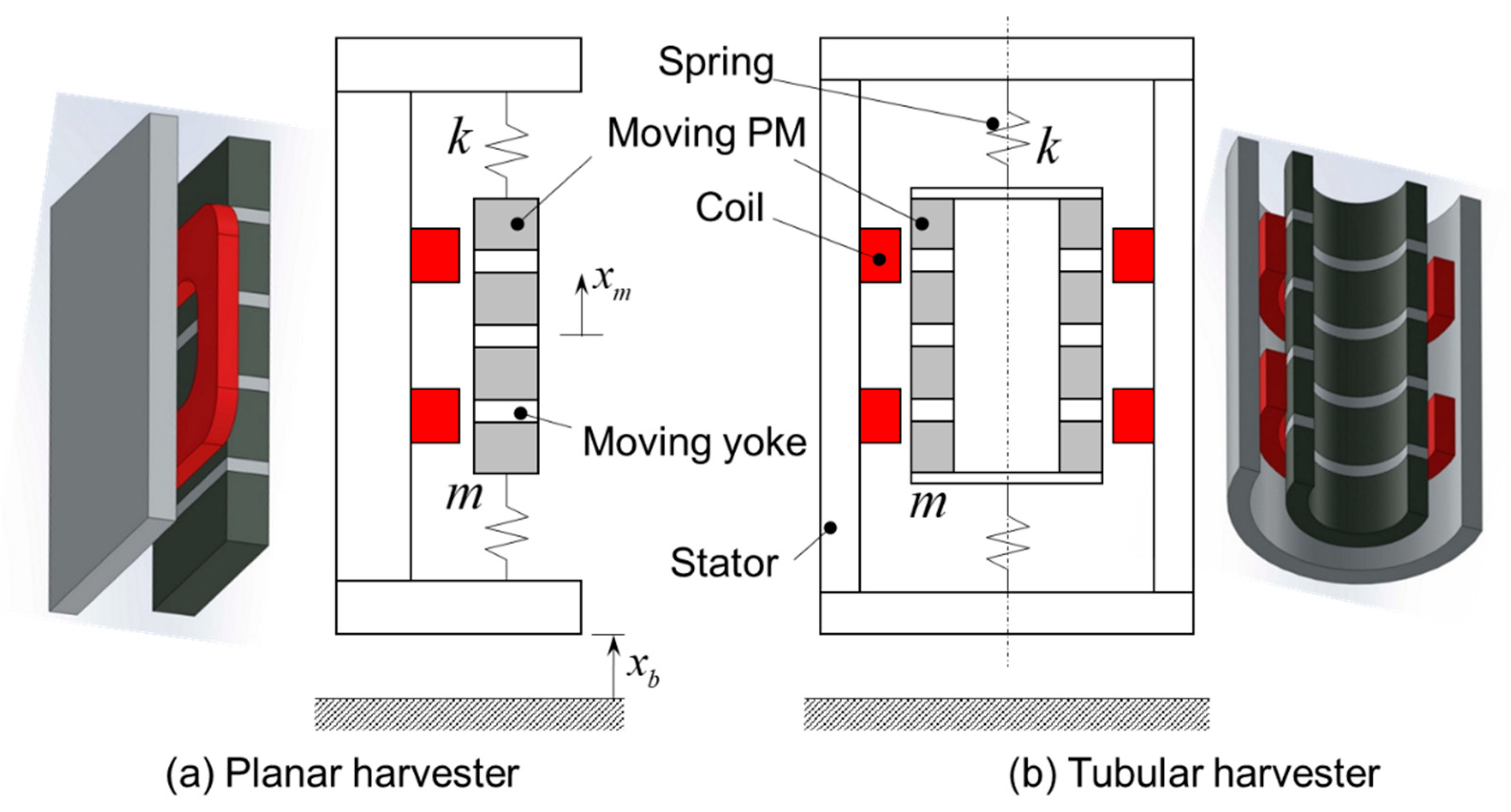
2.2. Design Alternatives

In literature, the geometry of the harvester is mostly either planar [3,10,11] or tubular [12,16,17]. As shown in Figure 2, both configurations consist of a mover (typically a PM array), a set of coils, and a stator for holding the coil set and for providing structural rigidity. When choosing a particular harvester geometry, a designer must be confident that the selected structure produces more output power than the other, using the same volume and at the same operating condition. We also need to know whether the use of back irons (yokes) is beneficial or not. When a PM array is used as a mover, the magnetization pattern of the array is also important for several reasons. Obviously, the magnetization pattern affects the output power of the harvester. It is also necessary to take such factors into consideration as the ease of manufacturability and the cost.
As illustrated in Figure 3, two magnetization patterns are used: axial and Halbach patterns. Although it is well known that the Halbach pattern increases the harvester output power [10,11], it is important for a designer to be able to assess the gain in the output power by adopting a more complex magnetization pattern. It is also useful to know how much the harvester output power would change depending on whether the stator material is magnetic or not. Once the structure and the magnetization pattern of the harvester are decided, the design parameters must be determined. For a fair comparison, it is critical that each design alternative must be optimized before being compared with others.
Figure 3 also shows some of the design parameters. Assuming that the overall volume of the harvester is fixed, the coil separation distance, c s , and the size of the moving yoke, w m y are selected for optimization. In summary, for the planar and tubular harvesters, four different configurations are considered: axial vs. the Halbach magnetization patterns and magnetic vs. nonmagnetic stator. Each configuration is optimized in terms of c s and w m y to find the largest attainable output power. A comparison is made for these eight optimized configurations.

3. Analysis Method and Optimization

3.1. Analysis Method

If the geometry is simple or the design variations are limited, analytical models of the harvester can be derived for the purpose of optimization as in [13]. However, it is rather impractical to obtain the mathematical models of all eight configurations considered in this paper. The presence of the moving yoke makes the modeling especially difficult since the magnetic flux inside the moving yokes change drastically both in the magnitude and in the direction. In this paper, the distribution of the magnetic field is obtained using finite element analyses (FEA). A public domain solver, Finite Element Method for Magnetics (FEMM) [18], is used for this purpose. Once the flux distribution is obtained from FEA, the induced voltage can be calculated by noting that
V ind = N coil d ϕ d t = N coil ϕ x m x m t .
If the vibration is sinusoidal in the form of
x m = X m sin ω e x t ,
the induced voltage is then
V ind = N coil ( ϕ x m ) X m ω e x cos ω e x t .
The root-mean-square (RMS) output voltage across the load resistance can be approximated as
V out , rms = R load R coil + R load V ind , rms .
Thus, the output power can be written as
P out = R load V ind , rms 2 ( R coil + R load ) 2 .
Here, the coil resistance is dependent on the design parameters. If we suppose that three phase coils are fully packed, we can determine the width of the coil separation. The coil cross-section area is then
A c = ( h g ) c s / 2 .
The number of coil turns can be determined by
N coil = f c A c A coil ,
where A coil is the cross-sectional area of a single coil and f c is the packing factor which is typically around 0.5 to 0.7 for round wires. For planar harvesters, the coil resistance is estimated by
R coil = ρ C u N coil 2 ( 2 l m + 4 π c s / 3 ) f c A c ,
where ρ C u is the resistivity of copper [13]. It is assumed that the end turns follow a half circle. The median length of the end turns is added to the resistance estimation. For tubular harvesters, the coil resistance equation is somewhat simpler because end turns are not necessary:
R coil = ρ C u N coil 2 4 π r avg f c A c ,
where r avg is the average radius of the coil.
Figure 4 summarizes the analysis steps to calculate the output power of the harvester. For each configuration, a total of 900 cases of design variations are considered: 30 cases of moving yoke and 30 cases of coil separation. Since eight configurations are considered, the total of 7200 design cases are evaluated using FEA in this paper.

3.2. Validation of the Method

To reduce the computation time, the geometry analyzed in the FEA is simplified and consists of only the stator, coil, and the PM array. The actual harvester has other components such as springs, bolts, and side panels that may affect the output power of the harvester by distorting the magnetic field. Therefore, it is necessary to show that the output power from the FEA is comparable to that of the actual harvester. For this purpose, a prototype harvester is built. The parameters of the prototype harvester are summarized in Table 1.
Actual pictures of the harvester are shown in Figure 5. The harvester was mounted on a vibration shaker (VS-120-06, IMV Corp., Japan) and excited at various frequencies including 10.5 Hz which is the natural frequency. The vibration of the PM mover was measured by an accelerometer (DeltaTronType4397, Brüel&Kjær, Denmark). The open-circuit output voltage was measured by a digital storage oscilloscope at the sampling rate of 10 kHz. A sample waveform of the open-circuit voltage is shown in Figure 6. The RMS output voltage was then computed by
V out , rms = 1 N k = 1 N V k , out 2 ,
where N is the number of sampled voltages. The measurements were repeated 10 times for each excitation frequency. The variability of the open-circuit voltages were calculated from these 10 measurements. Table 2 shows the measured voltages and the variability (measurement uncertainty). The variability was at most 4% of the RMS voltage.
The RMS open-circuit voltage calculated by the method in the preceding section was obtained by using Equation (16). The RMS voltages by FEA were compared with the measured ones in Table 2. The excitation frequencies were 10.5 Hz, 10.6 Hz, 11 Hz, and 12 Hz. The error between the measured voltage and the predicted voltage was calculated by
Error ( % ) = | V measured V predicted | V measured × 100
The errors of cases were below 10%. Based on these results, it was assumed that the method of using FEA for calculating the output power was valid for the purpose of comparisons.

4. Results and Discussions

For the purpose of comparisons, the reference design of the harvester was defined as follows. It was assumed that the excitation frequency was 10 Hz, which was the first mode frequency of a 12-pole diesel generator producing 60-Hz electricity. The axial length, w m , of PM assembly was 20 mm. The thickness, h m , was 5 mm. It was assumed that the mover mass was identical with or without the moving yoke. This was a reasonable assumption because iron is only 5% heavier than neodymium-iron-boron (NdFeB) magnets. Even if 50% of PM was replaced with yoke iron, the mass would change only by 2.5%, thereby negligibly affecting the natural frequency. The gap, h, between the PM assembly and the stator was 5 mm. The inner radius of tubular PM assembly was 7.5 mm. The depth of planar PM assembly was 62.8 mm so that the PM volumes of two structures were the same. The vibration amplitude of the PM array, X m , was 10 mm. The number of PM layers was four.
All eight topologies were optimized with respect to the moving yoke size and the coil separation distance. Figure 7 shows the optimization results of four topologies of the planar structure, while Figure 8 summarizes the results of four topologies of the tubular structure. Four rows in Figure 7 correspond to each topology of planar structure. For example, the first row is the power variation of the planar harvester having axial magnetization pattern with nonmagnetic stator. On the left, the 3D plot illustrates the overall trend of power variation with respect to the coil separation distance ( c s ) and the moving yoke size ( w m y ). On the left of each row, a 2D graph showing power variation with respect to the coil separation distance is provided to quantitatively compare the performance of differing topologies. Two representative cases of moving yoke sizes are displayed in the 2D graphs: one where maximum power is obtained and the other when the moving yoke size is largest (smallest overall power).
The two ridges in the top two rows of Figure 7 revealed that two local maxima existed with respect to the coil separation distance, one at small and the other at large coil separation distance, when the magnetization pattern was axial. Small coil separation distance enclosed fast-changing flux variations. However, more flux was encompassed by larger coil distance, which resulted in higher output power.
The maximum power for the case of the top row of Figure 7 (planar structure, axial pattern, nonmagnetic stator) was 31.1 mW when the moving yoke size was 0.8 mm and the coil separation distance was 16.9 mm. The presence of the moving yoke slightly increased the output power. The moving yoke concentrated the magnetic flux up to a certain level, but decreased the overall flux density if it was too large. When the stator was made of magnetic material, the maximum was increased to 51.4 mW as shown in the second row of Figure 7. The maximum occurred at the same point as that of the case with no stator. The magnetic stator decreased the reluctance of the flux path. Therefore, the level of the overall flux density increased with the magnetic stator.
If the magnetization pattern was Halbach (third and fourth rows in Figure 7), the maximum occurred when the size of the moving yoke was zero, which meant that the presence of the moving yoke decreased the output power. Researchers have shown that the Halbach pattern produces the largest output power for planar structure [10,11] and that the moving yokes tend to concentrate magnetic field for axial pattern but disrupt the already focused field distribution of the Halbach pattern. However, the magnetic stator is advantageous even for the Halbach pattern. When the stator was nonmagnetic, the maximum was 44.2 mW with the coil separation distance of 11.3 mm as shown in the third row of Figure 7. The magnetic stator increased the output power as can be seen in the fourth row of Figure 7. The maximum output power was 77.8 mW.
The results for the tubular harvesters follow similar trends. The top row of Figure 8 is the case of the tubular harvester with axial magnetization pattern. The stator is nonmagnetic. The maximum output power was 50.8 mW. The optimal point was the same as the planar case. If the stator was magnetic, the maximum increased to 79.1 mW (the second row of Figure 8). As was the case for the planar structure, the Halbach magnetization pattern increased the output power: 60.4 mW for the nonmagnetic stator (the third row of Figure 8) and 94.7 mW for the magnetic stator (the fourth row of Figure 8). The PM array without any moving yoke produced the maximum output power since the moving yokes distorted the concentrated field distribution of Halbach pattern.
For both planar and tubular structures, the adoption of magnetic stator was advantageous in comparison with the cases of a nonmagnetic stator. However, the increase was more prominent for the planar harvester than the tubular ones. Tubular harvesters with magnetic stator produced a little over 50% more output power than the ones with a nonmagnetic stator. In the case of the planar harvester, the increase was 65% for the axial pattern, and 76% for the Halbach pattern. Table 3 summarizes the largest attainable output power of all eight topologies.
Not only did the tubular harvesters produce higher output power than the planar counterparts, but they also had another advantage. Since the tubular coils could be constructed without end-turns, the tubular structure was more efficient than the planar structure. The main concern for the tubular harvester with a Halbach pattern was that it employs a radially-magnetized PM which is difficult to manufacture and expensive. A brief market survey revealed that a radially-magnetized PM costs about 15 times more than similarly-sized axial PM.

5. Conclusions

In this study, an extensive investigation was carried out to compare the topologies of electromagnetic vibration energy harvesters. Eight topologies were considered by mixing the structure shape, the magnetization patterns, and the stator material. Each topology was optimized to find the largest attainable output power.
If was found that a tubular harvester with a Halbach magnetization pattern was the best topology if the stator is made of magnetic material. If the cost of radially-magnetized magnets is a barrier, a tubular harvester with axial magnetization pattern is an economical alternative with the right size of moving yokes. Even a planar harvester with a Halbach magnetization pattern is a viable option if the application requires planar structure.

Author Contributions

Conceptualization, S.-y.Y., Y.-W.P. and M.N.; methodology, S.-y.Y.; software, S.-y.Y.; validation, M.N.; data curation, S.-y.Y.; writing—original draft preparation, M.N. and Y.-W.P.; writing—review and editing, Y.-W.P. All authors have read and agreed to the published version of the manuscript.

Funding

This research was partially funded by the research fund of Chungnam National University.

Conflicts of Interest

The authors declare no conflict of interest.

References

  1. Priya, S.; Inman, D.J. (Eds.) Energy Harvesting Technologies; Springer: New York, NY, USA, 2009; p. 42. [Google Scholar]
  2. Mitcheson, P.D.; Yeatman, E.M.; Rao, G.K.; Holmes, A.S.; Green, T.C. Energy harvesting from human and machine motion for wireless electronic devices. Proc. IEEE 2008, 96, 1457–1486. [Google Scholar] [CrossRef] [Green Version]
  3. Qiu, J.; Liu, X.; Chen, H.; Xu, X.; Wen, Y.; Li, P. A low-frequency resonant electromagnetic vibration energy harvester employing the Halbach arrays for intelligent wireless sensor networks. IEEE Trans. Magn. 2015, 51, 1–4. [Google Scholar]
  4. Paulides, J.J.; Jansen, J.W.; Encica, L.; Lomonova, E.A.; Smit, M. Power from the people. IEEE Ind. Appl. Mag. 2011, 17, 20–26. [Google Scholar] [CrossRef]
  5. Seah, W.K.; Eu, Z.A.; Tan, H.P. Wireless sensor networks powered by ambient energy harvesting (WSN-HEAP)-Survey and challenges. In Proceedings of the IEEE International Conference on Wireless VITAE, Aalborg, Denmark, 17–20 May 2009; pp. 1–5. [Google Scholar]
  6. Kim, M.K.; Choun, Y.S.; Seo, J.M. Demonstration of the vibration control performance of coil spring-viscous damper systems by measuring the vibration of an emergency diesel generator. J. Vib. Control 2010, 16, 207–229. [Google Scholar] [CrossRef]
  7. Clarke, H.; Stainsby, J.; Carden, E.P. Operational modal analysis of resiliently mounted marine diesel generator/alternator. In Rotating Machinery, Structural Health Monitoring, Shock and Vibration; Springer: New York, NY, USA, 2011; Volume 5, pp. 237–244. [Google Scholar]
  8. Tse, K.H.K.; Chung, H.S. MPPT for Electromagnetic Energy Harvesters Having Non-Negligible Output Reactance Operating Under Slow-Varying Conditions. IEEE Trans. Power Electron. 2019. [Google Scholar] [CrossRef]
  9. Shousha, M.; Dinulovic, D.; Haug, M.; Petrovic, T.; Mahgoub, A. A power management system for electromagnetic energy harvesters in battery/batteryless applications. IEEE J. Emerg. Sel. Top. Power Electron. 2019. [Google Scholar] [CrossRef]
  10. Zhu, D.; Beeby, S.; Tudor, J.; Harris, N. Vibration energy harvesting using the Halbach array. Smart Mater. Struct. 2012, 21, 075020. [Google Scholar] [CrossRef]
  11. Zhu, D.; Beeby, S.; Tudor, J.; Harris, N. Increasing output power of electromagnetic vibration energy harvesters using improved Halbach arrays. Sens. Actuators A Phys. 2013, 203, 11–19. [Google Scholar] [CrossRef] [Green Version]
  12. Tang, X.; Lin, T.; Zuo, L. Design and optimization of a tubular linear electromagnetic vibration energy harvester. IEEE ASME Trans. Mechatron. 2014, 19, 615–622. [Google Scholar] [CrossRef]
  13. Lee, H.; Noh, M.D.; Park, Y.W. Optimal design of electromagnetic energy harvester using analytic equations. IEEE Trans. Magn. 2017, 53, 1–5. [Google Scholar] [CrossRef]
  14. Stephen, N.G. On energy harvesting from ambient vibration. J. Sound Vibr. 2006, 293, 409–425. [Google Scholar] [CrossRef] [Green Version]
  15. Rao, S.S. Mechanical Vibration, 5th ed.; Pearson: Singapore, 2011; pp. 154–196. [Google Scholar]
  16. Munaz, A.; Lee, B.C.; Chung, G.S. A study of an electromagnetic energy harvester using multi-pole magnet. Sens. Actuators A Phys. 2013, 201, 134–140. [Google Scholar] [CrossRef]
  17. Halim, M.A.; Cho, H.; Park, J.Y. Design and experiment of a human-limb driven, frequency up-converted electromagnetic energy harvester. Energy Conv. Manag. 2015, 106, 393–404. [Google Scholar] [CrossRef]
  18. Finite Element Method Magnetics (FEMM). Available online: http://www.femm.info (accessed on 30 December 2019).
Figure 1. Schematic diagram of a planar electromagnetic energy harvester.
Energies 13 00627 g001
Figure 2. (a) Planar energy harvester. (b) Tubular energy harvester.
Energies 13 00627 g002
Figure 3. Magnetization patterns considered in this paper: (a) Axial (b) Halbach
Energies 13 00627 g003
Figure 4. Block diagram of the finite element analyses (FEA)-in-the-loop analysis for calculating the power output of the harvester
Energies 13 00627 g004
Figure 5. On the left is a picture of the harvester used for validation of the method. The harvester consists of springs, a coil, and a mover which carries PM array. The magnetization pattern of PM array is Halbach which is shown in the right picture. The coil is hidden beneath the mover. An accelerometer measures the vibration of the mover. A set of low-friction roller guides ensure vertical motion.
Energies 13 00627 g005
Figure 6. A sample open-circuit voltage measured from a prototype harvester. The excitation frequency is 10.5 Hz.
Energies 13 00627 g006
Figure 7. The variations of output power of planar harvesters. The top row is the case of axial PM array with nonmagnetic stator. The second row is for axial PM array with magnetic stator. The third and fourth row are the cases of the Halbach PM array with and without magnetic stator, respectively. Each row shows the variation of the output power with respect to coil separation and moving yoke size (on the left). On the right of each row, two representative cases of moving yoke size are selected to quantitatively compare the maximum power of different topologies.
Energies 13 00627 g007
Figure 8. The variations of output power of tubular harvesters. The top row is the case of axial PM array with nonmagnetic stator. The second row is for the axial PM array with magnetic stator. The third and fourth row are the cases of the Halbach PM arrays with and without a magnetic stator, respectively. Each row shows the variation of the output power with respect to coil separation and moving yoke size (on the left). On the right of each row, two representative cases of moving yoke size are selected to quantitatively compare the maximum power of different topologies.
Energies 13 00627 g008
Table 1. Parameters of the prototype energy harvester.
ParameterValueUnit
Mover mass ( m )83g
Spring constant ( k )361N/m
Excitation frequency ( ω ex ) 2 π ( 10.5 ) rad/s
Vibration amplitude ( X m )4mm
Gap between PM array and stator ( h )5mm
Clearance between PM array and coil ( g )2mm
Width of PM array ( w m )25mm
Thickness of PM array ( t m )5mm
Magnetization patternHalbach
Coercivity of PM material883kA/m
Separation between coil legs ( c s )5mm
Number of coil turns ( N coil )363
Coil resistance ( R coil )8.3 Ω
Table 2. Comparisons between predicted and measured RMS output voltages at different excitation frequency.
Excitation Frequency (Hz)Predicted (V)Measured (V)Error (%)
10.51.391.53 ± 0.0399.3
10.61.401.34 ± 0.0325.2
10.71.391.25 ± 0.0279.5
111.271.31 ± 0.0533.1
120.840.79 ± 0.0296.8
Table 3. Comparisons of harvester topologies in terms of output power (power unit is mW).
StructurePlanarTubular
Magnetization PatternAxialHalbachAxialHalbach
Nonmagnetic stator31.144.250.860.4
Magnetic stator51.477.879.194.7
Increase due to magnetic stator65%76%56%57%

