1. Introduction
In certain countries, including European countries [
1], coal is still a basic fuel in energy generation facilities (both electricity and heat). Brown coal (lignite) has a low heat value and is a commonly available fossil fuel for power generation. Lignite has very different properties depending on a number of factors, especially depending on its origin site. Lignite accounts for approximately 40% of the total coal reserves worldwide [
2] and is considered a competitive raw material energy with a high security of supply [
3]. However, power plants that dirrectly fire lignite have low efficiency compared to coal-fired power plants [
4], which can be improved by pre-drying, i.e., to dry the fuel before it is introduced into the combustion process [
5]. The increase in the efficiency of the entire system, estimated by various sources, is up to 6% [
6,
7,
8,
9]. This is the result of a reduction in demand for heat energy, which is needed to evaporate water from coal during the combustion process. The process of water evaporation from coal consumes up to 25% of the heat generated in the boiler [
10,
11]. Pre-drying brown coal increases the efficiency of the system and reduces the production of carbon dioxide, greenhouse gases, and other gases harmful to humans [
9,
12]. The use of pre-drying of coal also brings measurable benefits associated with the reduction of the amount of coal burned, which will result in the possibility of extending the lifetime of coal deposits by up to several years [
13]. The drying technology is still developing very dynamically and uses a variety of methods [
14], from simple but efficient low-temperature pre-drying via a fluidization process [
15,
16,
17,
18] to more complex processes, such as the integrated gasification combined cycle [
19] or a process involving a microwave [
20,
21]. Modelling is also widely used to study lignite drying issues [
22,
23]. Some research used low-temperature heat for the drying process. The thermal waste energy from the energy production process is a tempting opportunity to increase the system’s efficiency [
2,
6,
24,
25,
26].
The drying of brown coal in a fluidized bed installation is a typical example of a non-stationary process. In a fluidized bed, the solid particles of coal are exposed to air at a given temperature. Then, the moisture contained in it is discharged into the heating air. This process lasts as long as the moisture content of the material is in balance with the temperature and moisture content of the surrounding air. The loss of material moisture is proportional to the air temperature and the ability of the air to assimilate moisture, yet it is also dependant on the external resistance forces occurring during mass transport [
27,
28,
29,
30].
Due to the dynamic changes in many drying parameters, including moisture content, porosity and density of carbon, and the size of particles that continuously change, the fluidized bed drying process is extremely difficult to describe, model, and improve in design. Regardless, the fluidization process is extremely effective for the contact of solids with gas. There are several types of fluidization processes. A good overview has recently been provided [
31]. Researchers still are trying to improve the fluidized bed techniques by combining different types of fluidization processes [
25]. In this research, we combined bubbling fluidization with jet-spouted (fountain) fluidization. Understanding how operating parameters influence solids is crucial because this affects the heat transfer that sustains the reactions in the system [
32]. In addition, current requirements for industrial processes require an integrated approach to sustainability [
33,
34], which leads to an increased use of waste energy [
35].
This article discusses the properties of drying brown coal from two mines located in Poland. Lignite comes from Bełchatów and Turów (depicted in
Figure 1), significantly differing in terms of physical and chemical properties (
Table 1). The Bełchatów power plant has net electricity production in 2017 reached 32.3 TWh, which accounted for almost 21% of the energy produced in the National Power System. This is the highest share in the domestic electricity production of all its generators. The Bełchatów power plant has a nearly 68% share in the domestic production of electricity generated on the basis of lignite. The Turów Power Plant is a thermal, condensing, block power plant with interstage steam superheating and a closed cooling water system. Currently, it has six power units installed. The basic fuel is lignite, which is supplied by belt conveyors from the nearby Turów lignite mine. The installed capacity of the Turów power plant is 1498.8 MWe. Net electricity production in 2015 was 7.28 TWh and heat sales in this period were 0.665 million GJ.
This study discusses the process of drying in a newly designed dryer in which we used a low-temperature heat source with a temperature range of 27–70 °C with high energy efficiency in comparison to solutions available on the market. The novelty of this article is the attempt to use low-temperature heat regardless of its origin. Another novelty is the development of a structural design solution of the dryer for these conditions, for which an analysis of the thermokinetics of the coal drying process is needed. Moreover, the analysis of a specific type of coal for the drying process is new. Although there are studies on this subject in the literature, referring to the heat source [
16,
17], drying methods [
15], economics of drying during the energy generation process [
9,
36], vacuum drying or nitrogen drying at higher temperatures [
37], studies unrelated to the thermokinetics of the specific type lignite drying process, or the detailed design solutions of the lignite drying equipment itself. Below are more important achievements of the conducted research on the fluidized bed drying of lignite.
2. Laboratory Installations
The authors used two constructions of fluidized bed devices in which the two-phase flow has the character of a fountain-bubble flow. The first installation is characterized by a very small transverse dimension, hence the name of the two-dimensional (2D) installation has been adopted for it [
38]. This structure was built to better understand the phenomena occurring in the fluidized bed. The second installation is much larger and has been called a three-dimensional (3D) installation.
2.1. 2D Installation
The fluidized bed chamber of the first laboratory installation of the dryer was entirely made of transparent plexiglass plate in the shape shown in
Figure 2. The thickness of the chamber is 5 cm. For the purpose of tests at low inlet velocities to the dryer chamber, the air was pressed through a compressor, whose instantaneous capacity was 21.6 m
3/h.
An appropriate air stream for the drying process was provided by a centrifugal fan with a capacity of 720 m3/h and a disposable compressor with a capacity of 2000 Pa. The flux variability was realized via a frequency converter. The inlet air temperature was controlled by two electric heaters with a nominal power of 900 W each. The 2D fluidized bed was backfilled periodically by removing the mixture outlet.
2.2. 3D Installation
The 3D installation was designed and built after a series of 2D tests. A lot of experience gathered in this way has been used in its construction. The shape and dimensions of the drying chamber were selected on the basis of simulation tests [
39,
40].
The 3D installation has the following technical parameters:
drying capacity 1–15 kg/h of raw coal;
maximum airflow 3000 m3/h, at a pressure of 2000 Pa with the possibility of smooth rotation;
the characteristic of flow (flow regime) in the bed-fluidization, fountain (jet-spouted), and bubbling;
the initial and final moisture content of the drying process is 55% and 10%, respectively,
heat source-electric heater with a power of 20 kW and controlled temperature within the range of 27–70 °C;
the design provides the possibility to conduct multi-variant tests by varying the parameters of the dryer, including flow, pressure, and temperature.
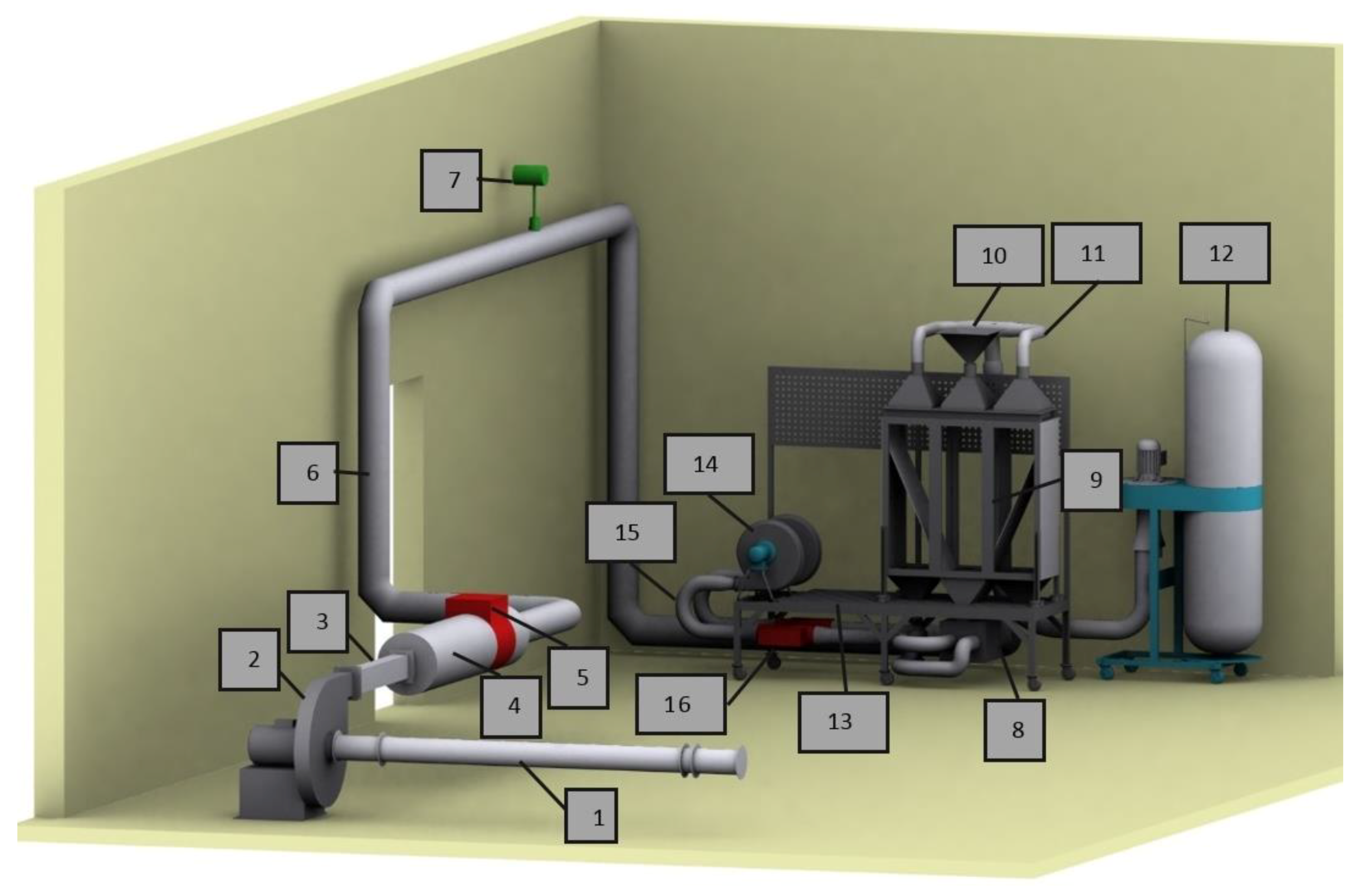
The adopted structural and technological solutions and the technological scheme of the installation are presented in
Figure 3 and
Figure 4.
Figure 3 shows that the system is marked. The following are indicated: fan suction pipeline (1), supply fan (2), discharge pipeline and rectangular cross-section (3), circular discharge pipeline (4), electric heaters (5), circular discharge pipeline SPIRO (6), flow meter Vortek (7), expansion box (8), fluidized bed drying chamber (9), raw coal storage tank (10), dry coal removal pipeline (11), dust extraction with bag filter (12), supporting structure of drying chamber (13), supply fan WN-1, WN-2 (14), pressure pipe (15), electric heater Nel-1, and Nel-2 (16).
The frame of the structure is made of closed profiles made of stainless steel. The walls of the chamber are made of transparent Plexiglas panels. The drying chamber consists of three sections connected together, 350 × 350 × 1000 mm in size. The whole installation was placed on a mobile platform made of steel construction.
The installation is equipped with a control and regulation system, which consists of modules from National Instrument’s C-Series. Moreover,
Advantech data acquisition modules from the ADAM-4000 series and converters for data transmission from measuring systems (RS485/USB and RS232C/USB) were used. In the experimental installation, sensors of quantities such as temperature, pressure, moisture content, and gas volume flow were installed, as well as the measurement of the electrical energy consumption of the devices. In
Figure 4b, an ideological diagram of the measurement system within the dryer chamber is shown.
The data system acquisition and control significantly simplifies the installation operation. It allows, among other things, to define the preset temperature of the drying process.
Figure 5a,b shows exemplary results of pressure and temperature distribution measurements in a fluidized bed chamber, archived and generated by the AKPiA system (Control and Measurement Instruments and Automation).
The temperatures over time and at different altitudes are shown in
Figure 5b. The inlet temperature, in this case, is 35 °C. The temperature change at different altitudes is shown. In
Figure 6, the temperature in time at different altitudes of the bed is shown, measured with seven temperature sensors (T 1-7) according to
Figure 5b.
3. Research Program
The main aim of the research was to determine the influence of factors like the type of coal, grain size, drying temperature, type of dryer, and drying time on the final moisture content of coal. Experimental studies were conducted in the laboratory of the Institute of Power Plants and Measurement Systems of the Opole University of Technology.
The research was carried out at a constant speed of drying airflow, which for 2D and 3D dryers was 10 m/s. This allowed obtaining the velocity of solid-phase particles of 0–8 mm grain size at the level of 1.5–5 m/s. The capacity of dried lignite portions was 0.9 dm3 for 2D installations and 12 dm3 for 3D installations. The bulk density of brown coal was 700–800 kg/m3. Constant microclimatic conditions were maintained in the room by ensuring a constant temperature and moisture content in the air.
Coal samples used for testing came from the lignite transport installation of the Turów and Bełchatów power plants, which were taken for crushers. Then, the coal was sieved to obtain a repeatable grain distribution of the tested coal samples.
The studies were carried out for two chamber geometries, which allowed for a better understanding of the fluidization phenomenon and brown coal drying process. The results obtained from both chambers will significantly facilitate advanced numerical analyses and calibrations of the existing chambers or the creation of original mathematical models. The obtained results will also be the basis for designing fluidized bed dryers on an industrial scale.
4. Methods
The change in the moisture content and the moisture loss from coal were continuously determined by the method of balancing the moisture content for air at the boundary of a fluidized apparatus (
Figure 7). In order to obtain high accuracy of the analysis results, the moisture content of the coal sample before and after each test was additionally determined by the thermogravimetric method.
Thermokinetics and the course of the drying process are determined using the momentary values of the changing mass of coal. To determine the values, a system was used to measure temperature, moisture content, and air pressure at the inlet and outlet of the dryer. The increase in the moisture content Δw (g/kg) in the air corresponds to the moisture content of evaporated brown coal water, Δw = Δw’. The relationships occurring in the dryer chamber are presented in the balance sheet diagram (
Figure 7).
The pressure of saturated vapor as a function of temperature was determined from (EN ISO 13788:2001):
One of the main problems affecting the accuracy of the obtained results is the time-varying input data, such as climatic data and temperature-dependent material properties [
41]. For practical purposes, we propose a solution in which publicly available standards are used to design the equipment. We balance the air before heating, which results from the local climate. For this purpose, appropriate temperatures are adopted for calculations, which in turn are dictated by standards, and therefore the two above formulas are used, which help more accurately calculate the saturated vapor pressure at the contact surface of the material with air [
42]. Further, they are also successfully used air conditioning and ventilation [
43].
On this basis, the moisture content in the air was determined to take into account the measured relative humidity [
44]:
where:
ϕ is the relative humidity of the air,
p is the approximate atmospheric pressure of the humid air,
psat is the saturation pressure of the water vapor.
Next, the change of relative humidity, Δw, expressed in g/kg of dry air corresponded to the moisture loss from the relation:
where: 1, 2 are indexes of air parameters measured before and after the dryer, respectively.
Drying thermokinetics is presented by determining the so-called drying curve (
Figure 8). It describes the loss of moisture in the dried material as a function of time. The shape of the curve depends mainly on the characteristics of moisture-binding, i.e., physicochemical properties of the dried material and the heat and mass movement between the solid and gas phase. In the initial period (AB section), the material is heated, then a linear dependence of moisture loss on time (BC section) occurs. After this period, the straight line turns into a curve approaching equilibrium moisture content Xr (%). Each of these periods is characterized by a different course of drying speed (
Figure 8b).
5. Results and Discussion
Selected test results are shown in
Figure 9,
Figure 10,
Figure 11,
Figure 12,
Figure 13,
Figure 14,
Figure 15,
Figure 16,
Figure 17,
Figure 18,
Figure 19 and
Figure 20.
Figure 9 and
Figure 10 show the influence of grain size and temperature on the drying process for both coal types. In the case of coal from Turów, the course in the examined period of time is linear for all grain sizes. In the case of coal from Bełchatów, in the first period of time, one notices the established drying conditions, yet in the next phase of drying, after about 10 min, the accelerated moisture reception takes place. In this case, the process is faster with smaller coal granulation, which can be seen in
Figure 9, where the decrease in moisture content for grain size from the range 0.4–2 mm after 19 min of drying is 9%, while for grains larger than 6.3 mm it is 7%.
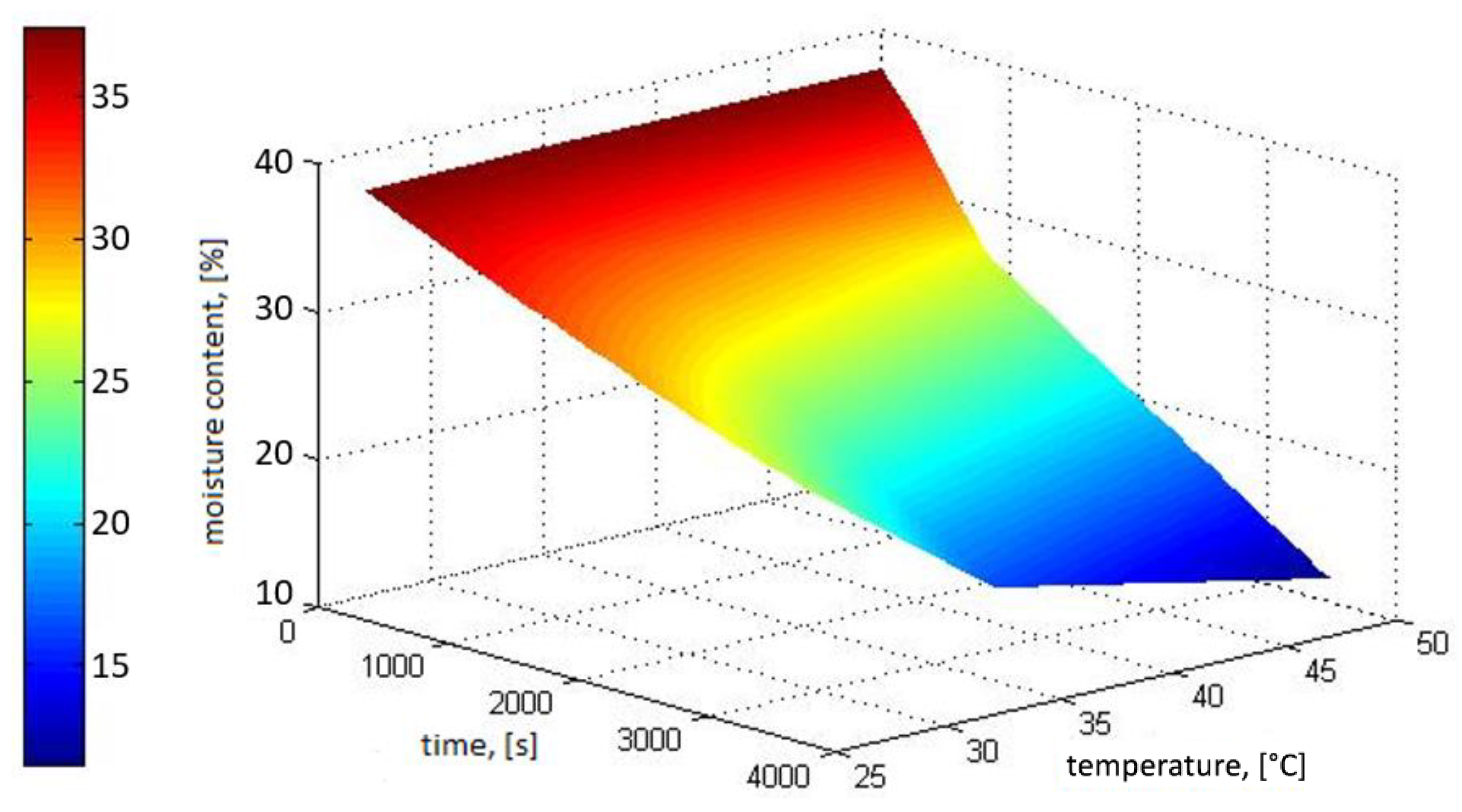
Figure 11 and
Figure 12 shows the time course of changes in the moisture content of coal in the 3D installation at different air temperatures. Assuming a uniform distribution of moisture content in the volume of the coal sample tested and water content on the surface of particles during the tests, the drying process is carried out at a constant speed at temperatures of 27–35 °C. During the drying process at higher temperatures (50–70 °C), the shape of the function becomes similar to the literature values (
Figure 8). This clearly shows the heating phase of the material and the asymptotic convergence to the maximum moisture content of the coal, called equilibrium.
The comparison of the course of moisture removal from both investigated coals in different dryer geometries (2D and 3D) and in different drying temperatures is presented in
Figure 13 and
Figure 14. The presented results show that lower moisture content of coal was obtained in the 3D installation. After an hour, the difference is about 5% for coal from Bełchatów and 9% for coal from Turów, respectively. Better drying efficiency in the 3D installation results from the fact that in the volume of the fluidized bed chamber a better and more homogeneous distribution of coal fraction density in the air was obtained in the whole volume of the fluidized bed chamber.
In order to organize the results obtained during various tests, the measurement data were approximated to the function of two variables: drying time and temperature. The result of such analysis allowed us to generate an equation of continuous surface function in the time interval t = 0.3600 s and temperature T = 27 ÷ 70 °C. The obtained form of the regression equation is a polynomial function:
The quality of matching the function to the measurement data is confirmed by the obtained quality assessment coefficients. Thus, the determination coefficient R2 and the corrected determination coefficient R2 of equations reached values above 0.97.
6. Conclusions
Lignite has highly differentiated properties depending on many factors, especially depending on its origin. This article discusses the drying properties of coal from two mines located in Bełchatów and Turów, Poland. The two coal types had significantly different physical and chemical properties. Moreover, this paper discusses the process of drying in a newly designed dryer, where we used a low-temperature heat source from the temperature range 27–70 °C with high energy efficiency in comparison to solutions available on the market.
This paper presents the results of laboratory tests in the field of assessing the usefulness of a fountain type (jet spouted) and bubbling fluidized bed for brown coal drying. The results obtained for two different geometries of dryer chambers were analyzed and the results were compared with each other. An important result of the research is an increase in the efficiency of coal moisture collection with an increase in the chamber volume. High effectiveness of the fountain-bubble method in drying brown coal using a low-temperature heating medium (up to 50 °C) was also confirmed. The necessity of ensuring the essential technological parameters has been pointed out thanks to the drying process, which can be conducted intensively and with a small amount of energy consumption.
The research showed a significant influence of time and temperature on the coal drying process. With the increase in drying time and temperature, the moisture content in coal decreased, causing a decrease in the mass of dried coal particles, which consequently led to a decrease in the hydraulic resistance of the fountain and bubble bed layer.
The performance of numerous laboratory tests allowed the development of test results in the form of two variables, taking into account the two most important parameters of the drying process, i.e., temperature and time. The functions determined in this way can be used, among other things, to quickly estimate the speed and efficiency of coal drying. In addition, the results can be used to design installations on a larger technical scale.
The main reason for the difference in the moisture removal rate for brown coal from Bełchatów and Turów in similar thermal and flow conditions is the difference in the surface moisture content of coal. Differences in drying speed may also be caused by different content of mineral parts in the fuel and their different structure. The high ash content of lignite usually results in a greater loss of moisture during the drying process. Bełchatów coal has 19.08% of ash and Turów coal 16.62%, respectively.
A novelty in this article is the attempt to use low-temperature heat regardless of its origin. Another novelty is the development of a structural solution of the dryer for these conditions, for which an analysis of thermokinetics of the coal drying process is needed. Moreover, we present a novel analysis of a specific type of coal for the drying process, which has not been published thus far.
Author Contributions
Conceptualization, methodology, writing—original draft preparation, Z.P.; resources, software, data curation, investigation, K.R. and P.S.; validation, formal analysis, A.D.; Supervision, writing—review and editing, visualization, S.A. All authors have read and agreed to the published version of the manuscript.
Funding
This research received no external funding.
Conflicts of Interest
The authors declare no conflict of interest.
References
- Tańczuk, M.; Radziewicz, W.; Olszewski, E.; Skorek, J. Projected configuration of a coal-fired district heating source on the basis of comparative technical-economical optimization analysis. In E3S Web of Conferences; EDP Sciences: Les Ulis, France, 2017; Volume 19, p. 01007. [Google Scholar]
- Yan, M.; Ma, C.; Shen, Q.; Song, Z.; Chang, J. A novel lignite pre-drying system integrated with flue gas waste heat recovery at lignite-fired power plants. Appl. Therm. Eng. 2019, 150, 200–209. [Google Scholar] [CrossRef]
- Liu, M.; Qin, Y.; Yan, H.; Han, X.; Chong, D. Energy and water conservation at lignite-fired power plants using drying and water recovery technologies. Energy Convers. Manag. 2015, 105, 118–126. [Google Scholar] [CrossRef]
- Gładysz, P.; Ziębik, A. Thermo-ecological evaluation of advanced coal-fired power technologies. In Green Energy and Technology; Springer: Cham, Switzerland, 2017; pp. 443–471. [Google Scholar] [CrossRef]
- Liu, M.; Xu, C.; Han, X.; Liu, R.; Qin, Y.; Yan, J. Integration of evaporative dryers into lignite-fired power plants: A review. Dry. Technol. 2019, 1–19. [Google Scholar] [CrossRef]
- Ma, Y.; Yuan, Y.; Jin, J.; Zhang, H.; Hu, X.; Shi, D. An environment friendly and efficient lignite-fired power generation process based on a boiler with an open pulverizing system and the recovery of water from mill-exhaust. Energy 2013, 59, 105–115. [Google Scholar] [CrossRef]
- Wang, W.C. Laboratory investigation of drying process of Illinois coals. Powder Technol. 2012, 225, 72–85. [Google Scholar] [CrossRef]
- Liu, M.; Yan, J.J.; Chong, D.T.; Liu, J.P.; Wang, J.S. Thermodynamic analysis of pre-drying methods for pre-dried lignite-fired power plant. Energy 2013, 59, 105–115. [Google Scholar] [CrossRef]
- Agraniotis, M.; Koumanakos, A.; Doukelis, A.; Karellas, S.; Kakaras, E. Investigation of technical and economic aspects of pre-dried lignite utilisation in a modern lignite power plant towards zero CO2 emissions. Energy 2012, 45, 134–141. [Google Scholar] [CrossRef]
- Allardice, D.J.; Clemow, L.M.; Favas, G.; Jackson, W.R.; Marshall, M.; Sakurovs, R. The characterisation of different forms of water in low rank coals and some hydrothermally dried products. Fuel 2003, 82, 661–667. [Google Scholar] [CrossRef]
- Rao, Z.; Zhao, Y.; Huang, C.; Duan, C.; He, J. Recent developments in drying and dewatering for low rank coals. Prog. Energy Combust. Sci. 2015, 46, 1–11. [Google Scholar] [CrossRef]
- Yin, Y.; Li, C.; Liao, J.J.; Mo, Q.; Chang, L.P.; Bao, W.R. Research progress of lignite upgrading and its physical and chemical structure evolvement. Xiandai Huagong Modern Chem. Ind. 2017, 37, 56–59 and 61. [Google Scholar] [CrossRef]
- Komatsu, Y.; Sciazko, A.; Zakrzewski, M.; Akiyama, T.; Hashimoto, A.; Shikazono, N.; Kaneko, S.; Kimijima, S.; Szmyd, J.S.; Kobayashi, Y. Towards the improvement of thermal efficiency in lignite-fired power generation: Concerning the utilization of Polish lignite deposits in state-of-the-art IGCC technology. Int. J. Energy Res. 2016, 40, 1757–1772. [Google Scholar] [CrossRef]
- Nikolopoulos, N.; Violidakis, I.; Karampinis, E.; Agraniotis, M.; Bergins, C.; Grammelis, P.; Kakaras, E. Report on comparison among current industrial scale lignite drying technologies (A critical review of current technologies). Fuel 2015, 155, 86–114. [Google Scholar] [CrossRef] [Green Version]
- Pawlak-Kruczek, H.; Lichota, J.; Plutecki, Z. Efficiency of brown coal dryer depending on drying method. Rynek Energii 2011, 2011, 150–158. [Google Scholar]
- Xu, C.; Xu, G.; Yang, Y.; Zhao, S.; Zhang, K.; Zhang, D. An improved configuration of low-temperature pre-drying using waste heat integrated in an air-cooled lignite fired power plant. Appl. Therm. Eng. 2015, 90, 312–321. [Google Scholar] [CrossRef]
- Pawlak-Kruczek, H.; Niedźwiecki, Ł.; Ostrycharczyk, M.; Czerep, M.; Plutecki, Z. Potential and methods for increasing the flexibility and efficiency of the lignite fired power unit, using integrated lignite drying. Energy 2019, 181, 1142–1151. [Google Scholar] [CrossRef]
- Klimenda, F.; Soukup, J.; Skočilasová, B.; Koutný, R. Efficiency of fuel drying to increase heat production. In Proceedings of the AIP Conference, Cesme-Izmir, Turkey, 26–30 May 2019. [Google Scholar]
- Jaszczur, M.; Dudek, M.; Rosen, M.A.; Kolenda, Z. An analysis of integration of a power plant with a lignite superheated steam drying unit. J. Clean. Prod. 2020, 243, 118635. [Google Scholar] [CrossRef]
- Xin, F.W.; Xu, Z.Q.; Tu, Y.N.; Yang, W.; Han, X.Y.; Geng, P.F. Dehydration and Upgrading of Lignite with Microwave. Applied Mechanics and Materials 2013, Volume 423–426, 667–673. [Google Scholar] [CrossRef]
- Xiaoyang, D. New progress of coal preparation technology in China. In Proceedings of the XVIII International Coal Preparation Congress, Saint-Petersburg, Russia, 28 June–1 July 2016; ISBN 9783319409436. [Google Scholar]
- Zhang, K.; You, C. Numerical simulation of lignite drying in a packed moving bed dryer. Fuel Process. Technol. 2013, 110, 122–132. [Google Scholar] [CrossRef]
- Pawlak-Kruczek, H.; Plutecki, Z.; Michalski, M. Brown Coal Drying in a Fluidized Bed Applying a Low-Temperature Gaseous Medium. Dry. Technol. 2014, 32, 1334–1342. [Google Scholar] [CrossRef]
- Tanczuk, M.; Masiukiewicz, M.; Anweiler, S.; Junga, R. Technical aspects and energy effects of waste heat recovery from district heating boiler slag. Energies 2018, 11, 796. [Google Scholar] [CrossRef] [Green Version]
- Puadian, N.; Li, J.; Pang, S. Analysis of operation parameters in a dual fluidized bed biomass gasifier integrated with a biomass rotary dryer: Development and application of a system model. Energies 2014, 7, 4342–4363. [Google Scholar] [CrossRef] [Green Version]
- Tańczuk, M.; Kostowski, W.; Karaś, M. Applying waste heat recovery system in a sewage sludge dryer—A technical and economic optimization. Energy Convers. Manag. 2016, 125, 121–132. [Google Scholar] [CrossRef]
- Klutz, V.H.J.; Kloecker, K.J.; Lambertz, J. Das WTA-Verfahren als Vortrocknungsstufe fuer moderne Kraftwerkskonzepte auf Basis Braunkohle. VGB Kraftw. 1996, 76, 1–7. [Google Scholar]
- Karthikeyan, M.; Zhonghua, W.; Mujumdar, A.S. Low-rank coal drying technologies - Current status and new developments. Dry. Technol. 2009, 27, 403–415. [Google Scholar] [CrossRef]
- Unsworth, J.F.; Fowler, C.S.; Heard, N.A.; Weldon, V.L.; McBrierty, V.J. Moisture in coal. 1. Differentiation between forms of moisture by n.m.r. and microwave attenuation techniques. Fuel 1988, 67, 1111–1119. [Google Scholar] [CrossRef]
- Kmieć, A.; Englart, S.; Ludwińska, A. Teoria i technika fluidyzacji. Pr. Nauk. Inst. Inz. Chr. Sr. Politech. Wroc. 2007, 83, 108. [Google Scholar]
- Saidi, M.; Basirat Tabrizi, H.; Grace, J.R. A review on pulsed flow in gas-solid fluidized beds and spouted beds: Recent work and future outlook. Adv. Powder Technol. 2019, 30, 1121–1130. [Google Scholar] [CrossRef]
- Lim, M.T.; Pang, S.; Nijdam, J. Investigation of solids circulation in a cold model of a circulating fluidized bed. Powder Technol. 2012, 226, 57–67. [Google Scholar] [CrossRef]
- Krajačić, G.; Vujanović, M.; Duić, N.; Kılkış, Ş.; Rosen, M.A.; Ahmad Al-Nimr, M. Integrated approach for sustainable development of energy, water and environment systems. Energy Convers. Manag. 2018, 159, 398–412. [Google Scholar] [CrossRef]
- Calise, F.; Costa, M.; Wang, Q.; Zhang, X.; Duic, N. Recent advances in the analysis of sustainable energy systems. Energies 2018, 11, 2520. [Google Scholar] [CrossRef] [Green Version]
- Mendecka, B.; Lombardi, L.; Gładysz, P.; Stanek, W. Exergo-ecological assessment of waste to energy plants supported by solar energy. Energies 2018, 11, 773. [Google Scholar] [CrossRef] [Green Version]
- Atsonios, K.; Violidakis, I.; Agraniotis, M.; Grammelis, P.; Nikolopoulos, N.; Kakaras, E. Thermodynamic analysis and comparison of retrofitting pre-drying concepts at existing lignite power plants. Appl. Therm. Eng. 2015, 74, 165–173. [Google Scholar] [CrossRef] [Green Version]
- Li, Y.; Zhao, H.; Song, Q.; Wang, X.; Shu, X. Influence of critical moisture content in lignite dried by two methods on its physicochemical properties during oxidation at low temperature. Fuel 2018, 221, 27–37. [Google Scholar] [CrossRef]
- Anweiler, S.; Masiukiewicz, M. Application of stereology for two-phase flow structure validation in fluidized bed reactors. Therm. Sci. 2016, 20. [Google Scholar] [CrossRef] [Green Version]
- Lichota, J.; Plutecki, Z. Coal drying in power plants. Rynek Energii 2007, 6, 36–41. [Google Scholar]
- Plutecki, Z. Requirements for energy efficiency as a chance to increase the effectiveness of insulation systems [Wymagania w zakresie efektywności energetycznej szansä... na wzrost skuteczności UKładów termoizolacyjnych]. Rynek Energii 2016, 124, 57–64. [Google Scholar]
- Leśniak, B.; Słupik, Ł.; Jakubina, G. The determination of the specific heat capacity of coal based on literature data. Chemik 2013, 67, 560–571. [Google Scholar]
- Ramos, N.M.; Delgado, J.Q.; Barreira, E.; De Freitas, V.P. Hygrothermal properties applied in numerical simulation: Interstitial condensation analysis. J. Build. Apprais. 2009, 5, 161–170. [Google Scholar] [CrossRef]
- Goodfellow, H. Industrial Ventilation Design Guidebook; Academic Press: Cambridge, MA, USA, 2001. [Google Scholar]
- Rao, Y.V.C. Introduction to Thermodynamics [Books and Reports]. IEEE Power Eng. Rev. 2005, 15, 32. [Google Scholar] [CrossRef]
- Bednarczyk Jerzy Prospective strategies of technology of energetic utilization of brown coal in conditions of great limitation of carbon dioxide emission. Górnictwo Odkryw. 2007, 5–7, 25–34.
Figure 1.
Location of the Bełchatów and Turów power plants on the Polish map.
Figure 1.
Location of the Bełchatów and Turów power plants on the Polish map.
Figure 2.
Two-dimensional (2D) test installation: (a) dimensional drawing; (b) view.
Figure 2.
Two-dimensional (2D) test installation: (a) dimensional drawing; (b) view.
Figure 3.
Visualization of the technological system of the three-dimensional (3D) installation.
Figure 3.
Visualization of the technological system of the three-dimensional (3D) installation.
Figure 4.
Schematic diagram of the technological system (a) and measurand in the apparatus (b).
Figure 4.
Schematic diagram of the technological system (a) and measurand in the apparatus (b).
Figure 5.
Sample test results for 3D installation filled with Bełchatów brown coal, grain size 0–8 mm: (a) air pressure during the coal drying process; (b) the distribution of the air temperature in the fluidization chamber during the coal drying process.
Figure 5.
Sample test results for 3D installation filled with Bełchatów brown coal, grain size 0–8 mm: (a) air pressure during the coal drying process; (b) the distribution of the air temperature in the fluidization chamber during the coal drying process.
Figure 6.
Sample chart of temperature in time at different levels of the bed, measured with seven temperature sensors (T 1-7) according to
Figure 5b.
Figure 6.
Sample chart of temperature in time at different levels of the bed, measured with seven temperature sensors (T 1-7) according to
Figure 5b.
Figure 7.
Moisture balance in the dryer compartment.
Figure 7.
Moisture balance in the dryer compartment.
Figure 8.
Curves characterizing the drying process: (
a) drying curve; (
b) drying speed curve [
45].
Figure 8.
Curves characterizing the drying process: (
a) drying curve; (
b) drying speed curve [
45].
Figure 9.
Effect of lignite grain size on the drying process at 35 °C for Bełchatów lignite.
Figure 9.
Effect of lignite grain size on the drying process at 35 °C for Bełchatów lignite.
Figure 10.
Effect of lignite grain size on the drying process at 35 °C for Turów lignite.
Figure 10.
Effect of lignite grain size on the drying process at 35 °C for Turów lignite.
Figure 11.
Influence of air temperature on the drying process in the 3D installation. Grain size was 0–8 mm of Bełchatów lignite.
Figure 11.
Influence of air temperature on the drying process in the 3D installation. Grain size was 0–8 mm of Bełchatów lignite.
Figure 12.
Influence of air temperature on the drying process in the 3D installation. Grain size was 0–8 mm of Turów lignite.
Figure 12.
Influence of air temperature on the drying process in the 3D installation. Grain size was 0–8 mm of Turów lignite.
Figure 13.
Influence of chamber geometry on coal drying process. The grain size was 0–8 mm, temperature 27 °C, Bełchatów coal.
Figure 13.
Influence of chamber geometry on coal drying process. The grain size was 0–8 mm, temperature 27 °C, Bełchatów coal.
Figure 14.
Influence of chamber geometry on the coal drying process. The grain size was 0–8 mm, temperature 27 °C, Turów coal.
Figure 14.
Influence of chamber geometry on the coal drying process. The grain size was 0–8 mm, temperature 27 °C, Turów coal.
Figure 15.
Plane diagram of the drying process, 2D installation; Bełchatów; 0–8 mm, temperature: 27–50 °C.
Figure 15.
Plane diagram of the drying process, 2D installation; Bełchatów; 0–8 mm, temperature: 27–50 °C.
Figure 16.
Plane diagram of the drying process, 2D installation; Turów; 0-8 mm; temperature: 27–50 °C.
Figure 16.
Plane diagram of the drying process, 2D installation; Turów; 0-8 mm; temperature: 27–50 °C.
Figure 17.
Comparative study of the influence of drying air temperature and time on the moisture content of coal (%), 2D installation; 0-8 mm, temperature 27–50 °C for: (a) Bełchatów; (b) Turów.
Figure 17.
Comparative study of the influence of drying air temperature and time on the moisture content of coal (%), 2D installation; 0-8 mm, temperature 27–50 °C for: (a) Bełchatów; (b) Turów.
Figure 18.
Plane diagram of the drying process, 3D installation; Bełchatów; 0–8 mm; temperature 27–50 °C.
Figure 18.
Plane diagram of the drying process, 3D installation; Bełchatów; 0–8 mm; temperature 27–50 °C.
Figure 19.
Plane diagram of the drying process, 3D installation; Turów; 0–8 mm; temperature 27–50 °C.
Figure 19.
Plane diagram of the drying process, 3D installation; Turów; 0–8 mm; temperature 27–50 °C.
Figure 20.
Comparative study of the influence of drying air temperature and time on the moisture content of coal (%), 3D installation; 0–8 mm; temperature 27–50° C for: (a) Bełchatów; (b) Turów.
Figure 20.
Comparative study of the influence of drying air temperature and time on the moisture content of coal (%), 3D installation; 0–8 mm; temperature 27–50° C for: (a) Bełchatów; (b) Turów.
Table 1.
Characteristics of the lignite under investigation.
Table 1.
Characteristics of the lignite under investigation.
| Source of the Lignite | Carbon Mass Share | Hydrogen Mass Share | Nitrogen Mass Share | Sulphur Mass Share | Oxygen Mass Share | Ash Mass Share | Combustion Heat | MoistUre |
|---|
| Turów | 58.88 | 4.47 | 0.45 | 0.19 | 29.30 | 6.71 | 22621 | 42.78 |
| Bełchatów | 50.98 | 3.39 | 0.68 | 0.24 | 25.23 | 19.47 | 20022 | 54.00 |
© 2020 by the authors. Licensee MDPI, Basel, Switzerland. This article is an open access article distributed under the terms and conditions of the Creative Commons Attribution (CC BY) license (http://creativecommons.org/licenses/by/4.0/).


