Abstract
The unbalanced distribution of resource and consuming centers in China has prompted the AC/DC hybrid transmission technology. The maintenance scheduling of an AC/DC hybrid transmission network is the key technology to ensure its safety and reliability. In this study, the mutual influence mechanism of an AC/DC system in a maintenance period was analyzed in detail. The overhead transmission line and transformer are key equipment within an AC/DC hybrid transmission network, and an optimization model of the key equipment maintenance scheduling was established. The objective of the model was to improve the system reliability during the maintenance scheduling. By considering the constraints of maintenance cost, maintenance resources, and maintenance workload, the maintenance scheduling of overhead transmission lines and transformer branches was obtained. The over-limit situation of power flow and the weakness of the system during the maintenance period was evaluated. The “double-layer substitution method” was adopted to convert the nonlinear constraints into its bilinear formulation such that it could then be solved. The random number sampling method was used to quantify the system reliability, and the commercial optimization software was used to solve the optimized scheduling. Based on the improved IEEE RTS-79 system and the Hubei Province electrical system, the simulation results showed the effectiveness of the proposed method.
1. Introduction
China is a country with a vast territory. Its energy supply and load demand are in a state of unbalanced distribution. In recent years, in order to solve this problem, China has rapidly developed ultra-high voltage direct current (UHVDC) transmission technology, which has the advantages of large transmission capacity, high efficiency, and high transmission reliability. The technology is widely used in long-distance and large-area grid interconnections [1]. With the rapid development of the national economy, the power demand is increasing. The State Grid Corporation of China has vigorously promoted the construction of UHVDC power transmission in order to complete the large-capacity dispatching of power. During 13th Five-Year Plan period, 11 UHVDC transmission lines will be built. The formation of synchronous grids in the east and west will be accelerated and communication channels for the northeast and north, central, and eastern China power grids will be established [2]. With the full implementation of the 13th Five-Year Plan, the AC/DC hybrid transmission grid has played an important role in the development of future power systems. However, the distribution of power flow in AC/DC hybrid transmission grids is more complicated, and problems, such as power shortages or power flow off-limit caused by breaks, are more serious [3]. Therefore, higher requirements are imposed on the maintenance scheduling of the AC/DC hybrid transmission network.
At present, there is a large literature on the optimization of power grid maintenance scheduling: Xu et al. [4] established a two-tier optimization model of the distribution network maintenance scheduling. The model took the number of switching actions and the line loss as the optimization parameters. A particle swarm optimization and a heuristic loads transfer algorithm were used to obtain the optimal maintenance scheduling. Wen et al. [5] took the expected energy that was not supplied and the cost of maintenance as optimization parameters. A niche multi-objective particle swarm algorithm was used to obtain optimized maintenance scheduling of the power grid. Wei et al. [6] proposed an overall maintenance strategy of the transmission system based on equal risk. The load shedding amount in each period was leveled to achieve the goal of optimizing maintenance. Xu et al. [7] considered the uncertain factors in the maintenance process of the transmission system. The Monte Carlo algorithm was used to calculate the expected energy that was not supplied during the maintenance period, and then the maintenance risk of the power grid was quantified. After that, a two-level model was established to obtain the optimal maintenance scheduling. Wei et al. [8] considered the impact of the load transfer path on the system risk during the maintenance period. A search tree was used to obtain the load transfer path. Using an objective function to find the minimum comprehensive risk cost, the risk during the maintenance period was reduced by optimizing the load transfer path. Rao et al. [9] proposed a harmonious search algorithm to solve the distribution network reconfiguration problem. The gradient search algorithm was replaced with a random search algorithm to eliminate the need for derived information. Xian et al. [10] introduced intelligent algorithms to the maintenance scheduling optimization problem. Furthermore, an immune-taboo hybrid intelligent algorithm, genetic-simulated annealing, and other algorithms were adopted to solve the maintenance scheduling optimization problem. Teng and Fang [11] introduced a game theory method to the optimization of the maintenance for a distribution network. The method took the equipment layer and the main body of the network as game participants, and used the number of maintenance equipment, the maintenance scheduling, and the maintenance equipment as the game to solve the contradiction between the equipment state and maintenance scheduling. Er et al. [12] established a model of the equipment condition evaluation and grid loss risk calculation that considered the power shortage, load importance, equipment value, and maintenance of the distribution network under normal or maintenance conditions. The model was used to solve the problem of distribution network maintenance scheduling, which ignored equipment differences and the real-time state.
The above studies are very enlightening, but there are two problems, as follows: (1) These studies have mainly concentrated on the distribution network side, there is a lack of research on the interaction mechanism between AC and DC transmission systems during the maintenance period, and they fail to consider the impact of DC system breaks on the power shortage and flow off-limit of AC systems. (2) The optimization models of the maintenance scheduling that were established in the above studies all contained complex nonlinear constraints and the solution depended on intelligent algorithms. Intelligent algorithms have slow solutions and require many iterations that may not necessarily converge. Furthermore, the result obtained by each calculation may not be the same [13]. In contrast, mixed integer linear programming has the advantages of fast speed, less calculation time, and provides a single optimization result [14,15].
In order to simulate the state of transmission lines, the methods of state sampling and the relationship between Monte Carlo simulation and sampling from Markov processes has been widely studied. Xu et al. [7] used standard normal distribution random numbers to simulate the state of transmission lines and their load. Huang et al. [16] introduced the method of Latin hypercube sampling to probabilistic load flow calculations. Each input random variable was sampled to ensure that the random distribution area could be completely covered by the sampling points. Huang et al. [17] evaluated the reliability of a distributed integrated energy system based on Markov chain Monte Carlo (MCMC) simulations. Wang et al. [18] established the model for the fast analysis of power system operation reliability. Xiao et al. [19] evaluated the reliability of a photovoltaic power station based on the Markov chain Monte Carlo method. According to above studies, a high calculation accuracy can be obtained via the Markov chain Monte Carlo method when the sample size is large enough. In a situation where the requirements for accuracy are not very high, using a random number standard normal distribution to simulate the state of the transmission lines is a simple and feasible method, for example in Xu et al. [7]. The sample size of this paper is small and random number sampling could have a high sampling efficiency such that the states of the transmission lines could be obtained efficiently.
In view of the above problems, this paper studies the optimization model of the key equipment maintenance scheduling for AC/DC hybrid transmission grids based on mixed integer linear programming. This paper is organized as follows. In Section 2, the interaction mechanism between AC and DC hybrid transmission systems, the optimization goal, and the constraints of the model are presented. In Section 3, the “double-layer replacement method” is used to linearize the non-linear constraints, such as maintenance resources. Section 4 provides the case study of an improved IEEE reliability test 79 system for key equipment maintenance scheduling of an AC/DC hybrid transmission network and the simulation results are presented to verify the effectiveness of the proposed maintenance scheduling.
2. Optimization Model of the Key Equipment Maintenance Scheduling
In this section, the impact of a non-maintenance line’s outage probability and operating state on grid reliability is considered first. The model uses the equipment health index to calculate the outage probability of non-maintenance lines and the random number sampling is used to simulate the operation state of non-maintenance lines. Then, the expected energy that is not supplied is used as the model optimization parameter to quantify the reliability of the power grid during the maintenance period. Finally, overhead transmission line maintenance scheduling u, transformer maintenance scheduling x, and maintenance resource arrangement scheduling z are used as decision variables to establish the AC/DC hybrid transmission network maintenance scheduling optimization model.
2.1. Outage Probability of Non-Maintenance Lines
As an important indicator of equipment reliability, the probability of outage is closely related to the health index of the equipment. It is generally believed that the relationship between the probability of outage of the equipment and the health index is as follows [20],
where is the outage probability of non-maintenance lines, K is the scale factor, C is the coefficient of curvature, and H is the health index.
In this paper, the health index H is used to calculate the outage probability of the equipment under long-term operating conditions. The health index is positively related to the equipment state. We refer to the composition and evaluation standards of state quantities in the Q/GDW173-2008 “Guidelines for the Evaluation of the State of Overhead Transmission Lines,” which is issued by the State Grid Corporation of China. The state of each component for the transmission lines can be obtained through tours, live detection, routine tests, sampling tests, and other means. The state weights are divided such that they consider the influence of each state on the safe operation of the line. The points are comprehensively deducted to obtain the state score of each component for the overhead transmission line. In this paper, the state score is directly equivalent to the health index. According to this guideline, the lower limit of H is about 50 (different devices vary depending on the composition of the state quantity), and the upper limit of the value is 100 [21].
Due to the difficulty in obtaining the actual outage probability of the equipment, this calculation refers to the “Hubei Province Transmission Equipment State Evaluation Report” to determine the health index of overhead transmission lines and transformers. The K and C values of transformers and overhead transmission lines are obtained, which refer to the health index quantification method of the distribution network risks in Chang et al. [21] and combine with the power transmission equipment reliability law [22]. Then, the relationship between the outage probability and health index is as follows.
(1) The relationship between the transformer outage probability and health index is:
(2) The relationship between the outage probability of overhead transmission lines and the health index is:
2.2. Simulation of a Non-Maintenance Line State
It is assumed that the generator output scheduling has been determined during the maintenance period of the AC/DC hybrid transmission grid. Uncertain factors, such as unit failure or mis-operation, are not considered. AC/DC hybrid grids can reduce frequent machine cutting due to the faults of DC transmission lines. However, the mutual influence of AC and DC transmission systems cannot be ignored. When some AC transmission lines are maintained, the reliability of the system is reduced. If the DC system fails at this time, it may cause a large-scale power flow transfer in the AC system and increase the AC system power flow off-limit. Therefore, the maintenance scheduling and system reliability of AC/DC hybrid transmission networks are directly affected by uncertain factors, such as breaks in non-maintenance lines and faults of DC transmission lines [7].
It is assumed that the state of the non-maintenance overhead transmission lines and the non-maintenance transformers can be sampled by a random number w, which follows a uniform distribution on [0, 1]. The expression is as follows [6]:
The lines near the access point of the DC transmission system cannot be maintained at the same time in order to prevent the voltage drop. It may cause a commutation failure of the DC transmission system, which can lead to faults in the DC transmission lines. Therefore, the transmission power of the DC transmission system is closely related to the state of the transmission lines near the DC access point. The specific form is as follows:
where Pn is the rated power of the DC transmission system, Pd is the actual power of the DC transmission system, and is the maintenance state of the transmission lines.
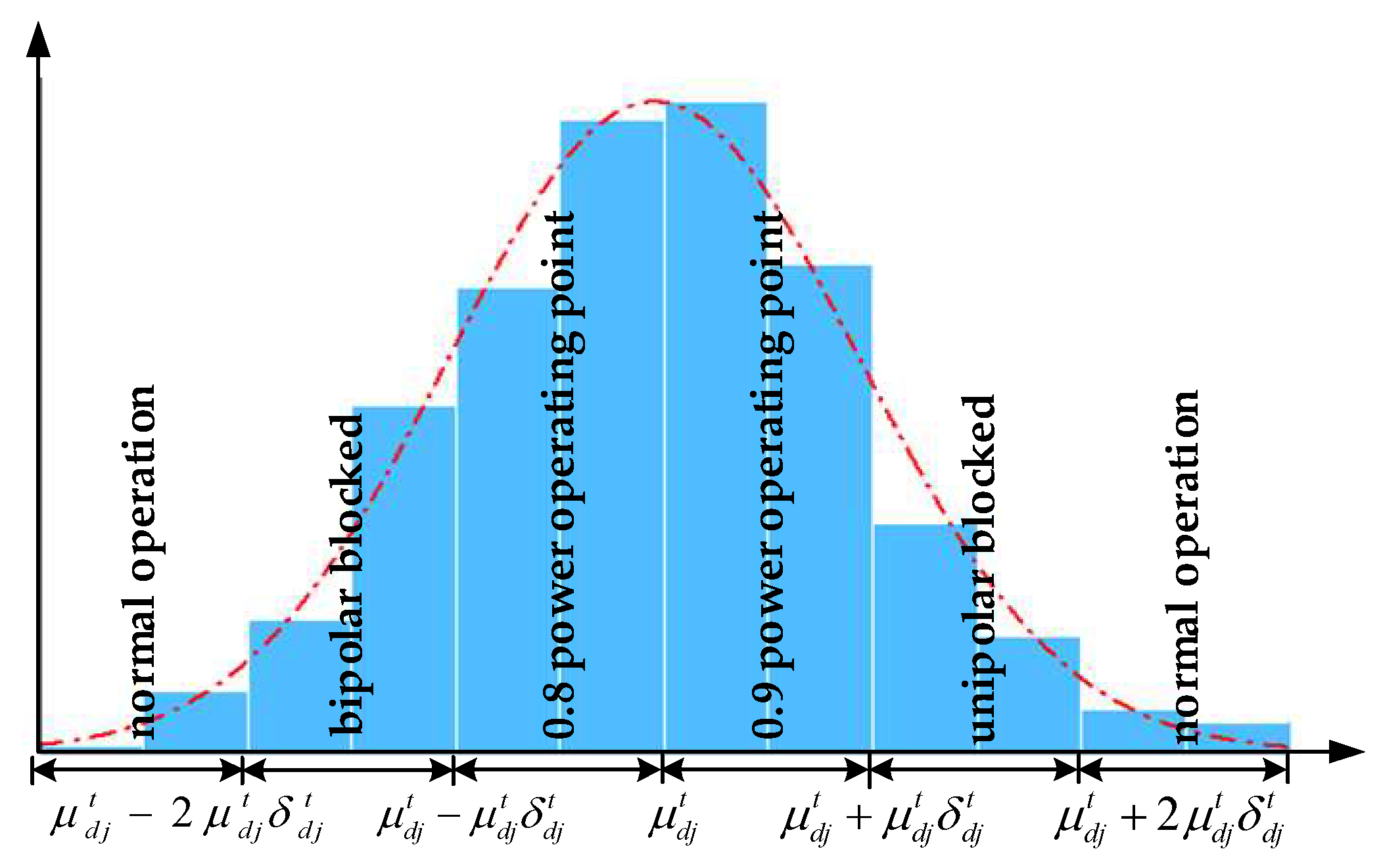
The transmission power of a DC system is also closely related to its own state. The break or unipolar failure of the DC transmission line may cause the bipolar or unipolar blocking of the DC transmission system, which results in a large-scale power shortage. In addition, DC transmission systems have different power operating points under normal conditions. Assume that the state of the DC transmission line j follows a normal distribution [7]. The sampling value during time t is as follows:
where is the standard normal random number. is the mathematical expectation. is the variance.
2.3. Goals of Optimization
Maintenance of AC/DC hybrid transmission grids generally may not result in direct load cutting, but the outage of some lines will reduce the reliability of the grid. This paper uses EENS (expected energy not supplied) to quantify the impact of maintenance scheduling on the operational reliability of transmission grids. The EENS is defined as the total amount of power loss for the AC/DC hybrid transmission grid line due to probable outages during the maintenance period. EENS is used to describe the decreasing degree of grid reliability caused by maintenance [22,23]. The functions describing EENS are as follows:
where and represent the expected energy caused by faults of non-maintenance lines and the planned energy caused by system maintenance, respectively. The decision variables are the maintenance scheduling of overhead transmission lines u, maintenance scheduling of transformers x, and maintenance resource scheduling z. T is the number of maintenance periods. St is the set of internal load states during the maintenance period. is the state of the non-maintenance lines, where represents the line being out of maintenance and represents the line being under maintenance. is the amount of load cutting due to the failure of non-maintenance lines. is the outage probability of non-maintenance lines. M is the total number of system lines. N is the total number of equipment to be maintained. is the planned energy due to the maintenance of key equipment. Tt is the number of hours per unit during the maintenance period.
2.4. Constraints
(1) Cost of maintenance
Costs will need to be met for the maintenance of lines. The main reason for the large differences in the cost of different scheduling is the additional maintenance cost resulting from maintenance during holidays [24]. Its expression is as follows:
where N is the total number of equipment to be maintained. is the cost per unit time of each team to maintain the line or the transformer. is the double pay for the consideration of the holiday maintenance. is the number of workers in the team arranged for the line or transformer in the tth period. is the maintenance state of the overhead transmission lines. is the maintenance state of the transformers. signifies the power outage maintenance of overhead transmission lines. signifies the normal operation of the transformers.
(2) Constraints of maintenance time
The maintenance of overhead transmission lines and transformers should be completed within a specified period [25]. Its expression is as follows:
where Lei and Lli are the earliest and latest time points for the overhead transmission maintenance, respectively. Tej and Tlj are the earliest and latest time points of the transformer maintenance.
(3) Constraints of continuous maintenance time
Maintenance should be continued until the workload is completed after the start. Furthermore, there should be no interruption during this maintenance [26]. The expression is as follows:
where Lsi and Tsj respectively indicate that the maintenance of the overhead transmission lines starts at the Lsi time point. Furthermore, the maintenance of transformers starts at the Tsj time point. Lbi and Tbj indicate the workload required for the maintenance of overhead transmission lines i and transformers j.
(4) Constraints on maintenance workload
The same line with different maintenance scheduling methods and different maintenance resources should require the same workload [27]. The decomposed expression is as follows:
(5) Constraint of mutually exclusive maintenance
Lines that will cause electrical islands should be staggered to avoid unnecessary power outages. Lines that will affect the voltage of the DC transmission access point should be maintained in time to prevent a DC power system commutation failure. Its expression is as follows:
where are the maintenance states of different lines at the same time.
(6) Constraints of maintenance resource
The maintenance resources, such as manpower and material resources consumed by maintenance should not exceed the maximum amount of resources that can be provided at the same time [28]. Its restriction is as follows:
where Zmax is the upper limit of the maintenance resources that can be provided in the period.
(7) Constraint of maximum transmission power
The maximum power transmitted by the lines should not exceed the limit for safe operation. The alternative algorithm for power flow is used to solve the AC power flow. A DC power method can be used for AC power flow to meet engineering accuracy requirements. The maintenance of overhead transmission lines, maintenance of transformers, and non-maintenance line failures will cause the elements in the branch admittance matrix B1 and node admittance matrix Bn to be updated [28,29]. The formula is as follows:
where Yjk is the branch admittance of line i. is the set of lines associated with node j.
For the AC/DC hybrid power flow solution, the inverter side of the DC system is processed into equivalent P and Q loads that are connected to the corresponding AC buses. Furthermore, the access of the DC transmission system allow for the elements in the node load matrix to be updated. Its expression is as follows:
where is the AC system load and is the AC and DC system load. The DC power flow expression is as follows:
where Pg (t) and P(t) are the generator output and branch active power flow at the time t, respectively. A is the correlation matrix. The constraint of the branch flow is as follows:
where Pimax(t) is the upper limit of the active power flow.
3. Method of Model Linearization
In this section, a double-layer substitution method that converts the nonlinear constraints into bilinear constraints and linearizes the transformed bilinear terms is described first. Then, a conversion method for the maximum transmission power constraint is proposed.
3.1. Double-Layer Substitution Method
The decision variables of the above optimization model are between 0 and 1; discrete control variables, such as the maintenance state of overhead transmission lines and the maintenance state of transformers; and the number of maintenance work teams arranged for each line. It can be seen that there is the product of the line maintenance state variable and the number of maintenance teams in constraints (4) and (6) and there is a random number sampling method for the state of non-maintenance lines and DC transmission lines in constraint (7). Therefore, the model is a very complex mixed integer nonlinear programming problem. The current commercial and open-source optimization software has difficulty when trying to effectively solve this problem. The main source of non-linearity is the product of the state variables of the maintenance lines and the number of maintenance teams in the constraints (4) and (6). The existence of random number sampling requires a corresponding conversion.
The first layer of the double-layer substitution method is to convert the non-linear term into the bilinear term. In the original constraint, based on the consideration of the maintenance resources and maintenance workload constraints of the hybrid transmission network, constraints (4) and (6) include the product term of a 0–1 variable and a discrete variable. This product term is a mixed-integer non-linear expression. In order to eliminate the non-linear form in the constraint, the number of discrete variable maintenance teams is slacked to a continuous variable. Therefore, the non-linear term is converted into a bilinear term. Then, the number of maintenance teams is revised using the rounding method after the optimization result is obtained.
The second layer of the double-layer substitution method is to convert the non-linear term into a linear term. After the first-layer substitution, the non-linear terms in constraints (4) and (6) are replaced by bilinear terms of the product of the 0–1 and continuous variables. However, this bilinear term cannot be solved using commercial optimization solution software. Therefore, with the help of the big-M method, the bilinear term is equivalently replaced with a linear term. The constraint of the maintenance resource is used to illustrate the equivalent replacement idea. The original maintenance resource constraint is shown in Equation (14). The expression after the equivalent substitution of constraint (6) is shown as follows:
Considering that the maintenance state variables of transformers and overhead transmission lines are similar, the two variables are integrated into a decision variable in order to facilitate the model calculation and program design. Therefore, the expression of the maintenance resource constraint after the equivalent replacement is as follows:
where M represents a constant value that is close to infinity. When , the original expression means that the total number of teams arranged for all maintenance lines in the same period is not higher than the number of maintenance teams. By analyzing the expressions after the equivalent substitution, it can be seen that . Then, all the transmission line states can be traversed to get the same meaning as the original expression. When , the original expression means that the maintenance work team is set to zero and the constraint is always fulfilled. By analyzing the expression after equivalent replacement, it can be seen that it is approximately infinite, which is consistent with the original expression. In the same way, the non-linear constraint of the maintenance workload can be transformed into a linear constraint using the double-layer replacement method; the replacement solution process will not be repeated here.
3.2. Conversion Method for the Maximum Transmission Power Constraint
The DC power flow method is used to solve the branch power flow in the maximum transmission power constraint of the line. The node admittance matrix and the node load matrix are updated according to the maintenance state of the key line of the power grid, the state of the non-maintained lines, and the state of the DC transmission lines. However, the state of the non-maintenance lines and the state of the DC transmission lines are obtained through a random number sampling method, which cannot be used as constraints when participating in optimization. Therefore, the maximum transmission power constraint of the transmission lines is converted into a penalty function [5], which participates in the optimization as part of the optimization goal [30]. The conversion form is as follows:
where Pimin (t) is defined as follows:
The original optimization goal was transformed into the following:
4. Simulation Results
In this section, the case study of improved IEEE reliability test 79 system and Hubei Province electrical system are provided. The proposed method was achieved via programing in the CPLEX algorithm package through the YALMIP toolbox in MATLAB (2017a, MathWorks, Natick, MA, USA).
4.1. Case Study of the Improved IEEE Reliability Test 79 System
4.1.1. Case Illustration
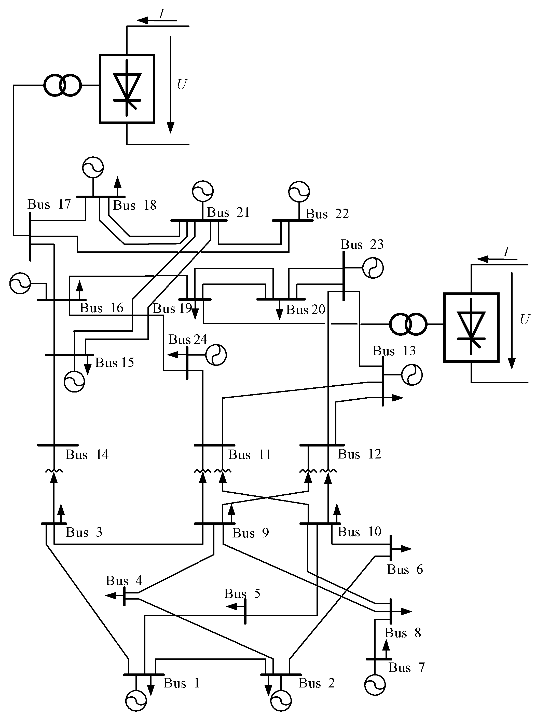
Based on the IEEE RTS-79 basic system [31], corresponding improvements were needed for the simulation. The system structure is shown in Figure 1, which included 24 buses, 38 AC lines, and 2 DC lines. HVDC transmission lines were connected to the system at buses 17 and 19. The specific parameters are shown in Appendix A Table A1, Table A2, Table A3, Table A4 and Table A5. Bus 24 was selected as the balanced node. Eight overhead transmission lines and five transformers are included. The information of the lines to be maintained is shown in Table 1 and Table 2. The maintenance period was 1 month. The maintenance period was in units of days. Overhead transmission line 4 and transformer 2 could not be maintained at the same time in order to avoid a commutation failure. The total maintenance cost of the AC/DC hybrid transmission grid was 10 million yuan. The cost of maintenance was about 50,000 yuan/(day × team), which doubled during a holiday. The upper limit of the total number of maintenance teams was five teams/day, which means there were no more than five teams required for daily maintenance. The total simulation time was 50,000 h [32].
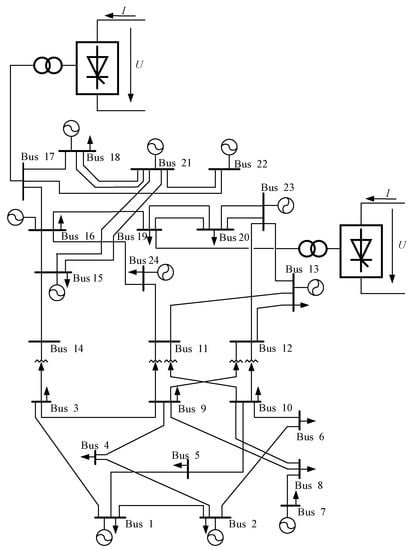
Figure 1.
Improved IEEE reliability test 79 system.

Table 1.
Information of the overhead transmission lines to be maintained.

Table 2.
Information of the transformer to be maintained.
The state of the non-maintenance lines and DC transmission lines was simulated using a random number sampling method. Then, the state was used to calculate the expected energy not supplied for the AC and DC power grids during the maintenance period. As mentioned above, it was assumed that the state of the DC transmission lines follows a normal distribution. Standard normal random numbers were obtained using MATLAB software. was calculated based on Equation (1). As is shown in Figure 2, if was in the interval , the DC transmission line was considered to be at the 0.8 power operating point. Therefore, the state of the DC transmission lines were simulated.
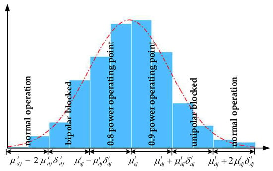
Figure 2.
Simulation for the state of the non-maintenance lines and DC transmission lines.
4.1.2. Effectiveness Verification of the Proposed Method
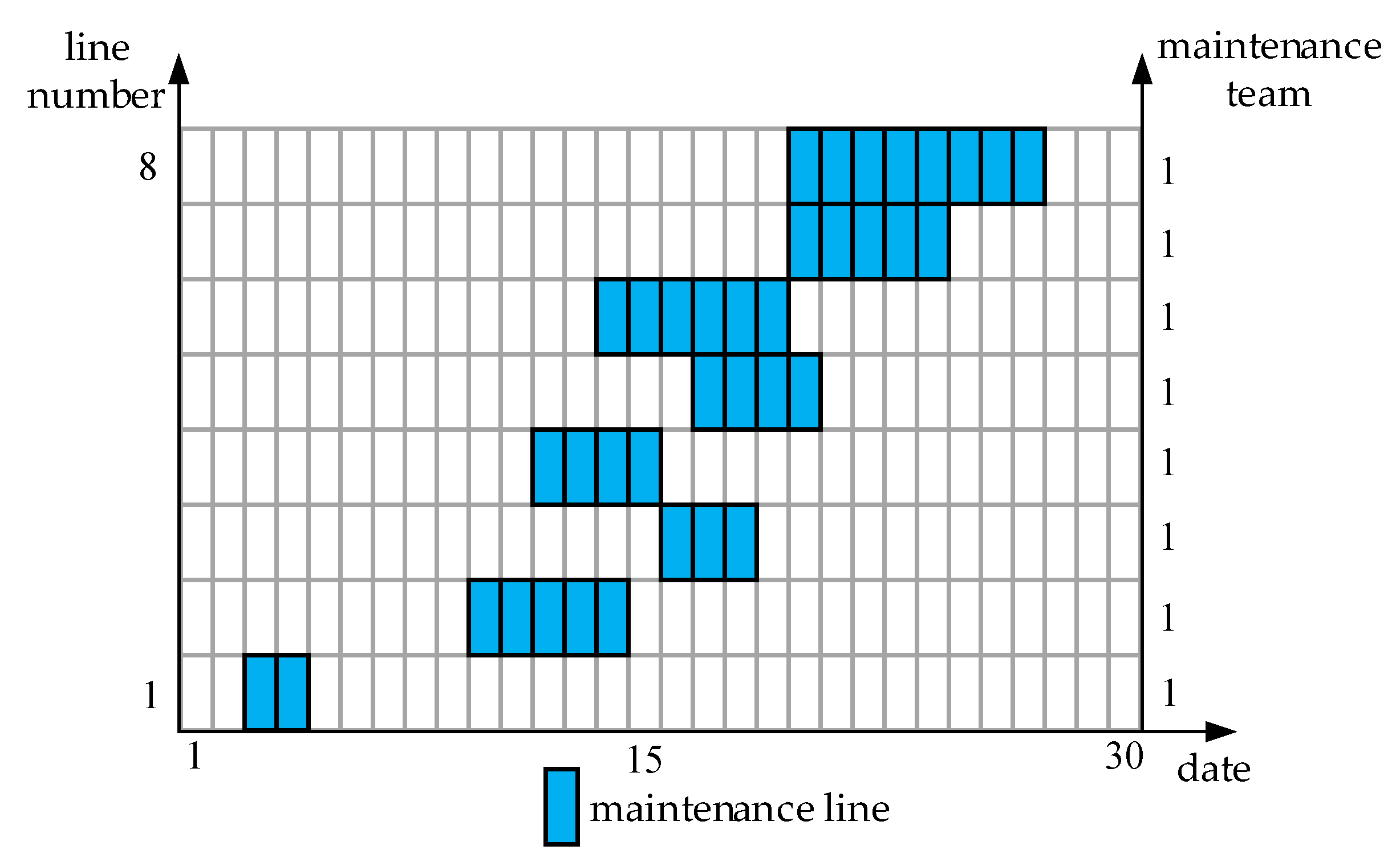
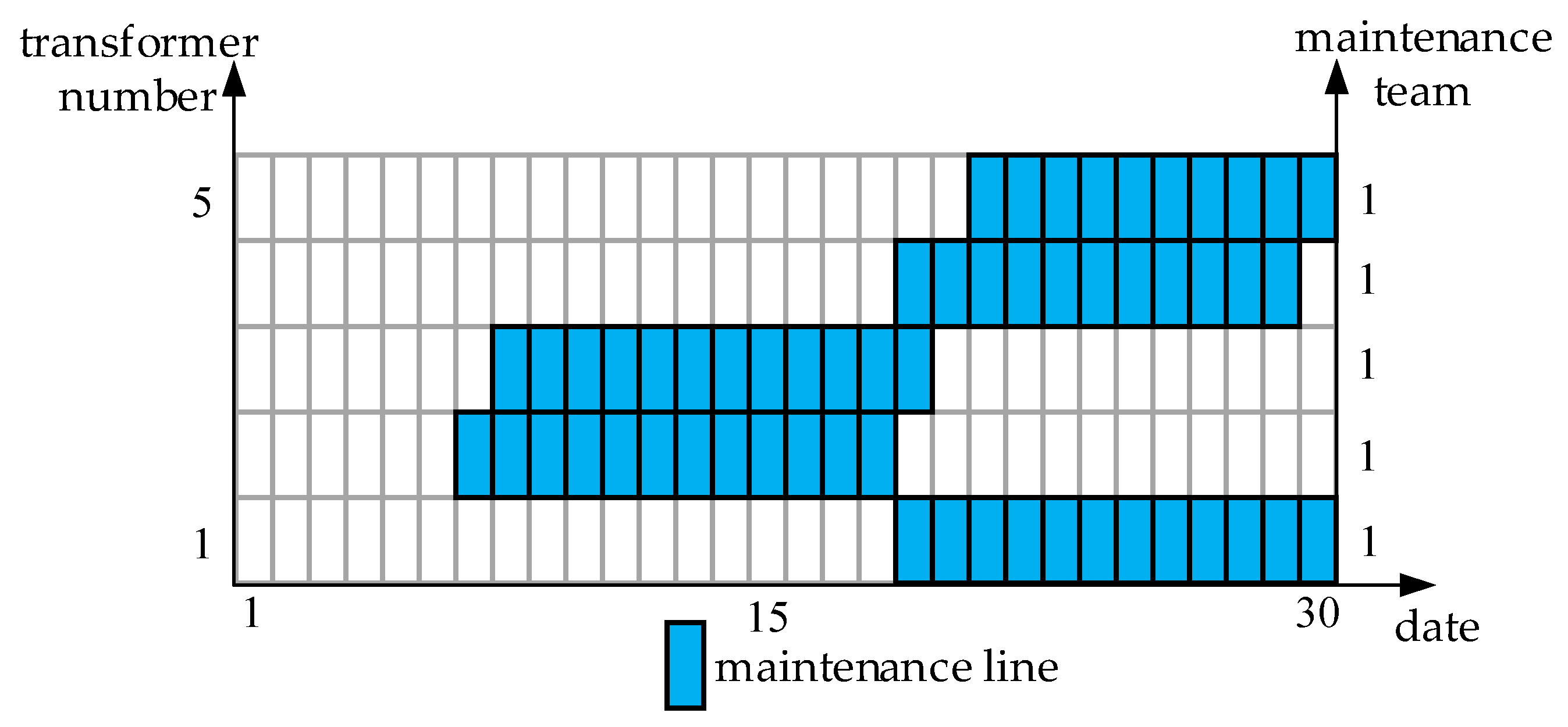
In order to illustrate the effectiveness of the model, two kinds of maintenance scheduling preparation schemes were designed [33]. Solution A artificially drew up the maintenance scheduling based on the information of the line in Table 1 and Table 2, which refers to the Qinghai Power Grid electrical equipment maintenance scheduling and the Henan Luoyang Power Supply Company’s daily maintenance scheduling. Solution B uses the established maintenance optimization model to draw up the maintenance scheduling. The optimized maintenance scheduling is shown in Figure 3 and Figure 4 [34]. The left side of the figures is the number of lines, and the right side is the number of maintenance teams arranged for each line. The blue area indicates that the line was maintained during the period.
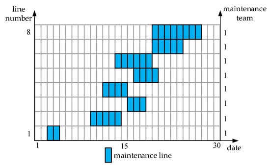
Figure 3.
Overhead transmission line maintenance scheduling and resource arrangement.
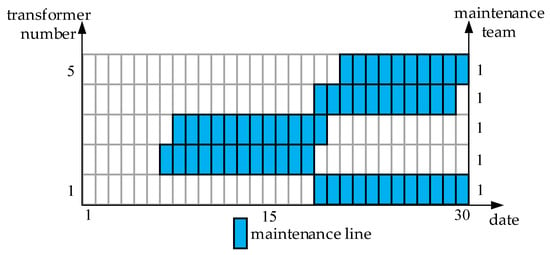
Figure 4.
Transformer maintenance scheduling and resource arrangement.
It can be seen from Figure 3 and Figure 4 that the maintenance scheduling of the overhead transmission lines and transformers were arranged throughout the maintenance period. Centralized maintenance of the lines is to be avoided as much as possible when the maintenance constraints of the power grid are met. Centralized maintenance of the line will put the power grid in high-risk state, which is detrimental to the reliability of the power grid. Only one maintenance team was assigned to each maintenance line. This was due to the constraint that line maintenance should be completed between the start time and the end time. Arranging one maintenance team to each maintenance line is the lowest cost method that can maximally meet the constraints of maintenance cost.
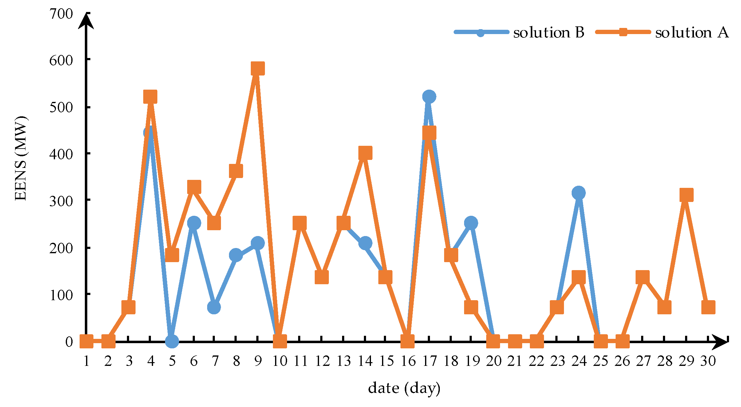
This study also evaluated the reliability of the transmission grid during the maintenance period of solutions A and B. The EENS was used to reflect the reliability of the transmission grid. It can be seen from Figure 5 that the EENS in solution A was higher than that in solution B between day 1 and 16. This was because solution B avoided centralized maintenance of the lines as much as possible. The EENS at days 1, 2, 10, and 16 was 0, which means there was no power loss due to line maintenance and non-maintenance line breaks. However, the EENS in solution B was higher than solution A between days 17 and 30. This was due to the centralized maintenance of transformers and overhead transmission lines, which aimed to meet the constraints of the start and end time. Instead, it can be known from Table 3 that the reliability of the entire maintenance period of solution B was better than solution A. Furthermore, a better optimization effect was achieved. As for the cost of maintenance, solution A looked for a maintenance date such that it holidays as much as possible; therefore, the cost of maintenance in solution A was less than solution B. However, solution A could not accurately measure the interaction between AC and DC transmission systems and comprehensively considered the reliability of the system during the maintenance period.
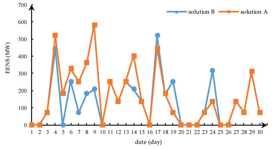
Figure 5.
Comparison of system reliability during maintenance period. EENS: expected energy not supplied.

Table 3.
Information of transformers to be maintained.
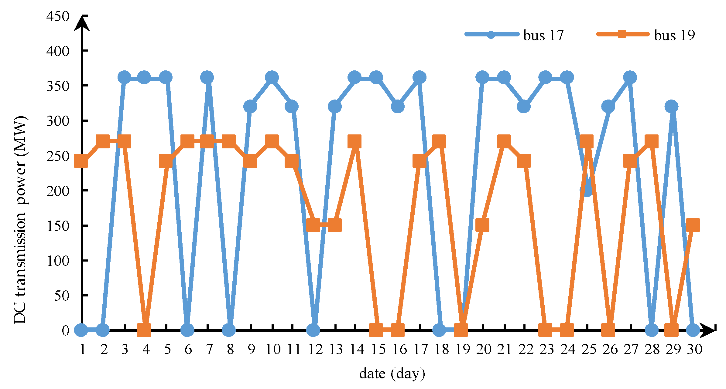
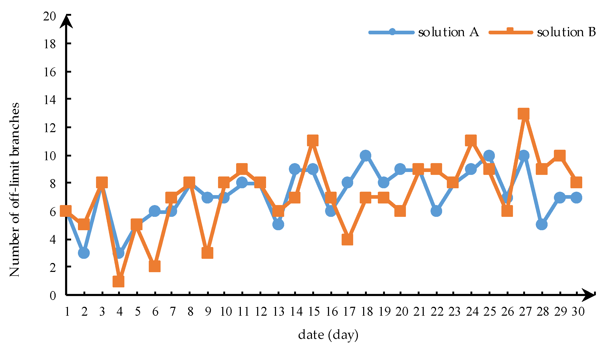
This study comprehensively considered the influence of the DC line state on the off-limit situation of the AC system during the maintenance period. The transmission power of the DC transmission line is shown in Figure 6 for the maintenance period. The number of off-limit power flow is shown in Figure 7. It can be seen from Figure 6 that the bipolar blocking, unipolar blocking, and different power operating points of the DC transmission line are shown. The state of the DC transmission line was more fully simulated. On the 8th day, the DC transmission line at bus 17 experienced bipolar blocking and the number of off-limit branches of solutions A and B were higher than the normal state. The DC transmission line at bus 19 experienced unipolar blocking at 24th. There was a sharp increase in the number of off-limit branches. Judging from the trend of the off-limit power flow branches, solution B was slightly better than solution A. It was shown that the optimization model proposed in this paper could effectively consider the mutual influence mechanism of AC and DC transmission lines and was able to improve the reliability of the system during the maintenance period.
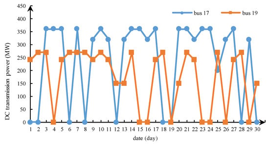
Figure 6.
DC transmission power.
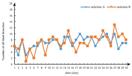
Figure 7.
Branch off-limit power flow during the maintenance period.
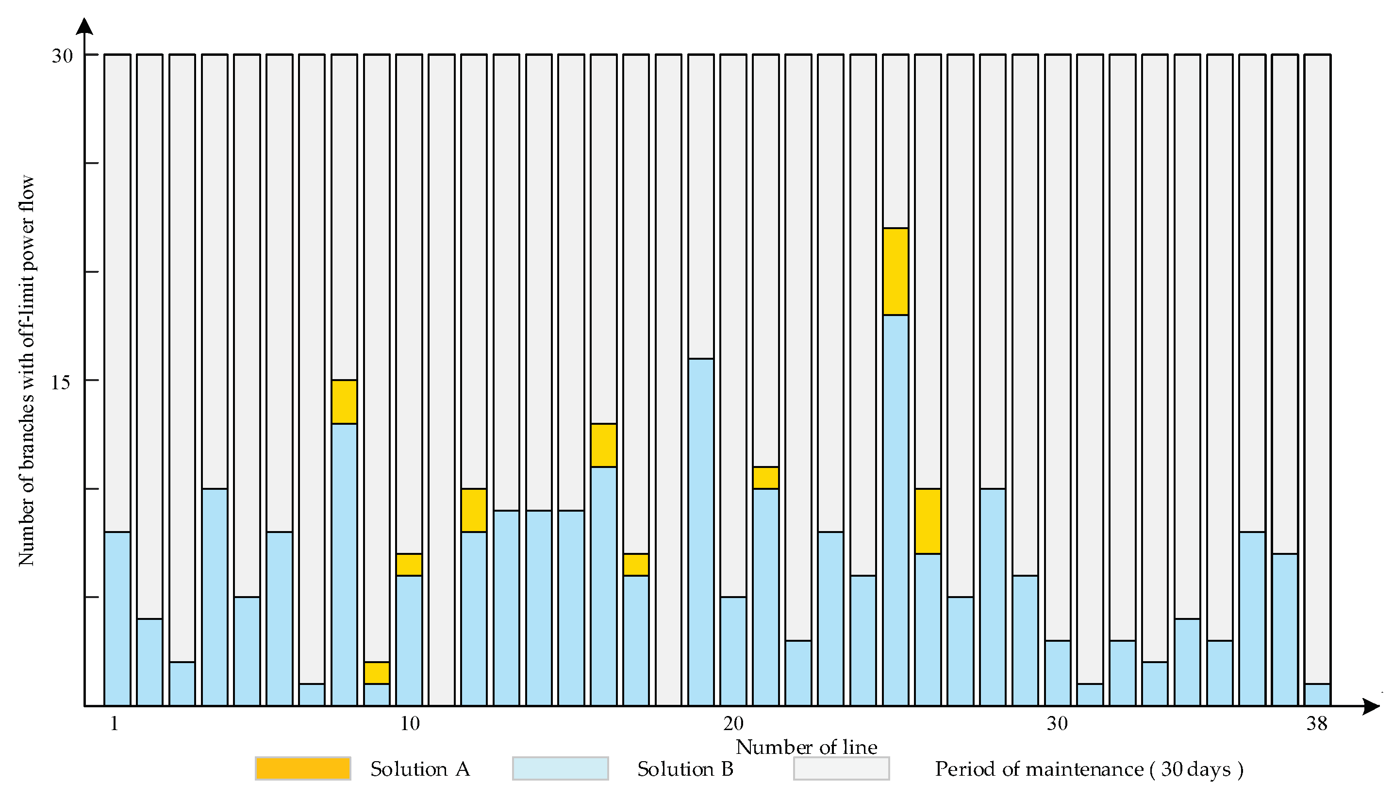
In addition, the off-limit distribution of the branch flow during the maintenance period is shown in Figure 8. It can be seen that the power flow off-limit number of branch 8 (bus 4–bus 9), branch 16 (bus 10–bus 11), and branch 25 (bus 15–bus 21) were significantly higher than the others. There may have been insufficient maximum transmission flow, which could be considered as a weakness in the maintenance period of the AC/DC hybrid transmission network. These branches need to receive more attention.
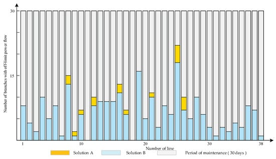
Figure 8.
System power flow off-limit during maintenance period.
4.2. Case Study of the Hubei Province Power System
4.2.1. Case Illustration
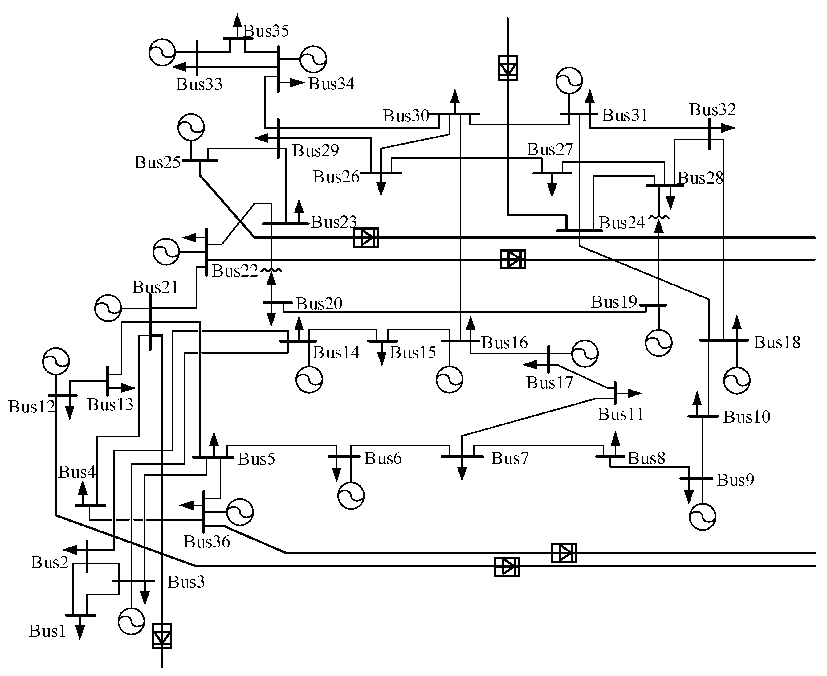
We verified our results in the context of the Chinese electrical system to illustrate the effectiveness of the model. The model was used to obtain a maintenance schedule for the 500 kV and above power grid based on the Hubei Province electrical system in China. The electrical system consisted of 36 buses connected using 47 lines and transformers, as shown in Figure 9. The lines were at two voltages, 500 kV and 1000 kV. There were five DC output lines and one DC input line at buses 12, 21, 22, 25, 36, and 24, respectively, which transmitted power to the East China and Southern Power Grids. It can be seen that the Hubei Province power system is larger than the IEEE RTS 79 test system. Therefore, the interaction of AC and DC systems had a great impact on the maintenance schedule. The model established in this paper was used to optimize the maintenance schedule of the Hubei Province power grid. Bus 36 was the balance node. Eleven overhead transmission lines and two transformers needed to be maintained. The specific information is shown in Table 4 and Table 5. The maximum number of teams was five teams/day, which means no more than five teams were required for daily maintenance.
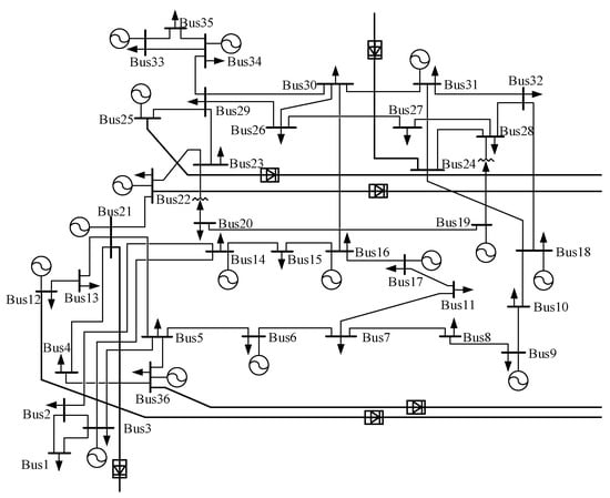
Figure 9.
Hubei Province power system.

Table 4.
Information of the overhead transmission lines to be maintained in Hubei Province.

Table 5.
Information of the transformers to be maintained in Hubei Province.
4.2.2. Effectiveness Verification of the Proposed Method
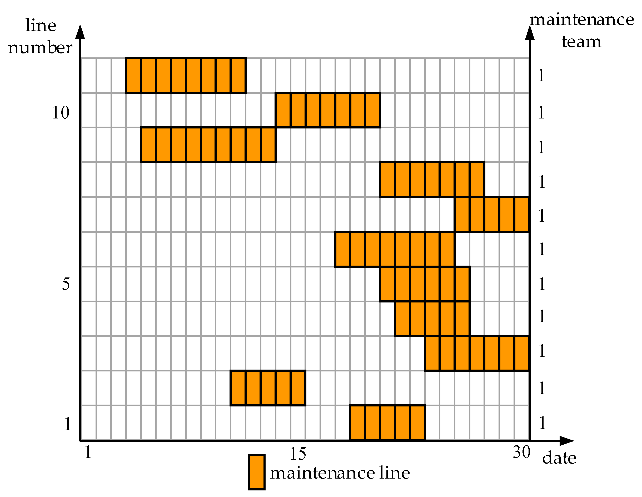
We selected two kinds of solutions to obtain maintenance schedules in order to illustrate the feasibility of the model in the Chinese power grid. Solution C manually arranged the maintenance schedule of the Hubei Province electrical system based on the information of the lines in Table 4 and Table 5. Solution D used the established model to formulate the maintenance schedule. The optimized maintenance scheduling is shown in Figure 10 and Figure 11. The left side of the figure is the route number, and the right side is the number of maintenance teams arranged for each route. The yellow area indicates that the route was maintained during this period.
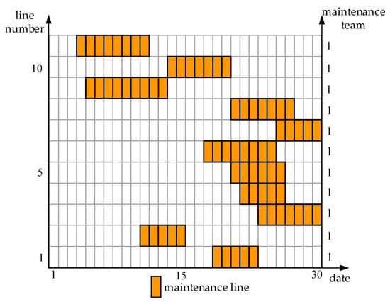
Figure 10.
Overhead transmission line maintenance scheduling and team arrangement.

Figure 11.
Transformer maintenance scheduling and resource arrangement.
As is shown in Figure 10 and Figure 11, the maintenance schedule of the overhead transmission lines and transformers met the start and end time constraints of the maintenance lines well. The number of maintenance work groups scheduled each day did not exceed the maximum limit. Each line was assigned only one team, which could complete the maintenance of the lines at a minimal cost. In conclusion, the maintenance schedule of the Hubei Province electrical system was well optimized.
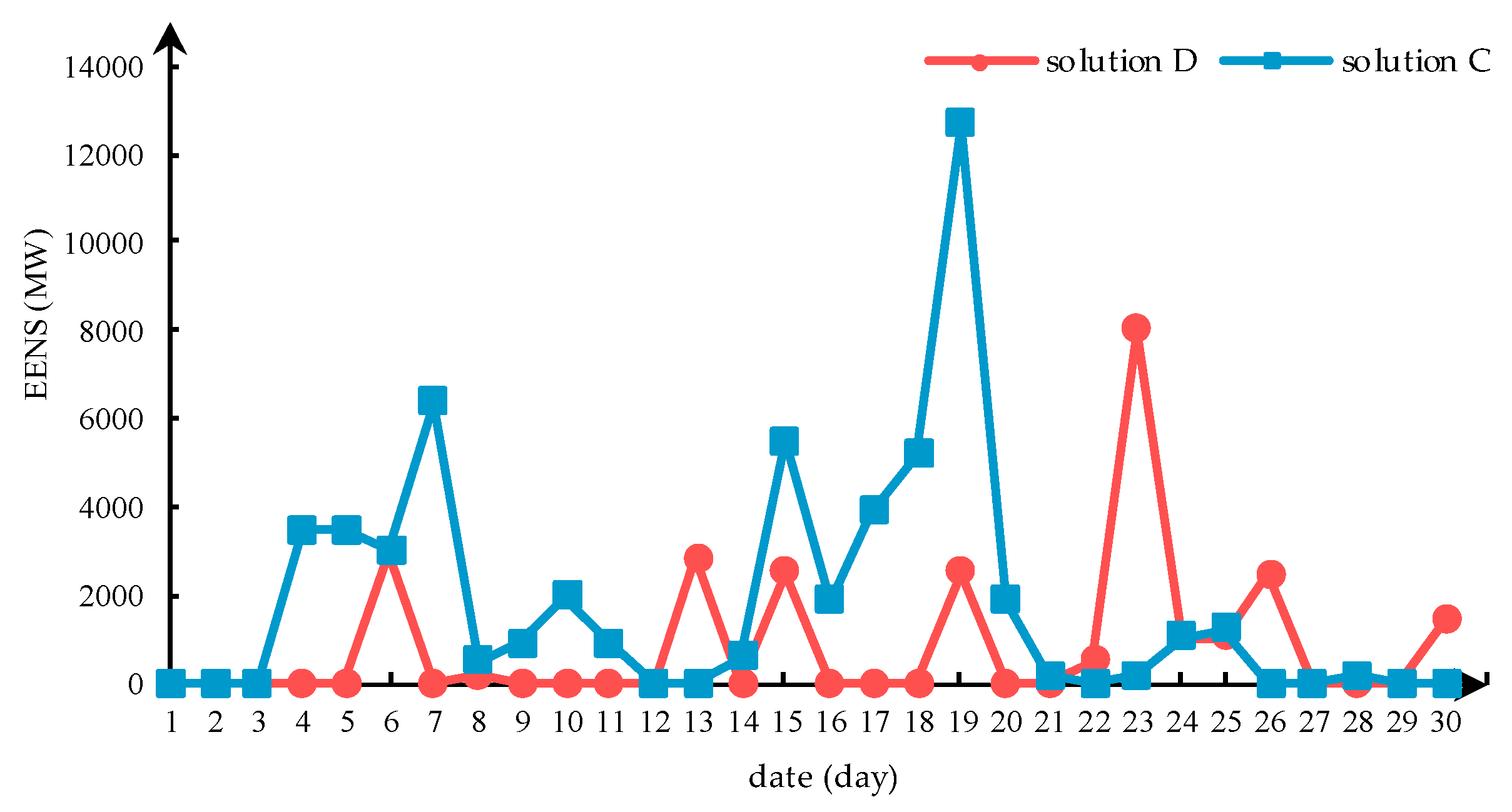
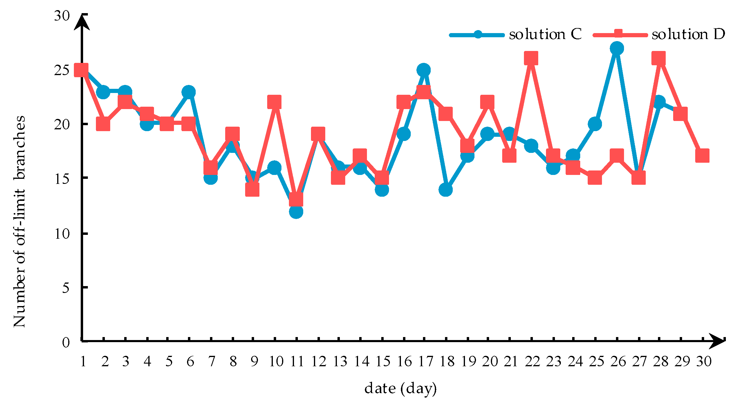
We also analyzed the reliability of the Hubei Province power system during the maintenance period. The EENS was used to reflect the reliability of the system. As is shown in Figure 12, the EENS of solution C was higher than solution D between 1th and 12th. This was because solution D avoided centralized maintenance of the lines as much as possible. However, the EENS of solutions C and D rose sharply between 14th and 20th. One DC input line experienced a bipolar blockage during this time, which caused a large power shortage. Meanwhile, it can be known from Table 6 that the reliability of the entire maintenance period of solution D was better than solution C. As for the cost of maintenance, a better optimization effect was achieved. The cost of maintenance in solution D was less than solution C because the established model avoided maintaining the lines during holidays as much as possible. Furthermore, solution C could not fully measure the interaction between AC and DC power systems and comprehensively consider the reliability of the system during the maintenance period.
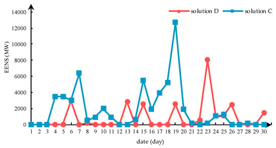
Figure 12.
Comparison of the system reliability during the maintenance period in Hubei Province.

Table 6.
Information of transformer to be maintained in Hubei Province.
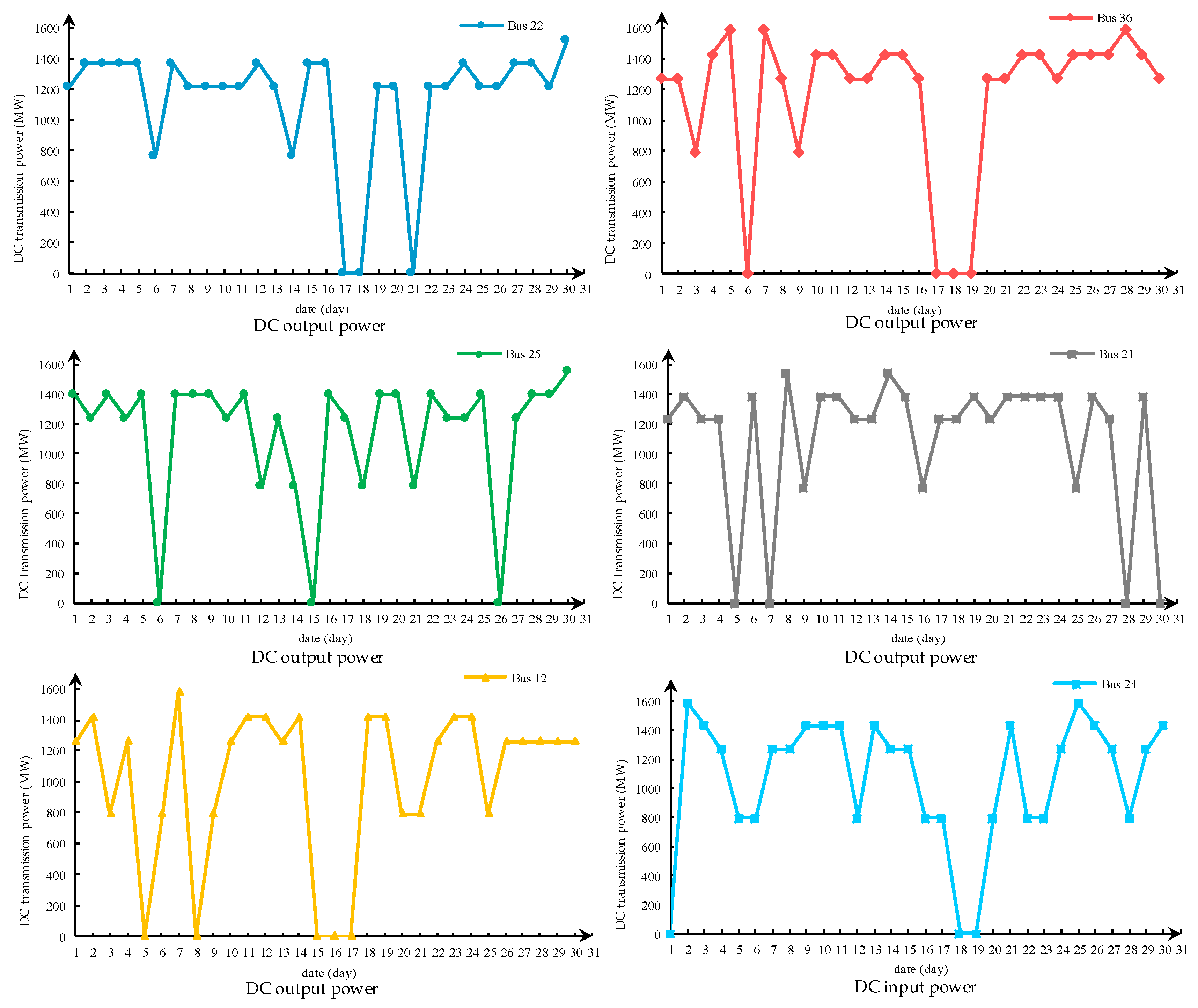
As mentioned earlier, the Hubei Province electrical system consists of five DC output lines and one DC input line. Therefore, the system is more complex than the IEEE test system. The influence of the DC transmission lines on the off-limit situation of the AC system needed to be paid more attention during the maintenance period. The transmission power of DC lines is shown in Figure 13, which includes five DC output lines and one DC input line. The number of off-limit branches is shown in Figure 14. The specific situation of the off-limit branches is shown in Table A8 and Table A9 of the Appendix A during the maintenance period. The state of the DC transmission lines was fully simulated and is presented in Figure 13. It can be seen that the state of the DC transmission lines included bipolar blocking, unipolar blocking, and different power operating points. The DC transmission lines at buses 22, 36, 12, and 24 experienced bipolar blocking between 17th and 20th. Therefore, the number of out-of-flow branches in solutions C and D was higher than normal. At the same time, the more DC lines and more faults meant that the number of out-of-flow branches was higher than for the IEEE test system. Judging from the trend of the out-of-flow branches, solution D was slightly better than solution C in general. This shows that the optimization model proposed in this paper can be applied to the Chinese electrical system. In addition, the model could be used to optimize the maintenance schedule of an AC/DC hybrid system to improve the reliability of the power system during the maintenance period.
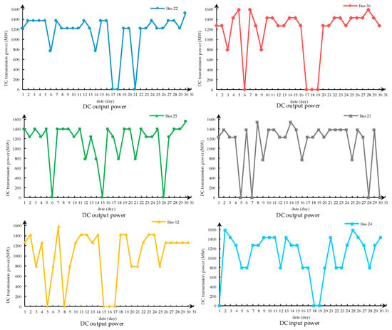
Figure 13.
DC transmission power in Hubei Province.
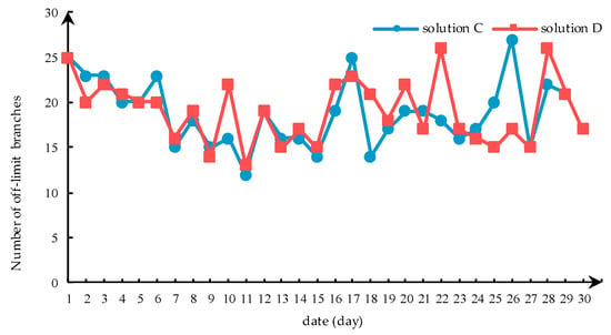
Figure 14.
Off-limit branch power flow during the maintenance period in Hubei Province.
5. Conclusions
In this study, a double-layer substitution method that aimed to linearize the constraints of maintenance resources and maintenance workload was proposed. Based on mixed integer linear programming, the optimization model for the key equipment maintenance scheduling of AC/DC hybrid transmission network was established. According to the case study, the following conclusions can be drawn.
- (1)
- The linearization method proposed in this paper could linearize the non-linear constraints in the original optimization model. Therefore, the original model was transformed into a mixed integer linear optimization model, which could be easily solved.
- (2)
- Compared with the maintenance scheduling that is done manually, the maintenance scheduling obtained by the model in this paper improved the reliability of the system during the maintenance period. It is therefore significant for power companies to formulate maintenance scheduling.
- (3)
- The optimization model established in this paper could effectively avoid the off-limit situations caused by non-maintenance line breaks. It can help to reduce operation risks during maintenance periods.
- (4)
- The optimization model established in this article can be applied to the Chinese electrical system. It contributes to improve the reliability of the Chinese electrical system during maintenance periods.
Author Contributions
J.C. put forward the research direction. S.G. completed the principal analysis and the method design, performed the simulation, and drafted the article. S.L., X.C., and S.M. organized the research activities, provided theoretical guidance, and completed the revision of the article. Y.L. analyzed the simulation results. All six authors were involved in revising the paper. All authors have read and agreed to the published version of the manuscript.
Funding
The work presented was supported by Technology Project of State Grid Hubei Electric Power Company, China (SGHBJY00PSJS1900051).
Conflicts of Interest
The authors declare no conflict of interest.
Appendix A

Table A1.
Type of node.
Table A1.
Type of node.
| Number of Node | Type of Node | Number of Node | Type of Node |
|---|---|---|---|
| 1 | 2 | 13 | 2 |
| 2 | 2 | 14 | 1 |
| 3 | 1 | 15 | 2 |
| 4 | 1 | 16 | 2 |
| 5 | 1 | 17 | 1 |
| 6 | 1 | 18 | 2 |
| 7 | 2 | 19 | 1 |
| 8 | 1 | 20 | 1 |
| 9 | 1 | 21 | 2 |
| 10 | 1 | 22 | 2 |
| 11 | 1 | 23 | 2 |
| 12 | 1 | 24 | 3 |
| (26) |

Table A2.
Node load.
Table A2.
Node load.
| Number of Node | Load (MW) | Number of Node | Load (MW) |
|---|---|---|---|
| 1 | 108 | 13 | 265 |
| 2 | 97 | 24 | 194 |
| 3 | 180 | 15 | 317 |
| 4 | 74 | 16 | 100 |
| 5 | 71 | 17 | 0 |
| 6 | 136 | 18 | 333 |
| 7 | 125 | 19 | 181 |
| 8 | 171 | 20 | 128 |
| 9 | 175 | 21 | 0 |
| 10 | 195 | 22 | 0 |
| 11 | 0 | 23 | 0 |
| 12 | 0 | 14 | 0 |

Table A3.
Generator output.
Table A3.
Generator output.
| Generator Node | Generator Output (MW) |
|---|---|
| 1 | 20 |
| 2 | 20 |
| 7 | 100 |
| 13 | 197 |
| 24 | 0 |
| 15 | 12 |
| 16 | 155 |
| 18 | 400 |
| 21 | 400 |
| 22 | 50 |
| 23 | 155 |

Table A4.
Branch information.
Table A4.
Branch information.
| Head Node | End Node | Number of Branch | Reactance (Ω) | Maximum Transmission Power (MW) |
|---|---|---|---|---|
| 1 | 2 | 1 | 0.0139 | 200 |
| 1 | 3 | 2 | 0.2112 | 220 |
| 1 | 5 | 3 | 0.0845 | 200 |
| 2 | 4 | 4 | 0.1267 | 220 |
| 2 | 6 | 5 | 0.192 | 175 |
| 3 | 9 | 6 | 0.119 | 175 |
| 3 | 14 | 7 | 0.0839 | 600 |
| 4 | 9 | 8 | 0.1037 | 220 |
| 5 | 10 | 9 | 0.0883 | 200 |
| 6 | 10 | 10 | 0.0605 | 200 |
| 7 | 8 | 11 | 0.0614 | 220 |
| 8 | 9 | 12 | 0.1651 | 220 |
| 8 | 10 | 13 | 0.1651 | 200 |
| 9 | 11 | 14 | 0.0839 | 600 |
| 9 | 12 | 15 | 0.0839 | 200 |
| 10 | 11 | 16 | 0.0839 | 400 |
| 10 | 12 | 17 | 0.0839 | 220 |
| 11 | 13 | 18 | 0.0476 | 625 |
| 11 | 24 | 19 | 0.0418 | 800 |
| 12 | 13 | 20 | 0.0476 | 220 |
| 12 | 23 | 21 | 0.0966 | 220 |
| 13 | 23 | 22 | 0.0865 | 200 |
| 24 | 16 | 23 | 0.0389 | 510 |
| 15 | 16 | 24 | 0.0173 | 220 |
| 15 | 21 | 25 | 0.049 | 220 |
| 15 | 21 | 26 | 0.049 | 220 |
| 15 | 14 | 27 | 0.0519 | 400 |
| 16 | 17 | 28 | 0.0259 | 200 |
| 16 | 19 | 29 | 0.0231 | 510 |
| 17 | 18 | 30 | 0.0144 | 200 |
| 17 | 22 | 31 | 0.1053 | 175 |
| 18 | 21 | 32 | 0.0259 | 175 |
| 18 | 21 | 33 | 0.0259 | 175 |
| 19 | 20 | 34 | 0.0396 | 200 |
| 19 | 20 | 35 | 0.0396 | 200 |
| 20 | 23 | 36 | 0.0216 | 175 |
| 20 | 23 | 37 | 0.0216 | 175 |
| 21 | 22 | 38 | 0.0678 | 175 |

Table A5.
DC power.
Table A5.
DC power.
| Number of Node | Rated Transmission Power (MW) |
|---|---|
| 17 | 400 |
| 19 | 300 |

Table A6.
Solution A off-limit branch power flow.
Table A6.
Solution A off-limit branch power flow.
| Number of Branch | Maintenance Period 1–30 Days (1 represents an off-limit branch power flow) |
|---|---|
| 1–2 | 000000000011000001000001010000 |
| 1–3 | 000000000011000000100000000000 |
| 1–5 | 000000000000000000001000000010 |
| 2–4 | 001000011000011011000001011000 |
| 2–6 | 000001000010000001000100010000 |
| 3–9 | 100100000111000010100000000100 |
| 3–14 | 000000000000000000100000000000 |
| 4–9 | 011000011000111111000001111010 |
| 5–10 | 000000000000000000001000000010 |
| 6–10 | 000011000000000001101100010000 |
| 7–8 | 000000000000000000000000000000 |
| 8–9 | 000000011100001010010111100000 |
| 8–10 | 000000000000000010011111100000 |
| 9–11 | 010000001100010000000000000100 |
| 9–12 | 001000011110001100000000000000 |
| 10–11 | 010100000000000011011111110110 |
| 10–12 | 000001100000000001010110100000 |
| 11–13 | 000000000000000000000000000000 |
| 11–24 | 010110001100011001001111010110 |
| 12–13 | 000001001000001001000100000000 |
| 12–23 | 001001110110100000010010100001 |
| 13–23 | 000000000000001000000000000100 |
| 24–16 | 101000100000000000110000101001 |
| 15–16 | 100000000000100000100000000000 |
| 15–21 | 111011011111111110010011101011 |
| 15–21 | 000000010010011101110010000001 |
| 15–14 | 100000000000000000100000000001 |
| 16–17 | 000000001000100000001001000110 |
| 16–19 | 001000100000000000010000101001 |
| 17–18 | 000000000000000100000000000000 |
| 17–22 | 000000000000000000000000000000 |
| 18–21 | 000000000001000110000000000000 |
| 18–21 | 000000000000000000000000000000 |
| 19–20 | 001000100100000000000000000100 |
| 19–20 | 000000000000000000010000001001 |
| 20–23 | 000000011100000000001000100000 |
| 20–23 | 001000001100000000011000000101 |
| 21–22 | 000000000000000000000000000000 |

Table A7.
Solution B off-limit branch power flow.
Table A7.
Solution B off-limit branch power flow.
| Number of Branch | Maintenance Period 1–30 Days (1 represents an off-limit branch power flow) |
|---|---|
| 1–2 | 010000000110001001000001010010 |
| 1–3 | 010000000011000001000000000000 |
| 1–5 | 000000000000001000000000000010 |
| 2–4 | 011000000000001000101101011010 |
| 2–6 | 000000000100000101000100010000 |
| 3–9 | 100000000001000001001110001100 |
| 3–14 | 000000000001000000000000000000 |
| 4–9 | 011010000000001000111101111010 |
| 5–10 | 000000000000001000000000000000 |
| 6–10 | 000001110100000101000000000000 |
| 7–8 | 000000000000000000000000000000 |
| 8–9 | 000000000010000000001111101100 |
| 8–10 | 000000000010100110000111100100 |
| 9–11 | 010000000000000000001111110110 |
| 9–12 | 001000100000000000001110101011 |
| 10–11 | 010000001110111111000000000001 |
| 10–12 | 000000010110001000110000000000 |
| 11–13 | 000000000000000000000000000000 |
| 11–24 | 010110001100011101001111010110 |
| 12–13 | 000000001000011000000100000010 |
| 12–23 | 001000100110100000010010101001 |
| 13–23 | 000000001000000000000000001100 |
| 24–16 | 101000100001000000010000101001 |
| 15–16 | 100000101000100000100001000000 |
| 15–21 | 101011011111111110000000101011 |
| 15–21 | 000000010010011100000010000001 |
| 15–14 | 100000110001000000100000000000 |
| 16–17 | 010000011001100000001001001110 |
| 16–19 | 001000100000000000010000101001 |
| 17–18 | 000000000001000000000001001000 |
| 17–22 | 010000000000000000000000000000 |
| 18–21 | 000000000001010010000000000000 |
| 18–21 | 000000010000000000000001000000 |
| 19–20 | 001000000100000000100000000100 |
| 19–20 | 000000000000000000010000001001 |
| 20–23 | 000000011101000000101000101000 |
| 20–23 | 001000001100000000011000000101 |
| 21–22 | 010000000000000000000000000000 |

Table A8.
Solution C off-limit branch power flow in the Hubei electrical system.
Table A8.
Solution C off-limit branch power flow in the Hubei electrical system.
| Number of Branch | Maintenance Period 1–30 Days (1 represents an off-limit branch power flow) |
|---|---|
| 1–2 | 110110111110011111000000010110 |
| 3–2 | 110101111011000010000000010000 |
| 3–1 | 001001000001000000101000000001 |
| 3–5 | 100100010011011010110000010011 |
| 36–4 | 001010000000000010000011011010 |
| 5–36 | 100101101011100000110000000101 |
| 5–6 | 111001000000000000110110110100 |
| 8–7 | 100000000001000000110101100100 |
| 6–7 | 111001000000000000010100110100 |
| 9–10 | 110000000001000000110101100100 |
| 8–9 | 110000000001000000110101100100 |
| 18–10 | 110000000001000000110101100100 |
| 32–18 | 000000000000000000011101100000 |
| 11–17 | 001001111001000100001110111000 |
| 11–7 | 001001111000000100000010010000 |
| 16–30 | 101101111010011010100000010011 |
| 16–15 | 011011000000100011001000100100 |
| 16–17 | 001001111000000100001000110000 |
| 15–14 | 111111110111111011111011111111 |
| 14–2 | 111111000101111111001000000111 |
| 14–3 | 111110011110111011111100110111 |
| 12–13 | 101111011100101110011100111111 |
| 4–21 | 001011000000000010000011011110 |
| 21–13 | 101111011100101110011100111111 |
| 21–5 | 101000000000001010000101101010 |
| 22–21 | 000010000000100101000010011000 |
| 19–20 | 101111100111010011111111111111 |
| 28–19 | 010010000000000001000001011000 |
| 23–20 | 010010000000000001000001011000 |
| 22–23 | 010010000100110101000011011000 |
| 23–29 | 111111100100111111111011110011 |
| 25–29 | 010101000101111011001011011000 |
| 26–29 | 010011101001000000101010000001 |
| 26–27 | 000101100110000010001110000001 |
| 26–30 | 000111100110000110000100000000 |
| 24–28 | 010100010001110110110000100011 |
| 24–18 | 111000110001100110111011100110 |
| 24–31 | 110100010000110110010000000100 |
| 28–27 | 011111110110010011001111111111 |
| 32–28 | 101000000001001000001100000110 |
| 32–31 | 101000011100011100000000010111 |
| 30–31 | 101100011100111110101100010011 |
| 30–29 | 100100010110110100000010011110 |
| 34–29 | 000000000000000000000000000000 |
| 33–34 | 000000000000000000000000000000 |
| 35–34 | 010010001001000110000000010000 |
| 35–33 | 010011001001000111010000000010 |

Table A9.
Solution D off-limit branch power flow in the Hubei electrical system.
Table A9.
Solution D off-limit branch power flow in the Hubei electrical system.
| Number of Branch | Maintenance Period 1–30 Days (1 represents an off-limit branch power flow) |
|---|---|
| 1–2 | 110111111110011111000000010110 |
| 3–2 | 110100111011000010000000010000 |
| 3–1 | 000000000001000000111110000001 |
| 3–5 | 100100010011011010110101011011 |
| 36–4 | 001010000100000010000011000000 |
| 5–36 | 100101000011100000110000000101 |
| 5–6 | 101001000000000101010100000100 |
| 8–7 | 100000000001000101110100000100 |
| 6–7 | 101001000000000001010100000100 |
| 9–10 | 100000000001000101110100000100 |
| 8–9 | 100000000001000101110100000100 |
| 18–10 | 100000000001000101110100000100 |
| 32–18 | 000000111000001100011100000000 |
| 11–17 | 011001111001010000000010111110 |
| 11–7 | 001001111000000000000000100100 |
| 16–30 | 101111111010011010100100000011 |
| 16–15 | 011011000100100111001000100100 |
| 16–17 | 011001111000010000000000100110 |
| 15–14 | 111111010011111111111101111111 |
| 14–2 | 111111100101111111000100000111 |
| 14–3 | 111110111110111011111111101111 |
| 12–13 | 101111011100101110011100111111 |
| 4–21 | 011011000100000010000011000000 |
| 21–13 | 101111011100101110011100111111 |
| 21–5 | 101000010000001011000101100010 |
| 22–21 | 000010000100100000000011011000 |
| 19–20 | 111111000111010010101111011011 |
| 28–19 | 010010100000000001010001111100 |
| 23–20 | 010010100000000001010001111100 |
| 22–23 | 010010000100100101000011011000 |
| 23–29 | 110111000100111110111111100111 |
| 25–29 | 010101000101111011001011011000 |
| 26–29 | 000010001001000000101110100001 |
| 26–27 | 000101100110000010001010000001 |
| 26–30 | 000111100110000110000000000000 |
| 24–28 | 000100010101110100110000100011 |
| 24–18 | 111010111001000101111001100110 |
| 24–31 | 110100011100110100010100000100 |
| 28–27 | 011111110110010010011010010111 |
| 32–28 | 101000000101001000101100000110 |
| 32–31 | 101000000000011011100110010111 |
| 30–31 | 101100011100111111101110010011 |
| 30–29 | 101100010110110101000110011110 |
| 34–29 | 000000000000000000000000000000 |
| 33–34 | 000000000000000000000000000000 |
| 35–34 | 010100100111000110000101001000 |
| 35–33 | 010000000001000111011111001010 |
References
- State Grid Corporation of China. “13th Five-Year Plan” of State Grid Corporation of China; State Grid Corporation of China: Beijing, China, 2015. [Google Scholar]
- Wei, D.; Zheng, W.; Li, K.; Xiao, Y.; Wei, P.; Xiao, H. Coordinated Control Technology for AC/DC Hybrid System. High Volt. Eng. 2019, 45, 3025–3038. [Google Scholar]
- Tong, W. Hybrid Transient Simulation and Parallel Computing of Large-Scale AC/DC Power System. Master’s Thesis, Zhejiang University, Hangzhou, China, 2019. [Google Scholar]
- Xu, X.F.; Huang, M.X.; Wang, T.T.; Chen, X.L. Optimization of short-term complex distribution network maintenance scheduling. J. Zhejiang Univ. Eng. Sci. 2010, 44, 510–515. [Google Scholar]
- Liu, W.; Xie, C.; Wen, J.; Wang, J.; Wang, W. Optimization of trans-mission network maintenance scheduling based on niche multi-objective particle swarm algorithm. Proc. CSEE 2013, 33, 141–148. [Google Scholar]
- Gao, W.; Wang, J.; Lu, J.; Xu, K. Maintenance schedule of transmission system based on equal risk. Autom. Electr. Power Syst. 2012, 36, 6–11. [Google Scholar]
- Xu, X.; Huang, M.; Wang, T.; Qiu, J. Optimization of transmission line maintenance scheduling based on chance-constrained bilevel programming. Autom. Electr. Power Syst. 2009, 33, 25–29. (In Chinese) [Google Scholar]
- Yan, W.; Lin, Y.; Luo, X.; Zhao, L.; Yu, J. An optimization security correction method for maintenance scheduling considering load transfer. Autom. Electr. Power Syst. 2010, 34, 92–96. [Google Scholar]
- Rao, R.S.; Narasimham, S.V.L.; Ramalingaraju, M.; Rao, A.S. Optimal network reconfiguration of large-scale distribution system using harmony search algorithm. IEEE Trans. Power Syst. 2011, 26, 1080–1088. [Google Scholar]
- Huang, X.C.; Shu, J.; Zhang, L.Z.; Zhu, G.Y. Distribution maintenance scheduling using an intelligent optimal approach mixed with immune algorithm and tabu search. Proc. CSEE 2004, 24, 96–100. [Google Scholar]
- Teng, G.; Fang, S. Condition based maintenance optimization for distribution networks with DG based on game theory. Electr. Meas. Instrum. 2019, 56, 1001–1390. [Google Scholar]
- Li, E.; Kang, C.; Li, Y.; Fan, Y.; Ma, G.; Du, Y. Optimization model of distribution network maintenance scheduling based on equipment condition evaluation and grid loss risk. High Volt. Eng. 2018, 44, 3751–3759. (In Chinese) [Google Scholar]
- Wang, S.H.; Zhang, Y.D.; Ji, G.L. Survey on Theories and Applications of Swarm Intelligence Algorithms. J. Nanjing Norm. Univ. Eng. Technol. Ed. 2014, 14, 31–38. [Google Scholar]
- Li, C.; Miao, S.; Sheng, W.; Zhang, D.; Hu, S. Optimization Operation Strategy of Active Distribution Network Considering Dynamic Network Reconfiguration. Trans. China Electrotech. Soc. 2019, 34, 3910–3919. [Google Scholar]
- Sereeter, B.; van Westering, W.; Vuik, C.; Witteveen, C. Linear Power Flow Method Improved with Numerical Analysis Techniques Applied to a Very Large Network. Energies 2018, 12, 4078. [Google Scholar] [CrossRef]
- Huang, Z.; Wang, X.; Tong, X. Digital substation communication network simulation based on EPOCHS. Autom. Electr. Power Syst. 2009, 33, 71–89. [Google Scholar]
- Huang, Y.; Li, G. Reliability evaluation of distributed integrated energy systems via Markov chain Monte Carlo. In Proceedings of the 2017 IEEE Conference on Energy Internet and Energy System Integration (EI2), Beijing, China, 26–28 November 2017; pp. 1–5. [Google Scholar]
- Wang, Y.; Han, X.; Ding, Y.; Shen, J. Markov chain-based rapid assessment on operational reliability of power grid. Power Syst. Technol. 2013, 37, 405–410. [Google Scholar]
- Xiao, Z.; Yu, W.; Hui, J. Reliability evaluation of photovoltaic power plant based on Markov Chain Monte Carlo method. High Volt. Eng. 2017, 43, 1034–1042. [Google Scholar]
- Chang, S.; Xin, N.; Zhi, S. Quantitative risk assessment of distribution network based on real-time health index of equipment. High Volt. Eng. 2018, 44, 534–540. [Google Scholar]
- Liao, R.; Wang, Y.; Liu, H.; Ma, Z. Research state of condition assessment method for power equipment. High Volt. Eng. 2018, 44, 3454–3464. [Google Scholar]
- Pan, L.; Lu, G.; Zhang, Y.; Yu, G.; Zhu, D. Decision-making optimization of equipment condition-based maintenance according to risk comprehensive evaluation. Autom. Electr. Power Syst. 2010, 34, 28–32. [Google Scholar]
- Huang, J.; Zhao, F.; Cheng, W.; Tan, J.; Wang, J. Optimization of distribution network maintenance scheduling based on risk management method. Power Syst. Prot. Control 2015, 43, 94–100. [Google Scholar]
- Zhi, L.; Xu, D.; Zheng, W. A Bi-Level Optimization Method for Distribution Network Maintenance Schedule Considering Flexible Definition Constraint Condition. Trans. China Electrotech. Soc. 2018, 33, 2208–2216. [Google Scholar]
- Li, R.; Wang, F.; Li, Z. Maintenance decision making optimization based on risk assessment for distribution system. Electr. Power Autom. Equip. 2013, 33, 1–8. [Google Scholar]
- Zhang, H.; Yin, Y.; Shen, H.; He, J.; Zhao, S. Generator maintenance scheduling of large-scale wind power integration considering peak shaving. Autom. Electr. Power Syst. 2012, 36, 25–30. (In Chinese) [Google Scholar]
- Liu, W.; Xie, C.; Wen, J.; Wang, J.; Li, J. Multi-objective decision making method for maintenance scheduling of transmission network. Power Syst. Technol. 2013, 37, 471–476. [Google Scholar]
- Pandzic, H.; Conejo, A.J.; Kuzle, I.; Caro, E. Yearly maintenance scheduling of transmission lines within a market environment. IEEE Trans. Power Syst. 2012, 27, 407–415. [Google Scholar] [CrossRef]
- Li, Z.; Cao, Y.; Dai, L.V.; Yang, X.; Nguyen, T.T. Optimal Power Flow for Transmission Power Networks Using a Novel Metaheuristic Algorithm. Energies 2019, 12, 4310. [Google Scholar] [CrossRef]
- Xu, X.F.; Huang, M.X.; Wang, T.T.; Chen, X.L. Optimization algorithm of power supply equipment maintenance scheduling and its application in regional power network. Power Syst. Technol. 2009, 33, 31–35. (In Chinese) [Google Scholar]
- Reliability Test System Task Force. IEEE reliability test system. IEEE Trans. Power Appar. Syst. 1979, 98, 2047–2054. [Google Scholar]
- Jing, Z.; Yan, L.; Ming, H. The maintenance decision making optimization for distribution networks based on the fuzzy entropy weight of vague set. Trans. China Electrotech. Soc. 2015, 30, 37–45. [Google Scholar]
- Ibrahim, A.A.; Kazemtabrizi, B.; Renedo, J. Security-Constrained Day-Ahead Operational Planning for Flexible Hybrid AC/DC Distribution Networks. Appl. Sci. 2019, 9, 4685. [Google Scholar] [CrossRef]
- Zhou, M.; Xia, S.; Li, Y.; Li, G. A joint optimization approach on monthly unit commitment and maintenance scheduling for wind power integrated power systems. Proceeding CSEE 2015, 35, 1586–1594. [Google Scholar]
© 2020 by the authors. Licensee MDPI, Basel, Switzerland. This article is an open access article distributed under the terms and conditions of the Creative Commons Attribution (CC BY) license (http://creativecommons.org/licenses/by/4.0/).

