A Cloud-Based In-Field Fleet Coordination System for Multiple Operations


Abstract
:
1. Introduction
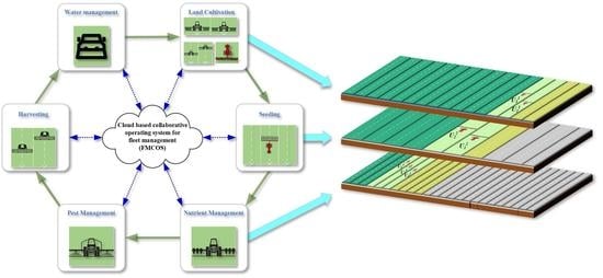
2. Description of the Fleet Management System
2.1. System Composition
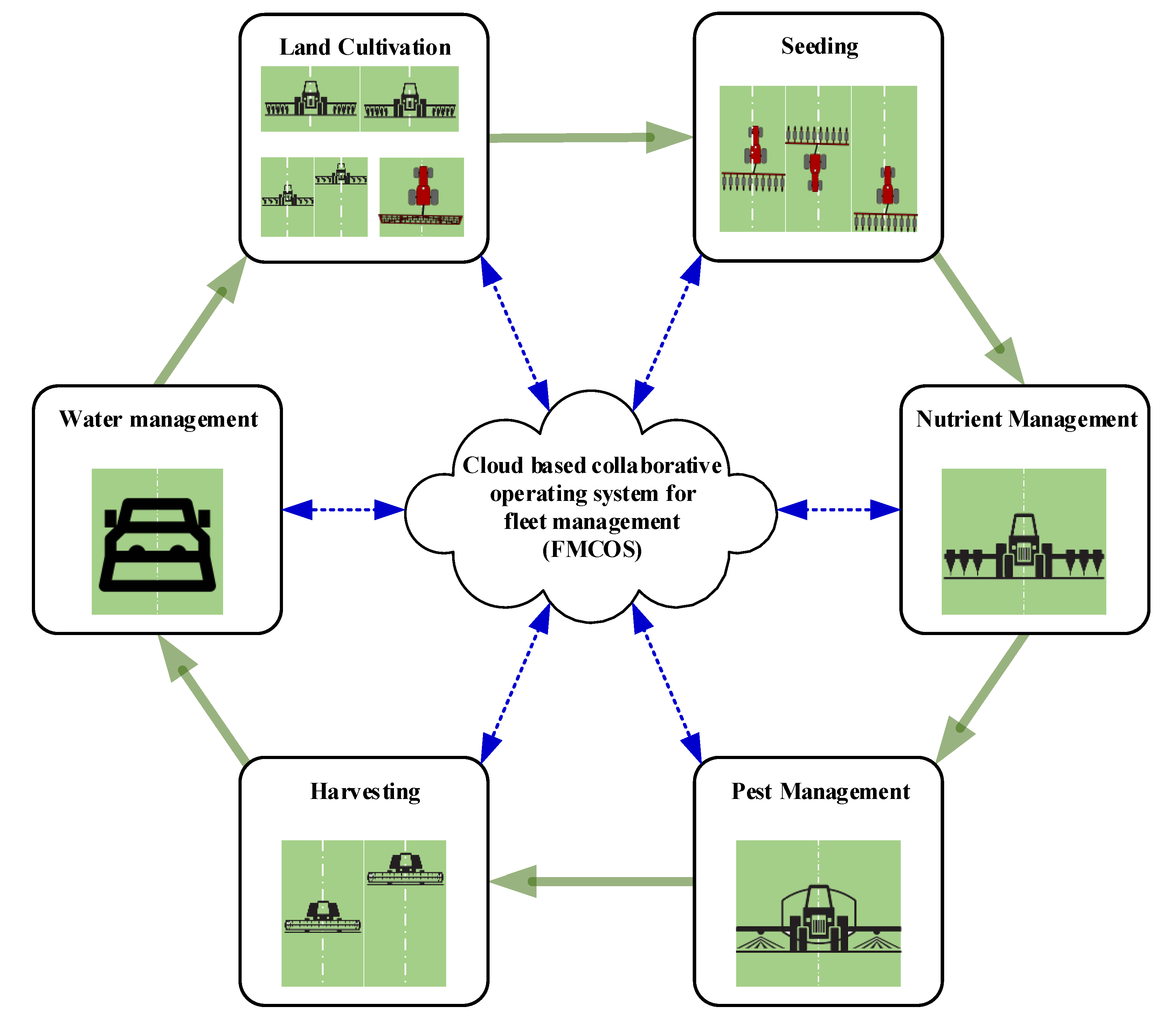
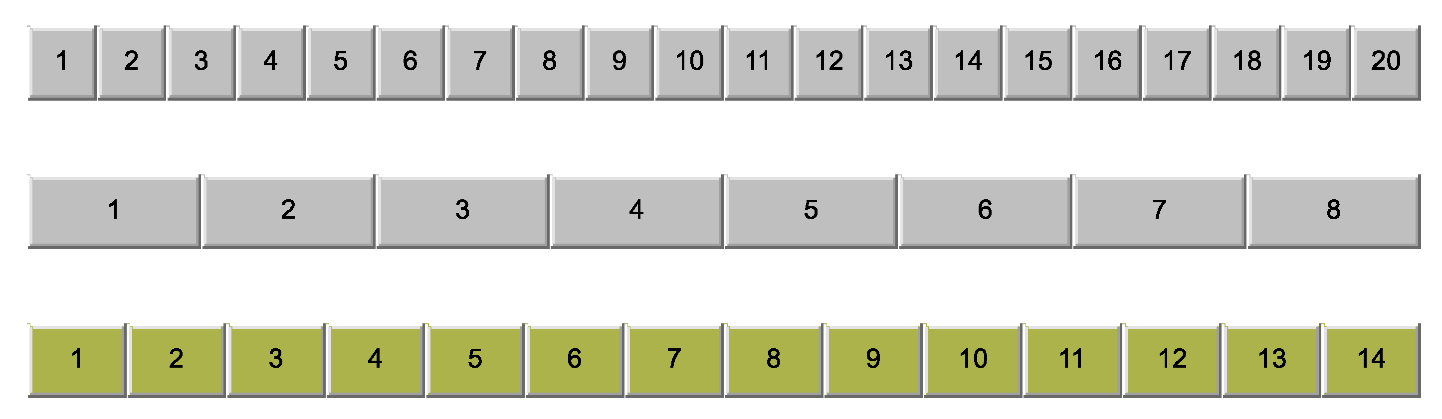
2.2. Operating Strip Segmentation
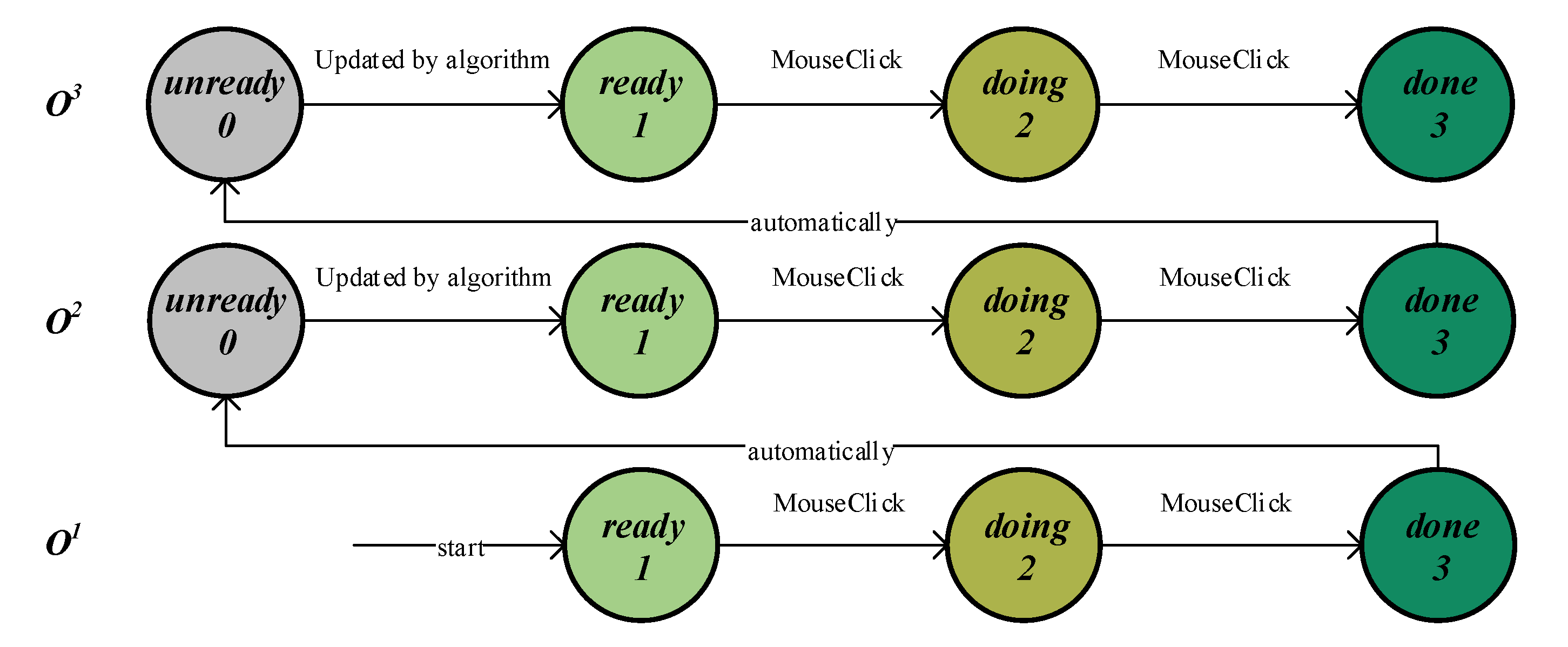
2.3. Sequential Operations Connection
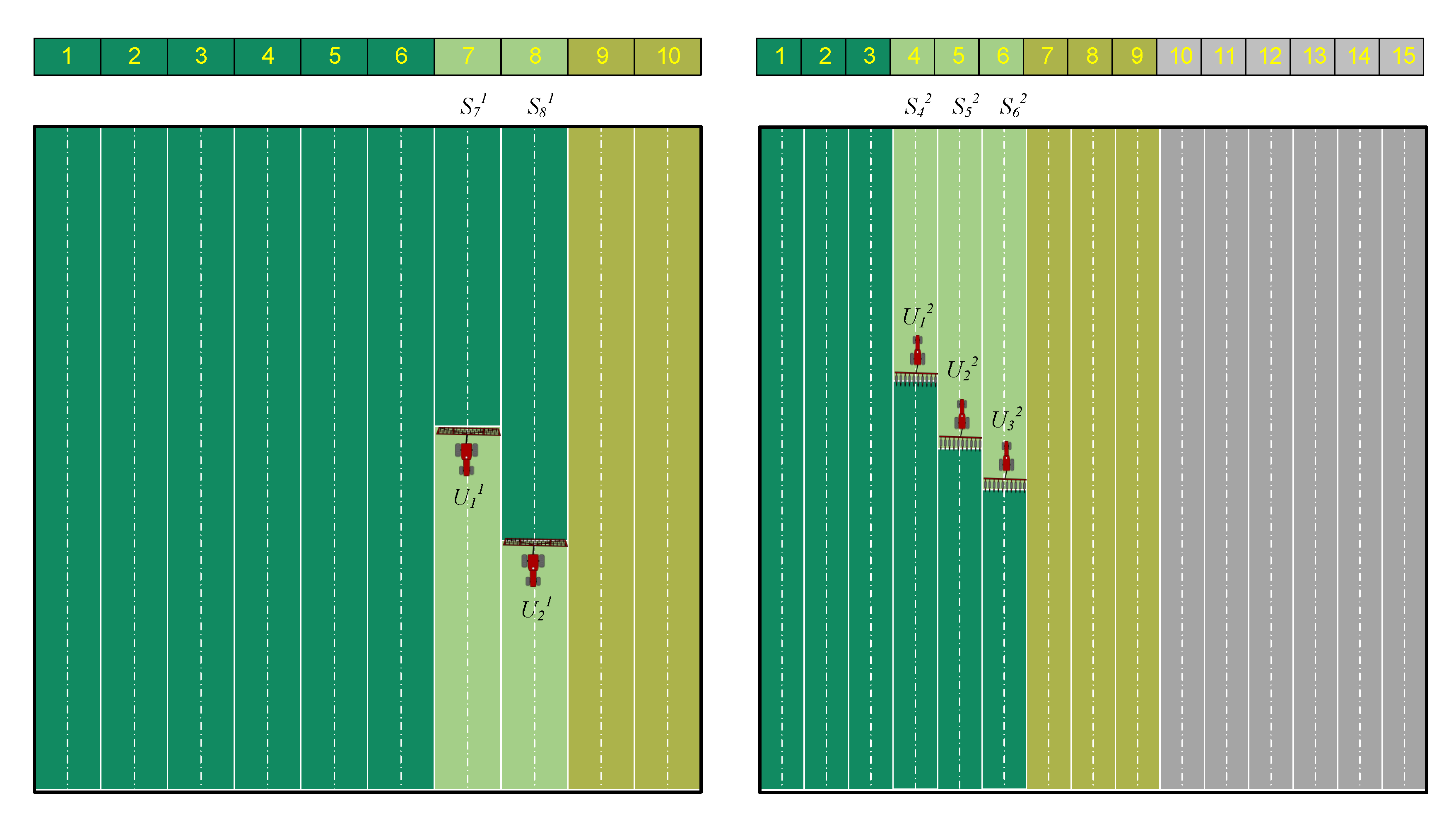
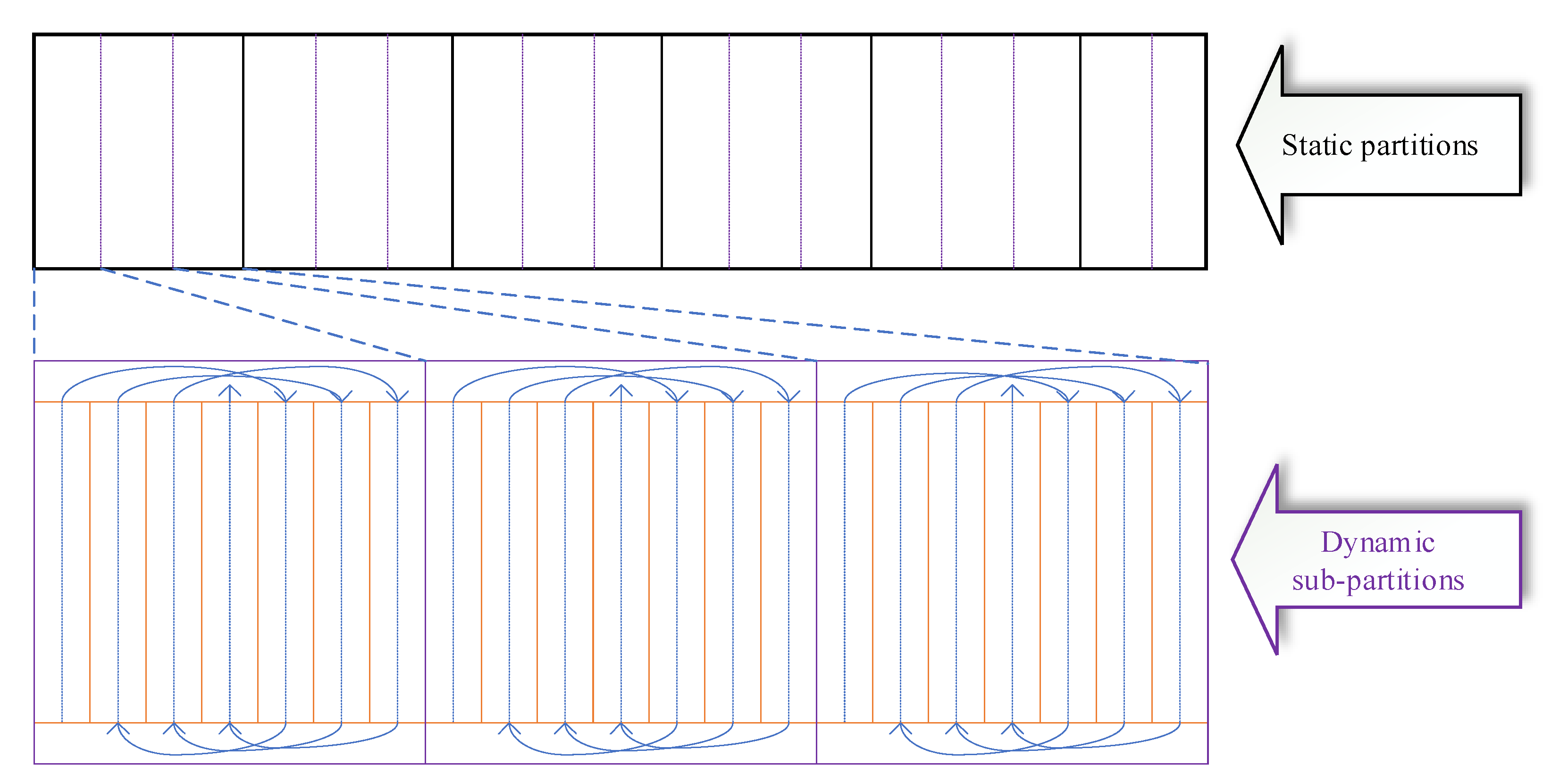
2.3.1. Field Partitioning
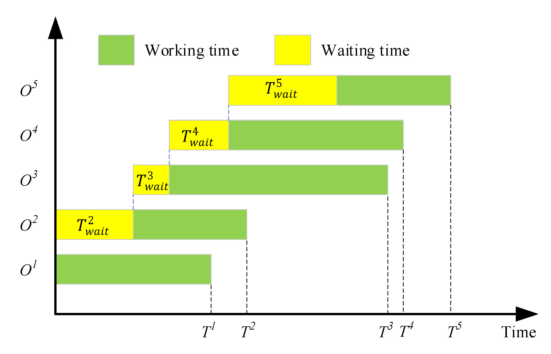
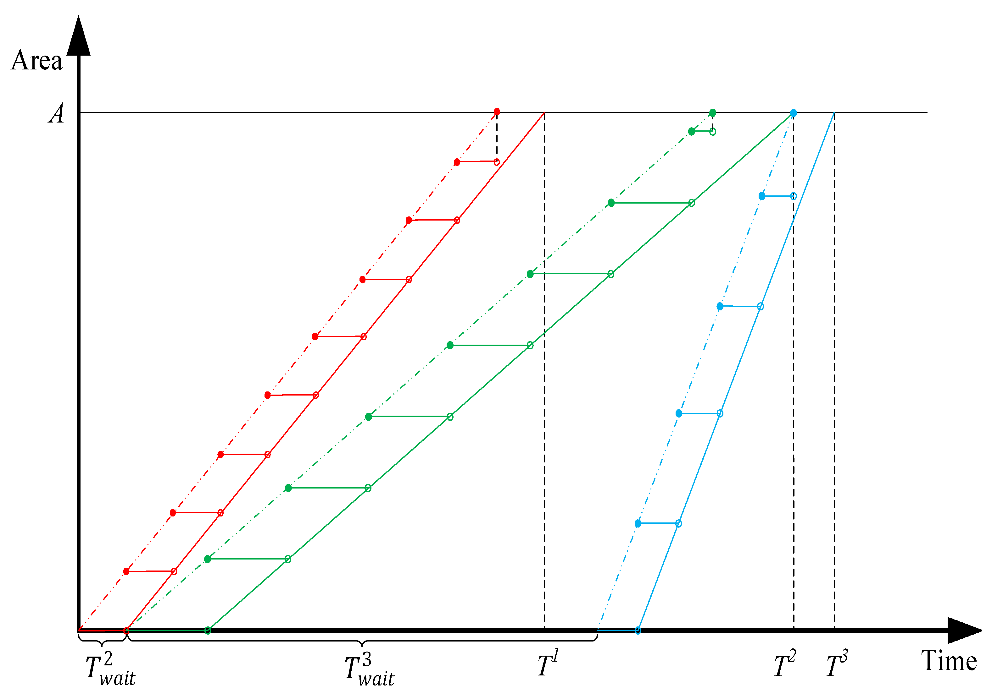
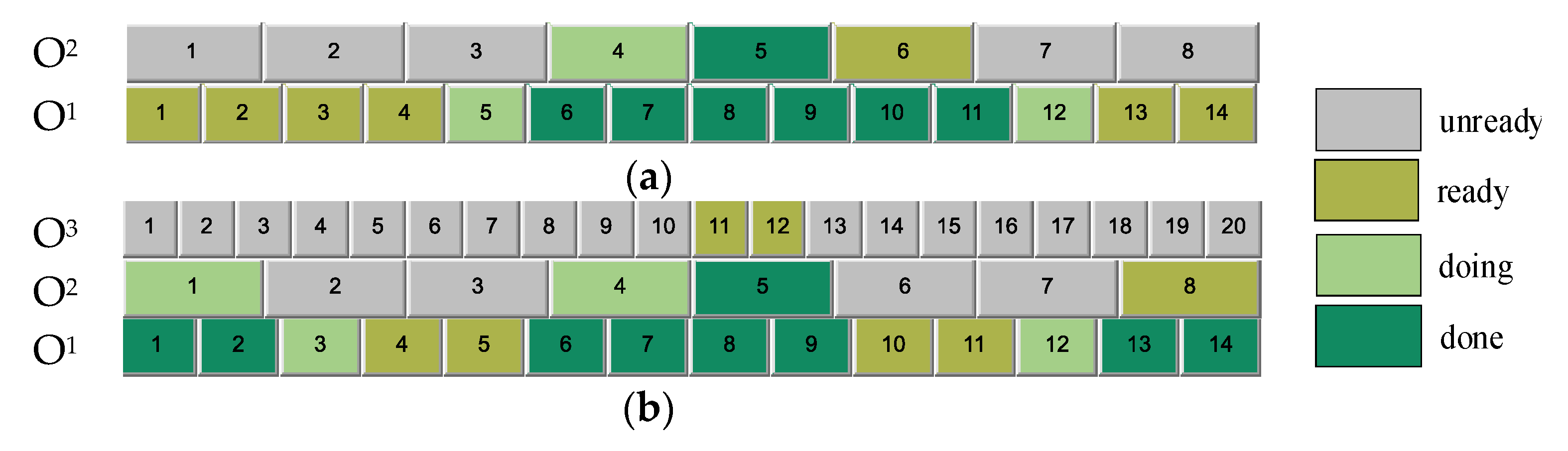
2.3.2. Operations Scheduling
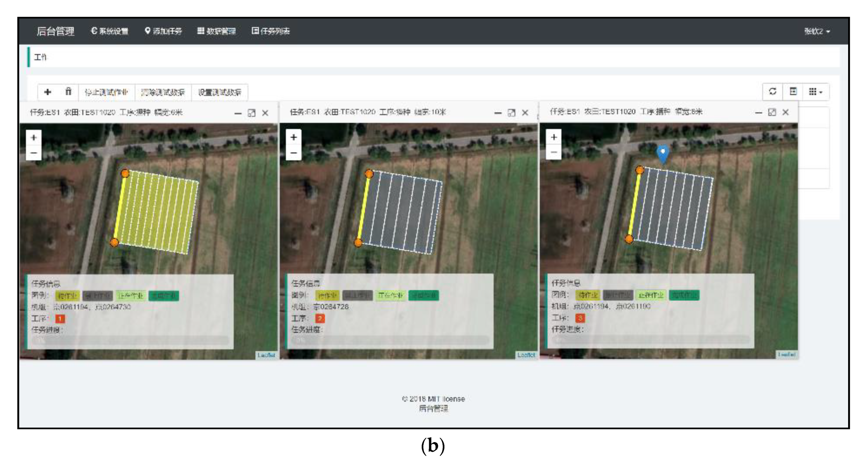
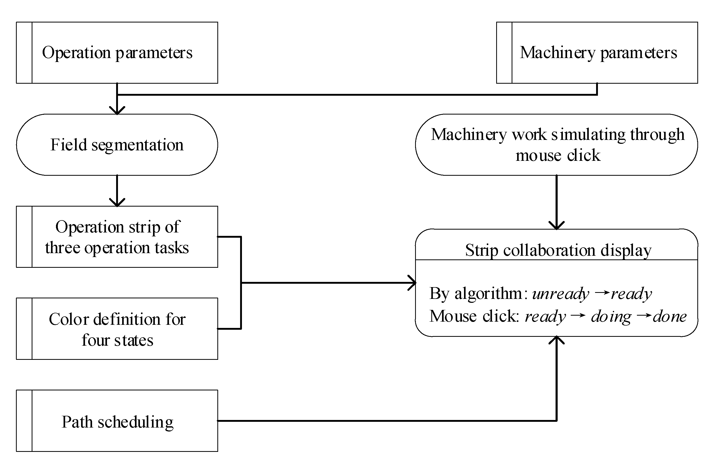
2.4. Collaborative Operating System
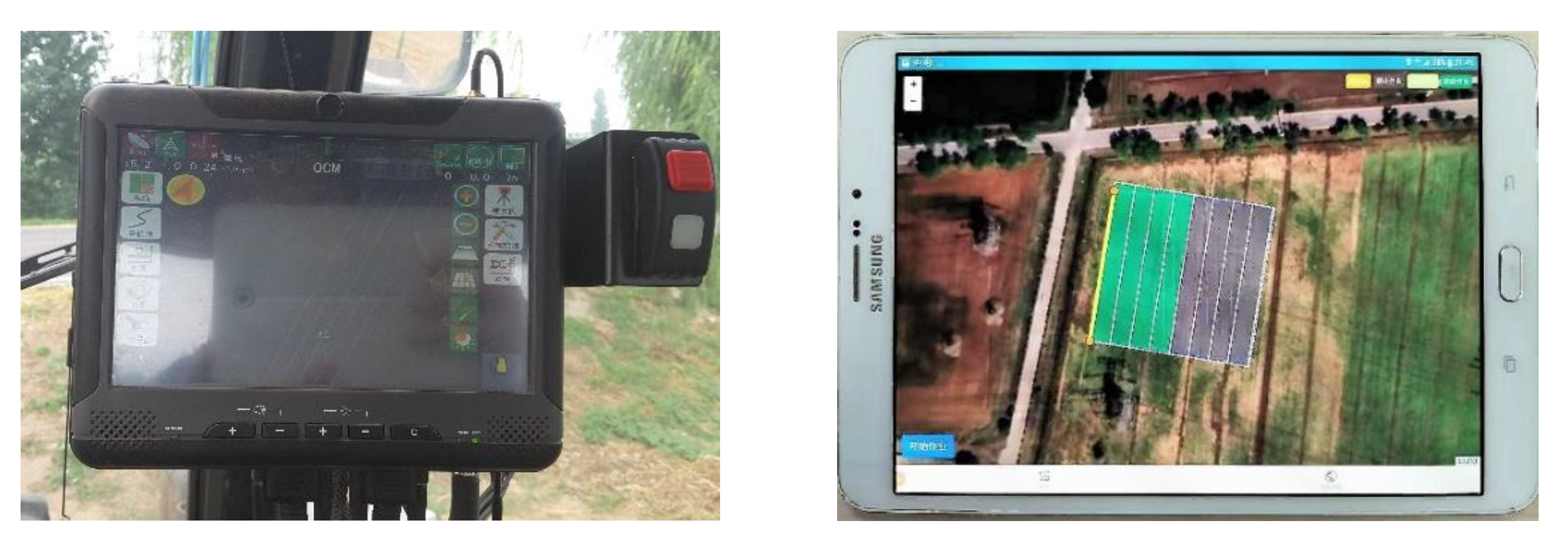
2.5. Auto-Steering System
3. Experiments
3.1. Simulation Experiments
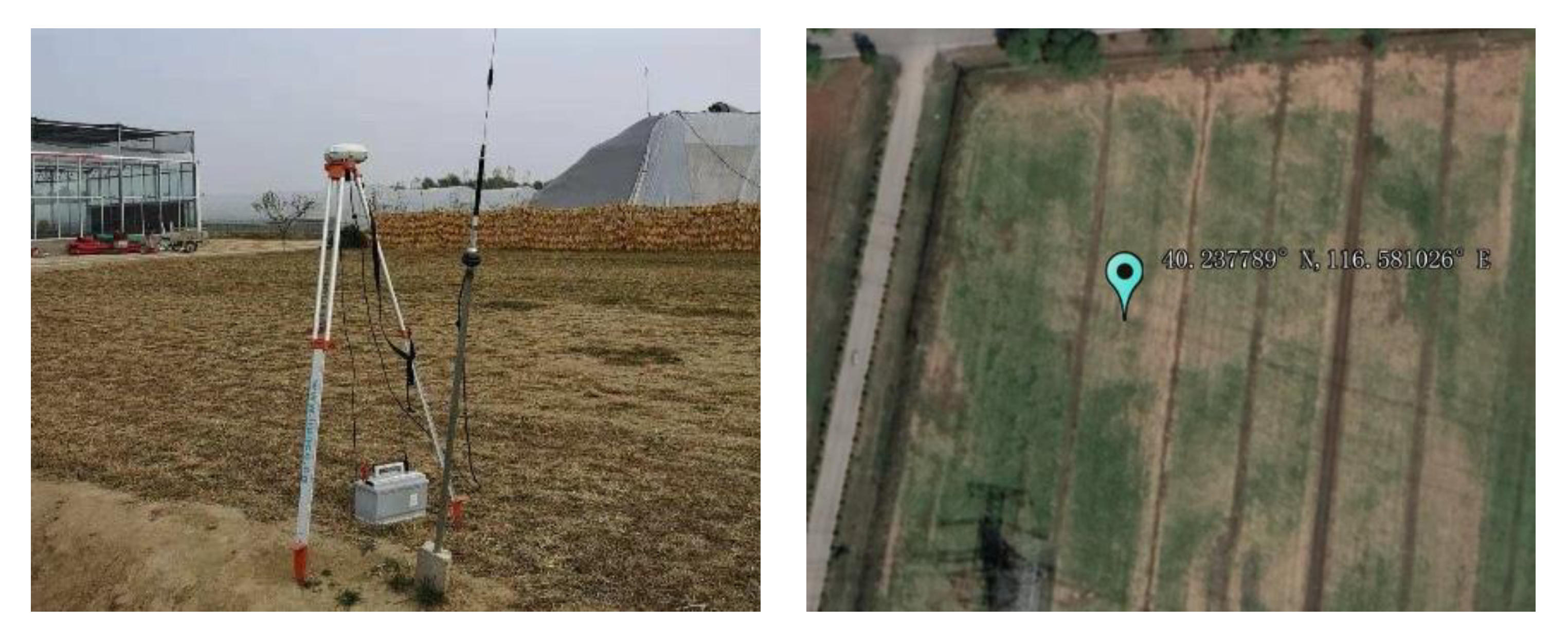
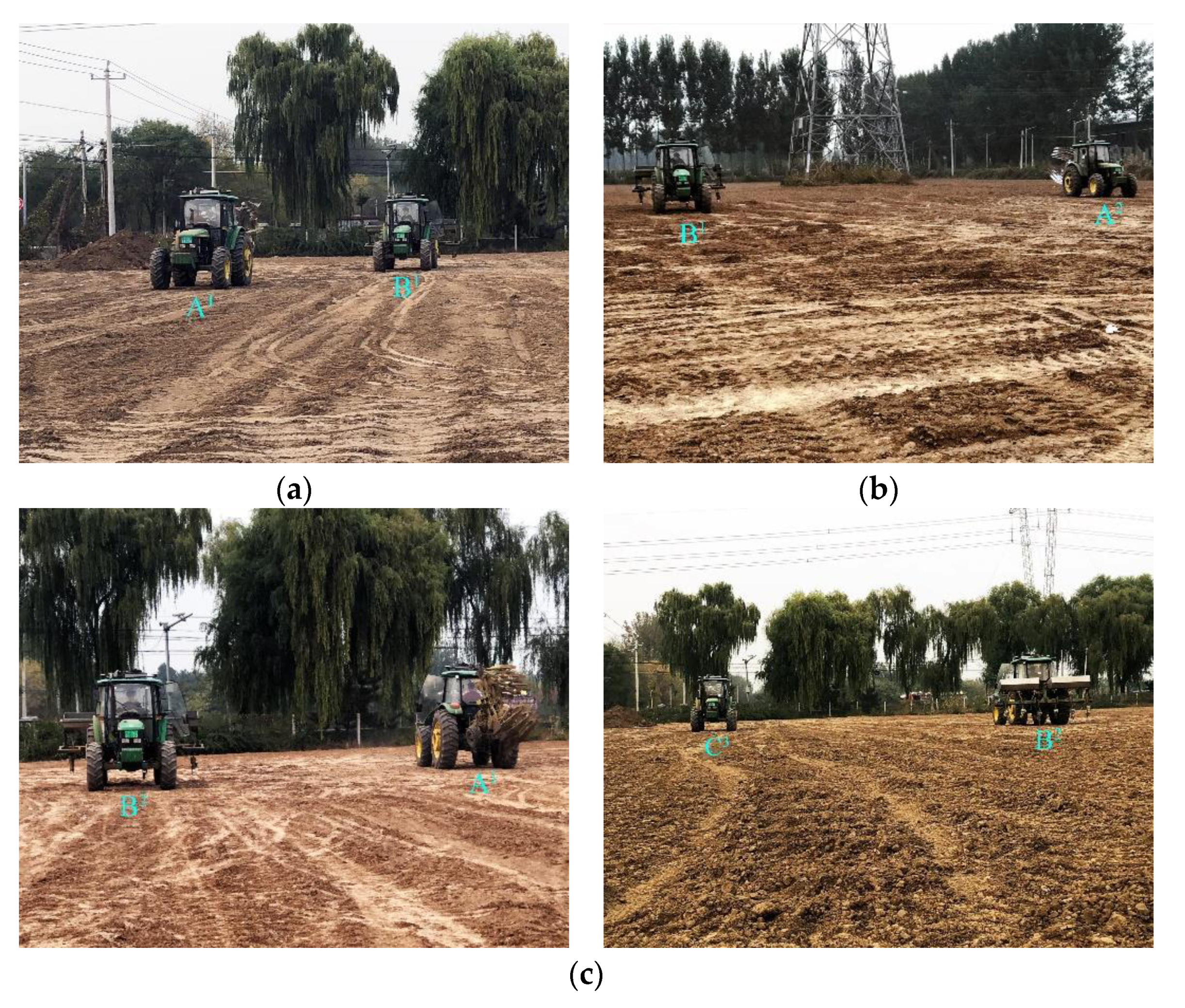
3.2. Field Experiments
3.3. Results and Discussion
3.3.1. Simulation Experiments
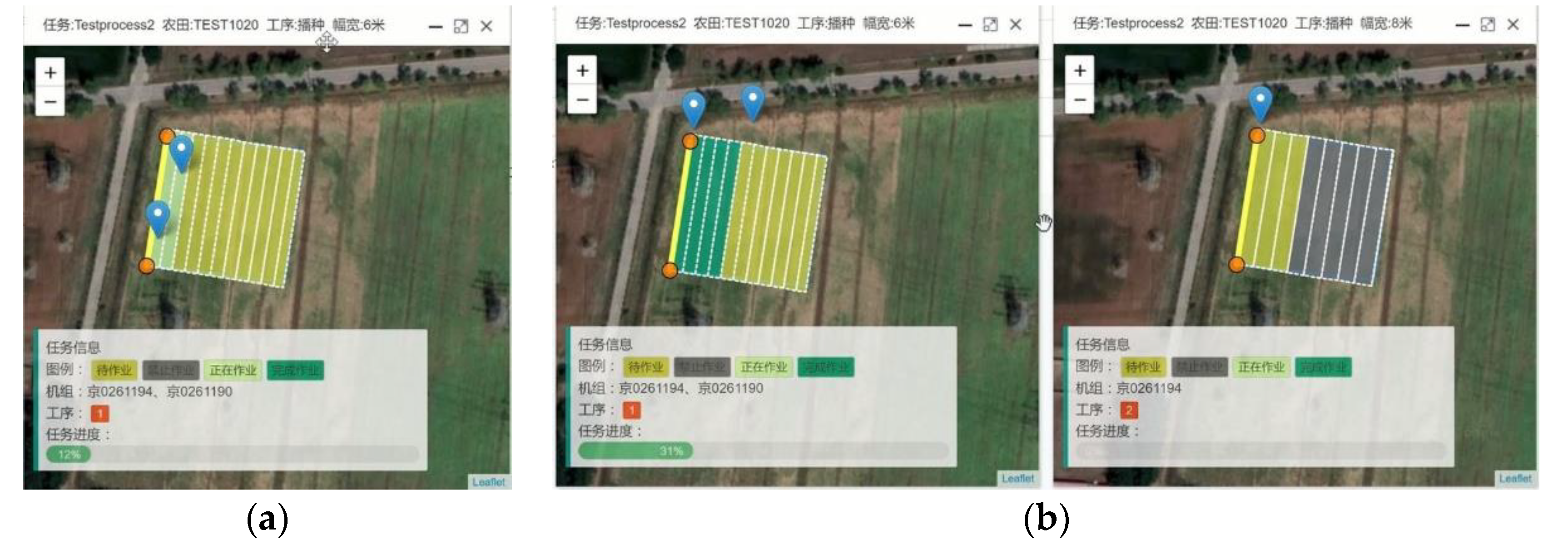
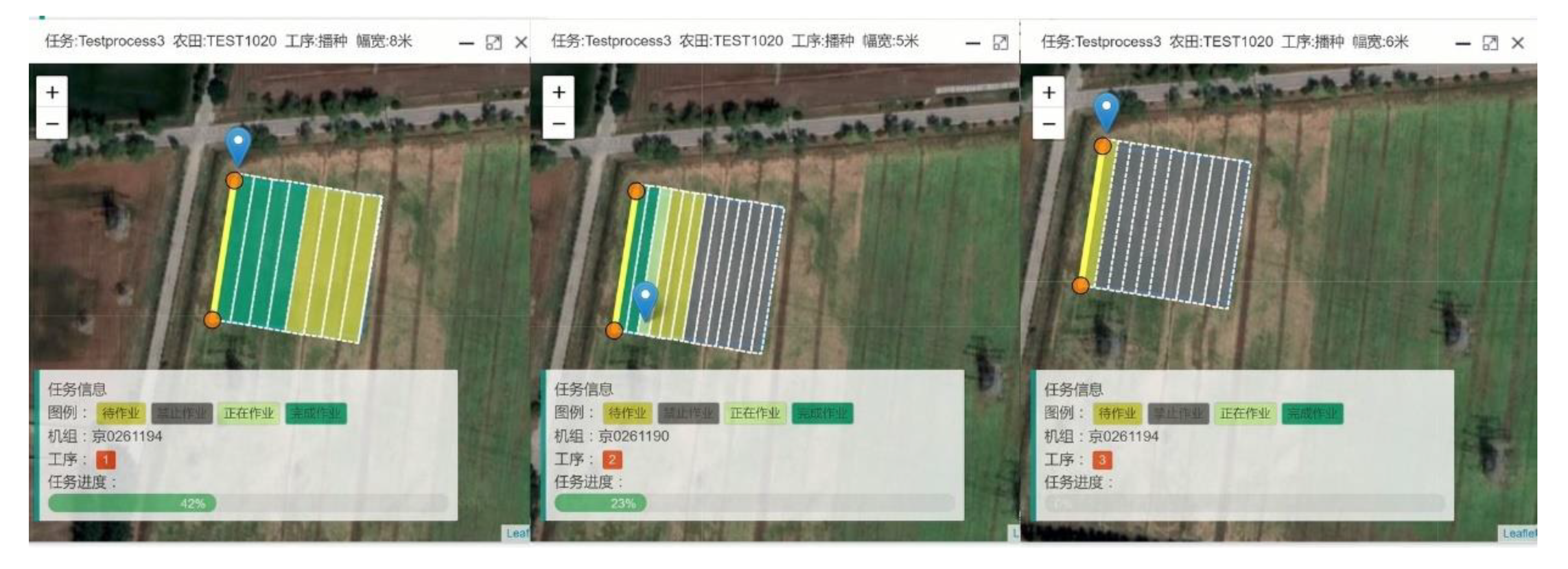
3.3.2. Field Experiments
4. Conclusions
Author Contributions
Funding
Conflicts of Interest
References
- Bsaybes, S.; Quilliot, A.; Wagler, A.K. Fleet management for autonomous vehicles: online PDP under special constraints. RAIRO Op. Res. 2019, 53, 1007–1031. [Google Scholar] [CrossRef] [Green Version]
- Wang, J.; Zhu, Y.; Chen, Z.; Yang, L.; Wu, C. Auto-steering based precise coordination method for in-field multi-operation of farm machinery. Int. J. Agric. Biol. Eng. 2018, 11, 174–181. [Google Scholar] [CrossRef] [Green Version]
- Srensen, C.G.; Bochtis, D.D. Conceptual Model of Fleet Management in Agriculture. Biosyst. Eng. 2010, 105, 41–50. [Google Scholar] [CrossRef]
- Wu, C.C.; Zhou, L.; Wang, J.; Cai, Y.P. Smartphone based precise monitoring method for farm operation. Int. J. Agric. Biol. Eng. 2016, 9, 111–121. [Google Scholar] [CrossRef]
- Noguchi, N.; Will, J.; Reid, J.; Zhang, Q. Development of a master-slave robot system for farm operations. Comput. Electron. Agric. 2004, 44, 1–19. [Google Scholar] [CrossRef]
- Haifeng, L.; Chaoyi, Z. Design and Simulation of a Master-slave Robot for Apple harvest. Adv. Mater. Res. 2013, 816, 1024–1027. [Google Scholar]
- Zhang, X.; Geimer, M.; Noack, P.O.; Grandl, L. Development of an intelligent master-slave system between agricultural vehicles. In Proceedings of the 2010 IEEE Intelligent Vehicles Symposium, San Diego, CA, USA, 24–24 June 2010; pp. 250–255. [Google Scholar]
- Zhang, C.; Noguchi, N.; Yang, L. Leader-follower system using two robot tractors to improve work efficiency. Comput. Electron. Agric. 2016, 121, 269–281. [Google Scholar] [CrossRef]
- Zhang, C.; Noguchi, N. Development of Leader-follower System for Field Work. In Proceedings of the 2015 IEEE/SICE International Symposium on System Integration (SII), Nagoya, Japan, 11–13 December 2015; pp. 364–368. [Google Scholar]
- Bai, X.; Wang, Z.; Hu, J.; Gao, L.; Xiong, F. Harvester Group Corporative Navigation Method Based on Leader-Follower Structure. Trans. Chin. Soc. Agric. Mach. 2017, 48, 14–21. [Google Scholar] [CrossRef]
- Zhou, K.; Jensen, A.L.; Bochtis, D.D.; Sorensen, C.G. Simulation model for the sequential in-field machinery operations in a potato production system. Comput. Electron. Agric. 2015, 116, 173–186. [Google Scholar] [CrossRef]
- Rodias, E.; Berruto, R.; Busato, P.; Bochtis, D.; Sorensen, C.G.; Zhou, K. Energy Savings from Optimised In-Field Route Planning for Agricultural Machinery. Sustainability 2017, 9, 1956. [Google Scholar] [CrossRef] [Green Version]
- Hameed, I.A.; Bochtis, D.; Sorensen, C.A. An Optimized Field Coverage Planning Approach for Navigation of Agricultural Robots in Fields Involving Obstacle Areas. Int. J. Adv. Robot. Syst. 2013, 10, 231. [Google Scholar] [CrossRef] [Green Version]
- Jensen, M.A.F.; Bochtis, D.; Sørensen, C.G.; Blas, M.R.; Lykkegaard, K.L. In-field and inter-field path planning for agricultural transport units. Comput. Ind. Eng. 2012, 63, 1054–1061. [Google Scholar] [CrossRef]
- Han, X.Z.; Kim, H.J.; Kim, J.Y.; Yi, S.Y.; Moon, H.C.; Kim, J.H.; Kim, Y.J. Path-tracking simulation and field tests for an auto-guidance tillage tractor for a paddy field. Comput. Electron. Agric. 2015, 112, 161–171. [Google Scholar] [CrossRef]
- Bochtis, D.D.; Dogoulis, P.; Busato, P.; Sorensen, C.G.; Berruto, R.; Gemtos, T. A flow-shop problem formulation of biomass handling operations scheduling. Comput. Electron. Agric. 2013, 91, 49–56. [Google Scholar] [CrossRef]
- Senlin, G.; Nakamura, M.; Shikanai, T.; Okazaki, T. Hybrid Petri Nets Modeling for Farm Work Flow. Comput. Electron. Agric. 2008, 62, 149–158. [Google Scholar] [CrossRef] [Green Version]
- Bai, X.; Hu, J.; Gao, L.; Li, T.; Liu, X. Self-tuning model control method for farm machine navigation. Trans. Chin. Soc. Agric. Mach. 2015, 46, 1–7. [Google Scholar] [CrossRef]
- Sadik, A.R.; Urban, B. Flow shop scheduling problem and solution in cooperative roboticscase-study: One cobot in cooperation with one worker. Future Internet 2017, 9, 48. [Google Scholar] [CrossRef] [Green Version]
- Wu, C.; Cai, Y.; Hu, B.; Wang, J. Classification and evaluation of uncertain influence factors for farm machinery service. Int. J. Agric. Biol. Eng. 2017, 10, 164–174. [Google Scholar] [CrossRef]
- Bechar, A.; Vigneault, C. Agricultural robots for field operations. Part 2: Operations and systems. Biosyst. Eng. 2017, 153, 110–128. [Google Scholar] [CrossRef]
- des Dorides, C. GNSS Market Report; European GNSS Agency: Luxembourg, 2017.
- Easterly, D.R.; Adamchuk, V.I.; Kocher, M.F.; Hoy, R.M. Using a vision sensor system for performance testing of satellite-based tractor auto-guidance. Comput. Electron. Agric. 2010, 72, 107–118. [Google Scholar] [CrossRef] [Green Version]
- Cao, R.; Li, S.; Wei, S.; Ji, Y.; Zhang, M.; Li, H. Remote Monitoring Platform for Multi-machine Cooperation Based on Web-GIS. Trans. Chin. Soc. Agric. Mach. 2017, 48, 52–57. [Google Scholar] [CrossRef]
- Deere, J. John Deere Machine Sync. Available online: https://www.deere.com/en_INT/products/equipment/agricultural_management_solutions/guidance_and_machine_control/machine_sync/machine_sync.page? (accessed on 24 November 2014).
- Jensen, M.F.; Bochtis, D.; Sorensen, C.G. Coverage planning for capacitated field operations, part II: Optimisation. Biosyst. Eng. 2015, 139, 149–164. [Google Scholar] [CrossRef]
- Wu, C.; Yuan, Y.; Han, Y. Application of Beidou in Agricultural Production Process; Song, M., Ed.; Publishing House of Electronics Industry: Beijing, China, 2016. [Google Scholar]
- Hunt, D. Farm Power and Machinery Management, 11th ed.; Waveland Press: Lake County, IL, USA, 2016; pp. 9–17. [Google Scholar]
- Zhou, K.; Jensen, A.L.; Bochtis, D.D.; Sorensen, C.G. Quantifying the benefits of alternative fieldwork patterns in a potato cultivation system. Comput. Electron. Agric. 2015, 119, 228–240. [Google Scholar] [CrossRef]


| State | Color | Value | Definition |
|---|---|---|---|
| unready |  | 0 | The strip is not ready for operation. |
| ready |  | 1 | The strip is ready for operation. |
| doing |  | 2 | The strip is being processed by a machine. |
| done |  | 3 | The strip has been processed by a machine. |
| Experiment Scheme | Operating Tasks | Machinery Arrangement * | Width of Strip/m |
|---|---|---|---|
| ES1 | One operation | A1 & B1 | 6 |
| ES2 | Two operations | A1 & B1 VS C2 | 6, 8 |
| ES3 | Three operations | A1 VS B2 VS C3 | 8, 5, 6 |
| Experiment | Machinery Arrangement | Operating Time [s] | Non-FMCOS 1 [s] | FMCOS 2 [s] | Efficiency Improvement 3 [%] | |
|---|---|---|---|---|---|---|
| ES1 | A1&B1 | A1 | 238 | 951 | 713 | 25.03 |
| B1 | 713 | |||||
| ES2 | A1&B1 | 713 | 1271 | 978 | 23.05 | |
| C2 | 558 | |||||
| ES3 | A1 | 485 | 1733 | 1166 | 32.72 | |
| B2 | 685 | |||||
| C3 | 563 | |||||
© 2020 by the authors. Licensee MDPI, Basel, Switzerland. This article is an open access article distributed under the terms and conditions of the Creative Commons Attribution (CC BY) license (http://creativecommons.org/licenses/by/4.0/).
Share and Cite
Wu, C.; Chen, Z.; Wang, D.; Song, B.; Liang, Y.; Yang, L.; Bochtis, D.D. A Cloud-Based In-Field Fleet Coordination System for Multiple Operations. Energies 2020, 13, 775. https://doi.org/10.3390/en13040775
Wu C, Chen Z, Wang D, Song B, Liang Y, Yang L, Bochtis DD. A Cloud-Based In-Field Fleet Coordination System for Multiple Operations. Energies. 2020; 13(4):775. https://doi.org/10.3390/en13040775
Chicago/Turabian StyleWu, Caicong, Zhibo Chen, Dongxu Wang, Bingbing Song, Yajie Liang, Lili Yang, and Dionysis D. Bochtis. 2020. "A Cloud-Based In-Field Fleet Coordination System for Multiple Operations" Energies 13, no. 4: 775. https://doi.org/10.3390/en13040775