Article

Effects of Temperature on the Flow and Heat Transfer in Gel Fuels: A Numerical Study

1
School of Mechanical Engineering, Nanjing University of Science & Technology, Nanjing 210094, Jiangsu, China
2
U.S. Department of Energy, National Energy Technology Laboratory (NETL), Pittsburgh, PA 15236, USA
*
Authors to whom correspondence should be addressed.
Energies 2020, 13(4), 821; https://doi.org/10.3390/en13040821
Submission received: 29 November 2019 / Revised: 29 December 2019 / Accepted: 12 February 2020 / Published: 13 February 2020

Abstract

:
In general, rheological properties of gelled fuels change dramatically when temperature changes. In this work, we investigate flow and heat transfer of water-gel in a straight pipe and a tapered injector for non-isothermal conditions, which mimic the situations when gelled fuels are used in propulsion systems. The gel-fluid is modeled as a non-Newtonian fluid, where the viscosity depends on the shear rate and the temperature; a correlation fitted with experimental data is used. For the fully developed flow in a straight pipe with heating, the mean apparent viscosity at the cross section when the temperature is high is only 44% of the case with low temperature; this indicates that it is feasible to control the viscosity of gel fuel by proper thermal design of pipes. For the flow in the typical tapered injector, larger temperature gradients along the radial direction results in a more obvious plug flow; that is, when the fuel is heated the viscosity near the wall is significantly reduced, but the effect is not obvious in the area far away from the wall. Therefore, for the case of the tapered injector, as the temperature of the heating wall increases, the mean apparent viscosity at the outlet decreases first and increases then due to the high viscosity plug formed near the channel center, which encourages further proper design of the injector in future. Furthermore, the layer of low viscosity near the walls plays a role similar to lubrication, thus the supply pressure of the transport system is significantly reduced; the pressure drop for high temperature is only 62% of that of low temperature. It should be noticed that for a propellent system the heating source is almost free; therefore, by introducing a proper thermal design of the transport system, the viscosity of the gelled fuel can be greatly reduced, thus reducing the power input to the supply pressure at a lower cost.

Graphical Abstract

1. Introduction

Gel fuels are promising candidates for certain future ramjet and rocket applications; they offer potential improvements in performance and/or safety over conventional liquid and solid propulsion systems [1]. In terms of safety and storage compared to liquid fuels, gel fuels are safer and can be stored much longer due to their stable internal structure. Meanwhile, gel fuels have high specific impulse and offer the possibility to build throttleable engines, which solid fuels is incomparable [2]. From a fluid mechanics point of view, gels behave as non-Newtonian fluids. Many fluids behaving non-Newtonian characteristics show shear-thinning viscosity, yield stress and thixotropy, respectively or simultaneously [3]. Gel fuels are made from liquid fuels with addition of particular gellants, which leads to the notable changes in the rheological properties of the fuels [3,4,5,6,7]. However, a shortcoming rises because of the addition of gellant. The higher level of viscosity of gel fuels compared with liquid fuels significantly reduces the efficiency of atomization and combustion [8,9,10].
Gels usually show a shear-thinning behavior, indicating that the viscosity decreases as the shear rate increases. This is an important issue for transporting of gel fuels in pipes. There are numerous mathematical models developed to describe the shear-thinning characteristic of fluids, for example, the power-law model and the Carreau type model [11,12,13]. Rahimi and Natan [14,15,16] numerically studied the flow of gel in straight and converging pipes using the power-law model. Some basic parameters such as the velocity, the viscosity and the pressure drop were obtained. The distribution and variation of these parameters were analyzed by changing the geometries. Bo and Mengzheng [17] studied the flow and the rheological characteristics of gels in a pipe by using POLYFLOW software. The result showed that the pressure loss reduces rapidly when the diameter increases, keeping the velocity and the pipe length constant. Meanwhile, a plug flow exists near the central axes area, especially when the power law index increase. The Carreau–Yasuda model was used by Yoon et al. [18] to described the constitutive relationship of water-HPC (hydroxypropylcellulose) gel. They found that the increase of the length-diameter ratio and the convergence angle of the injector is beneficial to decreasing the viscosity at the outlet. Cao et al. [19] measured the rheological parameters of water-HPC gel and fitted the model parameters of the Carreau–Yasuda model. Their numerical results of the gel fuel in tapered injectors suggests that a compromise should be achieved between the pressure loss and the viscosity reduction for a better design and engineering operation.
On the other hand, temperature changes also play a role in the rheological properties of gel. Shin and Cho [20] investigated the effect of the temperature-dependent and the shear-thinning viscosity on the laminar flow and heat transfer of a non-Newtonian fluid in a duct. In their study, they combined the Arrhenius and power-law models to describe the influence of the shear rate and the temperature on the viscosity; their results show excellent agreement with the experimental data. Varghese et al. [21] found that temperature affect the yield stress of virgin and metallized UDMH gels. Rahimi et al. [22] and Rahimi and Natan [23] investigated the effect of temperature on the parameters in the power-law model, namely the consistency index K and the exponent n, for various gellant fraction, where the parameters K and n were expressed as functions of temperature and the gellant fraction. Ellahi [24] examined the magnetohydrodynamic (MHD) flow of non-Newtonian nanofluids in a pipe with two different temperature dependent viscosity models, namely the Reynolds’ model and the Vogel’s model. A strong dependence of the velocity and temperature profiles on the viscosity was noticed in the simulation. Fu et al. [25] studied the steady shear flow of a power-law gel using a Bohlin cone-and-plate controlled stress rotational rheometer. The results show that the model parameter, K, decreases as the temperature increases. Moreover, it was also noticed the parameter, n, generally increases as the temperature increases. In general, the effect of the temperature is different for different kinds of gels. Jyoti et al. [26] measured the apparent viscosity of the ethanolamine gel with the PVP   +   SiO 2 hybrid gelling agent at different temperatures. They notice that the apparent viscosity initially increases and then decreases with the increase in the temperature.
According to our knowledge, numerical investigations on the flow and heat transfer of gel fuels showing shear-thinning and temperature sensitive viscosity, has not been reported yet. In this paper, we conduct a numerical study about the flow and heat transfer characteristics of a non-Newtonian gel in two problems, which are the typical geometries used in fuel-delivery propulsion systems. In Section 2, we discuss our mathematical approach, by presenting the governing and constitutive relations. The dimensionless forms of the equations are also presented. In Section 3, we present the geometry of the two problems and then a brief discussion of the boundary conditions and mesh study. In Section 4, we present the results.

2. Methods

2.1. Mathematical Approach

We consider the gel-fluid as a non-linear fluid, where the shear viscosity is assumed to depend on the shear rate and the temperature. The governing equations for a single-phase fluid are the conservation equations for mass, linear momentum, and the energy equation, as shown below (see Chapter 3 of [27]). The variation of the density of the fluid due to the temperature changes is ignored and the fluid is considered to be incompressible.

2.1.1. Governing Equations

Conservation of Mass:

For an incompressible fluid [28], the conservation of mass is simplified to,
d i v   v = 0
where v is the velocity vector, and ‘ d i v ’ is the divergence operator.

Conservation of Momentum:

The conservation of linear momentum is [27,29],
ρ d v d t = d i v T + ρ b
where T is the Cauchy stress tensor, d / d t is the total time derivative given by d ( . ) /   d t = ( . )   / t + v · [ g r a d ( . ) ] , where ‘grad’ is the gradient operator and b is the body force (ignored in this paper). The conservation of angular momentum indicates that in the absence of couple stresses the stress tensor is symmetric, i.e., T = T T .

Conservation of Energy:

The conservation of energy reads,
d e d t = T : L d i v   q + ρ r
where e is the internal energy density, ‘ : ’ designates the scalar product of two tensors, L is the gradient of velocity, q is the heat flux vector, and r is the specific radiant energy which will be neglected in this study. In the above equation, T : L represents the viscous dissipation and d i v   q represent the heat conduction. Constitutive relations are needed for T ,   e and q in order to ‘close’ the above equations.

2.1.2. Constitutive Equation for the Stress Tensor and Heat Flux Vector

Stress Tensor:

Roscoe [30] provided a thorough review of modeling and characterizing gel-like materials. In general, gels behave as non-Newtonian fluids (NNF). Non-Newtonian (non-linear) fluids exhibit some unusual characteristics. For example, some NNF’s show normal stress effects, as manifested in phenomena such as die-swell or rod-climbing (see Chapter 7 of the book by Schowalter [31]). Some non-Newtonian fluids have yield stress or show viscoelastic effects, while some have viscosities which depend on shear rate and temperature or even pressure (see Chapter 1 of the books by Macosko [32]); Chapter 2 of the book by Carreau, De Kee and Chhabra [33]). Perhaps the simplest model, from an engineering perspective, which can capture the shear-thinning (or shear-thickening) effect, is the power-law model. In this paper, we consider the dependence of the viscosity of the water-gel on the shear rate and the temperature. We assume that the stress tensor of the water-gel is given by the power-law model,
T = p I + 2 η D
Here η is the shear viscosity of the water-gel (which depends on the shear rate and the temperature), I is the identity tensor, p is the pressure and D is the symmetric part of the velocity gradient. According to the literature [14,34], the water-gel can usually be modeled as a power-law fluid. Thus, we assume
η ( T , γ ˙ ) = η T ( T ) · η γ ˙ ( γ ˙ )
where we assume
η γ ˙ ( γ ˙ ) = K 1 γ ˙ n 1
which is the traditional power-law formulation, and for η T ( T ) we assume
η T ( T ) = K 2 e x p a T
If we combine these two equations, we obtain [35]:
η ( T , γ ˙ ) = K γ ˙ n 1 e x p a T
where T is the temperature, γ ˙ is the shear rate (which is γ ˙ = 2 t r D 2 ), ‘ t r ’ designates the trace of a tensor, K is the consistency index, and n is the power-law exponent, indicating the intensity of the shear rate dependency; when n < 1 , the fluid is shear-thinning, when n > 1 the fluid is shear-thickening, and when n = 1 the fluid behaves as a Newtonian fluid, a is the temperature index. Note that other useful correlations for the temperature-dependent viscosity are the Reynolds equation and the Vogel equation (see Massoudi and Christie [36]). In Section 2.2, the model parameters in Equation (8) will be fitted to experimental measurement. Thus,
T = p I + 2 K γ ˙ n 1 e x p a T D
We use this equation for the stress tensor T in our numerical analysis.

Internal Energy:

In general, the internal energy density is given by,
e = ρ ε
where ε is assumed to be [27],
ε = C p T
where C p is the heat capacity of the fluid, which is assumed to be constant.

Heat Flux Vector:

The classical theory of heat conduction states that the heat flux vector is related to the temperature gradient [37], where
q = k g r a d T
where k is the thermal conductivity of the fluid. For complex materials, k can depend on the concentration, the temperature, the shear rate, magnetic field (see Massoudi [38,39]). In general, if the material is anisotropic, it would depend on the direction of the fibers, for example, and in these cases, the thermal conductivity is given by a second order tensor K (or K i j in a Cartesian system) with nine different components. In this paper, we assume that the water-gel is isotropic and has a constant thermal conductivity. According to experimental measurements [40], the variation of the thermal conductivity of the water-gel is moderate when changing the weight fraction of the gallant; therefore, we assume that the value of k is the same as the thermal conductivity of water.

2.1.3. Expanded Form of the Governing Equations

Using Equations (4) and (8) in Equation (2), we obtain a set of partial differential equations (PDEs) which need to be solved numerically. To obtain numerical solutions to these equations, we build our PDEs solver using the libraries provided by OpenFOAM [41]. The dimensionless form of these PDEs are given below:
d i v V = 0
V τ + V · ( g r a d   V ) = g r a d   P + 1 R e d i v ( η ( θ , γ ˙ ) η r D )
θ τ + V · ( g r a d   θ ) = D s η ( θ , γ ˙ ) η r D : L + L e ( d i v   ( g r a d   θ ) )
where we have used the following non-dimensional parameters:
Y = y L r ;   X = x L r ;   V = v v 0 ; τ = t v 0 L r ; θ = T T 0 T 1 T 0 ; Γ ˙ = γ ˙ γ r ˙ ; Η = η η r
P = p ρ v 0 2 ; R e = ρ L r v 0 η r ; D s = η r v 0 ρ C p ( T 1 T 0 ) L r ; L e =   k ρ C p v 0 L r ;  
div ( ) = L r div ( ) ;   grad ( ) = L r grad ( ) ;   D = 1 2 [ grad V + ( grad V ) T ] ;
where L r is a reference length, v 0 is a reference velocity, T 1 and T 0 are reference temperatures and are set as 372 K and 298 K in this paper, η r is the reference viscosity and R e is the Reynolds number. D s is the dimensionless number related to the viscous dissipation and L e is the Lewis number which is the ratio of thermal diffusivity to convective mass transport. The asterisks have been dropped for simplicity. In the next section, we will discuss the experimental setup. To characterize the flow behavior of non-Newtonian fluids of the power-law type, we use a generalized Reynolds number given by [42,43],
R e g e n = ρ v 0 2 n d n K e x p a T ( 0.75 + 0.25 n ) n × 8 n 1

2.2. Parameters in the Constitutive Equation for the Stress Tensor

Figure 1 shows the measured viscosity [44] and the theoretical predictions for different temperatures and shear rates. In this figure, the symbols are used for the experimental measurements [44], while the solid lines (curves) represent the prediction by Equation (8) with K = 167.7978   Pa · s n ,   n = 0.4751 , a = 1.116 × 10 2   1 / K . In our constitutive equation, we have considered both the effects of the shear rate and the temperature. The influence of the temperature on the rheological properties of water-gel is usually investigated in two ways: (1) obtain the flow curves at constant temperature for various share rates and (2) apply a constant shear rate while temperature is changed with time. The experimental data was obtained using the second method [44].

3. Problem Descriptions

We study two different problems: (1) flow and heat transfer of water-gel in a straight pipe and (2) flow in a tapered injector which mimics the flow of gelled fuels in propulsion systems, see Figure 2. The radius of the straight pipe is R , and the length of the pipe L = 8 R . For the tapered injector, the radius of the front tube is R i . We set a long straight pipe in the front of injector to ensure a fully developed flow before flowing through the heated region. The heated walls are indicated by the red lines shown in Figure 2b and L i = L o = R i . The diameter of the straight part after the converging region is R o = 0.25 R i , and the convergence angle is α = 45 ° . For both cases, we have taken advantage of the symmetry of the problem.
The boundary conditions are listed in Table 1. In the case of flow in the straight pipe, we consider the effect of different wall temperatures. To better understand the fully developed and steady-state flow, a periodic boundary condition is applied at the inlet and the outlet. In OpenFOAM, the periodic boundary condition is incorporated by setting the inlet and the outlet as “cyclic” boundaries, which enables these two boundary to be treated as if they are physically connected, for more details see page 145 of [45]. In the case of the tapered injector, we consider different wall temperatures (or heat fluxes), Reynolds number and different heated locations. To ensure safety-related issues and that the results are useful for real situations, the temperature is kept below the boiling point.
To make a better analysis of the effects of the flow conditions, a mean apparent viscosity (integrated across the cross section) is defined as [19]:
η ¯ = 1 R 2 2 η r d r
The mean velocity, the mean pressure and the mean shear rate at any cross-section are also calculated in a similar way. For both geometries, a mesh dependency study is performed. Here we only show the results for the tapered injector in Table 2, where three meshes are studied, with R e g e n = 0.1 . The mean apparent viscosity at the outlet of the injector is calculated. As a result, grid B is chosen.

4. Results and Discussion

4.1. Straight Pipe

The velocity, shear rate and apparent viscosity distribution of the gel in the straight pipe are shown in Figure 3. The wall temperature is θ w = 1 and the inlet R e g e n is 0.1. In this study, the mean velocity, the mean shear rate and the mean apparent viscosity of the cross-section are chosen as the reference values, respectively. V is the ratio of the local velocity in the pipe to the mean inlet velocity, Γ ˙ is the dimensionless shear rate, and Η is the dimensionless apparent viscosity, see Equation (16) for the expressions. Because of the adoption of the periodic boundary condition, the temperature for the fully developed flow is equal to the wall temperature, therefore the gel behaves as a power-law fluid. At the walls, the shear rate reaches the maximum value, and as a shear-thinning fluid the gel has its lowest apparent viscosity there.
We first study the influence of different wall temperatures, when R e g e n equals to 0.1. The fully developed velocity, shear rate and apparent viscosity profiles at different cross-sections with different wall temperatures are shown in Figure 4. It can be seen that the gel velocity distribution is exactly the same for these different temperatures. Compared with the Newtonian fluid, near the axis of the pipe the velocity profile is blunter; according to Equation (8), the parameter, n , is a measure of the intensity of the shear rate dependency. Thus, we can see that changing n significantly affects the apparent viscosity of the gel, which further leads to the variation of the velocity distribution [46]. The smaller the value of n , the larger is the value of the velocity at the centerline.
Figure 4c indicates that the change of temperature has a great effect on the apparent viscosity. The higher the temperature, the lower the apparent viscosity at each point on the cross-section. Figure 5 shows the mean apparent viscosity for different wall temperatures, where we can see that the mean apparent viscosity at θ w = 1 is only 44% of the case with θ w = 0 . It is clear that raising the temperature significantly reduces the apparent viscosity of the gel. This is important since for a gel-fuel propulsion system the viscosity reduction is a key point for achieving better spray atomization and lower transport cost.

4.2. Tapered Injector

In this section, we study the necessary components in liquid propulsion systems, namely, the tapered injector. The mean inlet velocity for each case is chosen as the reference velocity; the mean inlet shear rate and mean inlet apparent viscosity at θ w = 1 and R e g e n = 0.023 are the reference shear rate and reference apparent viscosity. We first investigate the effect of the walls heating on the flow field. Figure 6 shows the contours of different flow fields when the dimensionless wall temperature ( θ w ) is 0 and 1. The dimensionless inlet temperature ( θ i n ) is 0 and the R e g e n is 0.023. From Figure 6 we can see that the maximum velocity in the injector is lower if the walls are heated. Another feature is that when θ w = 1 , the apparent viscosity of the gel at the inlet is greater than when θ w = 0 , which may be due to the lubrication layer in the low viscosity region (high shear rate) formed near the walls due to the heating effect.
Figure 7a shows the dimensionless temperature profiles in the radial direction at the outlet for different wall temperatures. Due to the heating of the walls, the temperature gradually increases in the radial direction; while for all cases the temperature at the centerline is not affected. This can be attributed to the convection being larger than the thermal diffusion. Figure 7b indicates that the wall temperature affects the velocity distribution; specifically, when the wall temperature increases, the velocity profile becomes blunter, indicating a plug flow. Figure 7c shows the dimensionless shear rate profiles for different wall temperatures. The local shear rate near the walls increases as the wall temperature increases. For other locations along the pipe, a higher temperature at the walls leads to a lower local shear rate. Figure 7d plots the dimensionless apparent viscosity in the radial direction at the outlet for different wall temperatures. The apparent viscosity of the gel near the wall with higher wall temperature is significantly lower, because of both the high shear rate and the high temperature. Near the centerline, the gel temperature is hardly affected by changes in θ w , see Figure 7a; therefore the apparent viscosity is only affected by the shear rate exhibiting the classic power-law relationship.
In conventional liquid fuel systems, most researchers focus on ways of reducing the pressure drop to reduce the required pumping power. For transport of gel fuels, we should also reduce the apparent viscosity in order to achieve more efficient and better spray atomization and combustion. Figure 8 shows the pressure drop and the mean apparent viscosity at the outlet for different wall temperatures. We can see that heating the walls significantly reduces the pressure drop, see the reduction of the viscosity at the walls in Figure 7d as well. The dimensionless pressure drop when θ w = 1 is only 62% of the case when compared to the case when θ w = 0 . The mean apparent viscosity at the outlet decreases first and then increases when the wall temperature increases. It can also be noticed from Figure 7d that the apparent viscosity increases with higher wall temperatures in the region of 0.1 < r / R o < 0.7 . We think this is attributed to the formation of a lubrication layer of low viscosity (high shear rate, high velocity) near the walls due to the heating effect. It is noticed that the mean apparent viscosity does not change monotonously when the wall temperature increases; in this case, the minimum mean apparent viscosity is obtained when θ w = 0.3 .
In practical propellant systems, there are two potential methods that can be applied to heat the gel fuel: one is through the introduction of a high temperature airflow, which can be achieved as a boundary condition at the walls; another is by using electrical heating, which can be modeled as a constant heat flux boundary condition. Here, we will consider the flow characteristics in the tapered injector with a constant heat flux boundary condition. The contours of the temperature, velocity, shear rate and apparent viscosity with a constant dimensionless heat flux of 1.08 are shown in Figure 9. The dimensionless inlet temperature is 0 and the R e g e n is 2.3 × 10 2 . The maximum temperature occurs at the corner of the inlet in the convergent section of the injector. Figure 10 shows the pressure drop and the mean apparent viscosity at the outlet with different values for the heat flux. Similar to the situations with constant wall temperature, as the heat flux at the wall increases, the pressure drop behaves in a linear fashion, while the mean apparent viscosity decreases quickly at first and then increases a little after ϕ p reaches 0.4.
Figure 11 shows the dimensionless temperature, velocity, shear rate and apparent viscosity profiles in the radial direction for different R e g e n . Under isothermal conditions, for a shear-thinning gel, larger values of R e g e n lead to larger shear rates and lower apparent viscosity, but a greater pressure supply is required [19]. Figure 11a shows the temperature distribution in the radial direction at the outlet of the injector for different R e g e n . It can be seen that the lower the R e g e n , the higher the depth of the penetration of the heat transfer. Figure 11b indicates that as R e g e n increases, the velocity profiles become blunter. It can also be seen in Figure 11c that higher values of R e g e n lead to higher shear rates in all regions at any cross-section. For the isothermal situation, we expect a viscosity reduction in all regions as a result; however Figure 11d shows that there are regions with lower apparent viscosity for smaller values of R e g e n due to the effect of the temperature. Therefore, the shear rate and the temperature have competing effects on the distribution of the apparent viscosity. The effect of R e g e n on the pressure drop and the mean outlet apparent viscosity when the walls are heated is represented in Figure 12. As the R e g e n increases, the mean apparent viscosity decreases while the pressure drop increases. Therefore, an appropriate R e g e n should be chosen depending on the practical requirements of the propellant system.
A typical tapered injector geometry is generally composed of three sections: the upstream isometric section, the convergent section and the downstream section. In order to study the effects of the heating, we heat only one section position. In Case a, Case b and Case c, the walls of the isometric section, the convergent section and the downstream section are heated (kept) at a constant temperature,   θ w = 1 , where the R e g e n at the inlet is 2.3 × 10 2 , and the dimensionless temperature at the inlet is θ i n = 0 . The high temperature contour near the walls in Figure 13 shows the heating position for these different cases. In the downstream section, the velocity near the axis of Case c is lower than others, which implies a blunter velocity distribution there. In Case a, the apparent viscosity near the axis of the upstream isometric section is greater, which can be attributed to the formation of the lubrication layer near the heating wall in this section.
Figure 14a shows the dimensionless temperature profiles in the radial direction at the outlet for different heating position. The penetration of heat transfer is the strongest for Case a, because it is the farthest away from the outlet; furthermore, because for all cases the total heat transferred into the system is similar, Case a has the lowest near-wall temperature at the outlet. Figure 14b indicates that Case c has a blunter temperature profile corresponding to the observation in Figure 13c. Combining the numerical observations above, we can find that a greater temperature gradient in the radial direction usually leads to a blunter velocity profile. Figure 14d indicates that the apparent viscosity near the central axis almost exactly follows the pattern of the power-law model under the effect of local shear rate (see Figure 14c), because of the isothermal condition there (see Figure 14a); near the wall the behavior of the apparent viscosity is more complex due to the mixed effects of the shear rate and the temperature.
The pressure drop and the mean apparent viscosity at the outlet for heated, partially heated and nonheated walls are listed in Table 3. When the whole injector is heated, the pressure drop is the smallest, while the mean apparent viscosity is larger than that of the nonheated condition. Comparing the three partially heated cases, the mean apparent viscosity is the smallest when heating is applied at the isometric section, while the pressure drop is the smallest when heating is applied at the downstream section. From the table, we can see that the wall heating significantly reduces the pressure drop. However, the effect of the wall heating on the apparent viscosity is not significant; we believe this is attributed to the formation of the near-wall lubrication layer of low apparent viscosity, which suppresses the penetration of the heat transfer into the main flow.

5. Conclusions

In this paper, we have studied the flow and heat transfer characteristics of water-gel fuel in a straight pipe and a tapered injector mimicking the flow of gelled fuels in propulsion systems. The viscosity of the water-gel is assumed to depend on the shear rate and the temperature; the model parameters are fitted with the available experimental data by using the power-law model. Through the numerical simulations, we can draw the following conclusions:
(a)
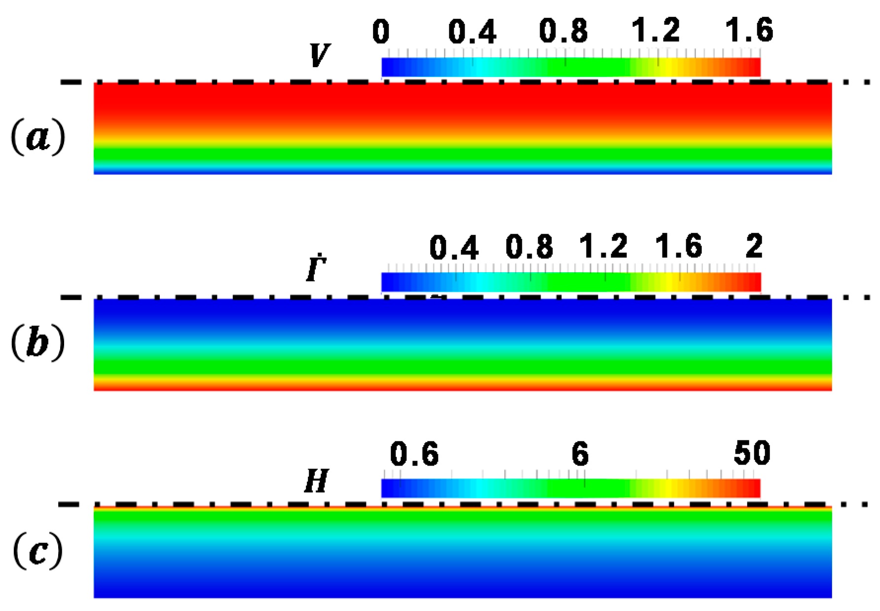
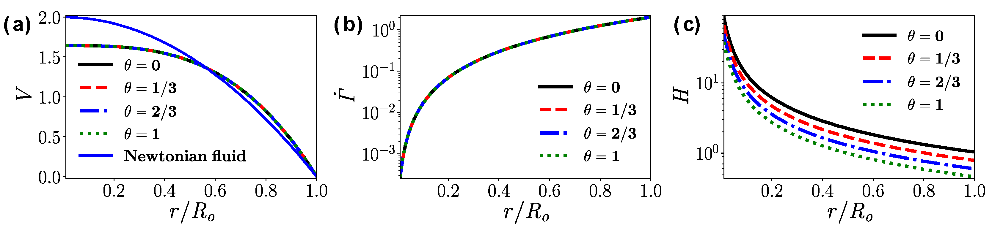
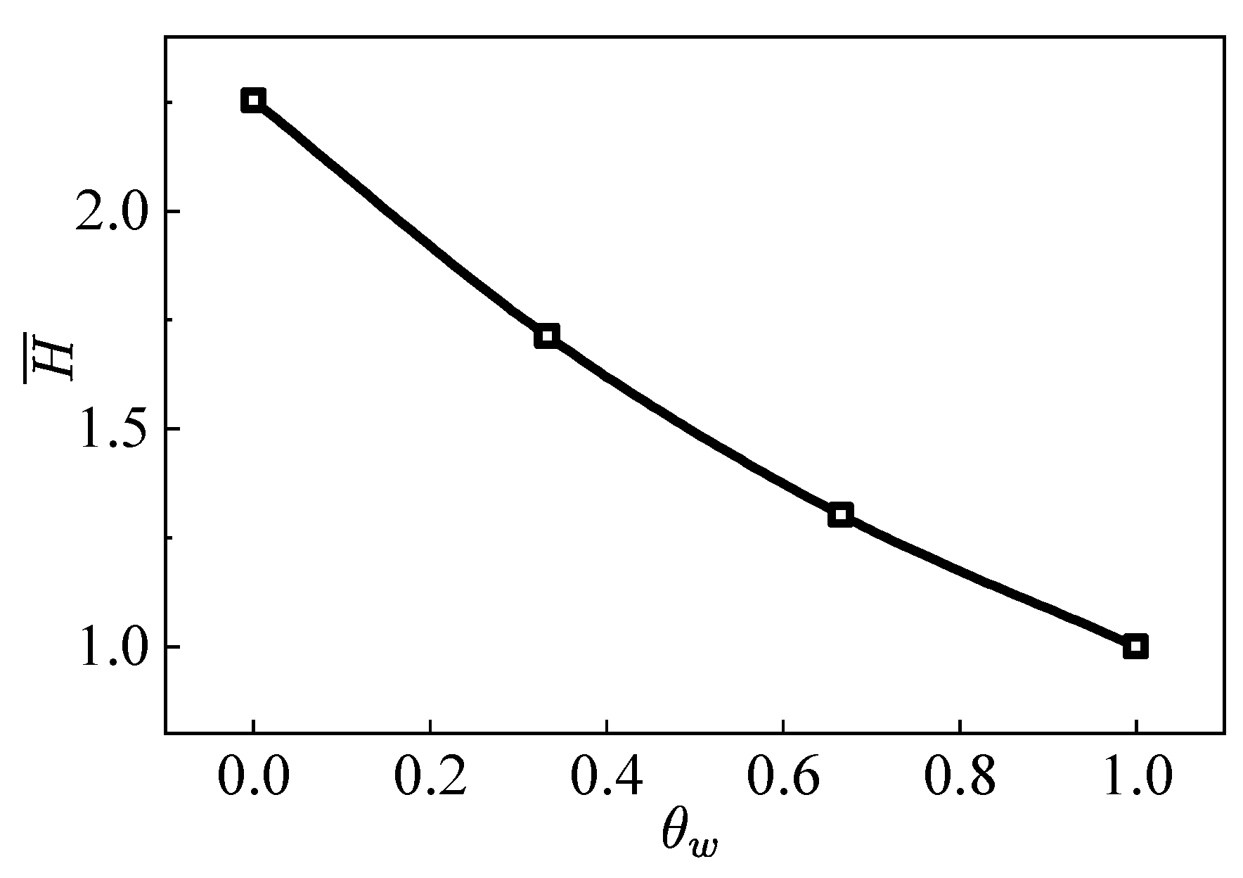
For the fully developed flow in the straight pipe, the apparent viscosity decreases significantly with the increase of the wall temperature. For the simulation reported here, the mean apparent viscosity when θ w = 1 is only 44% of the case when θ w = 0 .
(b)
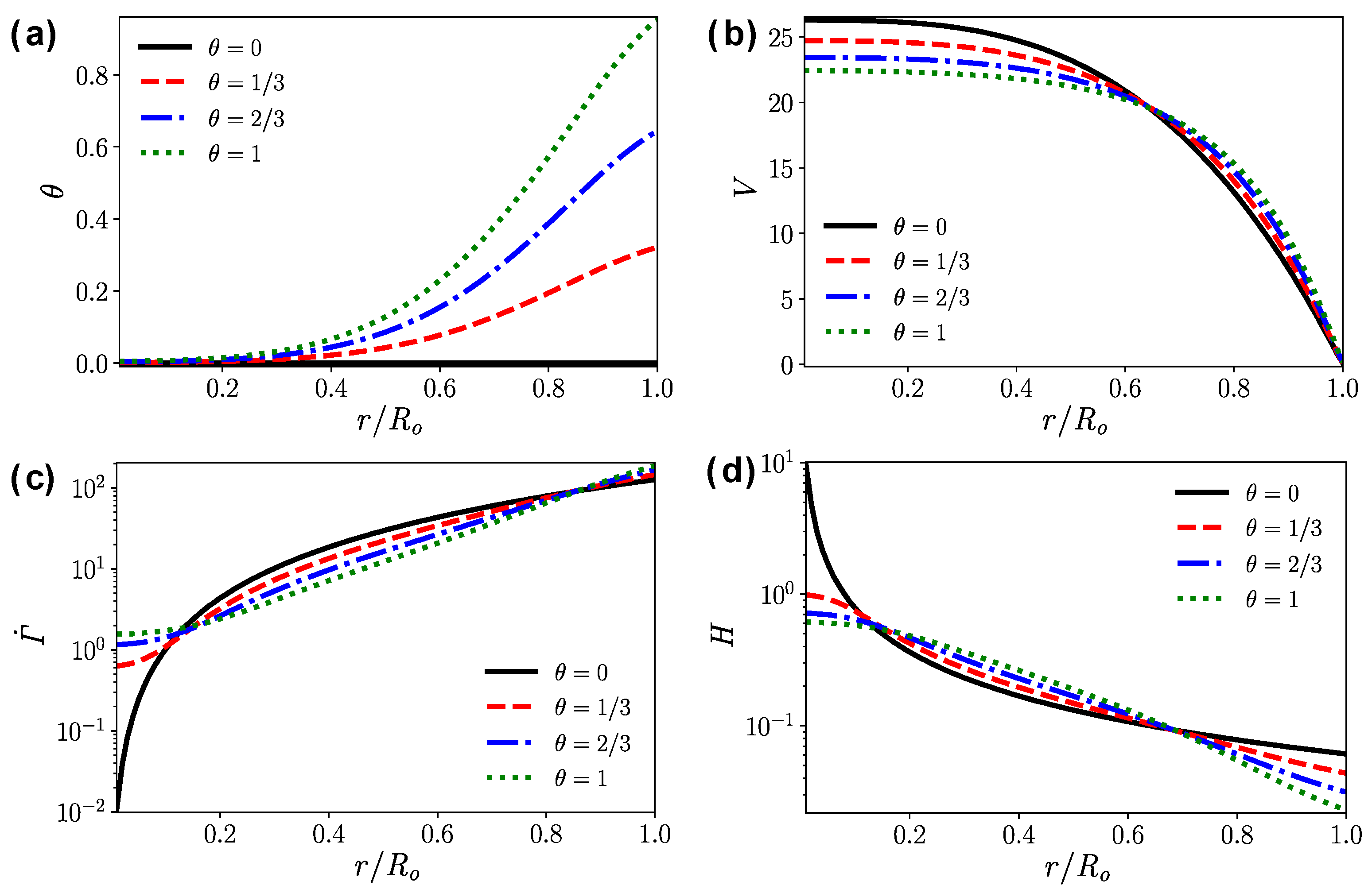
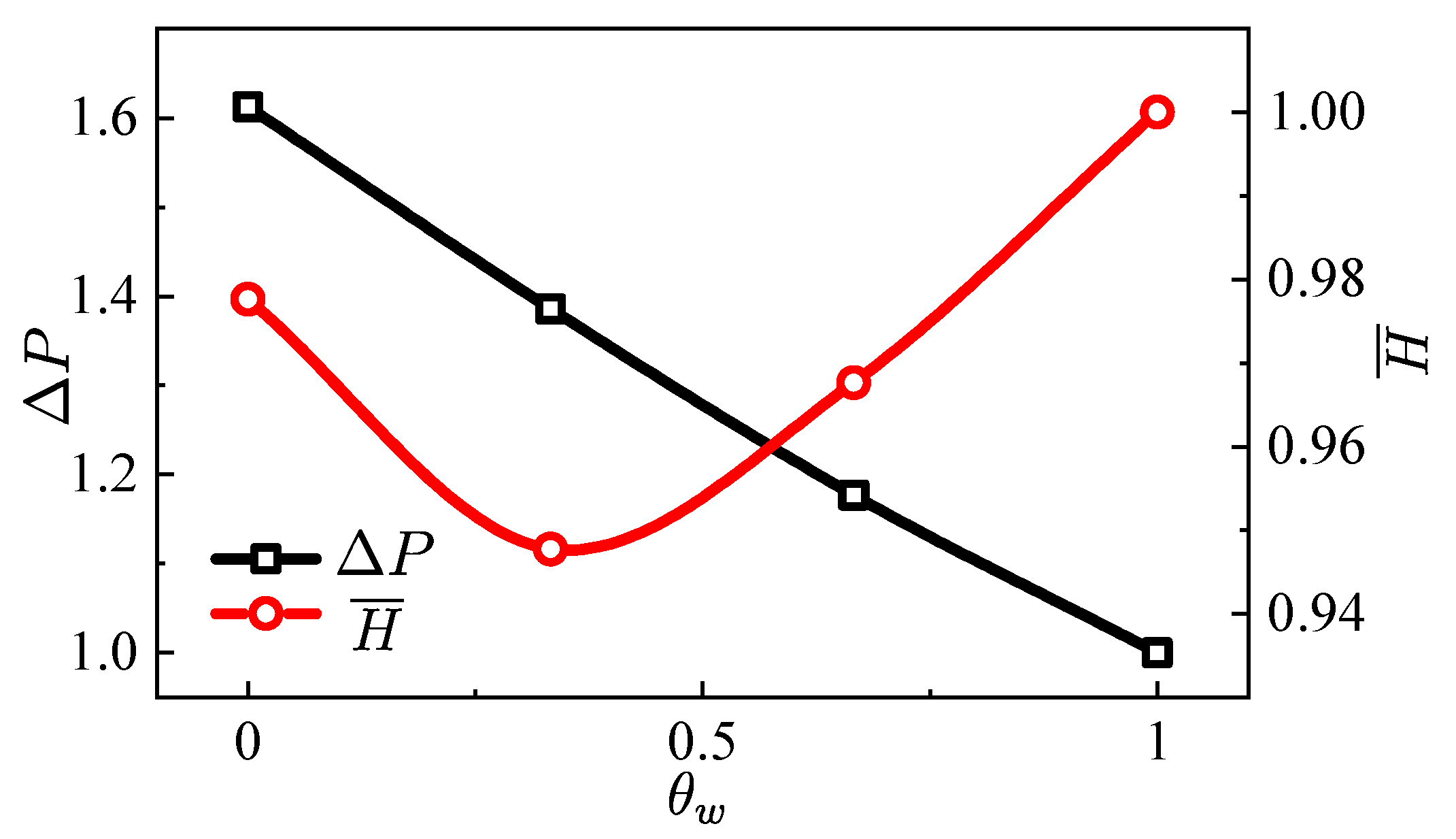
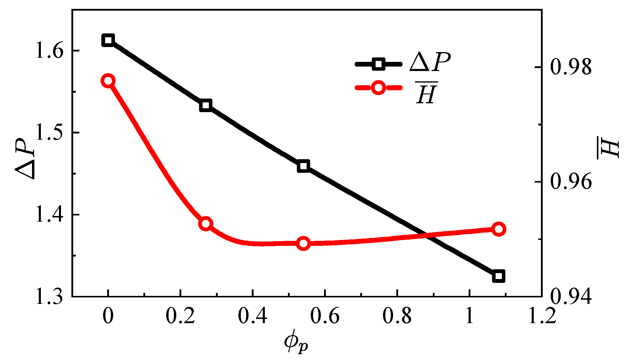
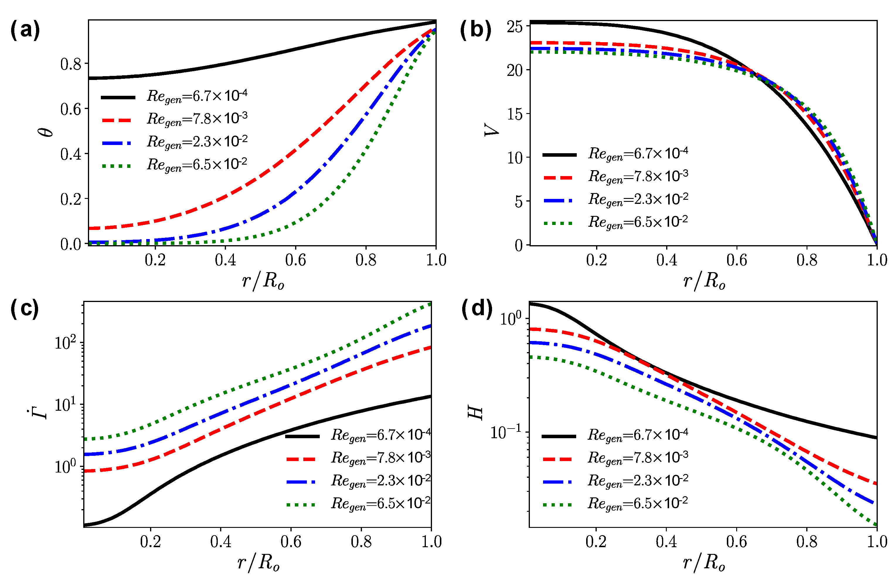
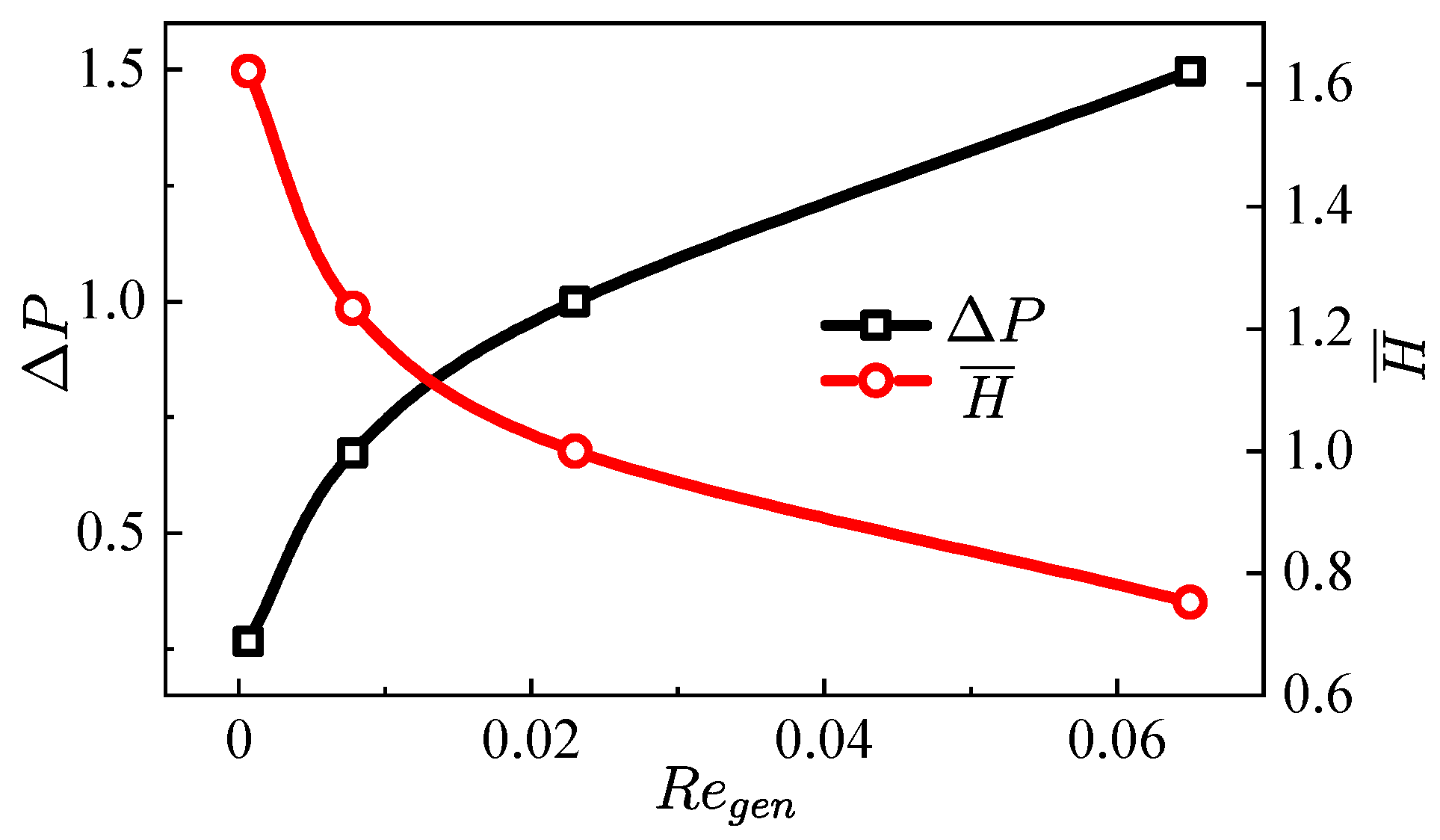
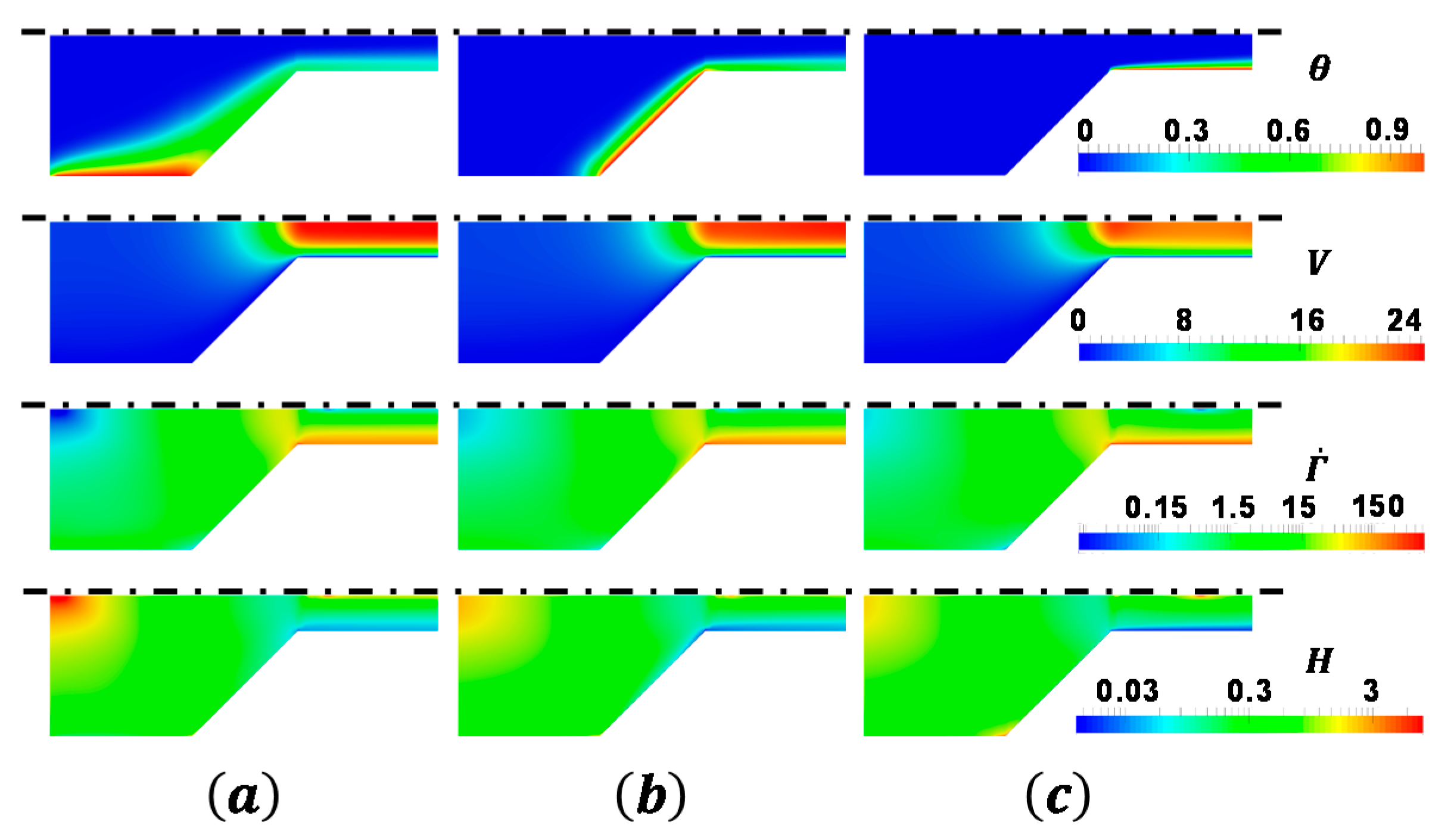
In the tapered injector, the gel is not fully heated before flowing out of the injector. The temperature gradient has a significant effect on the flow field. The larger the temperature gradient is, the blunter the velocity profile is.
(c)
Higher wall temperature significantly reduces the near-wall apparent viscosity, but it has the opposite effect on the apparent viscosity far away from the hot wall. In terms of the mean outlet apparent viscosity, the influence of temperature on the viscosity reduction is less than 5%.
(d)
Wall heating can greatly reduce the pressure drop in the transport system. In the range of the wall temperatures studied here, the pressure drop of the heated injector was reduced up to 38% when compared with the unheated condition.

Author Contributions

Numerical simulations, Q.-L.C.; Develop the framework of the paper and derive the equations, M.M. and F.F.; Prepare the manuscript, Q.-L.C., M.M., W.-H.L., F.F. and W.-T.W. All authors have read and agreed to the published version of the manuscript.

Funding

This work is supported by Natural Science Foundation of China No. 11802135 and the Fundamental Research Funds for the Central Universities No. 30919011401 and No. 309181A8802.

Conflicts of Interest

The authors declare no conflict of interest.

Nomenclature

K consistency index ( Pa · s n )
n power-law exponent
v velocity vector ( m / s )
v 0 reference velocity ( m / s )
V dimensionless velocity
T stress tensor ( Pa )
t time ( s )
b body force vector ( N / kg )
L gradient of velocity ( s 1 )
q heat flux vector ( W / m 2 )
e internal energy density ( J / m 3 )
I identity tensor
p pressure ( Pa )
P dimensionless pressure
D symmetric part of the velocity gradient ( s 1 )
T temperature ( K )
T 1 , T 0 reference temperatures ( K )
L dimensionless length of straight pipe
a temperature index ( 1 / K )
C p heat capacity ( J / ( K · kg ) )
k thermal conductivity ( W / ( m · K ) )
L r reference length scale ( m )
R dimensionless radius of straight pipe
R i dimensionless radius of the inlet of injector
R o dimensionless radius of the outlet of injector
R e Reynolds number
R e g e n generalized Reynolds number
D s dimensionless number related to the viscous dissipation
L e Lewis number
X , Y dimensionless position vector
r position vector ( m )
Greek symbols
ρ density ( kg / m 3 )
γ ˙ shear rate ( s 1 )
η dynamic viscosity ( Pa · s )
η r reference viscosity ( Pa · s )
η ¯ mean apparent viscosity ( Pa · s )
θ dimensionless temperature
θ i n dimensionless inlet temperature
θ w dimensionless wall temperature
α convergence angle of injector ( ° )
τ dimensionless time
Η dimensionless apparent viscosity
Η ¯ dimensionless mean apparent viscosity
ϕ p dimensionless heat flux
Γ ˙ dimensionless shear rate

References

  1. Ciezki, H.K.; Negri, M.; Weiser, V.; Naumann, K.W.; Program, P.T.; Program, T.; Grund, L.; Heterogenious, H.; Group, S.; Grund, L.; et al. Overview of the German Gel Propulsion Technology. In Proceedings of the 50th AIAA/ASME/SAE/ASEE Joint Propulsion Conference, Cleveland, OH, USA, 28–30 July 2014; pp. 1–16. [Google Scholar]
  2. Cao, Q.; Liao, W.; Wu, W.-T.; Feng, F. Combustion characteristics of inorganic kerosene gel droplet with fumed silica as gellant. Exp. Therm. Fluid Sci. 2019, 103, 377–384. [Google Scholar] [CrossRef]
  3. Natan, B.; Rahimi, S. The status of gel propellants in year 2000. Int. J. Energetic Mater. Chem. Propuls. 2009, 5, 172–194. [Google Scholar] [CrossRef]
  4. Arnold, R.; Anderson, W. Droplet burning of JP-8/Silica gels. In Proceedings of the 48th AIAA Aerospace Sciences Meeting Including the New Horizons Forum and Aerospace Exposition, Orlando, FL, USA, 4–7 January 2010; pp. 1–12. [Google Scholar]
  5. Yang, L.J.; Fu, Q.F.; Qu, Y.Y.; Zhang, W.; Du, M.L.; Xu, B.R. Spray characteristics of gelled propellants in swirl injectors. Fuel 2012, 97, 253–261. [Google Scholar] [CrossRef]
  6. Nahamoni, G.; Natan, B.; Nahamoni, G.; Natan, B. Investigation of the combustion process of gel propellants. In Proceedings of the 33rd Joint Propulsion Conference and Exhibit, Seattle, WA, USA, 6–9 July 1997; p. 2973. [Google Scholar]
  7. Ciezki, H.K.; Naumann, K.W.; Weiser, V. Status of Gel Propulsion in the Year 2010 with a Special View on the German Activities. In Proceedings of the Dtsch. Luft-Und Raumfahrtkongress 2010, Hamburg, Germany, 31 August–2 September 2010. [Google Scholar]
  8. Gafni, G.; Kuznetsov, A.; Har-Lev, D.; Natan, B. Experimental Investigation of a Ramjet Combustor Using an Aluminized Gel Fuel. In Proceedings of the 49th AIAA/ASME/SAE/ASEE Joint Propulsion Conference, San Jose, CA, USA, 14–17 July 2013; p. 3748. [Google Scholar]
  9. Matsibeker, E.; Natan, B. Numerical Solution of the Flowfield in an Aluminized Gel Fuel Ramjet. In Proceedings of the 49th AIAA/ASME/SAE/ASEE Joint PropulsionConference, San Jose, CA, USA, 14–17 July 2013; p. 3976. [Google Scholar]
  10. Natan, B.; Haddad, A.; Arieli, R. Performance assessments of a boron containing gel fuel ramjet. In Proceedings of the 47th AIAA Aerospace Sciences Meeting Including The New Horizons Forum and Aerospace Exposition, Orlando, FL, USA, 5–8 January 2009; p. 1421. [Google Scholar]
  11. Doi, M. Explanation for the 3.4-power law for viscosity of polymeric liquids on the basis of the tube model. J. Polym. Sci. Polym. Phys. Ed. 1983, 21, 667–684. [Google Scholar] [CrossRef]
  12. Doi, M. Explanation for the 3.4 power law of viscosity of polymeric liquids on the basis of the tube model. J. Polym. Sci. Polym. Lett. Ed. 1981, 19, 265–273. [Google Scholar] [CrossRef]
  13. Krieger, I.M. Rheology of monodisperse latices. Adv. Colloid Interface Sci. 1972, 3, 111–136. [Google Scholar] [CrossRef]
  14. Rahimi, S.; Natan, B. Numerical solution of the flow of power-law gel propellants in converging injectors. Propellants Explos. Pyrotech. 2000, 25, 203–212. [Google Scholar] [CrossRef]
  15. Rahimi, S.; Natant, B. The Injection Process of Gel fuels. In Proceedings of the 33rd Joint Propulsion Conference and Exhibit, Seattle, WA, USA, 6–9 July 1997. [Google Scholar]
  16. Rahimi, S.; Natan, B. Flow of gel fuels in tapered injectors. J. Propuls. Power 2000, 16, 458–464. [Google Scholar] [CrossRef]
  17. Bo, Z.; Mengzheng, Z. Numerical simulation of tube flow characteristics for gel simulation. J. Rocket Propuls. 2008, 34, 27–34. [Google Scholar]
  18. Yoon, C.; Heister, S.D.; Xia, G.; Merkle, C.L. Numerical modeling of injection of shear-thinning gel propellants through plain-orifice atomizer. J. Propuls. Power 2011, 27, 944–954. [Google Scholar] [CrossRef]
  19. Cao, Q.-L.; Massoudi, M.; Liao, W.-H.; Feng, F.; Wu, W.-T. Flow Characteristics of Water-HPC Gel in Converging Tubes and Tapered Injectors. Energies 2019, 12, 1643. [Google Scholar] [CrossRef] [Green Version]
  20. Shin, S.; Cho, Y.I. Laminar heat transfer in a rectangular duct with a non-Newtonian fluid with temperature-dependent viscosity. Int. J. Heat Mass Transf. 1994, 37, 19–30. [Google Scholar] [CrossRef]
  21. Varghese, T.L.; Gaindhar, S.C.; David, J.; Jose, J.; Muthiah, R.; Rao, S.S.; Ninan, K.N.; Krishnamurthy, V.N. Developmental studies on metallised UDMH and kerosene gels. Def. Sci. J. 1995, 45, 25–30. [Google Scholar] [CrossRef] [Green Version]
  22. Rahimi, S.; Peretz, A.; Natan, B. Rheological matching of gel propellants. J. Propuls. Power 2010, 26, 376–379. [Google Scholar] [CrossRef]
  23. Rahimi, S.; Natan, B. Atomization characteristics of gel fuels. In Proceedings of the 34th AIAA/ASME/SAE/ASEE Joint Propulsion Conference and Exhibit, Cleveland, OH, USA, 13–15 July 1998; p. 3830. [Google Scholar]
  24. Ellahi, R. The effects of MHD and temperature dependent viscosity on the flow of non-Newtonian nanofluid in a pipe: Analytical solutions. Appl. Math. Model. 2013, 37, 1451–1467. [Google Scholar] [CrossRef]
  25. Fu, Q.; Duan, R.; Cui, K.; Yang, L. Spray of gelled propellants from an impinging-jet injector under different temperatures. Aerosp. Sci. Technol. 2014, 39, 552–558. [Google Scholar] [CrossRef]
  26. Jyoti, B.V.S.; Baek, S.W. Rheological characterization of ethanolamine gel propellants. J. Energetic Mater. 2016, 34, 260–278. [Google Scholar] [CrossRef]
  27. Slattery, J.C. Advanced Transport Phenomena; Cambridge University Press: Cambridge, UK, 1999. [Google Scholar]
  28. Buongiorno, J. Convective Transport in Nanofluids. J. Heat Transfer 2006, 128, 240. [Google Scholar] [CrossRef]
  29. Wu, W.T.; Aubry, N.; Massoudi, M. Flow of granular materials modeled as a non-linear fluid. Mech. Res. Commun. 2013, 52, 62–68. [Google Scholar] [CrossRef]
  30. Roscoe, R. Suspensions, Flow Properties of Disperse Systems; Flow Properties of Disperse Systems; North. Holl. Publisher Company: Amsterdam, The Netherlands, 1953. [Google Scholar]
  31. Schowalter, W.R. Mechanics of Non-Newtonian Fluid; Pergamon Press: New York, NY, USA, 1978. [Google Scholar]
  32. Macosko, C.W.; Larson, R.G. Rheology: Principles, Measurements, and Applications, 1st ed.; Wiley-VCH: Weinheim, Germany, 1994. [Google Scholar]
  33. Carreau, P.J.; De Kee, D.C.R.; Chhabra, R.P. Rheology of Polymeric Systems: Principles and Applications Hanser; Hanser Publications: Cincinnati, OH, USA, 1997. [Google Scholar]
  34. Arnold, R.; Anderson, W.; Santos, P.H.S.; deRidder, M.; Campanella, O.H. Comparison of Monomethylhydrazine/hydroxypropylcellulose and Hydrocarbon/silica Gels. In Proceedings of the 48th AIAA Aerospace Sciences Meeting Including the New Horizons Forum and Aerospace Exposition, Orlando, FL, USA, 4–7 January 2010; p. 422. [Google Scholar]
  35. Macosko, C.W.; Krieger, I.M. Rheology: Principles, Measurements, and Applications. J. Colloid Interface Sci. 1996, 178, 382. [Google Scholar]
  36. Massoudi, M.; Christie, I. Effects of variable viscosity and viscous dissipation on the flow of a third grade fluid in a pipe. Int. J. Non-Linear Mech. 1995, 30, 687–699. [Google Scholar] [CrossRef]
  37. Winterton, R.H.S. Early study of heat transfer: Newton and Fourier. Heat Transf. Eng. 2001, 22, 3–11. [Google Scholar] [CrossRef]
  38. Massoudi, M. On the heat flux vector for flowing granular materials—Part I: Effective thermal conductivity and background. Math. Methods Appl. Sci. 2006, 29, 1585–1598. [Google Scholar] [CrossRef]
  39. Massoudi, M. On the heat flux vector for flowing granular materials—Part II: Derivation and special cases. Math. Methods Appl. Sci. 2006, 29, 1599–1613. [Google Scholar] [CrossRef]
  40. Zhang, M.; Che, Z.; Chen, J.; Zhao, H.; Yang, L.; Zhong, Z.; Lu, J. Experimental Determination of Thermal Conductivity of Water−Agar Gel at Different Concentrations and Temperatures. J. Chem. Eng. Data 2010, 56, 859–864. [Google Scholar] [CrossRef]
  41. OpenCFD. OpenFOAM Programmer’s Guide Version 2.1.0; OpenCFD, Ed.; Free Software Foundation, Inc.: Boston, MA, USA, 2011. [Google Scholar]
  42. Metzner, A.B.; Reed, J.C. Flow of non-newtonian fluids—Correlation of the laminar, transition, and turbulent-flow regions. Aiche J. 1955, 1, 434–440. [Google Scholar] [CrossRef]
  43. Dodge, D.W.; Metzner, A.B. Turbulent flow of non-Newtonian systems. Aiche J. 1959, 5, 189–204. [Google Scholar] [CrossRef]
  44. Rahimi, S.; Peretz, A.; Natan, B. On Shear Rheology of Gel Propellants. Propellants Explos. Pyrotech. Int. J. Deal. Sci. Technol. Asp. Energetic Mater. 2010, 32, 165–174. [Google Scholar] [CrossRef]
  45. Greenshields, C.J. OpenFOAM User Guide Version 7.0; OpenFOAM Found. Ltd.: London, UK, 2019. [Google Scholar]
  46. Li, X.F.; Tang, G.H.; Gao, T.Y.; Tao, W.Q. Simulation of Newtonian and non-Newtonian axisymmetric flow with an axisymmetric lattice Boltzmann model. Int. J. Mod. Phys. 2010, 21, 1237–1254. [Google Scholar] [CrossRef]
Figure 1. Experimental measurements and the model prediction of the viscosity of the water-gel. The experimental data is from [44]. The fitted parameters of Equation (8) are   K = 167.7978   Pa · s n ,   n = 0.4751 , a = 1.116 × 10 2   1 / K .
Energies 13 00821 g001
Figure 2. Geometries of (a) the straight pipe and (b) the tapered injector. R i and R o are the radii of the inlet and the outlet cross-sections, respectively. The red color indicates heated walls.
Energies 13 00821 g002
Figure 3. Contours of (a) velocity, (b) shear rate and (c) apparent viscosity in the straight pipe. The upper boundary is the axis of symmetry and the lower boundary is the wall with no-slip condition. The wall temperature is θ w = 1 and the inlet R e g e n is 0.1.
Energies 13 00821 g003
Figure 4. Dimensionless fully developed (a) velocity, (b) shear and (c) apparent viscosity profiles along Table 1 at the inlet are used as the reference parameters.
Energies 13 00821 g004
Figure 5. Dimensionless cross-section mean apparent viscosity ( Η ¯ ) at different temperature.
Energies 13 00821 g005
Figure 6. Contours of dimensionless temperature, velocity, shear rate and apparent viscosity of (a) non-heating walls and (b) heated walls. The dimensionless temperature of the inlet and the hot wall are 0 and 1, respectively. R e g e n = 2.3 × 10 2 .
Energies 13 00821 g006
Figure 7. Dimensionless (a) temperature, (b) velocity, (c) shear rate and (d) apparent viscosity profiles in the radial direction at the outlet for different wall temperatures. The inlet mean velocity, mean shear rate and mean apparent viscosity with θ w = 1 and R e g e n = 2.3 × 10 2 are used as reference parameters.
Energies 13 00821 g007
Figure 8. The dimensionless pressure drop ( Δ P ) and cross-section mean apparent viscosity ( Η ¯ ) at different temperatures. The pressure drop and the mean outlet apparent viscosity when θ w = 1 and R e g e n = 2.3 × 10 2 are used as reference parameters.
Energies 13 00821 g008
Figure 9. Contours of dimensionless (a) temperature, (b) velocity, (c) shear rate and (d) apparent viscosity for a constant dimensionless wall heat flux ϕ p = 1.08 . The reference heat flux is calculated using reference temperature ( T 0 and T 1 ), inlet radius ( R i ), and the thermal conductivity of the gel. The dimensionless inlet temperature is 0 and R e g e n = 2.3 × 10 2 .
Energies 13 00821 g009
Figure 10. The dimensionless pressure drop ( Δ P ) and the cross-sectional mean apparent viscosity ( Η ¯ ) for different values of the wall heat flux. The pressure drop and the outlet mean apparent viscosity when θ w = 1 and R e g e n = 2.3 × 10 2 are used as the reference parameters.
Energies 13 00821 g010
Figure 11. The dimensionless (a) temperature, (b) velocity, (c) shear rate and (d) apparent viscosity profiles in the radial direction for various R e g e n . The inlet mean velocity is used as the reference velocity. The mean shear rate and the mean apparent viscosity when θ w = 1 and R e g e n = 2.3 × 10 2 are used as reference values.
Energies 13 00821 g011
Figure 12. The dimensionless pressure drop ( Δ P ) and the mean cross-sectional apparent viscosity ( Η ¯ ) for various R e g e n . The pressure drop and the mean outlet apparent viscosity when θ w = 1 and R e g e n = 2.3 × 10 2 are used as reference parameters.
Energies 13 00821 g012
Figure 13. Contours of the dimensionless temperature, velocity, shear rate and apparent viscosity when the walls of (a) the upstream isometric section, (b) the convergent section and (c) the downstream section are heated with a constant temperature. The dimensionless temperature at the inlet and the hot wall are 0 and 1, respectively. R e g e n = 2.3 × 10 2 .
Energies 13 00821 g013
Figure 14. The dimensionless (a) temperature, (b) velocity, (c) shear rate and (d) apparent viscosity profiles in the radial direction for different heating positions. The inlet mean velocity, mean shear rate and mean apparent viscosity when θ w = 1 and R e g e n = 2.3 × 10 2 are used as reference parameters.
Energies 13 00821 g014
Table 1. Boundary conditions for the numerical simulations.
Boundary TypeStraight Pipe
PressureVelocityTemperature
WallZero gradientFixed value (0)Fixed value
InletCyclicCyclicCyclic
OutletCyclicCyclicCyclic
Boundary typeTapered injector
PressureVelocityTemperature
WallZero gradientFixed value (0)Fixed value/gradient
InletZero gradientFixed valueFixed value
OutletFixed value (0)Zero gradientZero gradient
Table 2. Mesh dependency study of the tapered injector.
Grid NumberMean Apparent Viscosity (Pa·s)
Grid A17501.026
Grid B70001.049
Grid C28,0001.059
Table 3. Effects of heating conditions on the pressure drop and the outlet mean apparent viscosity.
Non-heatedCase aCase bCase cAll-heated
Δ P 1.6131.2961.2261.2191.000
Η ¯ 0.9780.9500.9731.0351.000

