Article

Open Circuit Performance of Axial Air Gap Flux Switching Permanent Magnet Synchronous Machine for Wind Energy Conversion: Modeling and Experimental Study

Groupe de Recherche en Électrotechnique et Automatique du Havre (GREAH), Université Le Havre Normandie, 76600 Le Havre, France
*
Author to whom correspondence should be addressed.
Energies 2020, 13(4), 912; https://doi.org/10.3390/en13040912
Submission received: 30 December 2019 / Revised: 9 February 2020 / Accepted: 12 February 2020 / Published: 18 February 2020
(This article belongs to the Special Issue Design, Control, and Optimization of Flux Switching Machine)

Abstract

:
The aim of this paper is to present the design and modeling of a machine that possesses some advantageous characteristics for wind energy conversion applications. The studied machine is a double stator inner rotor axial airgap flux switching permanent magnet machine (AFSPM). The paper will start by presenting this type of machine and its points of interest. Then, it will continue by introducing the constructed prototype and its specifications and structure. This prototype has been designed based on a reference specification used at GREAH to develop different prototypes and compare their performances. The second part will introduce the reluctance network model specifically constructed for this type of machine. The constructed model was validated by comparing its results to the results from the finite element method model. Finally, the experimental results will be presented and compared to the reluctance network (RN) model results where satisfying agreement between both results was obtained.

1. Introduction

In recent years, wind energy has proved itself to be an effective and promising renewable energy source. Today, electricity-generating wind turbines employ proven and tested technology and provide a clean and sustainable energy supply. However, this technology still has a lot of challenges to overcome and constraints to respect. Hence, research on the most vital part of this energy system, the electric generator, has focused on finding and testing new machine designs that can help overcome the challenges at hand while respecting the constraints. Flux switching machines have proven to be a very interesting machine type for wind energy applications [1]. These machines possess the merits of switched reluctance and the classical rotor PM synchronous machines. Their high torque density, high efficiency, strong robustness, and convenience of cooling [2,3,4,5] make them very good candidates for wind energy applications.
Also, axial flux machines (axial airgap) have proven to have several advantages over their radial counterparts [6]. It is said that the axial flux permanent magnet machines are one of the best choices for the direct-drive wind power system because of their shorter axial length, small size, high power density, and so forth [7,8,9]. Hence, combining the merits of the axial field and the flux switching machines, an axial airgap flux switching permanent magnet synchronous machine suitable for small wind energy turbines (order of 10kW) was designed and prototyped. The design is based on specifications that the GREAH laboratory has been working on for a long time [10,11,12,13]. These specifications are used as a reference to design different types of alternators and then compare their performance. In [11,12], the focus was on the design, development, and analysis of a surface-mounted permanent magnet (PM) axial field prototype, while in [10,13], the focus was on a flux switching PM axial field machine.
The first part of the paper will focus on presenting the AFSPM and its prototype that was designed and modeled at GREAH. The second part will be about the magnetic modeling of this machine. A reluctance network model for this machine will be presented, and it will be validated by comparing its results to the results generated by the finite element method model. Finally, experimental results collected from the prototype will be presented and compared to the results of the magnetic model presented previously. The paper will end with a discussion and conclusion.

2. AFSPM for Wind Energy Conversion

2.1. Axial Flux vs. Radial Flux Machines

Radial flux machines are the most common machine types with the airgap flux direction perpendicular to the axis of rotation. Axial flux machines, on the other hand, still not as common as the radial flux ones, have an airgap flux parallel to the axis of rotation. Compared with the traditional radial field PM machine, the axial field PM machine has more advantages, such as shorter axial length, better heat dissipation, and higher efficiency [14]. In [6], an in-depth comparison between the radial and axial flux PM brushless machines was conducted. For different output power levels, one radial flux and four axial flux topologies were compared. It was concluded that the axial field machines have a smaller volume for a given power rating, making its power density very high. For a given magnet material and air gap flux density, the rotor moment of inertia of the radial field machine was larger than all of the axial field machines in the comparison. The weight of iron required in the axial field designs is lower than that required in the radial field designs, making the active weight of axial field machines smaller. The slotless axial field machines require more magnet material than the radial field machines. However, the slotted axial field machines require less material than the radial field machines. The copper loss in the axial flux slotless dual airgap machines is higher than that of the slotted radial field machine. The machine under study in this paper is a slotted dual airgap axial flux machine, so based on the comparison above, it has several advantages compared to the radial flux structure.

2.2. Flux Switching Machines (FSMs)

FSMs are prime candidates for applications requiring high torque densities, high speeds, or heat dissipation-relieved constraints, as in embedded applications [15]. The principle of flux switching dates back to the 1950s when it was applied to a 6/4 single-phase machine presented in [16]. One of the first three-phase machines based on this idea was studied in the 1990s in France in the LESiR laboratory [17]. Since then, several research teams have examined this structure in order to study its properties (strong points, limitations) and to delimit their field of application. Nevertheless, this type of machine remains, until this moment, at the stage of laboratory prototypes.
In these machines, the active elements (permanent magnets and windings) are located at the stator [18]. The concentrated tooth type windings imply low stator Joule’s losses due to the short end windings and a good filling factor [19]. The magnets are placed with alternating polarity and operate in flux concentration, allowing the use of magnets with a lower magnetic remanence like ferrites. In addition, this configuration allows for easier cooling of the magnets using any refrigerant [20]. As a result, these machines combine the robustness of variable reluctance machines with the high-power density of permanent magnet synchronous machines [21]. However, compared to conventional machines with fractional permanent magnets with the same dimensions, FSM has finer stator teeth and a reduced slot area due to magnets placed between the cores. Unfortunately, this constraint leads to high local magnetic saturation and magnetic stresses and consequent vibrations [19]. In addition, the cogging torque in the FSM is relatively high compared to conventional machines with PMs placed in the rotor because of its doubly salient nature and the high flux density resulting from the effects of the flux concentration of the magnets placed between the stator blocks (one stator block contains two teeth and one slot).
The conventional PM machine has the risk of irreversible magnet demagnetization, which may be caused by the rotor temperature rise. Flux-switching PM can avoid the potential irreversible demagnetization problem because both the magnets and armature windings are located in the stator instead of the rotor [22]. The separation of the PMs (which are usually one of the expensive parts of the machine) from the moving structure (rotor) is very good and important, especially for direct-drive wind turbines where accidents can directly damage the machine’s rotor.

3. AFSPM Prototype Structure and Specifications

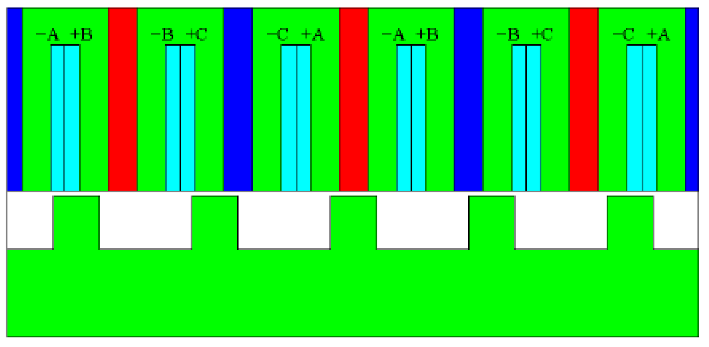
The AFSPM prototype to be studied is a 10 kW three-phase generator with a nominal speed of 375 rpm intended for direct drive small wind energy turbines. The configuration of this flux switching machine is a double-sided stator with an internal rotor. Each one of the two identical stators contains 12 modular U-shaped laminated blocks between which magnetized permanent magnets (PMs) are sandwiched circumferentially. In order to operate in flux concentration, the magnets’ polarities alternate from one magnet to another (PM1: S-N, PM2: N-S). The AFSPM winding is a two-layer dental juxtaposed winding where each slot is occupied by two phases (Figure 1). Each coil is composed of 30 turns with a fill factor of 0.6. The copper conductors are housed in the Ns stator slots so as to achieve a three-phase winding. The winding configuration chosen for the machine is ABC-ABC (Figure 2), and this configuration was chosen because it gives a sinusoidal electromotive force (EMF).
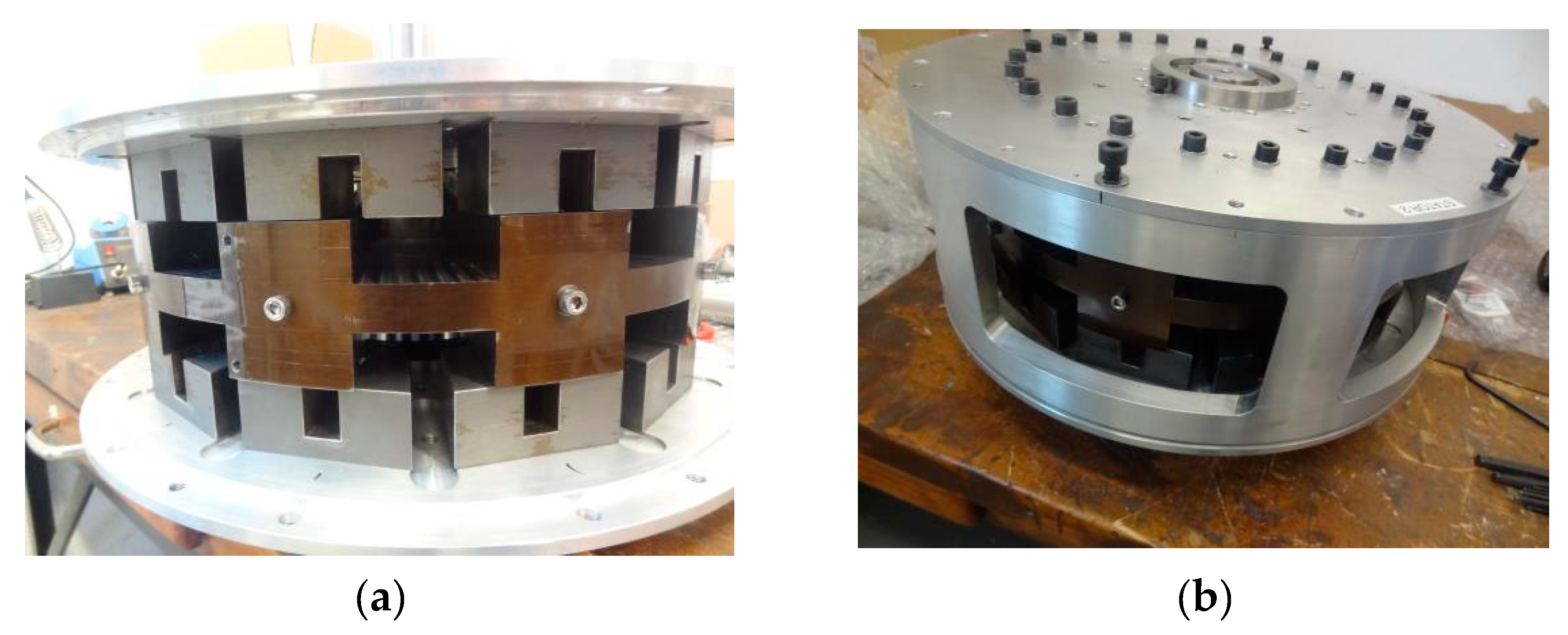
The mobile part of this machine, “the rotor”, is a completely passive part constituted of stacks of ferromagnetic sheets and comprises 10 teeth (Figure 3). The median plane of the rotor is a plane of symmetry, so it is enough to model half of the machine in the axial direction.
Moreover, the magnetic period of the machine is to be calculated using the following formula:
θ p e r =   θ t o t a l G C D ( N s , N r ) ,
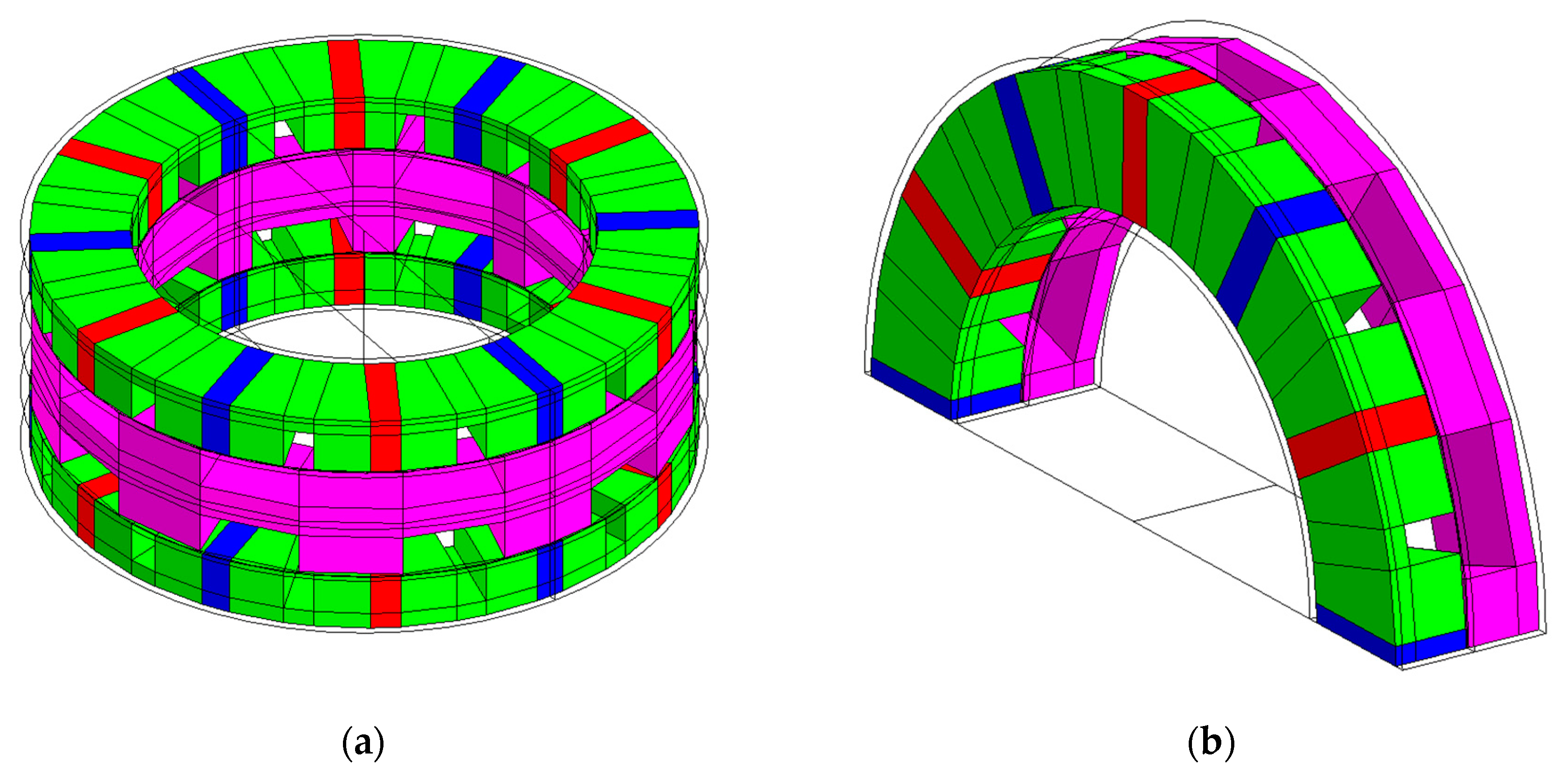
So, the magnetic period corresponds to half the machine total length (GCD (12, 10) = 2). Hence, the study will be done in one-quarter of the machine geometry (Figure 4). The complete geometry and dimensions of the machine are described in Table 1 below. The width values are expressed in (°) and represent the width at the mean radius of the machine. To clear any confusion regarding the width values, a rotor and stator plan schematic with dimensions is shown in Figure 5. Moreover, the dimensions’ nomenclature is illustrated in Figure 6, which shows the 2D plan that will be used for modeling in the next section.

3.1. Choice of Design Parameters

The design parameters of this machine were chosen based on several studies and a previously built prototype at GREAH [11,12], which was an axial field surface mounted permanent magnet synchronous machine (SMPMAF; Figure 7). Many parameters were chosen similar to the parameters of that prototype because having two similar-sized machines with different types is good for comparison, analysis, and assessment.
The choice of the external radius of the machine was fixed at 0.186 m due to the fact that the radius of the nacelle should not exceed 10%–15% of the radius of the wind turbine, and since for axial field machines the power output is proportional to the cube of their external diameter [10]. The choice of the structure of the studied AFSPM could be justified by [23,24,25,26]. These works focused on the analytical optimization of synchronous three-phase flux-switching machines in order to maximize the average electromagnetic torque and minimize the cogging torque. According to [27], the 12/10 configuration makes it possible to reduce the torque ripples responsible for vibrations and acoustic noise.
The choice of the width of the stator and rotor slots was based on the solution of an optimization problem to maximize the mean electromagnetic torque and minimize the cogging torque done in [19,25]. The quantities are computed for this model using a quasi 3D FEM model. Figure 8a,b from [28] show the effect of the rotor tooth width on the cogging torque and the electromagnetic torque, respectively, when the stator tooth width was fixed at 7.5°. It can be noted that the required width to minimize the cogging torque and maximize the electromagnetic torque was equal to 11.63°.

4. Reluctance Network Magnetic Model (RN)

The method of equivalent reluctance networks (RN) is based on Ohm’s law for magnetic circuits:
U μ i =   R μ i Φ i ,  
and magnetic law for nodes (equivalent to Kirchhoff’s laws),
i = 1 n Φ i =   0 ,  
and meshes
k = 1 m U μ k =   0 ,  
It is one of the oldest methods of modeling and studying magnetic circuits in electrical machines and transformers. As such circuits are becoming increasingly complicated, the equivalent networks have been developed into extensive multinode systems. The main benefits of using the RN are evident when calculating three-dimensional fields of complicated geometries, as significant savings in computing time and effort may be achieved owing to the efficiency of the formulation [29].
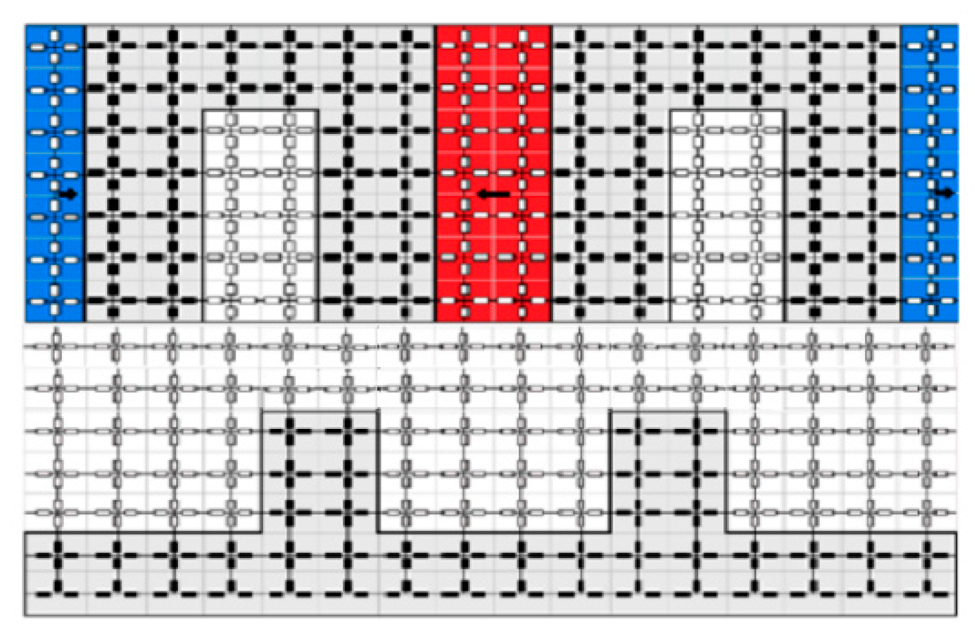
In practice, this approach subdivides the studied domain into elementary volumes or surfaces. Each volume or subdivision contains elementary elements with reluctances (i.e., 4 reluctances in 2D or 6 reluctances in 3D) implicitly representing the flux tubes of the modeled machine. Figure 9 shows an example of a meshed flux switching machine section.
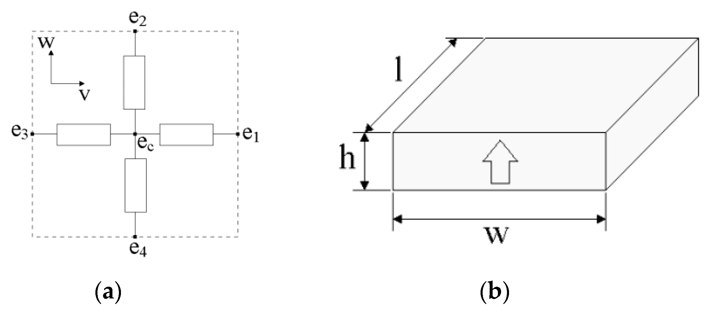
The flux in a block or in an elementary volume can traverse in different directions and not in one direction (the unidirectional case). Thus, each elementary block consists, in 2D, of four branches connected through a central node and the four lateral nodes. Each branch consists of one reluctance and possibly a magnetomotive force (MMF) source or a flux source (Figure 10a). In this case, the elementary flux tube is modeled by a fixed dimension block. Permanent magnets can either be modeled by a flux source in parallel with one permeance or a magnetomotive force (MMF) in series with one permeance [30].
Parameters characterizing the PM regions are expressed depending on the geometry and characteristics of the modeled PM. Our modeled PM region is a rectangular parallelepiped (Figure 10b), and it can be represented by
{ P p m = μ 0 μ r l w h Φ p m = B r l w
The full magnetic period should be modeled, which is equivalent to half the machine length as explained before. The model is a 2D model, so the 3D structure of the studied machine will be transformed into a linear 2D structure. Moreover, the nonlinearity of the materials will not be taken into account, so the generated system will be a linear system.
The reluctance elements to be used for this problem are the same as shown in Figure 10a. Every single element of this block has a predefined length and a height. The length and height of the elements may or may not be maintained constant across the whole domain. To simplify the model, suppositions were made before its construction: all the nodes of the very bottom line of the modeled domain have a zero magnetic scalar potential value, the permeability of the PM region is considered same as the air (equal 1), and air surrounding the machine is not taken into account. Meaning, it is considered that no flux is getting out of the stator top or bottom. All the dimensions in the x-direction (wdr, wer, wds, wes, wa, LTotal, Lperiod) in this model are calculated on the mean radius of the machine (Rmean).
{ R m e a n =   R e x t + R i n t 2 w = R θ
It was challenging to get uniform mesh across the horizontal direction (constant “length” value of the reluctance element) since the stator and rotor have different dimensions (different teeth and slots sizes). Having a non-uniform mesh across the horizontal direction means that it will be hard (but possible) to connect the moving rotor nodes to the stationary stator nodes. A workaround would be to consider the air gap as a sliding surface where both the stator and rotor nodes connect to this common surface and then use interpolation in order to specifically determine the values of U at a certain point of this surface, as in [31]. In order to avoid going into complications like this, a uniform mesh across the horizontal direction was constructed, resulting in a definite connection between the moving rotor nodes and fixed stator nodes. In order to get a uniform mesh, a very large number of nodes in the horizontal direction was considered.
Across the vertical direction, it is not important to keep a uniform mesh (constant “height” value of the reluctance element). Indeed, it is important to get a fine vertical mesh at the airgap region in order to get a relatively good precision for the cogging torque computation. The total height of the domain is   y = w d r + w a + e = 35 + 35 + e = 70 + e   m m where e is the air gap width.
The minimum displacement step of the rotor is the length between the two nodes. The movement of the rotor is simulated by manipulating the reluctance matrix after each rotor step
{ R k + 1 ( i , i + 1 ) =   R k ( i 1 , i ) R k + 1 ( i , i + m ) =   R k ( i 1 , i 1 + m ) R k + 1 ( i , i m ) =   R k ( i 1 , i 1 m )
where k is the step number and i is the node number (i = 1…, nn). Figure 11 below demonstrates the reluctance manipulation process where each color represents a reluctance value. When the rotor moves one step, the reluctance between nodes 721 and 361 (in red) becomes the reluctance between nodes 722 and 362, and so the reluctance values between the rotor nodes are exchanged in order to adapt for the new position of the rotor, and then this process is repeated on each rotor step. A flowchart for the software program is supplied in Figure A1 of Appendix A. The full program is available on a GitHub repository, and its link is available in the “supplementary materials” section.

4.1. Quantities Calculation

The linear system of equations to be solved on each rotor step is
[ P ] . [ U ] = [ Φ ] ,
where [ P ] (nn x nn) is the permeances matrix; [Φ] (nn x 1) is the source vector, elements of which are related to geometry distribution and physical properties of magnetic field sources (magnetic remanence and current density distributions); and [ U ] (nn x 1) is the vector of magnetic scalar potential on each node of the grid. Using the values in [ U ] (which are unique for each rotor step) we can get for each rotor step some useful local and global quantities such as the flux, the magnetic field, the EMF, the electromagnetic torque, and so forth.
The flux in the stator teeth, and hence the phases, can be determined using the resulting magnetomotive force values. The equation to determine the flux is simply
Φ =   Δ U . P ,
The flux at multiple branches will be determined and then added up to form the flux in a certain tooth. Adding the flux in teeth leads to the flux in phases. Then, the flux linkage value is determined by multiplying by the number of turns of a coil N (N = 30). Finally, the coils of one phase in a single stator are connected in series, and the phases’ terminals from the two stators are considered to be connected in series, so the flux linkage is multiplied by a coefficient to take into account the coils that were eliminated by periodicity and symmetry and to get the total flux in a certain phase   Φ t . The EMF generated on each phase was calculated using the simple approximate derivative formula
E M F =   Δ Φ t Δ t ,
The time values were calculated according to the machine’s nominal speed of 375 rpm. The magnetic induction can be also determined in both x and y directions using the equation
B =   ϕ S ,
where S is the surface whose normal is parallel to the direction of the magnetic induction vector to be determined. The electromagnetic torque (equal to the cogging torque in the case of open circuit performance) is calculated using Maxwell’s stress tensor [32]:
{ T =   l a c t R μ 0 l B n . B t . d l l a c t = R e x t R i n t ,
where Bn and Bt are the normal (y-direction) and tangential (x-direction) magnetic inductions in the airgap respectively, l is the contour surrounding the surface that we desire to calculate the torque on, lact is the machine’s active length, R is the radius at which the model is calculated (in our case it is the mean radius), and μ 0 is the air magnetic permeability since the calculation is done in the air gap region.

4.2. Finite Elements Method Model

The finite element method (FEM) is a numerical method like the finite difference method but is more general and can be powerful for the usage in applications and problems that have complex geometries, physics, and boundary conditions. In FEM, a given domain is subdivided into smaller subdomains, and over each subdomain, the equations that govern it, according to its physical and geometrical properties, are approximated and computed. Having a set of approximate equations that are basically simple polynomials can make dealing with the whole problem easier, and of course the set of regions should fit together in a sense that the functions and the derivatives are continuous at the connecting points [33].
For the AFSPM, a FEM model was created during the design stages using the FLUX commercial software. Both 2D and 3D models were created, but since the RN is a 2D model, its results will be compared only to the 2D FEM model. In Figure 12 below, the complete geometry and mesh of the 2D FEM model are shown. Figure 12a shows the geometry only (without meshing) where the colored surfaces represent different material properties (air, ferromagnetic material, etc.). For example, the area in red represents the exterior air surrounding the machine. Figure 12b shows the meshed geometry where the mesh is dense in areas where the flux changes are significant and important to study.

4.3. Results

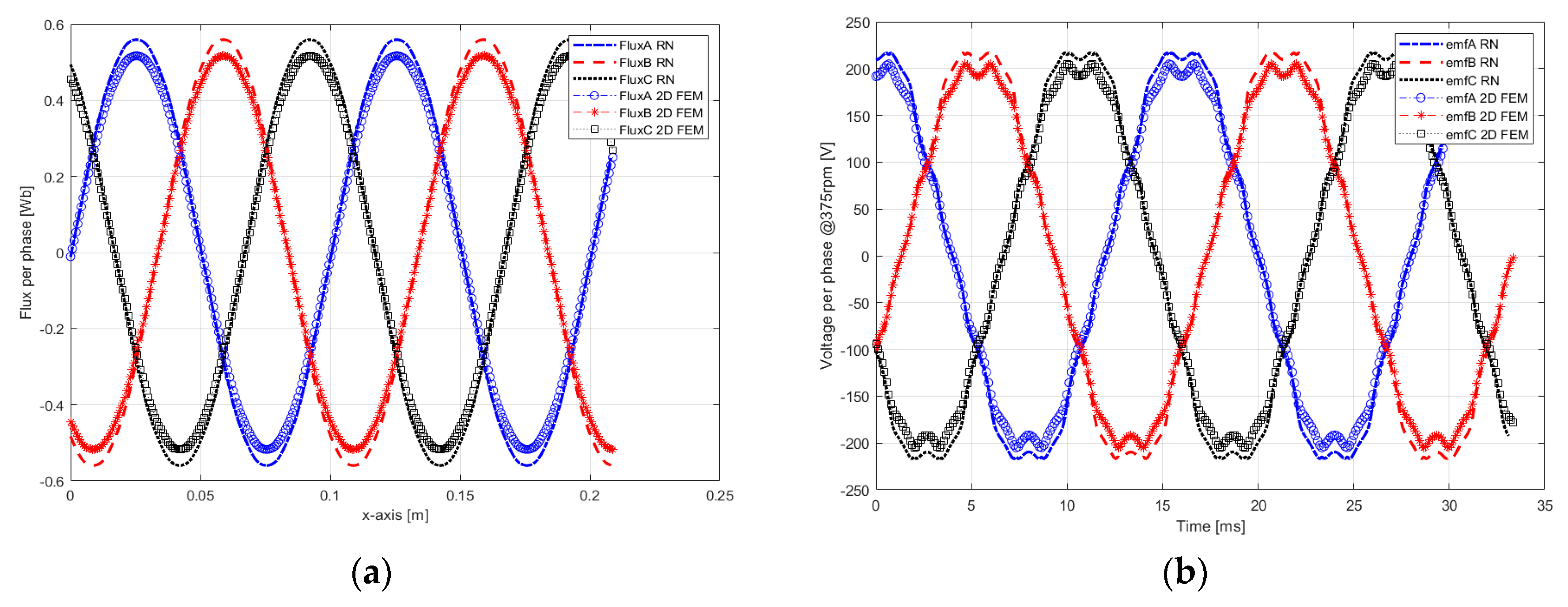
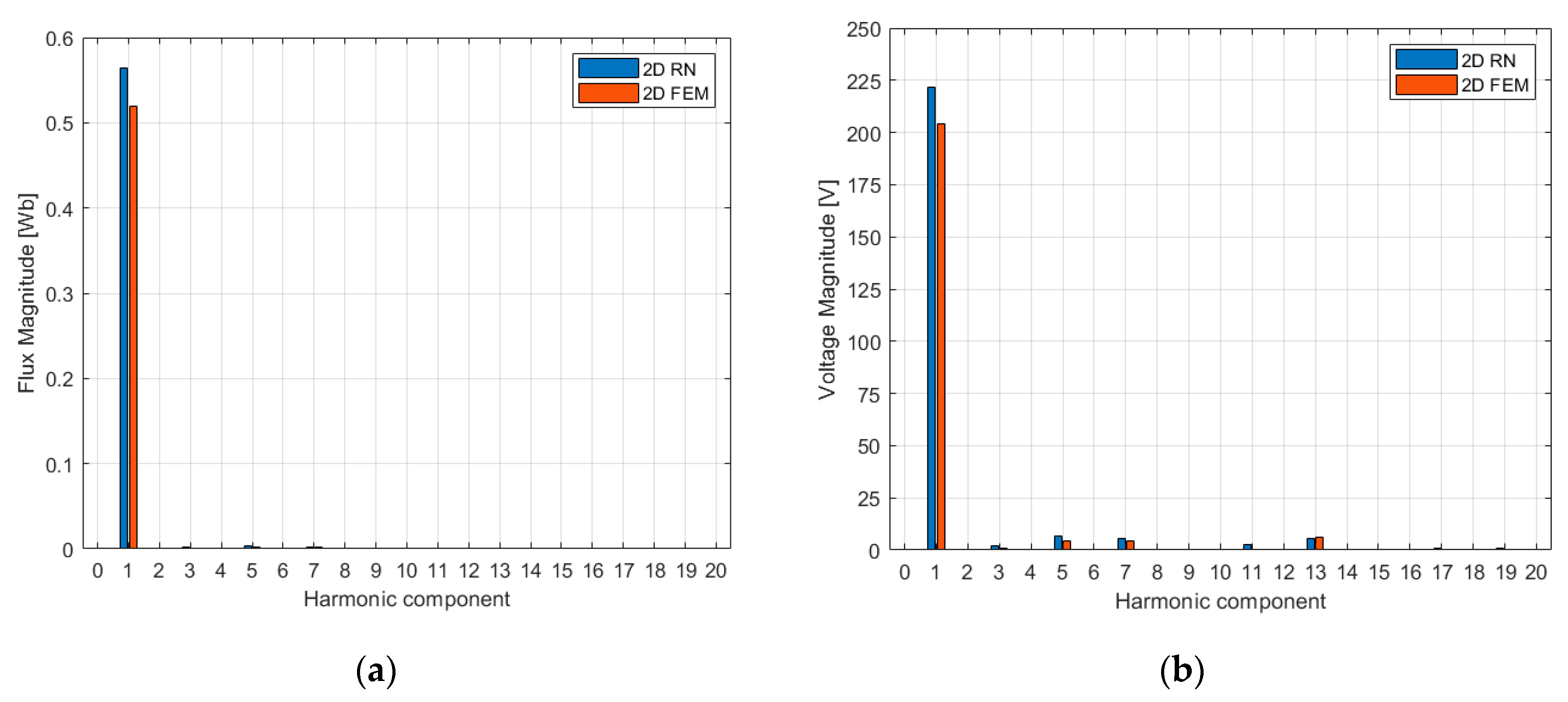
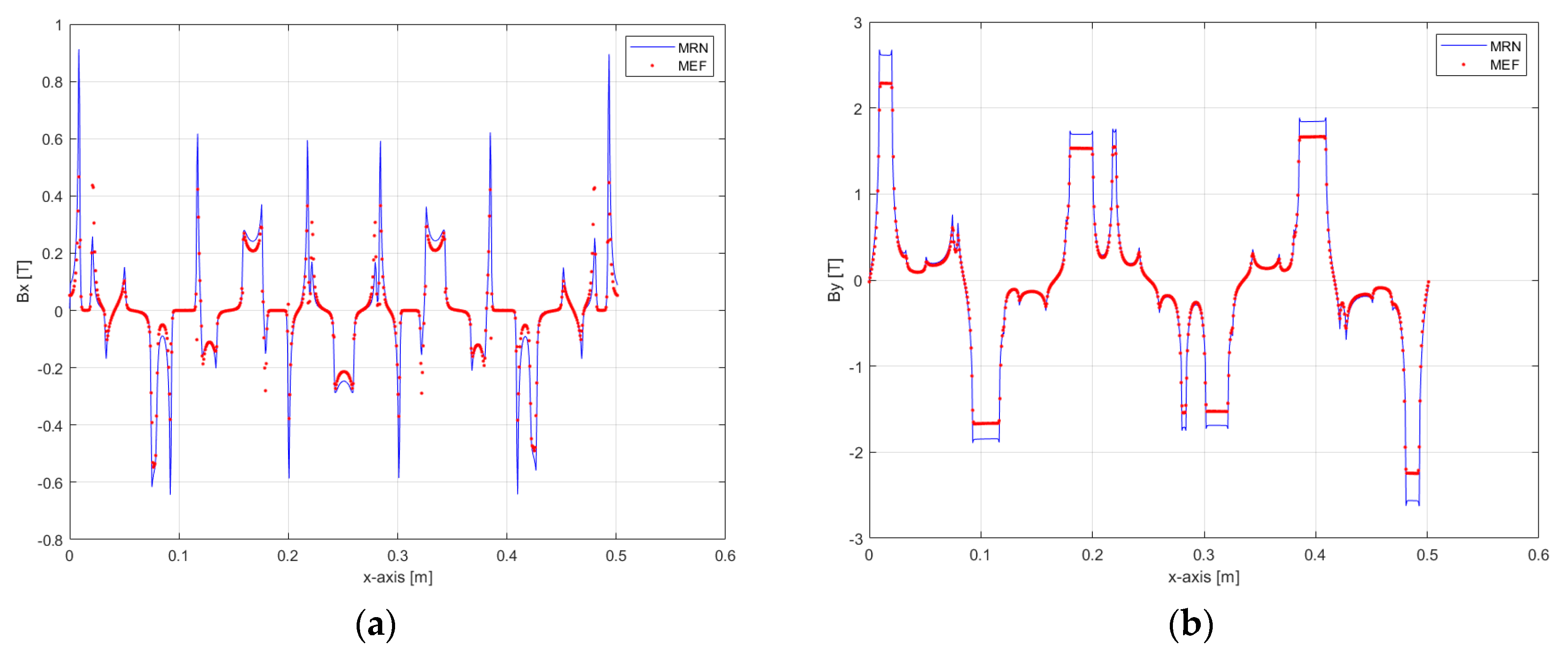
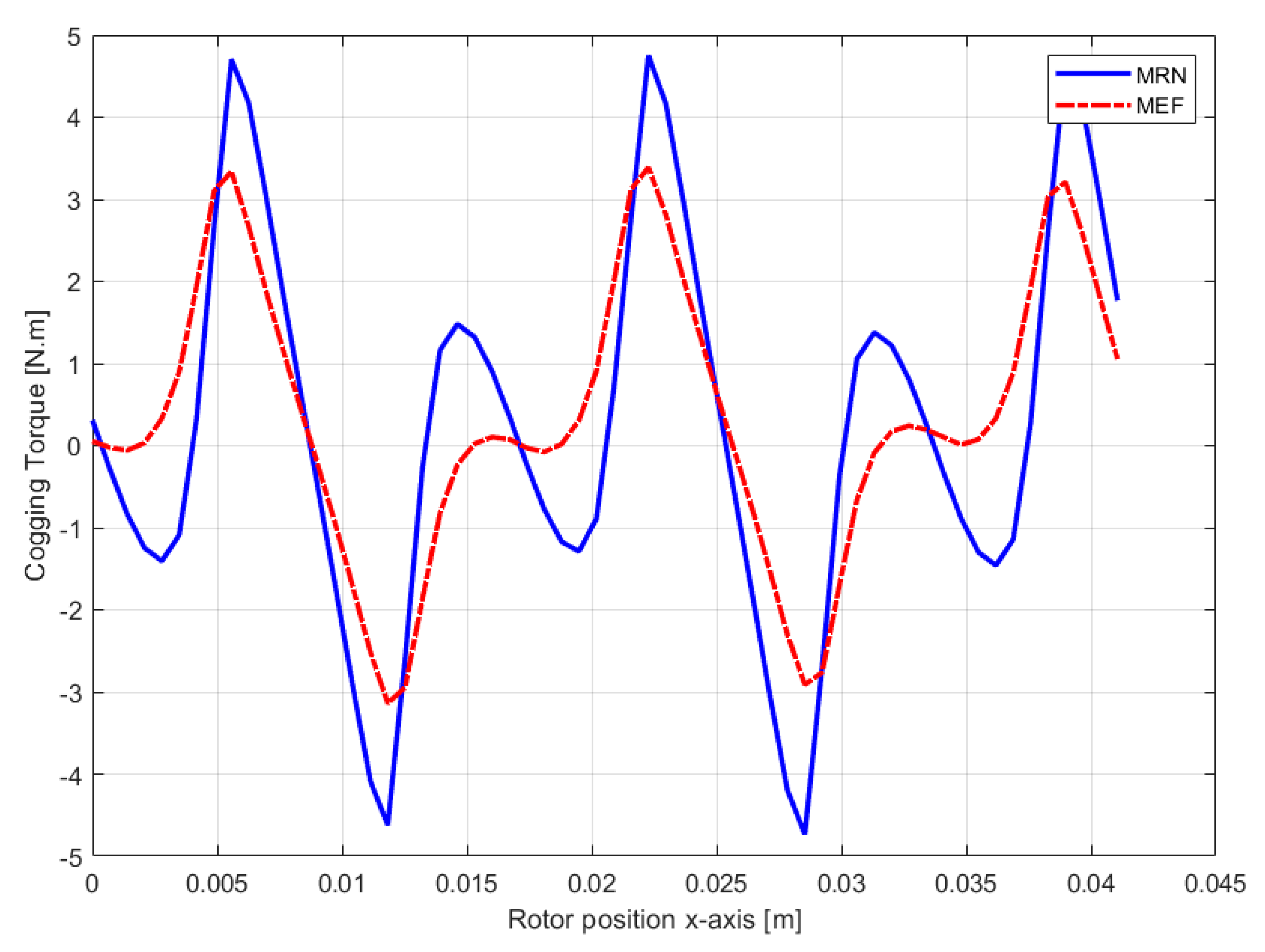
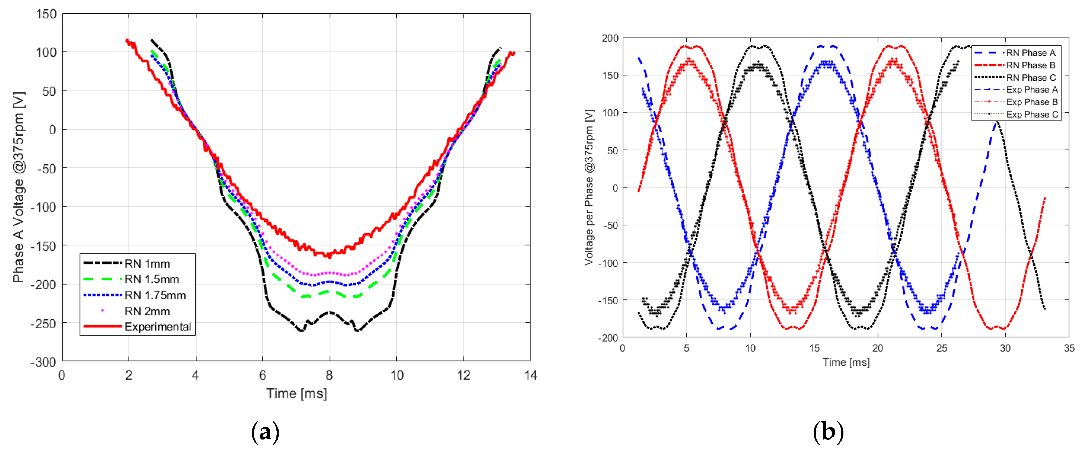
Different quantities were calculated and compared with results from a 2D finite element method model. All the calculated quantities are below in Figure 13a,b, Figure 14, Figure 15a,b, and Figure 16. By observing the results and comparing the values of the two models, the common observation for all the quantities generated by the RN model was that their peak values were slightly higher than those of the 2D FEM model. From the frequency spectrum analysis shown in Figure 14, it can be seen that the results from both models generated very good sinusoidal waves with almost zero harmonic components. The most affected quantity by the difference was the cogging torque. It is mainly because two magnetic induction terms are multiplied in its equation, so the difference will be multiplied as well. Nevertheless, the results were still satisfying, and we can say that this model is a valid 2D model for this machine. In the next section, it will be shown that with all the simplifications done to this model it still performed well when comparing its results to the experimental results.

5. Experimental Study

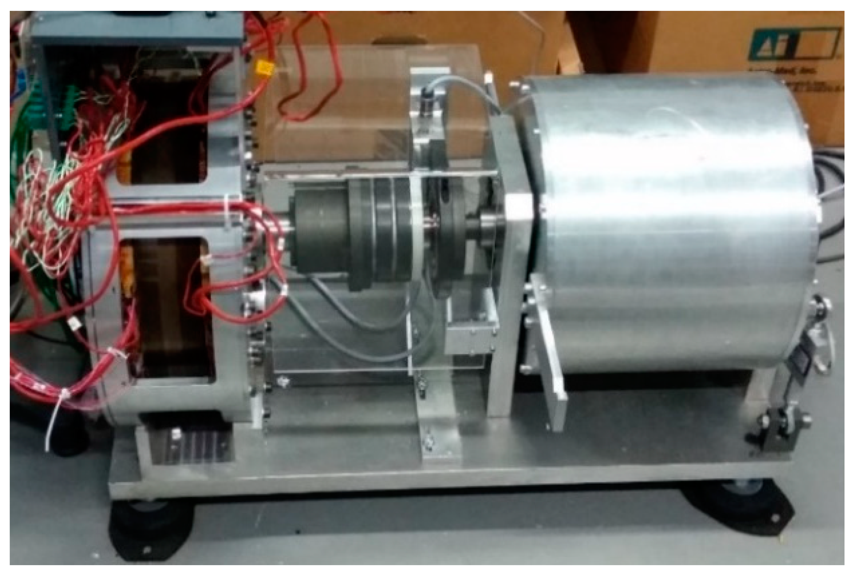
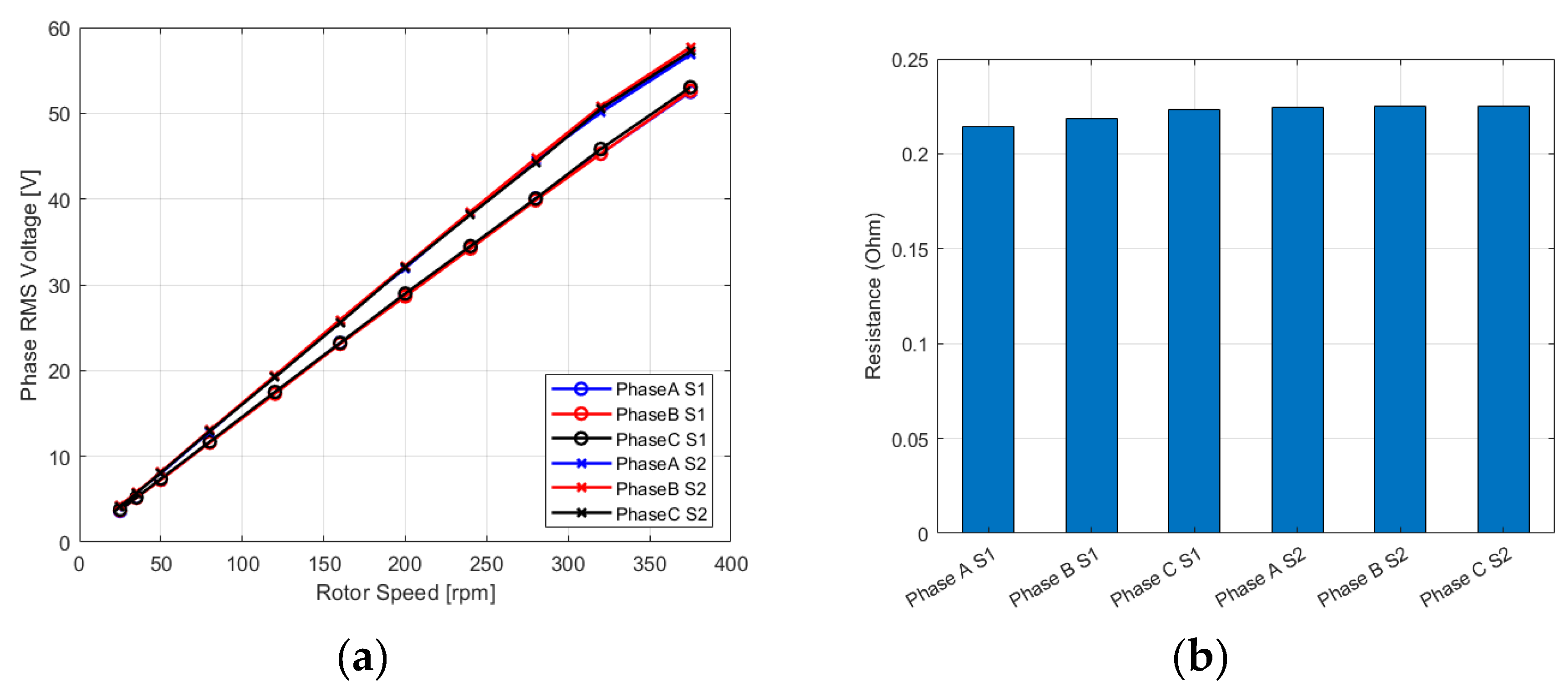
The AFSPM was connected to a prime mover (Figure 17), and a torque flange was mounted on the shaft connecting the generator to the prime mover to measure the speed and torque. The prime mover had its own motor drive, and its speed could be adjusted from 0 to 400 rpm. The basic open circuit performance was inspected for the machine (Figure 18a), and then the resistances of the phases’ windings were measured (Figure 18b).
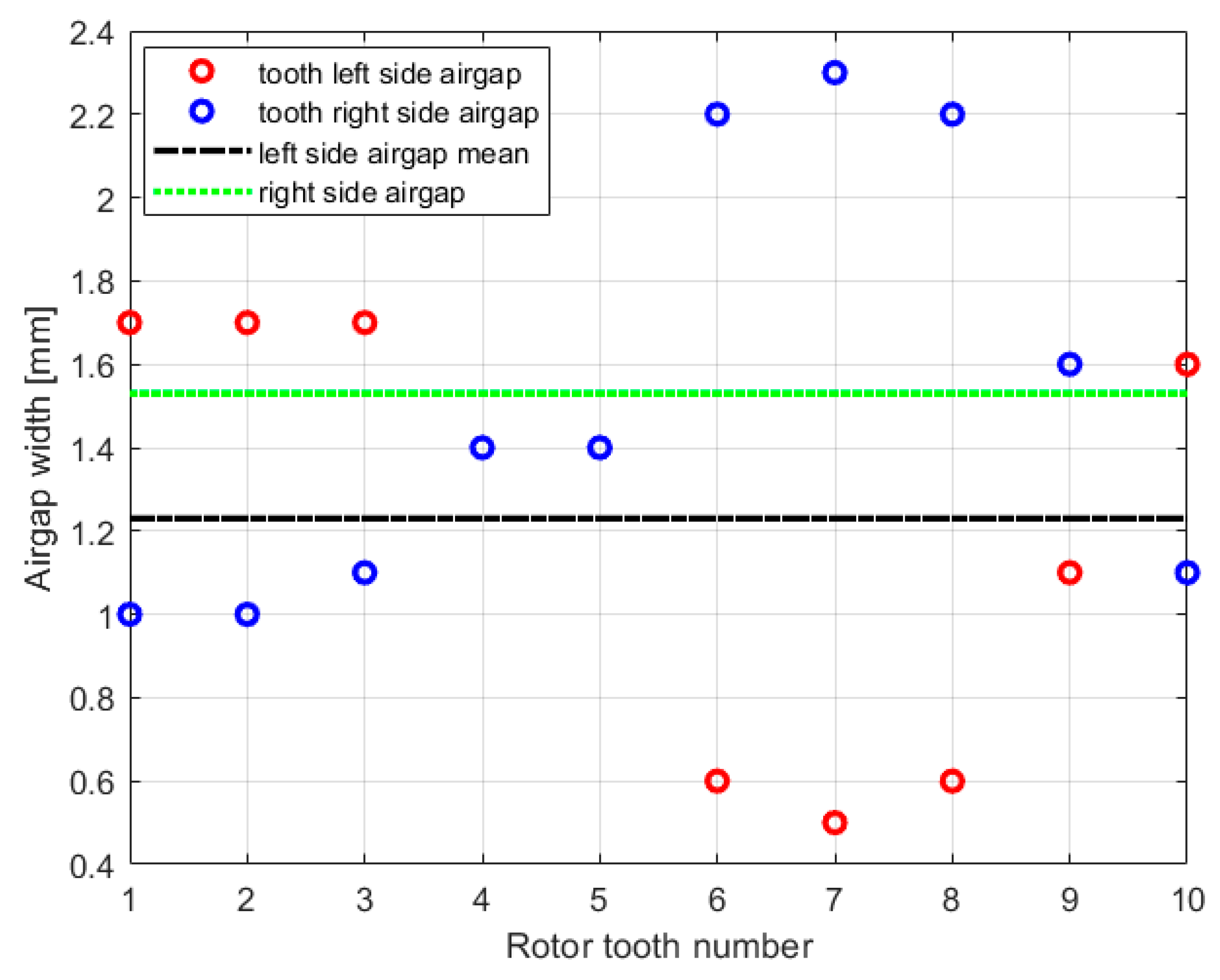
There was a slight voltage difference between the voltages of stator 1 and 2. Although both stators were constructed to be identical, the rotor, due to the large axial forces, suffered from a slight deflection, causing the airgap width to have different values across the circumference. The airgap width was measured on the left and right sides of each rotor tooth where the left-side width represents the air gap thickness between the rotor and stator 2, and the right-side width represents the air gap thickness between the rotor and stator 1 (Figure 19). Form Figure 19 it can be seen that the mean value of the air gap between stator 1 and the rotor was higher than that between stator 2 and the rotor, and the smaller airgap value means higher flux density values and, hence, higher EMF. Therefore, this may be the main reason causing the two stators to generate slightly different EMF values. The phases’ terminals from the two stators were meant to be connected in series; hence, the difference will not have any effect when the terminals are connected together. Experimental data were collected from a digital oscilloscope. The curves of the EMF of the three phases of each stator of the machine and the curves of the EMF when the stators’ terminals are connected in series are shown in Figure 20. The curves have the shape a pure sinusoidal wave.

5.1. Airgap Estimation

The airgap difference along the machine circumference will make it hard to compare the experimental results with the RN model theoretical results because the model will have only one airgap length value at a time. Hence, multiple RN models were constructed, each one having different airgap width, and then their results were compared to the experimental result, and Figure 21a illustrates this comparison. From the figure, the airgap width that seemed to have the nearest values to the experimental results was e = 2 mm. But again, we do not expect to get a perfect matching between the experimental and the RN model because this model is a 2D model and does not take into account the magnetic saturation of the materials. Figure 21b shows the comparison between the measured EMF values for the three phases and the generated EMF values using the 2D RN model with airgap width e = 2 mm.

5.2. Comparison between the AFSPM and the Axial Flux Surface Mounted Permanent Magnet Synchronous Machine

As mentioned in Section 3.1, many of the parameters of this machine were similar to those of a previously built machine prototype at GREAH. In order to get a better perspective on the machine under study, a detailed comparison was conducted between the two machines as a part of previous works at GREAH [10]. For this work only the comparison between the EMF waveforms will be shown (Figure 22).
It can be clearly seen that the EMF generated by the flux switching machine had a better shape and almost perfect sinusoidal waveform with almost zero harmonics, whereas the EMF generated by the surface mounted PM machine had a slight deformation and some harmonic components that, although they were small, were higher than those of the flux switching machine.

6. Discussion

Although the RN model proposed for the AFSPM is a 2D model and does not take into account the magnetic saturation of the ferromagnetic materials, by choosing a suitable value for the airgap thickness it performed well when comparing its results to the experimental results. So, the proposed model provided the advantage of being simple and reliable (to a certain level) at the same time. It can be mainly employed in predesign stages when variables are to be changed and the computation time is more important than the precision. A more complex 3D version of this model that takes into account the magnetic saturation would certainly give more accurate and precise results and can be used as a reliable final design stage model for AFSPMs. Moreover, it is clearer now that an RN model with a certain level of complexity can compete with FEM models in terms of accuracy and computation times.
Regarding the AFSPM prototype, the rotor suffered from a slight deflection causing a slight difference in the EMF of the phases of the two stators. The deflection is caused by the axial magnetic forces and the fact that the rotor comprises a stack of ferromagnetic sheets that can be considered weak in structure. A complete mechanical study was conducted on this machine in [10]. The EMF difference will not affect the operation of the machine because, typically, the phases of the two stators are connected in series, and the difference will not be noticed.

7. Conclusions

The work presented in this contribution is part of a larger project conducted at the GREAH laboratory aiming at comparing the performance of several machines’ technologies for renewable energy applications. The broader project aims at addressing the two basic aspects always faced when designing an electric machine: the choice of the adequate machine technology (axial field machine in this contribution) and the development of efficient design tools (modeling approach) for optimization purposes.
The paper started by introducing the flux switching and axial flux machines and their points of interest and followed by presenting the AFSPM prototype construction and specifications. Then, a 2D reluctance network magnetic model was proposed. The model was then validated by comparing its results to results from a 2D FEM model. The adopted modeling approach has proved to be efficient and gives good results as compared to the FEM. Finally, experimental study on the AFSPM prototype was presented, and the experimental results were compared to the results from the RN model proposed earlier. The open-circuit performance of the AFSPM has been compared to a previously developed SMPMAF prototype. This comparison study has shown that the EMF waveform is very close to a sinusoidal signal for the AFSPM, while the SMPMAF EMF contains more harmonics. This study is the first step, and a larger comparison study is still going, where the operation under load conditions is also considered.

Supplementary Materials

There is no supplementary information on the manuscript. The MATLAB program for the reluctance network model is available as a public repository at https://github.com/hdrdiab/RNM.git.

Author Contributions

Methodology: H.D. and Y.A.; Investigation: H.D.; Software, H.D.; Writing—original draft preparation, H.D.; writing—review and editing, Y.A.; supervision, Y.A. and G.B.; project administration, G.B. All authors have read and agreed to the published version of the manuscript.

Funding

This research received no external funding.

Conflicts of Interest

The authors declare no conflicts of interest.

Nomenclature

Φ i Flux through a branch in a magnetic circuit
Φ p m Flux source in a permanent magnet
Φ t Total flux for a certain phase
B r Permanent magnet remanence
P p m Permanent magnet permeability
R e x t Machine’s external radius
R i n t Machine’s internal radius
R μ i Reluctance of a branch in a magnetic circuit
U μ i The magnetic scalar potential between the nodes of a branch in a magnetic circuit
μ 0 Free space magnetic permeability ( 4 π 10 7   [ N . A 2 ] )
μ r p m Permanent magnet relative permeability
haPermanent magnet height
hcsStator yoke height
hdrRotor tooth height
hdsStator tooth height
herRotor slot height
hesStator slot height
LperiodMachine’s period length in the circumferential direction (x-direction in 2D)
LtotalMachine’s total length in the circumferential direction (x-direction in 2D)
waPermanent magnet width
wdrRotor tooth width
wdsStator tooth width
werRotor slot width
wesStator slot width
N r Number of rotor teeth
N s Number of stator slots

Appendix A

Figure A1. Flowchart of the 2D RN model software program.
Energies 13 00912 g0a1

References

  1. Andrada, P.; Martínez, F. Flux switching alternators for small wind generation. Renew. Energy Power Qual. J. 2016, 1, 678–683. [Google Scholar] [CrossRef]
  2. Xu, W.; Zhu, J.; Zhang, Y.; Guo, Y.; Lei, G. New Axial Laminated-Structure Flux-Switching Permanent Magnet Machine With 6/7 Poles. IEEE Trans. Magn. 2011, 47, 2823–2826. [Google Scholar] [CrossRef] [Green Version]
  3. Zhu, Z.Q.; Chen, J.T. Advanced Flux-Switching Permanent Magnet Brushless Machines. IEEE Trans. Magn. 2010, 46, 1447–1453. [Google Scholar] [CrossRef]
  4. Zhu, L.; Jiang, S.Z.; Zhu, Z.Q.; Chan, C.C. Analytical Methods for Minimizing Cogging Torque in Permanent-Magnet Machines. IEEE Trans. Magn. 2009, 45, 2023–2031. [Google Scholar] [CrossRef]
  5. Schulz, E.M.; Betz, R.E. Optimal torque per amp for brushless doubly fed reluctance machines. In Proceedings of the Fourtieth IAS Annual Meeting. Conference Record of the 2005 Industry Applications Conference, Hong Kong, China, 2–6 October 2005; Volume 3, pp. 1749–1753. [Google Scholar]
  6. Sitapati, K.; Krishnan, R. Performance comparisons of radial and axial field, permanent-magnet, brushless machines. IEEE Trans. Ind. Appl. 2001, 37, 1219–1226. [Google Scholar] [CrossRef]
  7. Chan, T.F.; Lai, L.L. An Axial-Flux Permanent-Magnet Synchronous Generator for a Direct-Coupled Wind-Turbine System. IEEE Trans. Energy Convers. 2007, 22, 86–94. [Google Scholar] [CrossRef]
  8. Chen, Y.; Pillay, P.; Khan, A. PM Wind Generator Topologies. IEEE Trans. Ind. Appl. 2005, 41, 1619–1626. [Google Scholar] [CrossRef] [Green Version]
  9. Parviainen, A.; Pyrhonen, J.; Kontkanen, P. Axial Flux Permanent Magnet Generator with Concentrated Winding for Small Wind Power Applications. In Proceedings of the IEEE International Conference on Electric Machines and Drives, San Antonio, TX, USA, 15 May 2005; pp. 1187–1191. [Google Scholar]
  10. Dhifli, M. Contribution au Développement de Structures Discoïdes de Machines Électriques à Aimants Permanents à Commutation de Flux Pour la L’éolien, Université du Havre; Normandie Université: Caen, France, 2016. [Google Scholar]
  11. Azzouzi, J. Modeling and Optimisation of Axial Flux Permanent Magnet Synchronous Machine for Wind Energy Application. Ph.D. Thesis, Université du Havre, Le Havre, France, 2007. [Google Scholar]
  12. Tiegna, H. Contribution à la Modélisation Analytique des Machines Synchrones à Aimants Permanents, à Flux Axial, à Entraînement Direct en Vue de Leur Dimensionnement: Application Aux Éoliennes; Université du Havre: Le Havre, France, 2013. [Google Scholar]
  13. Ennassiri, H. Magneto-Vibro-Acoustic Analysis of Synchronous Permanent Magnet Machines Dedicated to Electric Hybrid Vehicles. Ph.D. Thesis, Normandie Université, Caen, France, 2018. [Google Scholar]
  14. Hao, L.; Lin, M.; Li, W.; Luo, H.; Fu, X.; Jin, P. Novel Dual-Rotor Axial Field Flux-Switching Permanent Magnet Machine. IEEE Trans. Magn. 2012, 48, 4232–4235. [Google Scholar] [CrossRef]
  15. Chen, J.T.; Zhu, Z.Q. Winding Configurations and Optimal Stator and Rotor Pole Combination of Flux-Switching PM Brushless AC Machines. IEEE Trans. Energy Convers. 2010, 25, 293–302. [Google Scholar] [CrossRef]
  16. Rauch, S.E.; Johnson, L.J. Design Principles of Flux-Switch Alternators [includes discussion]. Trans. Am. Inst. Electr. Eng. Part III Power Appar. Syst. 1955, 74, 4499226. [Google Scholar] [CrossRef]
  17. Hoang, E.; Ben Ahmed, H.; Lucidarme, J. Switching flux permanent magnet polyphased synchronous machines. In Proceedings of the EPE 97, Trondheim, Norway, 8–10 September 1997. [Google Scholar]
  18. Boisson, J. Analytical Approach for Magnetic, Mechanical and Acoustic Modeling of Flux-Switching Permanent-Magnet Motors: Application to Geometrical Optimization. Ph.D. Thesis, École normale supérieure de Cachan—ENS Cachan, Cachan, France, 2014. [Google Scholar]
  19. VEREZ, G. Contribution to the Study of Vibro-Acoustic Emissions of Electrical Machines. Case of the Permanent Magnet Synchronous Machines for Automotive Applications. Ph.D. Thesis, Université du Havre; Normandie Université, Caen, France, 2014. [Google Scholar]
  20. Shen, J.-X.; Fei, W.-Z. Permanent magnet flux switching machines – Topologies, analysis and optimization. In Proceedings of the 4th International Conference on Power Engineering, Energy and Electrical Drives, Istanbul, Turkey, 13–17 May 2013; pp. 352–366. [Google Scholar]
  21. Ilhan, E.; Kremers, M.F.J.; Motoasca, E.T.; Paulides, J.J.H.; Lomonova, E.A. Sensitivity analysis for phase inductances in Flux-Switching PM machines. In Proceedings of the 2012 XXth International Conference on Electrical Machines, Marseille, France, 2–5 September 2012; pp. 763–768. [Google Scholar]
  22. Hao, L.; Lin, M.; Zhao, X.; Fu, X.; Zhu, Z.Q.; Jin, P. Static Characteristics Analysis and Experimental Study of a Novel Axial Field Flux-Switching Permanent Magnet Generator. IEEE Trans. Magn. 2012, 48, 4212–4215. [Google Scholar] [CrossRef]
  23. Chen, J.T.; Zhu, Z.Q.; Howe, D. Stator and Rotor Pole Combinations for Multi-Tooth Flux-Switching Permanent-Magnet Brushless AC Machines. IEEE Trans. Magn. 2008, 44, 4659–4667. [Google Scholar] [CrossRef]
  24. Chen, J.T.; Zhu, Z.Q. Comparison of All- and Alternate-Poles-Wound Flux-Switching PM Machines Having Different Stator and Rotor Pole Numbers. IEEE Trans. Ind. Appl. 2010, 46, 1406–1415. [Google Scholar] [CrossRef]
  25. Chen, J.T.; Zhu, Z.Q. Influence of the Rotor Pole Number on Optimal Parameters in Flux-Switching PM Brushless AC Machines by the Lumped-Parameter Magnetic Circuit Model. IEEE Trans. Ind. Appl. 2010, 46, 1381–1388. [Google Scholar] [CrossRef]
  26. Sikder, C.; Husain, I.; Ouyang, W. Cogging Torque Reduction in Flux-Switching Permanent-Magnet Machines by Rotor Pole Shaping. IEEE Trans. Ind. Appl. 2015, 51, 3609–3619. [Google Scholar] [CrossRef]
  27. Hua, W.; Cheng, M.; Zhu, Z.Q.; Howe, D. Analysis and Optimization of Back-EMF Waveform of a Novel Flux-Switching Permanent Magnet Motor. In Proceedings of the 2007 IEEE International Electric Machines & Drives Conference, Antalya, Turkey, 3–5 May 2007; pp. 1025–1030. [Google Scholar]
  28. Dhifli, M.; Ennassiri, H.; Amara, Y.; Barakat, G. Impact of the airgap magnetic field harmonics on the performances of a disc type flux switching machine for wind application. In Proceedings of the 2016 XXII International Conference on Electrical Machines (ICEM), Lausanne, Switzerland, 4–7 September 2016; pp. 2431–2437. [Google Scholar]
  29. Sykulski, J.K. Computational Magnetics; Springer: Dordrecht, The Netherlands, 1995; ISBN 978-94-011-1278-9. [Google Scholar]
  30. Aden, A.; Amara, Y.; Barakat, G.; Hlioui, S.; De La Barriere, O.; Gabsi, M. Modeling of a radial flux PM rotating machine using a new hybrid analytical model. In Proceedings of the 2014 International Conference on Electrical Sciences and Technologies in Maghreb (CISTEM), Tunis, Tunisia, 3–6 November 2014; pp. 1–5. [Google Scholar]
  31. Benhamida, M.A.; Ennassiri, H.; Amara, Y.; Barakat, G.; Debbah, N. Study of switching flux permanent magnet machines using interpolation based reluctance network model. In Proceedings of the 2016 International Conference on Electrical Sciences and Technologies in Maghreb (CISTEM), Marrakech, Morocco, 26–28 October 2016; pp. 1–7. [Google Scholar]
  32. Marinescu, M.; Marinescu, N. Numerical computation of torques in permanent magnet motors by Maxwell stresses and energy method. IEEE Trans. Magn. 1988, 24, 463–466. [Google Scholar] [CrossRef]
  33. Reddy, J.N. An Introduction to the Finite Element Method, 3rd ed.; Oxford Univ. Press: Oxford, UK, 2006; p. 13. [Google Scholar]
Figure 1. (a) Demonstration of the stator windings; (b) photo of the windings of the prototype.
Energies 13 00912 g001
Figure 2. The AFSPM winding configuration ABC-ABC.
Energies 13 00912 g002
Figure 3. Prototype assembly: (a) before inserting the permanent magnets (PMs) and adding the outer carcass; (b) with the outer carcass installed.
Energies 13 00912 g003
Figure 4. AFSPM geometry with symmetry and periodicity conditions: (a) full machine geometry; (b) geometry to be modeled after applying anti-symmetry and cyclic boundary conditions.
Energies 13 00912 g004
Figure 5. 2D plan schematic of the rotor and stator of the AFSPM: (a) stator period bottom view where the red represents the stator PM, the green represents the stator slots, and the grey represents the stator teeth; (b) rotor period bottom view where the grey represents the rotor teeth, and the green represents the rotor slots.
Energies 13 00912 g005
Figure 6. Annotations for the dimensions of the AFSPM linear structure.
Energies 13 00912 g006
Figure 7. Axial field surface mounted permanent magnet synchronous machine prototype designed at GREAH: (a) assembled stator view; (b) the full machine assembly.
Energies 13 00912 g007
Figure 8. (a) Variation of the cogging torque in function of rotor tooth width; (b) variation of mean electromagnetic torque in function of rotor tooth opening.
Energies 13 00912 g008
Figure 9. Meshed AFSPM linear structure.
Energies 13 00912 g009
Figure 10. (a) Reluctance element used for 2D problems; (b) the rectangular parallelepiped PM region.
Energies 13 00912 g010
Figure 11. Demonstration on the motion simulation process through reluctance manipulation. Each color represents a certain reluctance value and is added just for illustration: (a) initial position of the nodes and their connected reluctances; (b) the new reluctance distribution after one step rotor movement.
Energies 13 00912 g011
Figure 12. 2D FEM linear model geometry created by FLUX: (a) the complete geometry without meshing; (b) the complete geometry with meshing
Energies 13 00912 g012
Figure 13. Comparison between the results from the 2D RN and 2D FEM: (a) total Magnetic flux per phase; (b) voltage EMF per phase considering the machine running at 375 rpm.
Energies 13 00912 g013
Figure 14. Frequency spectrum analysis of the results: (a) frequency spectrum of the magnetic flux curves generated by the 2D RN and 2D FEM; (b) frequency spectrum of the EMF curves generated by the 2D RN and 2D FEM.
Energies 13 00912 g014
Figure 15. Comparison between the results from the 2D RN and 2D FEM: (a) magnetic induction x component in the airgap (tangential component); (b) magnetic induction y component in the airgap (normal component).
Energies 13 00912 g015
Figure 16. Comparison between the cogging torque results generated by the 2D RN and 2D FEM models.
Energies 13 00912 g016
Figure 17. Assembled AFSPM prototype connected to the prime mover.
Energies 13 00912 g017
Figure 18. Results from the electric measurements done on the prototype. (a) Open circuit tests: the RMS voltage per phase per stator in function of the speed in rpm; (b) resistance values per phase per stator.
Energies 13 00912 g018
Figure 19. Airgap width values measured on the left and right sides of each rotor tooth.
Energies 13 00912 g019
Figure 20. Experimental measurement curves of the EMF of the three phases: (a) when the phases of the two stators are disconnected from each other; (b) when the phases of the two stators are connected in series.
Energies 13 00912 g020
Figure 21. Comparison between the measured EMF values and the model generated ones. (a) Illustration on the airgap estimation study where the generated EMF from different RN models with different airgap width values were compared to the measured EMF value. (b) The 3 phases EMF generated from the RN model having the air gap width e = 2 mm compared to the measured 3 phases EMF.
Energies 13 00912 g021
Figure 22. Comparison between the EMF generated by the surface mounted PM machine (SM) and the flux switching machine (FSM). (a) Measured EMF waveforms of both machines. (b) Frequency spectrum of the measured EMF waveforms of the two machines.
Energies 13 00912 g022
Table 1. The design variables describing the AFSPM prototype.
Parameter NameValue (Unit)Parameter NameValue [Unit]
Electric Power10 (Kw)Magnet height (ha)35 (mm)
Nominal rotation speed375 (rpm)Stator slot width (wes)6.25 (°)
StructureS-R-SStator slot height (hes)25 (mm)
No of stator slots/No of rotor teeth12/10Air gap at each side (e)1.5 (mm)
Magnets TypeNdFeBRotor teeth width (wdr)15 (°)
Remanence (Br)1.2 (T)Rotor tooth height (hdr)35 (mm)
Stator interior radius (Rint)133 (mm)Rotor slots (openings) width (wer)21 (°)
Stator exterior radius (Rext)186 (mm)Rotor slot height (her)25 (mm)
Stator tooth height (hds)35 (mm)Axial Length142 (mm)
Stator tooth width (wds)8.75 (°)
Stator yoke height (hcs)10 (mm)Stator MaterialFer-Silicium M270-50A
Magnet width (wa)6.25 (°)Rotor MaterialM270-35A