Abstract
Due to the working condition of low-voltage cabling from the mining flameproof movable substation to the loads of the mining face being poor, it is easy to cause various external mechanical damages to the cable sheaths. Furthermore, a single-phase earth leakage fault or short-circuit fault can occur when the low-voltage cable sheaths are damaged, and electric sparks caused by these faults can lead to a gas explosion. As the gas detonation time caused by the above faults is usually more than 5 ms, the high-speed interruption solid-state switch which controls the cables must cut off the current within 3 ms. This requires the action time of the solid-state switch to be less than 1 ms, and at the same time, the sampling and calculation time of the relay protection must be less than 2 ms. Based on these problems, this paper proposes the use of a high-speed solid-state circuit breaker (SSCB) topology at the neutral point of transformer, and analyzes the conduction mechanism and shut-off mechanism of the current of the SSCB. It presents an ultra-high-speed algorithm based on pattern recognition of single-phase earth leakage fault protection, and an ultra-high-speed algorithm of short-circuit fault which is based on the rate-of-change of the current. Finally, through computer simulation experiments and semi-physical simulation experiments, the feasibility of the above three technologies is verified to ensure that when a single-phase earth leakage fault or short-circuit fault occurs in the low-voltage cable, the solid-state switch which is installed in the mining flameproof movable substation will cut off the current within 3 ms.
1. Introduction
The safety technology for high-speed interruption employs a variety of methods and techniques to prevent electrical fires which can occur when an earth leakage fault or short-circuit fault creates a breakdown or electric spark which ignites a surrounding explosive or flammable medium [1]. A great deal of experimental data [2,3,4] demonstrates how cable sheaths which are damaged by various external mechanical means can shunt a single-phase earth leakage fault or cause a short circuit, and subsequently cause a leakage spark and/or short-circuit arc, which can then cause a gas explosion. The total fault formation time requires more than 5 ms [5], and therefore the guiding principle of “safety technology for high-speed interruption” can be expressed as:
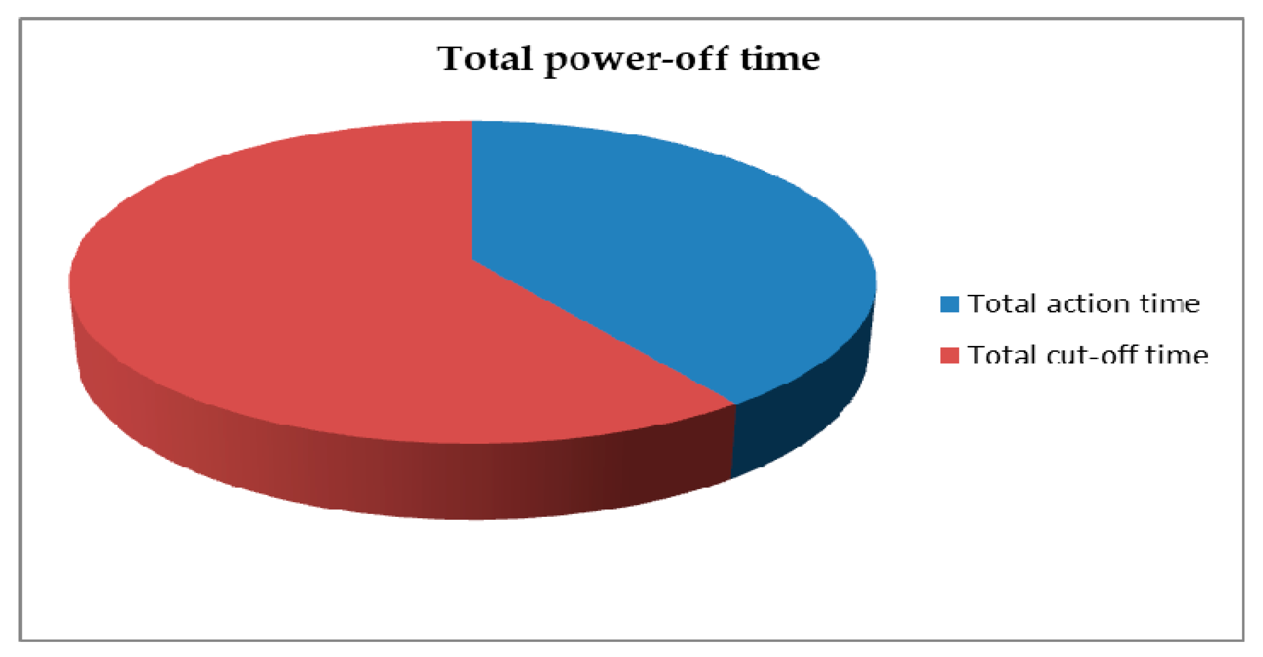
where T0 = total power-off time; and TF = fault formation time.
Safety technology for high-speed interruption is comprised of two components, protection relay technology and high-speed interruption switch technology [6,7,8]. A high-speed interruption protection relay uses the technology of high-speed sampling, digital signal processing, and computer algorithms in order to implement the apparatus which can enable a protection relay total action time to be less than 3 ms. Total action time refers to the entire time from the moment when the electrical fault occurs to when the switch is commanded to interrupt the power. The high-speed interruption switch is a solid-state device which uses ultra-high-speed switching technology and components in order to ensure that the total cut-off time of the switch (TC) is less than 2 ms. The relationship between total action time (TA), total cut-off time (TC), and total power-off time (T0) is demonstrated in Figure 1. If the total power-off time is less than 5 ms, it is possible to achieve the safety goal of fire- and explosion-proofing the entire feed-out power supply system, which includes all electrical equipment and power cables.

Figure 1.
Power-off times.
In recent years, the rapid development of computer technology, data conversion and the significant improvement of calculation speeds have facilitated the research, development, and implementation of digital high-speed relay protection systems.
This paper reports on theoretical and experimental research in three areas of the safety technology for the high-speed interruption field, namely ultra-high-speed earth leakage protection, ultra-high-speed short-circuit protection, and fast interruption solid-state circuit breakers (SSCBs). We demonstrate that such a system is feasible using todays technology.
2. Background
2.1. Solid-State Circuit Breaker-Neutral (SSCB-N)
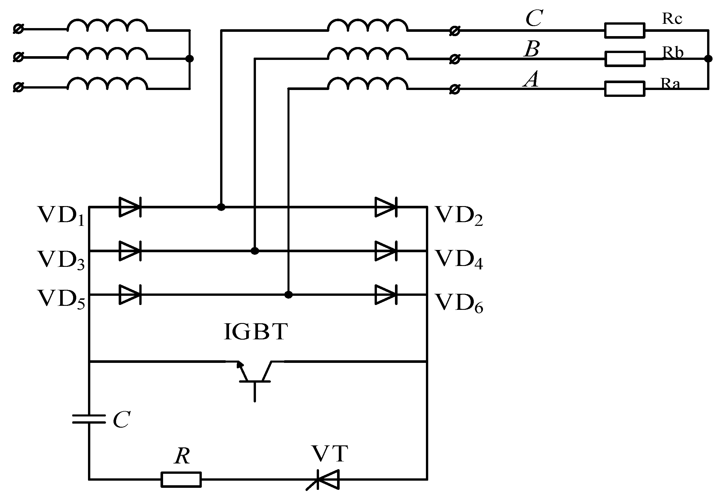
In order to achieve the technical target of T0 < 5 ms, this paper presents the topology for a high-speed interruption solid-state circuit breaker–neutral (SSCB–N) circuit (see Figure 2). The secondary-side neutral point of a three-phase transformer is controlled by a SSCB–N, which uses an insulated-gate bipolar transistor (IGBT) to realize both the connection and interruption. When the SSCB–N conducts, the secondary coil of the transformer supplies power to the load; when the SSCB–N shuts off, the transformer ceases to supply power. The basic concept behind this switch is to control the AC current through the loads by switching the IGBT off and on. This switch can quickly isolate a fault and can also prevent potential damage due to operating at overvoltage in the system. It does this by converting the three-phase AC switching technology into a single-phase DC equation, changing the zero-crossing natural shutdown of the AC switch into forced shutdown of the DC switch, and reducing the overvoltage caused by di/dt through RC snubber circuit, eventually realizing natural shutdown when the second-order circuit current crosses the zero point [9].
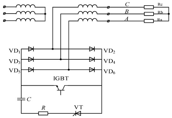
Figure 2.
Neutral point switch circuit topology constituting by solid-state breaker.
As shown in Figure 2, the current will through the snubber circuit which consists of the VT (i.e., VT is thyristor which is used to cut off the surge current in the snubber), R and C (i.e., R and C are used to absorb energy of the surge current in the snubber circuit) after the interruption of the IGBT. So the SSCB-N will cut off the power after the shutdown of the VT.
As shown in Figure 3, we define the t = 0 as the moment of the interruption of the IGBT, and through analyses of the conduction mechanism and shut-off mechanism of the current of the SSCB-N, we can get the cut-off time of VT (t2off) as follows:
and
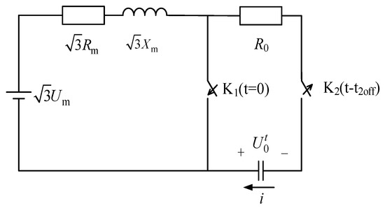
Figure 3.
Equivalent diagram at the moment of IGBT off.
The cut-off time of the SSCB-N equation can be written as:
where t1off is the cut-off time of the IGBT.
We can get the t2off and the Tk when we bring the electrical parameters into Equations (2) and (4). For example, the electrical parameters of the 100 kVA/660 V mining flameproof movable substation as follow:
Then we bring these parameters into Equation (5), we obtain , and .
Through parameter optimization and design, computer simulation, and experimental measurements, the SSCB–N circuit can be realized, so that it has a certain shut-off maximum short-circuit current, minimum two-phase short-circuit current, and total cut-off time with no-load current less than 1 ms. The specific operational principle, topology, and mathematical model of the SSCB–N can be seen in [9].
When a short circuit occurs in a power supply system, the SSCB–N can cut it off immediately before it reaches peak value. Therefore, the current-limiting properties of the SSCB–N will reduce damage to the power supply system and its associated electrical equipment which would be caused by the short-circuit current.
2.2. Ultra-High-Speed Single-Phase Earth Leakage Protection
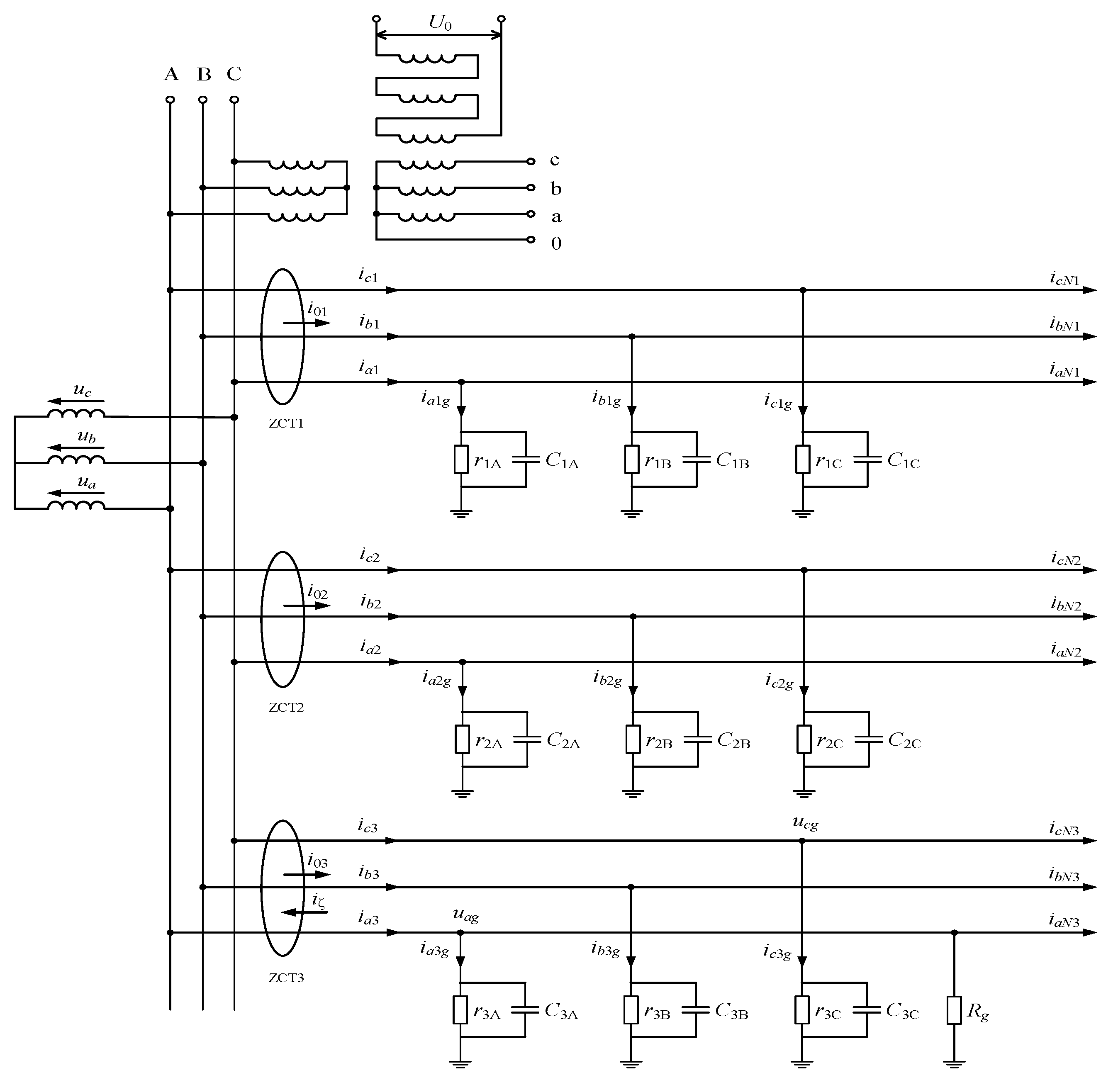
The electrical principle behind a single-phase earth leakage fault is shown in Figure 4, in which the distributed parameters of the cables are primarily composed of distributed capacitance and insulation resistance with respect to the ground [10]. Ordinary single-phase earth leakage protection technology [11,12,13,14,15] cannot satisfy the time requirement for high-speed interruption. Through sampling zero-sequence voltage and zero-sequence current, this paper describes an ultra-high-speed single-phase earth leakage protection algorithm based on a pattern-recognition method.

Figure 4.
Single-phase earth leakage thumbnail Figure in a no-grounding system and its sampling method.
Based on Thevenin’s theorem, the single-phase earth leakage equivalent diagram from Figure 4 is shown in Figure 5:
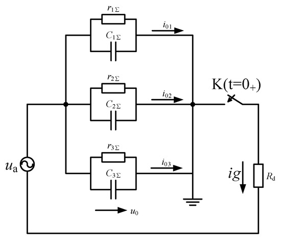
Figure 5.
Single-phase earth leakage equivalent diagram.
As shown in Figure 4, the zero-sequence current i0i for each branch can be sampled using a zero-sequence current transformer ZCTi (i = 1, 2, 3). The non-fault branch differential equation can be written as:
where Ci is the distributed capacitance to the ground for each phase of each branch i, assuming that the three-phase distributed capacitances to the ground are equal, is the three-phase equivalent insulation resistance to the ground for each branch i, and u0 is zero-sequence voltage. Equation (6) can be rewritten as a difference equation, the difference spacing can be assumed as T without the loss of generality, and four consecutive samples are marked as k, k + 1, k + 2, k + 3:
Equation (6) has only two unknown variables and , so if we sample consecutively four times we can determine these two unknown variables. That is:
The pattern recognition procedure begins when the zero-sequence current has a single-phase earth leakage fault. Initially, it should be assumed that every cable is in normal condition (i.e., without single-phase earth leakage fault fault), then we calculate the three-phase equivalent insulation resistance to the ground and distributed capacitance to the ground of the ith phase . For example, in Branch 1, if the calculated values of and are logical (i.e., the distributed parameters of this branch are logical), then it can be determined that there is no single-phase earth leakage fault. If the calculated values of and are illogical (i.e., all negative values), this means that the distributed parameters of this branch do not conform with the model. That is to say, the hypothesis that “there is no single-phase earth leakage fault in this branch” is incorrect, which means that an earth leakage fault of branch 1 has occurred.
There are two unique features of this method: (1) the calculation speed can be changed by adjusting the sampling interval time, T, and (2) it determines whether the branch has a single-phase earth leakage fault only through the positive or negative value. Combined with the proposed high-speed SSCB–N hardware, this method can quickly determine (within 2 ms) which branch has a single-phase earth leakage fault, and which trips the system and cuts off power straight away. Specific elements will be outlined in Section 3 and Section 4 through computer simulation and semi-physical simulation experiment.
2.3. Ultra-High-Speed Short-Circuit Protection
Firstly, in order to quickly and accurately detect the fault, we need to understand the change rules of the short-circuit currents when the currents are in the transient process [16,17,18]. Secondly, we also should understand the characteristics of the motor-starting current so that our system does not incorrectly trigger.
2.3.1. Rate of Change of the Short-Circuit Current
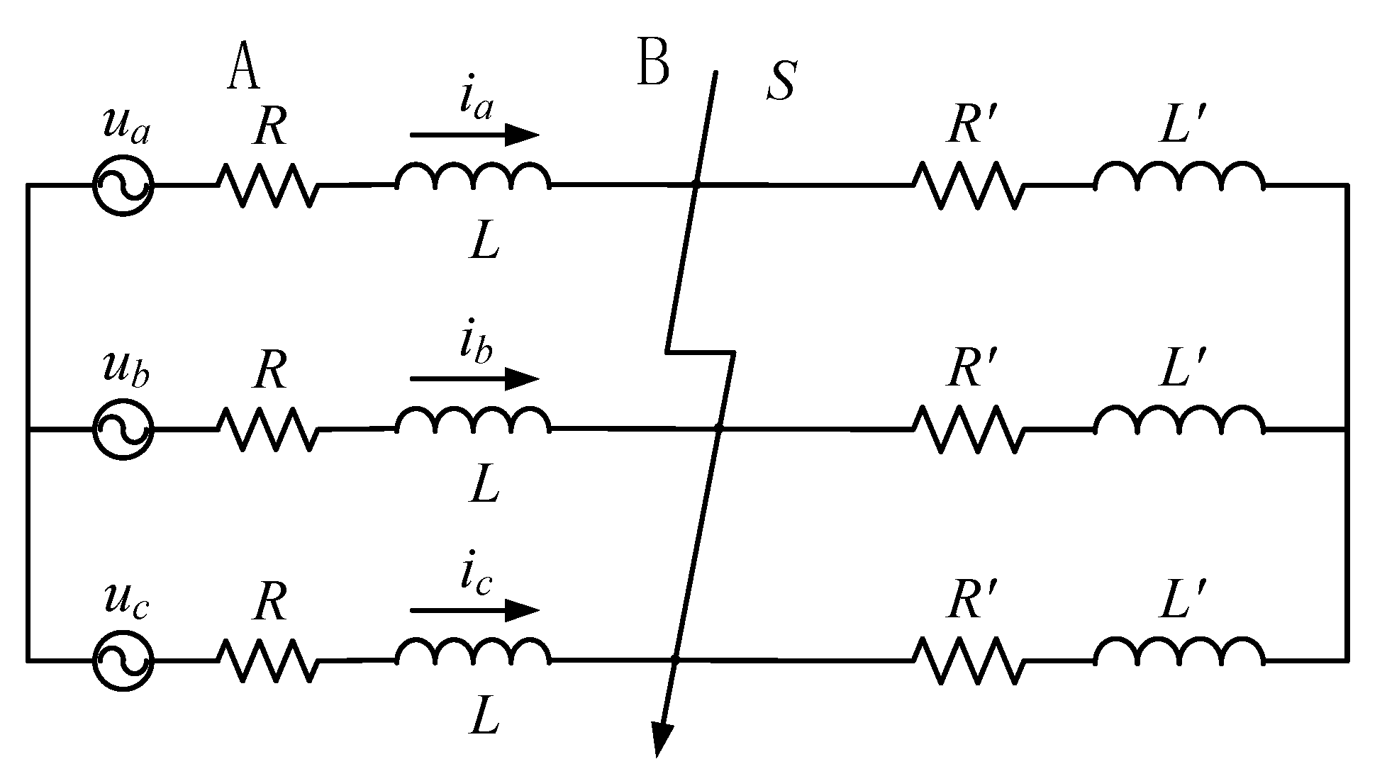
Figure 6 is a three-phase diagram which is presented when the power system has a short-circuit. A is the power supply side that supplies power to side B. The bus voltage and current at side A is:
and
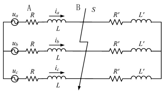
Figure 6.
Three-phase short circuit.
We start by examining at a situation in which a three-phase short-circuit fault occurs. This means that the load impedance is short-circuited and its current has increased suddenly due to the short-circuit current, so:
and
- is the periodic component amplitude of the short-circuit current, , A.
- is the impedance of the short-circuit branch, .
- is the amplitude of the load current before short-circuit occurrence, A.
- is the impedance angle of the loop of the short-circuit, , rad.
- is the initial phase angle of the voltage at the time of short-circuit occurrence, rad.
- is the time constant of short-circuit loop, , s.
If we differentiate Equation (14), we obtain the following expression for the rate of change of the short-circuit current:
And we can use this rate-of-change of the current as the setting for the short-circuit protection.
2.3.2. Rate of Change of the Motor Starting Current
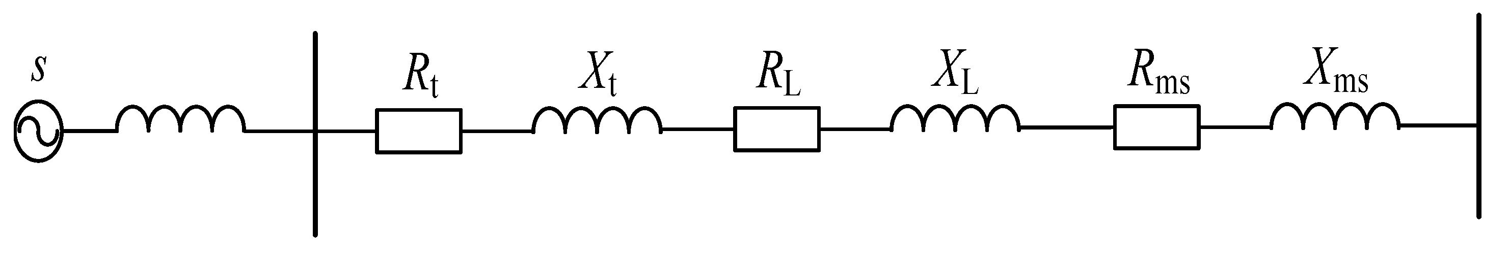
Due to the type of the motor (i.e., three-phase asynchronous induction motor) at the mining face, the instantaneous equivalent circuit of a motor starting is shown in Figure 7. If we use as the coefficient for the peak value of the load current , and define the steady-state maximum short-circuit current as , then ( < 1). The starting current is
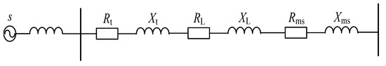
Figure 7.
Equivalent circuit of motor starting.
In Equation (16) the as follows:
If we define the load current before starting as , then
- is the peak value of motor starting current, A.
- is the initial phase angle of phase voltage, rad.
- is the impedance angle of starting loop, rad.
- is the time constant of starting loop, , s.
Differentiating Equation (18) we obtain the rate-of-change of the motor starting current as
If we set , then
The starting current of the motor is usually the 5–10 times rated current, the fault action of the protection often occur at this moment. So the basic premise behind using the rate-of-change of the short-circuit current is to calculate the rate-of-change of the current in real time and set to correspond to the rate-of-change of the short-circuit current in order that it can be differentiated from the rate-of-change of the motor starting current . To determine which value to set for the rate-of-change and how to indicate that a fault has occurred, we must perform experiments and simulations. These are described below.
3. The Verification the Algorithm
3.1. Ultra-High-Speed Earth Leakage Protection
In order to verify the validity of the previously mentioned parameter identification method, we must first establish a power supply system with five branches, each branch having different distribution parameters to the ground, and simulate the general circumstances and all kinds of extreme circumstances of the actual system. For example, the model of single-phase earth leakage fault of five branches is shown in Figure 8.
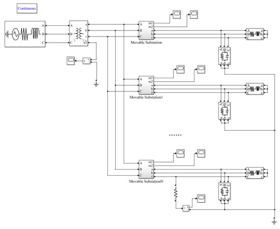
Figure 8.
The simulation model.
The MATLAB parameter is set as T = 10 μs, the transformer ratio is 6 kV/660 V, and the simulation algorithm is ode23t.
Due to limited space, only part of the parameters of single-phase earth leakage fault are listed in Table 1, Table 2 and Table 3. We can see that the calculated values of the insulation resistance to the ground and distributed capacitance to the ground from branch 1 to 4 are all positive, and the parameters of distributed capacitance are very close to the actual settings. This shows that the distribution parameters are normal, or single-phase earth leakage fault has not occurred. However the distribution parameters of the fifth branch are all negative, which indicates that the distribution parameters do not conform with the model, and from this we can see that earth leakage fault has occurred in this branch ( is the grounding resistance when the single-phase earth leakage fault occurs, which shown in Figure 4).

Table 1.
The result of the emulate when the extreme circumstance of single-phase earth leakage fault occurred (). (resistance: kΩ; capacitance: μF; time: ms).
Table 2.
The result of the emulate when the extreme circumstance of single-phase earth leakage fault occurred (). (resistance: kΩ; capacitance: μF; time: ms).
Table 3.
The result of the emulate when the extreme circumstance of single-phase earth leakage fault occurred (). (resistance: kΩ; capacitance: μF; time: ms).
3.2. Ultra-High-Speed Short-Circuit Protection
According to the transient analysis of motor starting current, when the motor starts, the maximum current is 1.4 times the peak value of the steady state current. Make , the steady-state amplitude of the short-circuit current , in which is the sensitivity coefficient of traditional over-current protection, ≥ 1.5. The short-circuit fault might occur at the secondary winding of transformer, or may also occurs at the end of the cable, therefore, if the R and L are different at the short-circuit loop, the amplitude of the short-circuit current is also different, meaning that is different. In addition, at the exact moment of short-circuit fault occurs, the initial phase of phase voltage affects the rate of the waveform of the short-circuit current, which also affects the sampling time. Therefore, we must calculate all the sampling time according to = 0–180°, and determine the maximum time as the sampling time where certain circuit parameters, such as and remain unchanged. Later we will aim at the determined setting in order to calculate which is the time from reaches when = 0.01–0.99 and = 1.5–3.5.
When the rate-of-change of the current is considered as the sampling value, we must firstly determine the maximum rate-of-change the linear current in the normal working system, and then use this as the action setting , and finally determine .
According to the method, we differentiate Equation (18), making , according to different and different we can have a different extremum , which can be placed into Equation (19). In order to obtain the extremum rate-of-change of the motor starting current and make a comparison to determine and finally. As we only considered of the maximum value, can be calculated using a computer, and if we search from point to point we can determine the maximum, the moment which it appears and the corresponding initial phase angle .
From Table 4 we can see that the situation when the maximum rate-of-change of the starting current appears is opposite that from which the maximum starting current appears, the higher the and the greater the , the lower the and the smaller the . That is to say, the reactance of circuits plays a limited role in the rising speed of current. With the same circuit parameters, as equals, the larger the and the smaller the . Therefore, before starting when the circuit is without a load, the rate-of-change of the starting current is at its greatest. When = 0.5, = 1.15.
Table 4.
The derivatives of start current with different load moduli.
Based on the above analysis, make the action setting, we use the same method to analyze the action time of this type of protection, and the calculated results are listed in Table 5.
Table 5.
Sample time with the criterion by , ms.
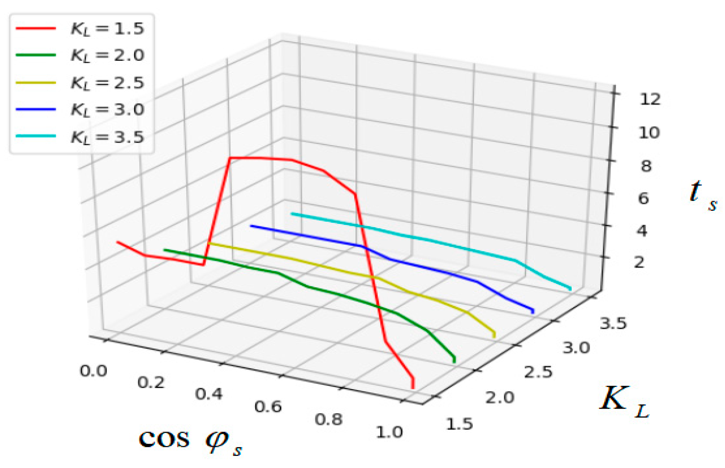
As we can see from Table 5, when = 1.5, > 0.9, the action time can achieve the requirement < 3 ms. When = 2.0, the critical value of is 0.5. When > 2.5, no matter the value of , the sampling time is less than 2.6 ms. The relationship between total action time TA, power factor and sensitivity coefficient is shown in Figure 9.

Figure 9.
The relationship between , and with the sampling method of .
Generally, when a short-circuit fault occurs in the cable, the time constant is . The criterion for ultra-high-speed short-circuit protection is that when the average of calculated by multiple consecutive sampling points is greater than the action setting, that is , and , it can be determined that the short-circuit fault has occurred in this branch.
4. Experiments
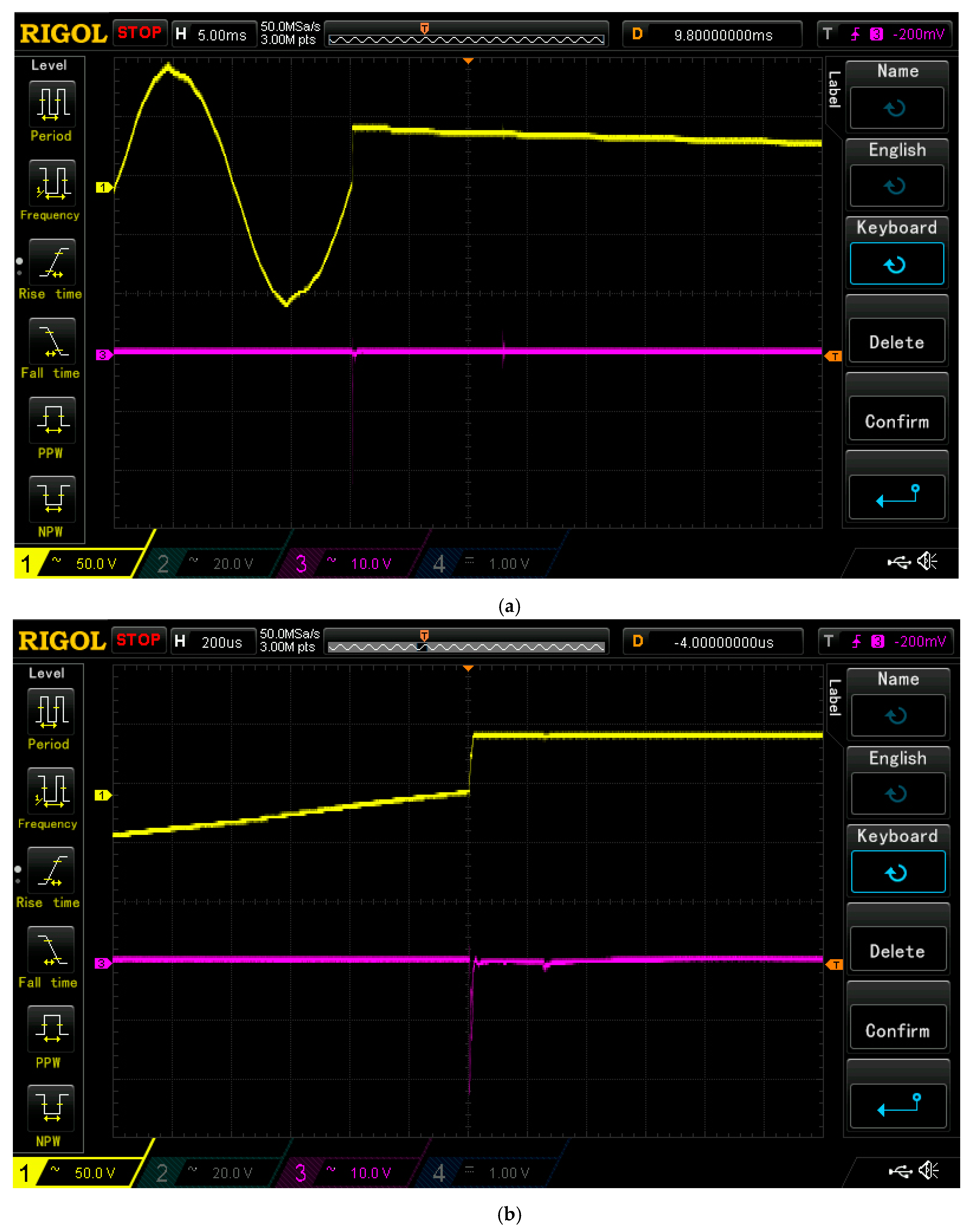
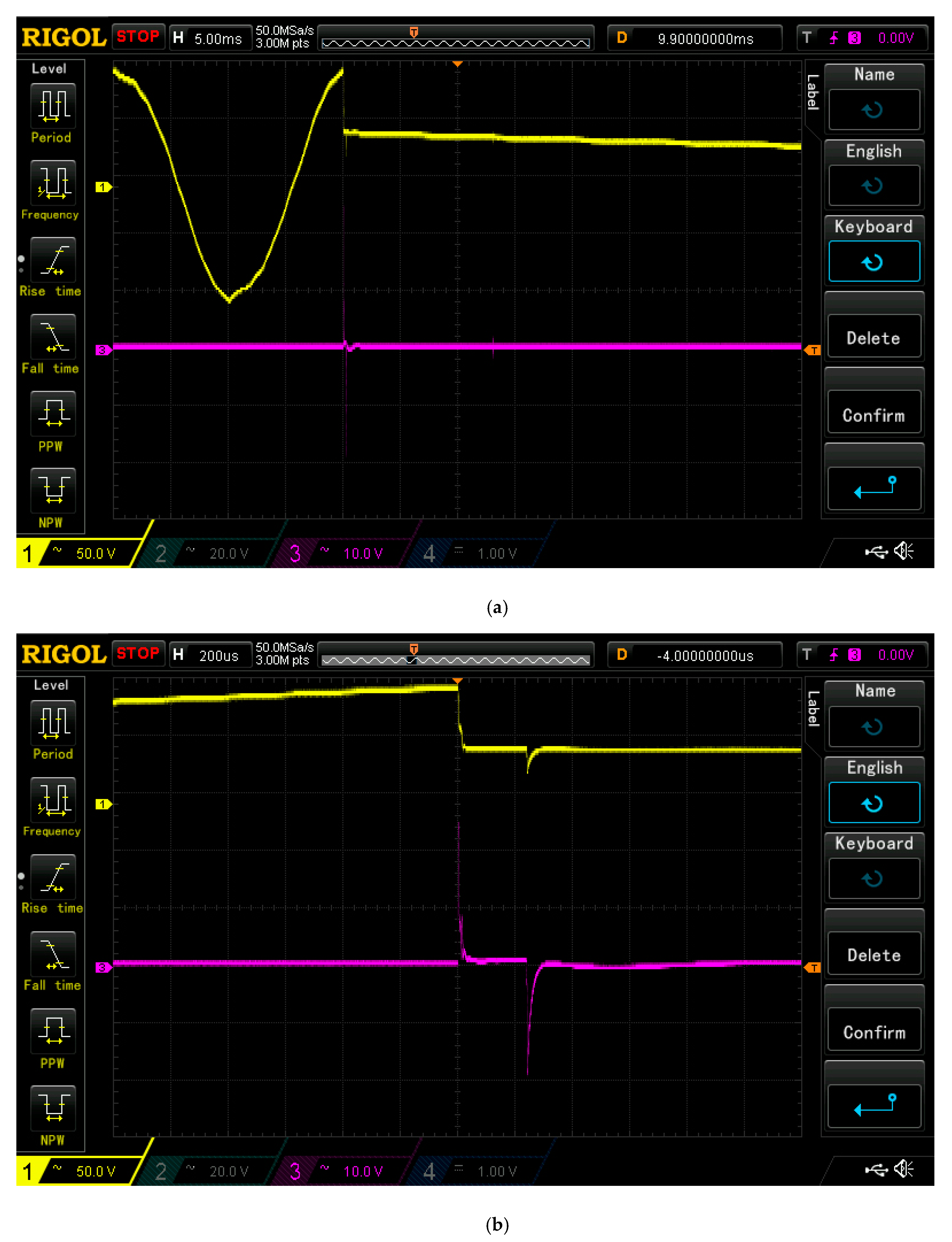
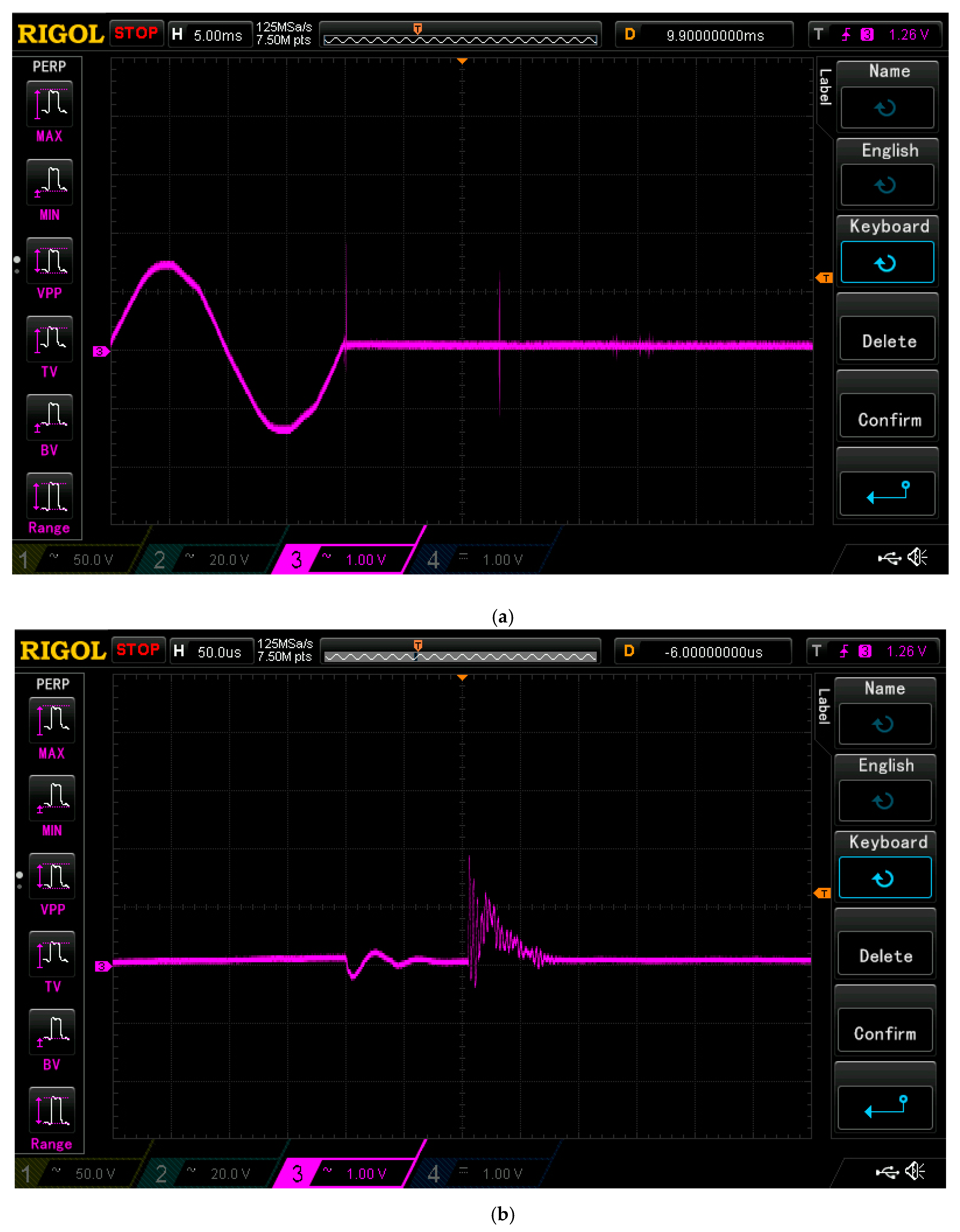
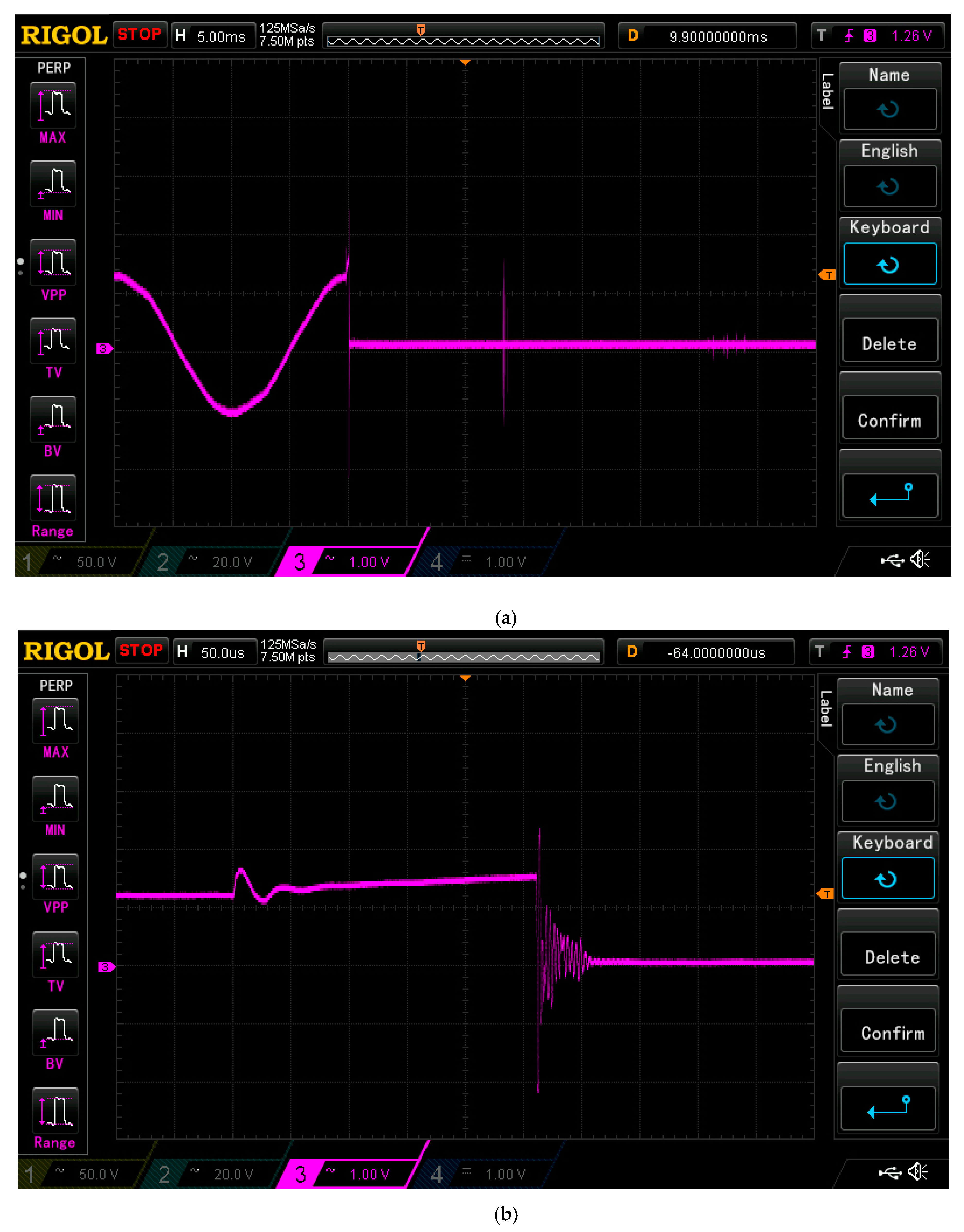
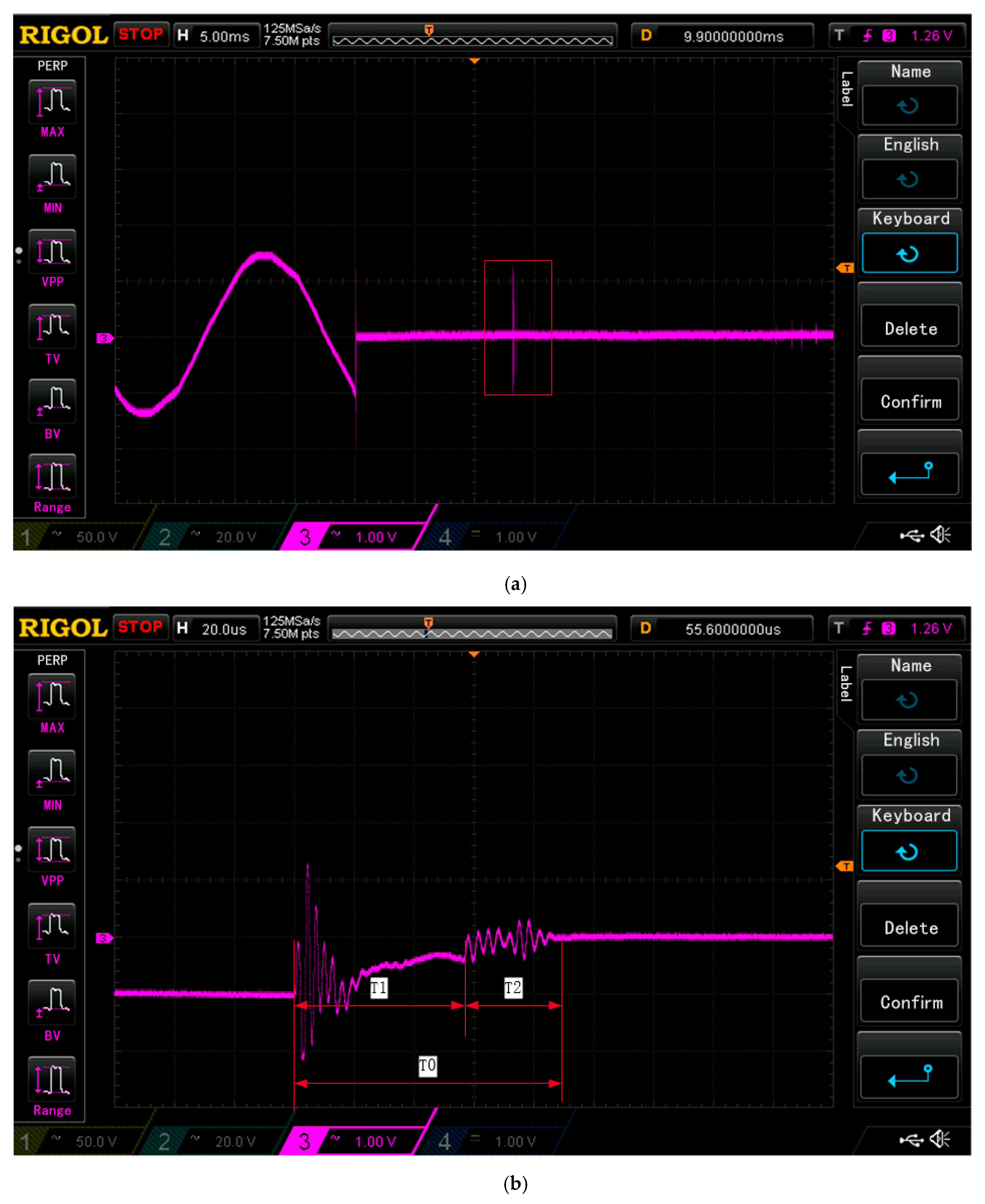
With the above research results, our research group has developed a high-speed interruption switch device based on DSP hardware, and a laboratory experiment has been conducted. The schematic is shown in Figure 4 and Figure 5, where the bus voltage is 660 V, the three-phase symmetrical load current is 10 A, the power factor is 0.95, the single-phase resistance to the ground is 3.5 kΩ, and the single-phase capacitance to the ground is 0.1 μF. In order to demonstrate that such a system is feasible, the following Figure 10, Figure 11, Figure 12, Figure 13, Figure 14 and Figure 15 of the experiment result must be considered:
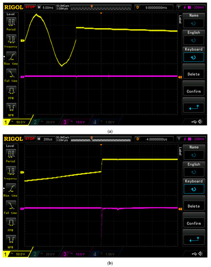
Figure 10.
Figure of fault phase (a) and enlarged view (b) .

Figure 11.
Figure of fault phase (a) and enlarged view (b) .
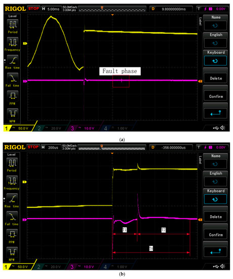
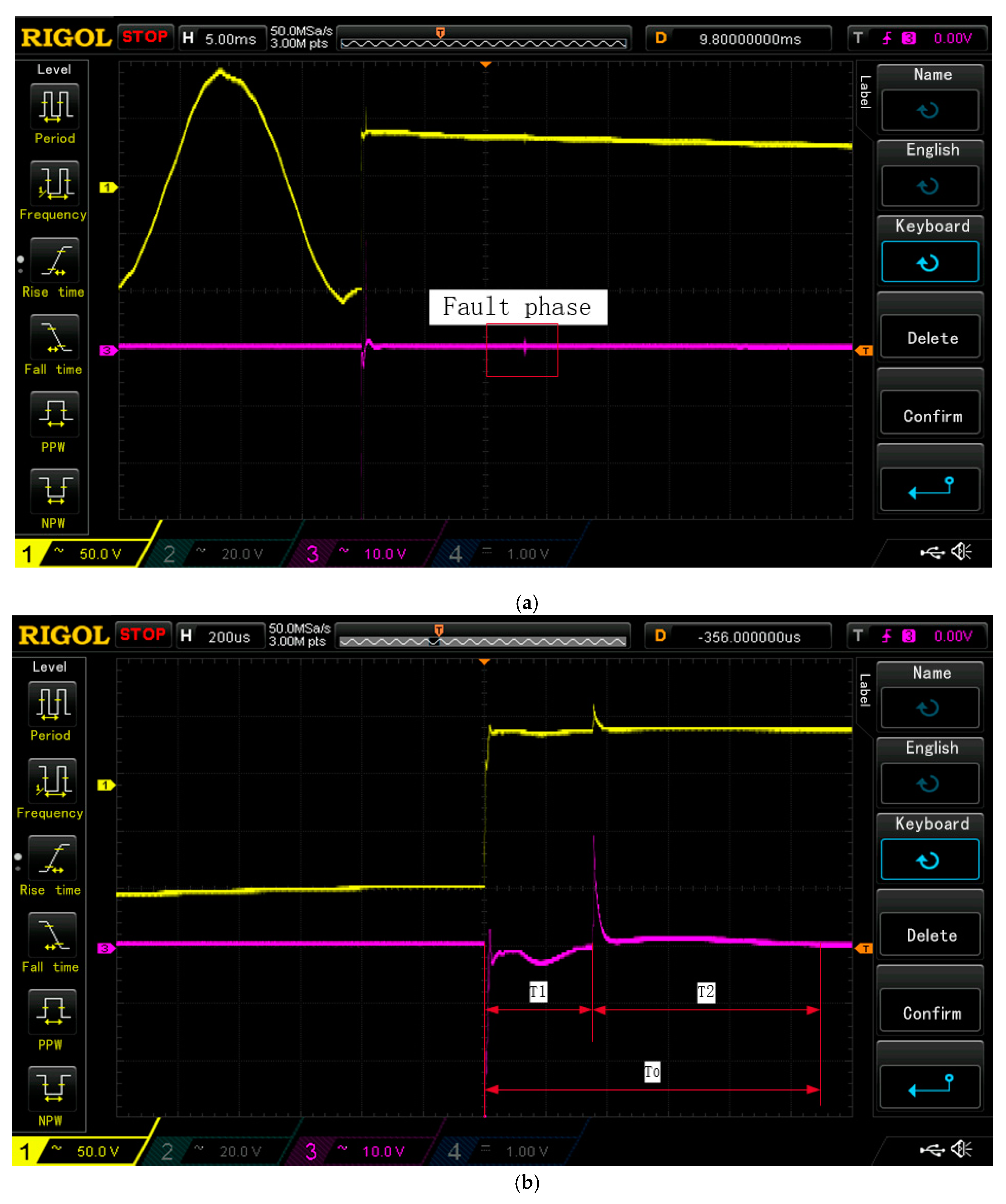
Figure 12.
Figure of fault phase (a) and enlarged view (b) .
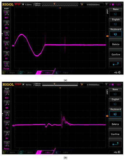
Figure 13.
Figure of fault phase (a) and enlarged view (b) .
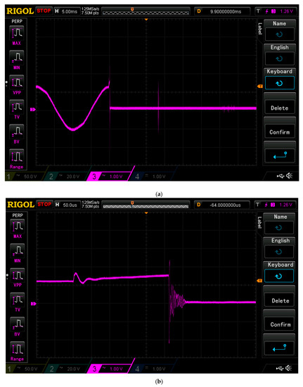
Figure 14.
Figure of fault phase (a) and enlarged view (b) .
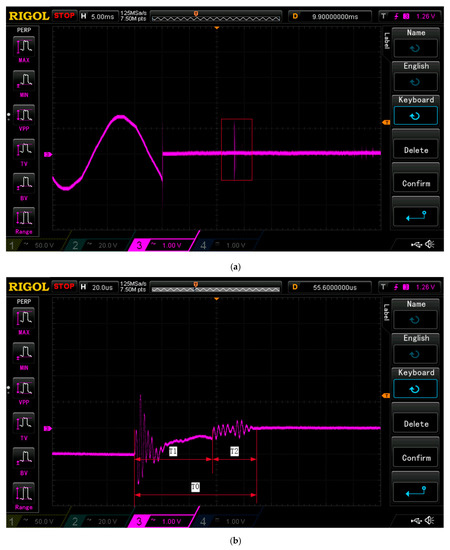
Figure 15.
Figure of fault phase (a) and enlarged view (b) .
In Figure 12, the yellow line is the voltage waveform of fault phase grounding through 10 Ω resistance, the small peak on the purple line is the whole record of the current through the grounding resistance, and the existence time of this wave is also the total power-off time of the single-phase earth leakage fault, which is .
When a three-phase short-circuit fault occurs in cable, the linear current wave form of fault phase is shown in Figure 15, short-circuit current existence time or the total power-off time .
5. Discussion of Results
As underground mining is always at risk from inflammable conditions, the reliability and safety of its power supply system have a high requirement for relay protection. The algorithm of ordinary microcomputer relay protection generally adopts the Fourier algorithm [19], the sampling window is required to be at least half of the industrial frequency time, which is approximately 10 ms, and does not meet the requirements of ultra-high-speed earth leakage protection and short-circuit protection. Meanwhile, the precision of the traditional leakage protection which is based on the steady-state characteristic quantities of the leakage current is not high enough, because the traditional mutual inductor cannot measure precisely due to the change of the single-phase leakage current in consideration of the circuit parameter, transition resistance, stray current and so on [20,21,22]. The method which is based on the half wave of the leakage current has a lot of limits, because the first transient signal is weak during the zero crossing of the phase voltage when the leakage fault occurs, and the weak signal is hard to get [23,24,25].
The ultra-high-speed earth leakage protection algorithm proposed in this paper is based on the transient relay protection algorithm of differential equations. In other words, it is based on establishing the distribution parameter model of each line in the transition process of a single-phase earth leakage fault. The instantaneous values of zero-sequence voltage and zero-sequence current which are collected by synchronous high-speed sets are used as known quantities. The distribution parameters (i.e., insulation resistance and distributed capacitance) of the line to earth are obtained using numerical solutions, the reasonableness of the values (i.e., when both insulation resistance and distributed capacitance are more than zero, it is reasonable) is used as the criterion for fault line selection, and the action time is guaranteed to be less than 2 ms.
For ultra-high-speed short-circuit protection, the common algorithm based on effective values and phases as short-circuit fault criteria should not be used. For example, the methods which are based on the RMS current or the phase sensitivity need more time than the method which is proposed in this paper, because their signal extraction is based on the steady-state current [26,27,28]. The method which is based on the instantaneous value of the short-circuit current is fast enough, but the reliability of this method is low due to its sample mode, which needs the maximal value of the momentary current [29,30,31].
The difference algorithm based on the rate-of-change of the current proposed in this paper, whose actual time is less than 2 ms, should be used. This is in order to prove the action time (2 ms) is maximum at any location in the mining low-voltage power supply system (i.e., length), in any case (i.e., initial phase of failure), and with any fault (i.e., three-phase short-circuit and two-phase short-circuit). In this paper, the rate-of-change of motor starting current, the power factor of starting loop and the phase voltage of the initial phase in start moment are all analyzed and calculated. This will determine the maximum values so that they can then be set as the action settings for ultra-high-speed short-circuit protection. As many people are aware, the minimum short-circuit current of the power supply system is found when a two-phase short circuit fault occurs at the end of the line [32]. In order to ensure that the action of short-circuit protection is reliable, relevant regulations stipulate that the sensitivity factor is greater than 1.5 [33] (i.e., sensitivity factor of short-circuit protection: ratio of short-circuit current to setting). On this basis, the impedance of the short-circuited circuit can be inferred and the rate-of-change of the short-circuit current can be calculated. Theoretical calculation and MATLAB simulation show that the proposed criterion for the rate-of-change of the current of the transient short-circuit protection algorithm ensure that the protection will take false action when the motor powered by the mining flameproof movable substation is in the start process. It will also ensure that the ultra-high-speed short-circuit protection can reliably operate when the two-phase short circuit fault occurs at the end of the line, and the maximum time is no more than 2 ms.
Currently, a vacuum breaker is used as the actuator of relay protection in domestic and foreign situations. A disadvantage of this is that the switch size is large and the inherent action-time is long (the author has measured the inherent action-tie, and its value is not less than 17 ms). The fast-break overcurrent protection time both domestically and abroad is generally set at 100 ms, and the fastest is not less than 40 ms. Therefore, in adding the inherent action-time of the vacuum circuit breaker, the total power-off time is generally not less than 60 ms. In order to meet the requirement that the full off time is less than 5 ms, the inherent action-time of the actuator is required to be no more than 1 ms, so the solid-state breaker SSCB must be selected as the actuator. However, the inherent action-time of the SSCB, which is composed of a typical bidirectional anti-parallel thyristor, is generally 6.67 ms and it cannot meet the requirements of safety technology for high-speed interruption. Therefore, the high-speed solid-state circuit breaker topology at the neutral point of the transformer (SSCB-N), which is composed of IGBT as the main component, is proposed in this paper. The component parameters are designed, prototypes are manufactured, and experimental verification is performed. The results showed that the maximum off time for short-circuit current was less than 1 ms. The results showed that the longest time for SSCB-N was less than 1 ms when the short-circuit current was turned off.
Author Contributions
All authors (Y.G., L.W., Y.W., and S.G.B.) contributed to the preparation of the manuscript. Conceptualization, Y.G.; formal analysis, L.W.; methodology, Y.W.; supervision, Y.W.; project administration, Y.G.; writing—original draft, L.W.; writing—review and editing, S.G.B. All authors have read and agreed to the published version of the manuscript.
Funding
This research received no external funding.
Conflicts of Interest
The authors declare no conflict of interest.
References
- Wang, Y.; Gao, Y. Coal Power Technology; China University of Mining and Technology: Xuzhou, China, 2013. [Google Scholar]
- Tang, Y. Mine Electrical Engineering; China University of Mining and Technology: Beijing, China, 2011. [Google Scholar]
- Wang, Y. Ultra-High-Speed Interruption Safety Technology; Coal Industry Press: Beijing, China, 1996. [Google Scholar]
- Gao, S. Research on the Safe Technology of Rapid Broken-Circuit Protection for 127V Power Pupply System of Mine. Coal Technol. 2001, 20, 14–15. [Google Scholar]
- Ji, L.; Liu, Y.; Chen, D.; Wang, J.; Su, L.; Zhou, X. Status Analysis and Research Progress of the Air-Blast Arc Extinguishing of Low Voltage Circuit Breaker. Smart Grid 2016, 4, 152–156. [Google Scholar]
- Liu, Y. Three Coal Mine Power Supply Protection; Coal Industry Press: Beijing, China, 1999. [Google Scholar]
- HU, T. Mine Grid Leakage Protection; Coal Industry Press: Beijing, China, 1987. [Google Scholar]
- Zou, Y.; Zang, G.; Liu, S. Industrial and Mining Enterprises Leakage Protection Technology; Coal Industry Press: Beijing, China, 2004. [Google Scholar]
- Wang, Y.; Yang, J.; Wang, Y. Application of Solid-State Circuit Breaker in Coal Mine Low -pressure System. Mine Saf. 2012, 43, 110–113. [Google Scholar]
- Zhang, Y. Analysis of Measuring Methods of Grounding Insulation Resistant and Distributed Capacitance of Underground Low-voltage Power Grid. Ind. Mine Autom. 2011, 37, 93–95. [Google Scholar]
- Mou, L.; Meng, Q.; Liu, J. Research on Communication-capable Ground-fault Protection System with Intelligence and Selectivity. J. Electr. Technol. 2003, 18, 82–86. [Google Scholar]
- Wang, Y.W.; Liu, W.J.; Gao, Y.; Wang, N.B.; Qiu, Y.J. New Selective Earth Leakage Protection Scheme Based on Zero-Sequence Current Amplitude and Phase Comparison. J. China Coal Soc. 2010, 35, 515–519. [Google Scholar]
- Wang, Y.W.; Wang, N.B.; Yang, X.Q.; Xing, Q. Selective Leakage Protective System Based on Zero Sequence Power Direction Colliery. Mech. Electr. Technol. 2006, 1, 24–26, 30. [Google Scholar]
- Zhang, C.; Ke, X. Actuality and Development Trend of Leakage Protection for Low-Voltage Mine Electric Network. Colliery Mech. Electr. Technol. 2005, 5, 73–77. [Google Scholar]
- Chen, K.; Chen, S.; Tang, Y. Research on Ground-Fault Protection System for Underground Distribution Networks. Electr. Eng. 2004, 11, 61–64. [Google Scholar]
- Zhao, M. Research of Short Circuit Protection Technology Based on Current Variance Quantity. Power Syst. Technol. 2008, 32, 105–108. [Google Scholar]
- Pang, Y.; Ji, Z. Research of Short Circuit Detecting & Protection Technology Based on Current Variance Ratio. Mine Saf. 2008, 9, 17–20. [Google Scholar]
- HDSP-SUPER2812[ER/OL]. (4 July 2013). Available online: http://www.hellodsp.com/?p=343 (accessed on 10 November 2019).
- Shao, Y. Principles of Relay Protection, 2nd.ed; China Electric Power Press: Beijing, China, 2015. [Google Scholar]
- He, J. The Power System Relay Protection; China Electric Power Press: Beijing, China, 2001. [Google Scholar]
- Wang, L.; Xie, J. Ground Line of the Small Current System by the Rate Change of the Zero Sequence Current Calculating by Simulation. J. Shanghai Univ. Electr. Power 2012, 28, 427–430. [Google Scholar]
- Xue, Y.; Fen, Z.; Xu, B. Earth Fault Protection in Non-Solidly Earthed Network based on Transient Zero Sequence Current Comparison. Autom. Electr. Power Syst. 2003, 27, 48–53. [Google Scholar]
- Chen, K.; Tang, Y. Single-Phase-To-Ground Fault Protection for Indirect Grounding Power System. High Volt. Eng. 2007, 33, 180–184. [Google Scholar]
- Sang, Z.; Pan, Z.; Li, L. A New Approach of Fault Line Identification, Fault Distance Measurement and Fault Location for Single Phase-To-Ground Fault in Small Current Neutral Grounding System. Power Syst. Technol. 1997, 21, 50–52. [Google Scholar]
- Chen, L.; Chen, Q. A Survey on Faulty Line Selection Technology for Single-Phase Grounded Transmission Line in Small Current Neutral Grounded System. Power Syst. Technol. 2009, 18, 219–224. [Google Scholar]
- Liu, J. Analysis and Solutions About Short-Circuit Protection’s Failure of the 127-volt Signal Lighting Integrated under the Coal Mine. J. Beijing Polytech. Coll. 2012, 3, 23–26. [Google Scholar]
- Zhang, L.; Zhang, B.; Yu, H.; Du, L. Research and Development Setting System of Shout Circuit Protection of Mine Low Voltage Network. Technol. Innov. Product. 2013, 1, 70–72. [Google Scholar]
- Chen, K.; Zhang, L.; Sun, C. A New Technology of HV Flameproof Switchgear Comprehensive Protection in Coal Mine. Power Syst. Prot. Control 2009, 37, 137–141. [Google Scholar]
- Chang, X.; Wang, X.; Fang, X. Fundamental Current Instantaneous Value Detection and Synchronized Current Phasor Measurement Method. Power Syst. Prot. Control 2013, 41, 60–66. [Google Scholar]
- Chen, J. A Method of Calculating Electric Capacity Based on Instantaneous Voltage and Instantaneous Current of Two Points. J. Electr. Power 2002, 17, 168–170, 183. [Google Scholar]
- Yang, C. Study on Adaptive Action Criterion of Current Differential Protection Based on Instantaneous Values. Guangdong Electr. Power 2006, 19, 8–13. [Google Scholar]
- Ma, X.; Li, L.; Li, Z.; Han, P. Improvement and Research on the Setting Calculation Method of Overcurret Protection of the Underground High-Voltage Distribution Network of Coal Mine. Power Syst. Prot. Control 2014, 42, 90–95. [Google Scholar]
- The Technical Specification of Setting for Controlling and Protection in HVDC System; State Grid Corporation of China: Beijing, China, 2012; TF; Power Industry Stand of The People’s Republic China: DL/T 277-2012.


© 2020 by the authors. Licensee MDPI, Basel, Switzerland. This article is an open access article distributed under the terms and conditions of the Creative Commons Attribution (CC BY) license (http://creativecommons.org/licenses/by/4.0/).