Article

Optimal Inertia Reserve and Inertia Control Strategy for Wind Farms

1
Wind Power Research Center, School of Electronic Information and Electrical Engineering, Shanghai Jiaotong University, Shanghai 200240, China
2
School of Information Science and Technology, Donghua University, Shanghai 201620, China
*
Author to whom correspondence should be addressed.
Energies 2020, 13(5), 1067; https://doi.org/10.3390/en13051067
Submission received: 21 January 2020 / Revised: 25 February 2020 / Accepted: 25 February 2020 / Published: 1 March 2020
(This article belongs to the Section A3: Wind, Wave and Tidal Energy)

Abstract

:
It is important to reduce the impact of the high penetration of wind power into the electricity supply for the purposes of the security and stability of the power grid. As such, the inertia capability of wind farms has become an observation index. The existing control modes cannot guarantee the wind turbine to respond to the frequency variation of the grid, hence, it may lead to frequency instability as the penetration of wind power gets much higher. For the stability of the power grid, a simple and applicable method is to realize inertia response by controlling wind farms based on a high-speed communication network. Thus, with the consideration of the inertia released by a wind turbine at its different operating points, the inertia control mechanism of a doubly-fed wind turbine is analyzed firstly in this paper. The optimal exit point of inertia control is discussed. Then, an active power control strategy for wind farms is proposed to reserve the maximum inertia under a given power output constraint. Furthermore, turbines in a wind farm are grouped depending on their inertia capabilities, and a wind farm inertia control strategy for reasonable extraction of inertia is then presented. Finally, the effectiveness of the proposed control strategy is verified by simulation on the RT-LAB (11.3.3, OPAL-RT TECHNOLOGIES, Montreal, Quebec, Canada) platform with detailed models of the wind farm.

1. Introduction

With the advance of renewable energy technologies, wind power has developed rapidly in the world. Being different from conventional power plants, there are many new aspects of wind power worth studying, e.g., the wind speed forecasting technology [1,2,3] and the dynamic behavior of wind generators [4]. In recent years, the increasing penetration of wind power into the power system has been gaining much attention [5,6,7], in which the inertia control and primary frequency control of wind turbines are two main aspects. However, a conventional wind turbine cannot independently provide inertia and response frequency variations of the grid, as it needs to update its hardware and software. It is notable that the actions of wind power on a power system occur usually in a form of a wind farm. For wind farms, adding a frequency-detecting loop on a control station and installing a high-speed communication system may be a more feasible method of inertia and frequency control. This is the reason to study inertia control methods from the view of the wind farm.
In the wind farm, the automatic generation control (AGC) can be used to optimize active output reference of a wind turbine according to power dispatch constraints from the superior control center and the wind speed. Inertia control of the wind farm can be carried out based on fast instruction distribution of the AGC system. For a wind turbine, an active power control instruction has its inertia reserve, which may not be equal to each other. Many investigations have been done on active control strategies, such as active power instruction equalization control [8], instruction distribution with the optimum target of reducing the number of wind turbine starts and stops [9] and clustering control based on wind turbine power trend [10]. These studies all take tracking grid dispatching instructions as an active control objective of the wind farm and do not consider the system frequency regulation and inertia response; [8,9,10,11,12] proposed an principle of active power control in the wind farm based on generation plan tracking and supplemented by system frequency regulation, but its discussion seems quite simple.
In the study of wind turbine inertia control [5,13,14], a frequency control loop is added to the conventional wind turbine and the electromagnetic torque of the unit is quickly adjusted when the system frequency changes. Through adjusting the active power output, the increase or decrease of the kinetic energy of the rotor can be controlled, and thereby the isolated inertia of the wind turbine can be extracted to realize the damping effect on the frequency variation. In [15], an estimation method is provided for the gain of the active power controller of a turbine for inertial control, but the control limits were not discussed. Releasing inertia of a wind turbine will reduce its rotational speed. This means that the available inertia of a wind turbine is restricted by its minimum speed. In order to avoid turbine stall, the studies mentioned above actually set the minimum rotation speed of the wind turbine as the exit point of the inertia control. However, these papers did not discuss the exit point of the inertia control of a wind turbine and the recovery process after the system disturbance. The authors of [16] compared three new inertial control strategies of a wind turbine, i.e., proportional and differential control, virtual synchronous generator (VSG) control and inertial synchronization control (ISynC). They pointed out that VSG control and ISynC can improve the stability of a turbine operated under weak grid condition and that the VSG strategy can reduce frequency secondary drop. In [17], the inertia control gain was presented to protect the wind turbine from stalling and a coordinated control involving the rotor speed control was then applied to decrease the system frequency deviation. The authors of [18] deduced the inertia control exit point of wind turbine to minimize the secondary drop of frequency. It should be pointed out that, in the above discussion, the input power of the wind turbine was assumed to be constant during the change of the rotation speed. However, wind energy captured by a wind turbine will also be changed with the change of rotation speed, so it has to affect the inertia capability of a wind turbine. On the other hand, for wind farms, it is necessary to avoid the secondary drop of the system frequency caused by a large number of wind turbines simultaneously entering the recovery state as soon as the inertia control is finished [19]. In other words, wind turbines should recover in order. This can follow the order from the lower speed wind turbines to prevent the speed protection being triggered and tripping. In [20], the influence of the dynamic recovery process of the wind turbines on the system frequency stability was studied in the case of the setting a recovery delay for each wind turbine. However, the difference of the operating state of the wind turbine was not considered. Numerous researchers have focused on the inertial responses at the wind turbine level, whereas few efforts have been devoted to the wind farm level [21]. A probabilistic approach to estimating the aggregated inertial response from a wind farm was proposed in [22], but the inertial control was not taken into account. A wind farm inertia control was presented in [23], where a long-term dynamic simulation was performed in a further step. Generally speaking, a simple, reliable and effective wind farm inertia control technology remains to be further studied.
To solve the problems mentioned above, an inertia control process of the doubly-fed wind turbine (DFIG) is analyzed firstly in this paper. The wind turbine inertia control exit point which considers the input wind energy variation resulting from rotor speed decrease is also discussed. Following that, a wind farm active power control strategy with maximized inertia reserve is proposed. This control strategy can improve the overall reserve inertia of the wind farms while tracking the reference from superior power grid control center. On this basis, a phased wind farm inertia control strategy is proposed to improve the stability and safety of wind farm inertia support in the case of sudden changes in grid frequency.

2. Active Power and Inertia Control Principle of Doubly-Fed Induction Generator

2.1. Power Control of DFIG

Figure 1 shows the relationship between rotating speed ( ω ) and active power ( P ). During steady-state operation, a wind turbine operates under (maximum power point tracking (MPPT)) control mode, or it can reduce output power according to active power reference from superior control center. In the most used MPPT mode, wind turbines will operate under the preset optimal power curve (Popt in Figure 1). In deloaded operation, a wind turbine will deviate from maximum power operation point on MPPT curve by regulating rotational speed or pitch angle, such as operating on Pdeloaded in Figure 1.
Acceleration control (such as point B) and deceleration control (such as point C) both can reduce output power of a wind turbine. However, acceleration control is more practical since deceleration control has stability problems. Thus, PoptPdeloaded can be considered as the active power reserve.
Active power reserve can also be obtained through pitch control. Figure 2 shows the relationship between pitch angle ( β ) and power coefficient ( C p ). When increasing pitch angle, from point B to point A in Figure 2, the wind turbine will capture less wind energy. Conversely, the wind turbine rotor will capture more wind energy with the decrease of pitch angle.
Wind turbine active power regulation by speed control is suitable for operating conditions below rated wind speed. It is also suitable for inertia control, since the power regulation is realized by converter and can be adjusted quickly, rather than pitch control which is realized by servo motor. Consequently, pitch control fails to participate in fast frequency regulation but can be used as a supplement to speed control since it has a wider range of adjustable active power. In this paper, speed control is used for active power regulation.

2.2. Inertia Control of DFIG

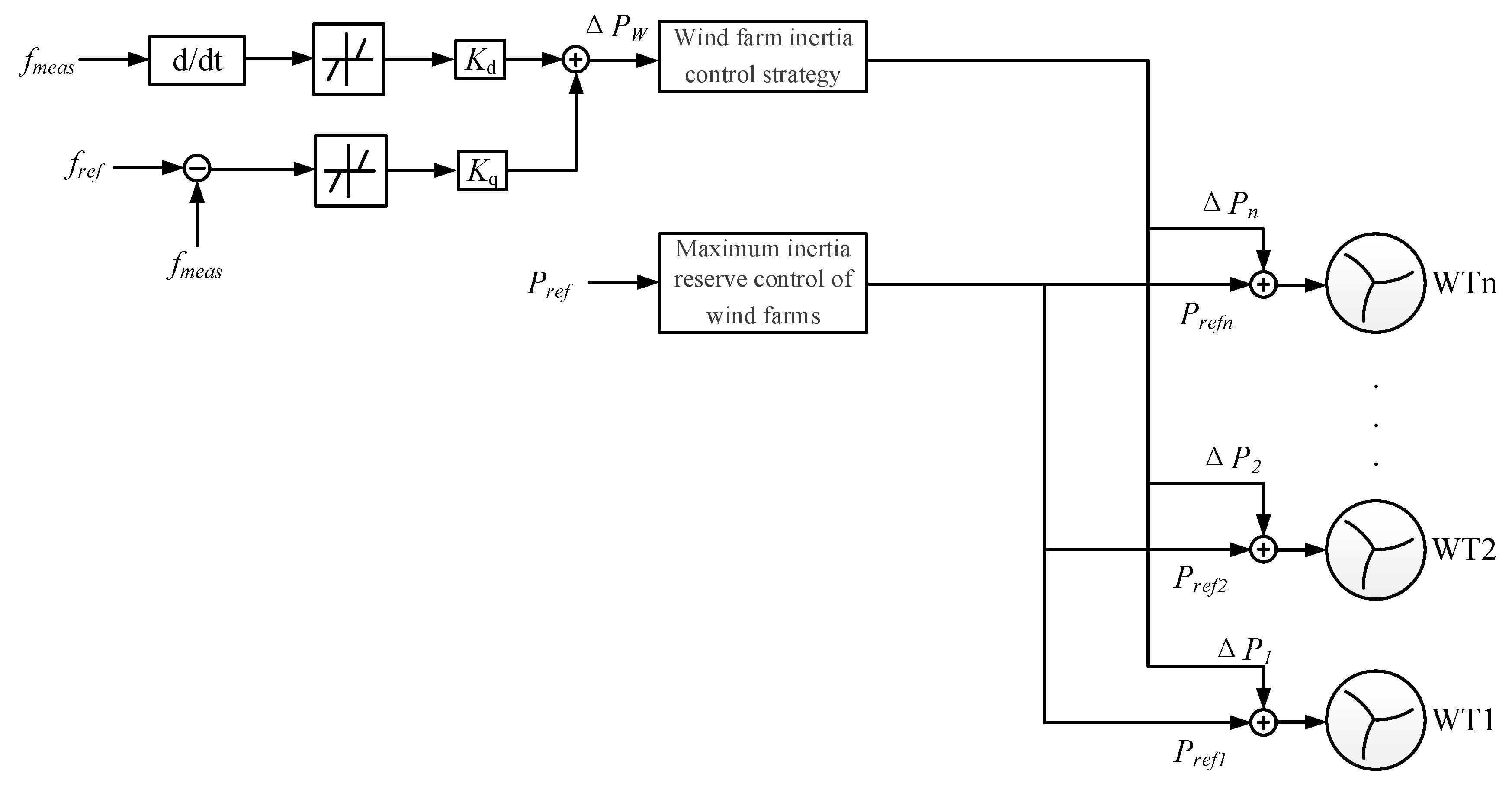
Under the conventional control strategy, DFIG will not provide any inertia for the grid in transient state. However, the inertia control can be realized by applying a frequency control loop in the control system. At present, the most commonly used method [9,10,11] is to introduce a proportional and differential control (PD control) of system frequency deviation into the basis of conventional control of wind turbine. Thus, DFIG can simulate the inertial control of a synchronous generator when the system frequency varies abruptly. The method only needs to add additional active power to the original given power instruction of the main controller to reflect the frequency fluctuation. The convertor will implement power conversion according to the original control strategy. In this way, kinetic energy of the turbine is released or absorbed through rotation speed change and then the system frequency variations are damped. Figure 3 shows the structure of PD control in which f m e a s is the frequency actually measured, f r e f is the frequency reference and k p and k d are the proportional coefficient and integration coefficient, respectively.
When system frequency drops, the kinetic energy of the generator rotor will be released. This will lead to a rotational speed drop and further influence wind energy capture of wind turbine rotor because of the characteristic between the rotor speed and the torque. Thus, the inertia available also reduces. Hence, it is necessary to analyze the exit point of inertia control for the optimal behavior of wind turbine in transient state.

3. Analysis of the Exit Point of the Inertia Control of a Wind Turbine

To prevent the wind turbine from stalling during inertia control, the generator rotor speed has an allowable upper and lower limit constraint. Therefore, it is critical to focus on the exit point of the wind turbine participating in the frequency response.
During the process of inertia control, the increased output power of the wind turbine by the release of rotational kinetic energy can be expressed as:
Δ P R     =       d ( 1 2 J ω 2 ) d t
where J is the sum of generator inertia and wind turbine rotor inertia (reduction to generator rotor side) and ω is the rotational speed of generator rotor.
However, with the acceleration or deceleration of wind turbine rotor during inertia control, the wind energy which the wind turbine captures from wind will vary since the power coefficient C p is a variable of rotational speed. If the wind turbine operates in reduced power mode before system frequency drops, deceleration will lead to an increase of wind energy captured. Thus, the controllable electromagnetic power for wind turbine increases, which is beneficial for system frequency recovery. On the contrary, if the wind turbine is in MPPT mode before system frequency drops, deceleration will lead to a decrease of wind energy capture. This part of the wind energy loss will also be reflected in the transient output power, and it will weaken the inertia control effect. Hence, it is necessary to discuss the quantitative relationship between the wind energy captured and the rotational kinetic energy released. The change of wind power captured due to the speed variation can be expressed as:
d P turb d t = P wind d ( C p ( λ , β ) ) d t
where P wind is the wind energy on the surface of wind turbine rotor, C p ( λ , β ) is the rotor power coefficient, λ is the tip speed ratio and β is the pitch angle. Since the inertia response time constant of wind turbines is generally in second order, it can be considered that the wind speed is constant in this process; that is, P wind can be considered as a constant.
In the process of inertia control, the extra output power of wind turbine can be expressed as:
d P wt d t       =       d P R d t       +       d P turb d t
Obviously, it is necessary to keep d P turb d t       >       0 during inertia control and the wind turbine must exit inertia control when d P turb d t       =       0 , as shown in Figure 4.
The exit point of inertia control is:
d ( 1 2 J ω 2 ) d t       +     P wind d ( C p ( λ , β ) ) d t       =       0
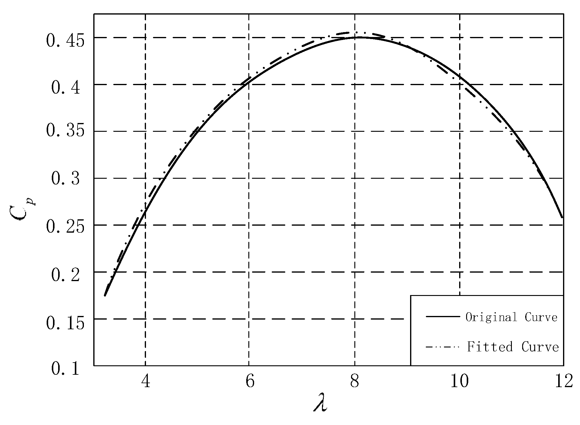
Since pitch control is relatively slow, pitch angle can be considered constant during inertia control. So, it can be considered as a function of the rotor speed of a generator ω with fixed pitch angle β . In general, taking β       =     0 as an example, C p ( λ ) can be shown as Figure 5.
The approximate relationship of λ and C p can be obtained by binomial fitting with real data, as follows:
C p =   0.01195 λ 2 + 0.1911 λ 0.3126 =   0.01195 ( R w ω V wind ) 2 + 0.1911 ( R w ω V wind ) 0.3126
where R w is the radius of wind turbine rotor and V wind is the wind speed.
Combining Equations (4) and (5), we have:
ω = 0.1911 R w P wind J V wind 0.0239 R w P wind
The rotating speed in Equation (6) is the exit point of inertia control of a wind turbine. This shows that the exit point is relative to initial wind speed.
Similarly, in other operation points with different pitch angles, the exit point can be derived with the relationship between C p ( λ ) and ω . Wind turbine manufacturers can calculate the inertia control exit point table offline and download it to main controller program. Thus, a wind turbine can be controlled online to exit inertia control according to the querying table.

4. Maximum Inertia Reserve Control of Wind Farms

A wind power base in China has the capacity of millions of kilowatts. The active power control in such a big wind power base is usually hierarchical. Normally, there are three hierarchies, as shown in Figure 6. The first hierarchy is the provincial dispatching who will calculate optimal power flow and gives active power references to 330 kV regional substations. The second hierarchy is the regional active power control, who will give the optimal power references to wind farms. The third hierarchy is wind farm active power control, who will give the optimal power references to wind turbines. Each hierarchy dispatches active power optimally according to the superior instructions.
As can be seen from the above discussion, the distribution of active power control instructions in wind farms will determine the available inertia of wind turbines. Therefore, if the wind farms operate in the state of maximum inertia reserve before faults occur in the power system, it will provide a better support in transient for the grid. Thus, maximum inertia reservation is used as one of the optimization targets in this paper.
Taking the random volatility of wind power into account, the active power reference from superior control center is always determined by wind farm power prediction with a certain margin. Therefore, it is generally smaller than the sum of every wind turbine MPPT value. Thus, it leaves room for wind farm inertia control. That is to say, the allocation of a wind turbine’s power is not uniquely meant to satisfy the requirement of active power reference for whole wind farms. Based on high speed communication system, a wind farm active power control strategy which can realize both wind farm active power reference tracking and wind farm inertia reverse maximization is presented and shown in Figure 7. A real-time frequency control loop is added to wind farm AGC. It can trigger wind farm inertia control when system frequency drops to a preset threshold value. Thus, the inertia in each wind turbine can be extracted to damp frequency variation.

4.1. Mathematical Model of Steady-State Wind Farm Active Power Control

The objective of wind farm active power control is to minimize the error between output of wind farm and the power reference from the superior control center. Then, the objective function can be written as:
f 1 = P W F · r e f i = 1 n P i r e f
where P W F r e f is the active power reference from superior control center, P i r e f is the power reference of the i th wind turbine in wind farms and n is the number of wind turbines.
A wind turbine in deloaded operation can realize decrease power output by increasing the rotor speed. In this way, the wind turbine will have a certain amount of inertia from the viewpoint of the grid. The wind farm can coordinate the operation point of each wind turbine, and therefore it has the ability of maximizing its inertia reserve. So, it is the focus of discussion to establish a method to optimize the wind turbine power reduction operation point in the wind farm.
The kinetic energy in wind turbine is calculated as follows:
E k       =       1 2 J ω 2
Equation (8) shows that the inertia of wind turbine is relative to its rotating speed. Therefore, the inertia reserve objective function is:
f 2 = 1 2 J i = 1 n ( ω i 2 ω i min 2 )
where ω i is the rotating speed of the i th wind turbine after using inertia control and ω i min is the exit point of the i th wind turbine.
By combining the above two optimization objective functions, a multiobjective optimization mathematical model for wind farm active power control can be established:
F = min ( α f 1 + β 1 f 2 )
where α and β are the weight coefficients of the two objects.
Constrained conditions are:
P i min P i r e f P i max
i = 1 n P i r e f P WF r e f
ω i min ω i ω i max
where P i min and P i max are the lower limit and upper limit of the i th wind turbine, respectively, and ω i max is the upper limit of the i th wind turbine rotating speed.

4.2. Solving Algorithms

In this paper, the proposed multiobjective optimization problem is solved by genetic algorithm. Its purpose is to find a set of active power references [ P 1 , P 2 , , P n ] for wind turbines to minimize multiobjective functions.
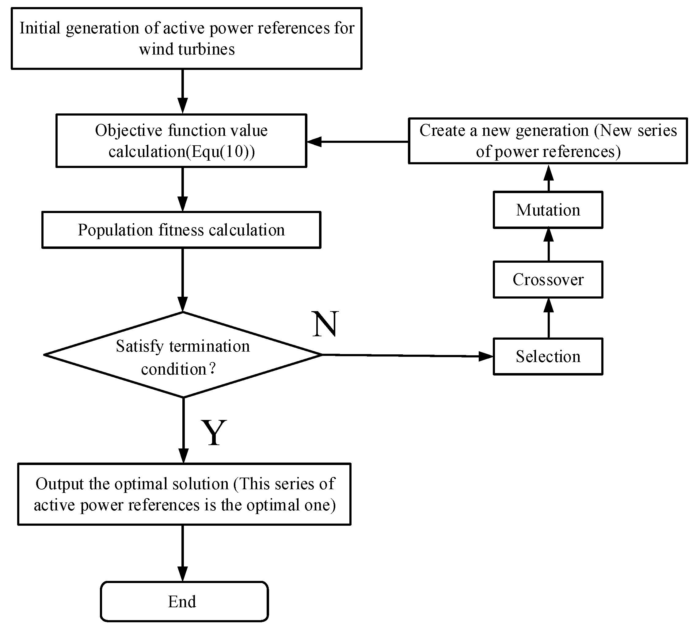
The solution flow chart is shown in Figure 8.
(1)
The genetic algorithm first randomly generates n individuals within the constraint range. Each individual which represents the initial active reference sequence is encoded by a string of binary codes. Thus, the first objective function f 1 (Equation (7)) is obtained. With the deloaded control relationship between rotating speed and active power, the rotating speed individuals can be derived. Thus, the second objective function f 1 (Equation (9)) is obtained.
(2)
Combine f 1 and f 2 , the multiobjective optimization mathematical function F is obtained. The multiobjective function value can be calculated under the active reference sequence and take the result as a fitness function.
(3)
The calculation is made in per-unit value, and the termination condition is F 0.01 . If the fitness calculation result does not satisfy the termination condition, the program will select the individuals which lead to a better fitness and keep them for the next sequence.
(4)
To make the fitness calculation result better, the crossover and mutation operations in the genetic algorithm are performed, and then new individuals, which stand for the new generation of active power references sequence, are derived constantly. The crossover refers to the operation of replacing the partial binary code of two previous individuals to generate new individuals. The excellent traits of the parent chromosome are inherited to the next generation chromosome to the greatest extent, and some better traits can also be produced during this period. The mutation refers to the operation of changing one binary code of previous individuals at random to generate new individuals.
(5)
Using the fitness function to evaluate the fitness of each generation repeatedly will result in a set of individuals with the strongest fitness through continuous evolution. Finally, this set of individuals is the solution of the model.

5. Wind Farm Inertia Control Strategy

The purpose of wind farm inertia control is to prevent frequency variance by regulating active power of wind farms quickly. The inertia provided by the wind farm is released by wind turbines which are controlled coordinately by the AGC in the wind farm substation.
The control network in a conventional wind farm adopts TCP/IP communication protocol whose control period is usually from 6 to 15 s. However, if the wind farm would participate in the frequency regulation of the power system, it is necessary to apply a fast communication technology like the EtherCAT bus to shorten the control cycle to 100 milliseconds.
The characteristics of frequency compensation of a wind farm depend on the control parameters of inertia control. From the point of view of analog synchronous generator, the wind farm control parameters k d and k q can be based on the principle that a wind farm can provide the same inertia as a conventional power plant has capacity.
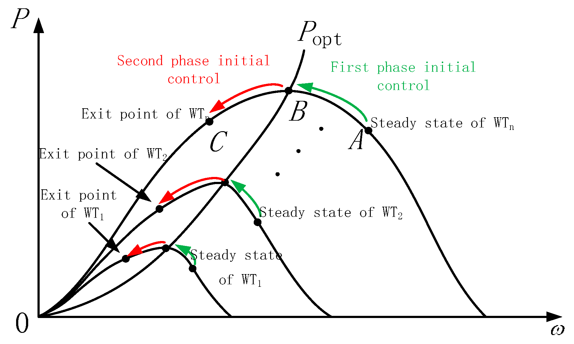
The wind turbines in a wind farm can be divided into two categories according to their operating status: deloaded operating state and MPPT operating state. In the first category, the wind turbines operate in deloaded operating state by accelerating. In this state, the process of inertia release can be further divided into two phases. The first phase is the process of rotating speed dropping to the MPPT point and the second phase is the process of rotating speed dropping from the MPPT point to the inertia control exit point. Obviously, the wind turbines in second category will only go through the second phase. According to the conclusion of Section 2.2, the kinetic energy released by wind turbine is the sum of the variation of kinetic energy of the generator rotor and the variation of the absorbed wind energy caused by the change of the rotating speed of the wind turbine rotor. During the first phase, as the rotating speed decreases, the wind turbine operating point is close to the MPPT point, so the wind energy absorbed by the wind turbine rotor increases. Therefore, the amount of change in the kinetic energy of the generator rotor and the change in the amount of absorbed wind energy due to the deceleration are positive. During the second phase, the inertia control effect is weaker than that in the first phase since the wind energy absorbed by the wind turbine rotor is reduced continuously. Considering the above characteristics synthetically, a phased coordinated inertia control strategy of wind farms is proposed. As shown in Figure 9, firstly, the AGC of a wind farm controls the wind turbines in deloaded operation to release their inertia (Point A to Point B in Figure 9). If the first phase is completed and the system still needs inertia support, the wind farm AGC will start the second phase of inertia control (Point B to Point C in Figure 9). In the second phase, wind farm AGC will control all wind turbines to release their inertia until their rotating speeds drop to exit points.
Since a wind turbine with different rotating speeds has different inertia control potentials, it is useful to define the inertia support capability indicator for coordinated control. In the first phase, the inertia support capability indicator is defined as:
ρ 1 = ( ω i 2 ω MPPT 2 ) i = 1 m ( ω i 2 ω MPPT 2 )
where m is the number of wind turbines participating in first phase inertia control, that is, the wind turbines in deloaded operation. ω MPPT is the optimal speed of a wind turbine under the current wind speed. Thus, the change of active power reference of the i th wind turbine participating in the inertia control during the first phase is:
Δ P i = ρ 1 Δ P W
In the second phase, the inertia support capability indicator of the i th wind turbine is defined as:
ρ 2 = ( ω i 2 ω i min 2 ) i = 1 n ( ω i 2 ω i min 2 )
where n is the number of wind turbines participating in second phase inertia control which equals that of nonfault wind turbines in the wind farms. ω i min is the exit point of the i th wind turbine. The change of active power reference of the i th wind turbine in the second phase can be written as:
Δ P i = ρ 2 Δ P W

6. Case Study

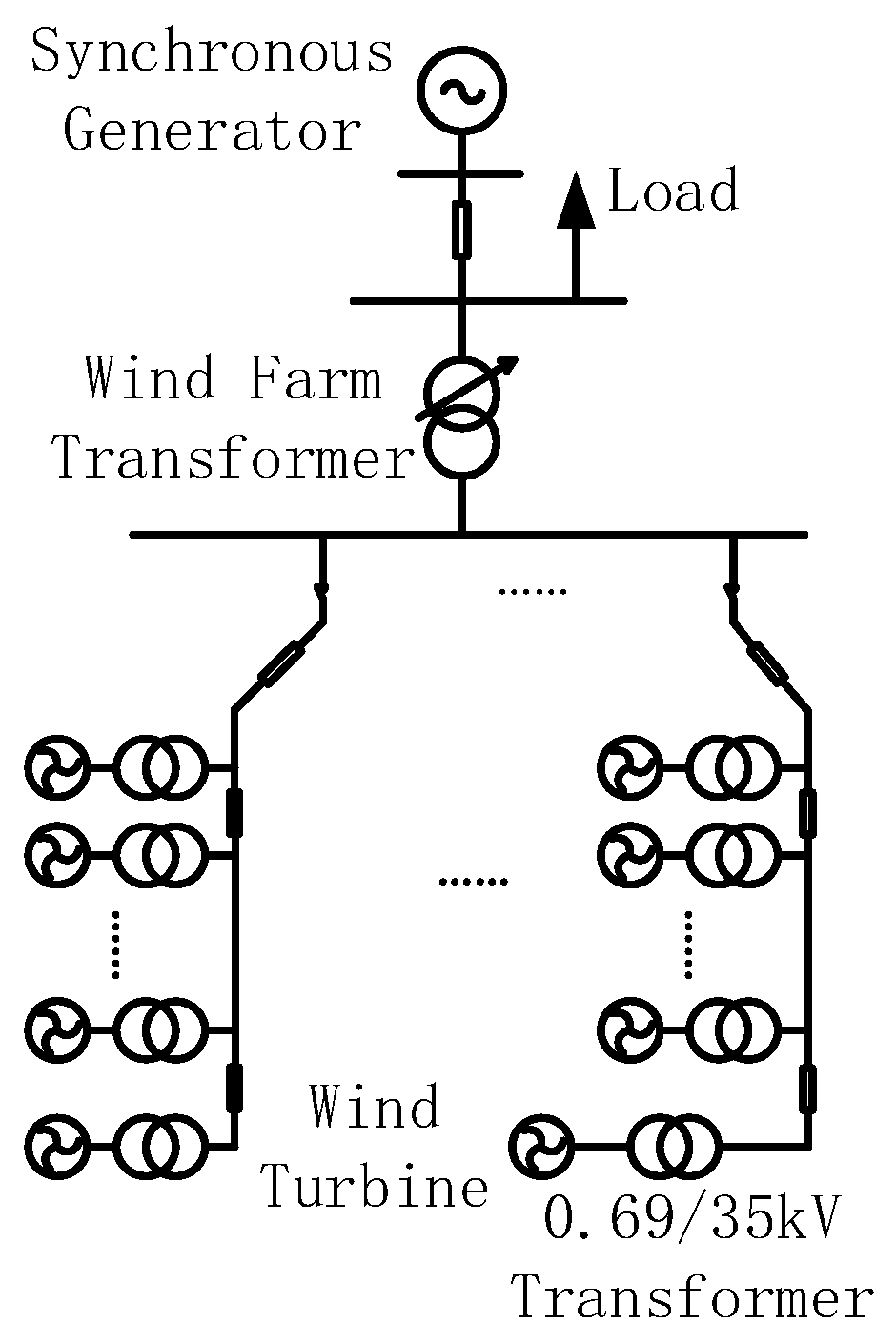
To verify the proposed control strategy, a 100 MW wind farm model was built in RT-LAB simulation platform referring to the actual structure of large-scale wind farms in China. The wind farm is equipped with 50 DFIGs with the capacity of 2 MW. The rated wind speed is 11.8 m/s, and the inertia of all rotating parts is 684 kg·m2 (reduction to generator rotor side). The wind farm has five feeders, and each feeder is equipped with 10 DFIGs. The length of the line between each DFIG is 0.4 km; its resistance is 0.17 Ω/km, and its reactance is 0.402 Ω/km. The wind farm voltage is boosted by a transformer with the capacity of 100 MVA and the ratio of 110 kV/35 kV. It is connected to the external grid via a 100-km-long line whose resistance is 0.132 Ω/km and reactance is 0.357 Ω/km. The rated capacity of the synchronous generator is 500 MW, and its generator frequency coefficient is 0.05. The topology of the wind farm is shown in Figure 10.

6.1. Verification of Inertia Reserve of Proposed Control Strategy

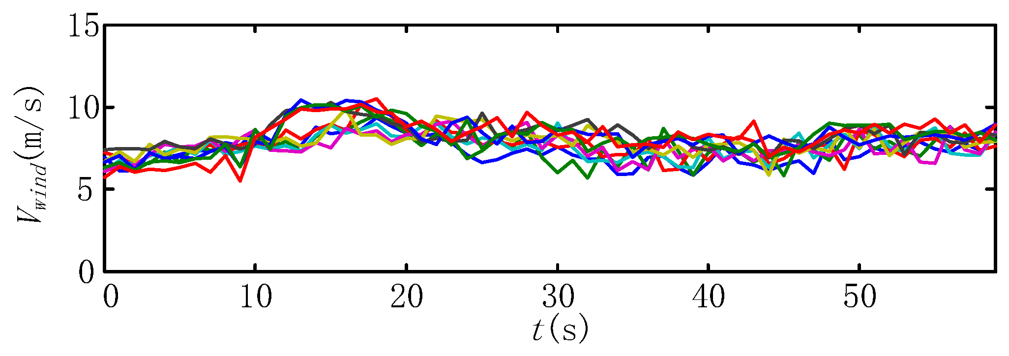
The effect of proposed coordinated control strategy is verified by using second-order wind speed data of a real wind farm as input. In the simulation, time cycle of control of wind farm AGC is set to 6 s, and the simulation time is 1 min. Figure 11 shows the wind speed curves of 10 wind turbines on a feeder in the wind farms. The effect of the control strategy proposed in this paper is compared with that of the conventional capacity allocation algorithm and the maximum power allocation algorithm [23,24] by simulation. In the simulation, the reference from the superior control center is increased from 40 to 50 MW at 30 s. The reference tracking ability under the three control strategies is shown in Figure 12, and their corresponding inertia reserves of the wind farms (EW) are shown in Figure 13.
It can be seen from the simulation results that all three control strategies can track the reference from the superior control center precisely and punctually, but the wind farm inertia reserve has obvious differences. Besides, compared with the conventional wind farm inertia control strategies, the control strategy proposed in this paper has significantly improved the wind farm inertia reserve.

6.2. Inertia Control Verification of Wind Farms

In the case study, wind speed distribution of a real wind farm at a certain moment is taken, and the average is 9.7 m/s. Among wind turbines, 15 operated in deloaded operation, and the rest operated in the MPPT. The active power reference of the wind farm is 55 MW. A conventional synchronous generator model with 500 MW rated power is used as an equivalent grid. The load is 300 MW and is increased by 5 MW or 40 MW at t = 2 s. The simulation results of the proposed inertia control strategy for a wind farm are compared with those of the wind farm without inertia control and those of the strategy proposed by [25] where the inertia control of wind farm is based on frequency control capability of wind turbines.

6.2.1. Evaluation Index System

1. Evaluation index of damping capability to frequency plunge in grid
Damping capability to grid frequency plunge is one of the main indicators to evaluate the effect of wind farm inertia control. It can be described by the most relative deviation of the grid frequency, shown as Equation (18), as follows:
δ f _ damp = Δ f max f B × 100 %
where Δfmax stands for maximum deviation of grid frequency and fB is the rated frequency of the grid, which is 50 Hz.
2. Evaluation index of grid frequency secondary drop
As mentioned above, there is a reasonable exit point for the inertia control of the wind turbine. Usually, it is necessary to exit the inertia control mode when the wind turbine reaches the preset lower limit of the speed so as to ensure that the generator speed is always in a reasonable range. However, after wind turbine exits its inertia control, the process of speed recovering often causes a secondary drop in the grid frequency. δ 2 _ B is defined as an evaluation index of the frequency deviation of the secondary frequency drop relative to the rated frequency in the grid in this paper. It indicates the degree of secondary frequency drop in the grid under different inertia control.
δ 2 _ B = Δ f 2 _ max f B × 100 %

6.2.2. Simulation Analysis

1. Control effect after increasing load by 5 MW
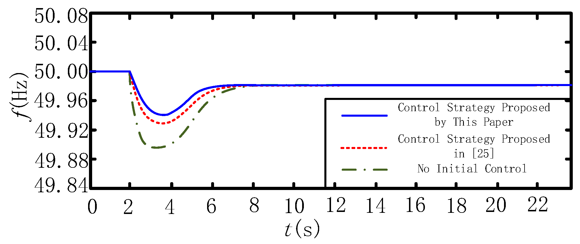
The simulation results are shown in Figure 14 and Figure 15 when system load increases by 5 MW from 300 MW at t = 2 s.
It can be seen from the simulation results that the wind farm with inertia control can provide active power support to the system and damps frequency changes when the system frequency drops. Compared with the control strategy proposed in [25] ( δ f _ damp       =       0.14 % ), the control strategy proposed in this paper ( δ f _ damp       =       0.102 % ) results in a better damping effect on frequency variation. The reason for this is that the proposed control strategy in this paper adjusts the deloaded operation wind turbines preferentially. Thus, the power output increased relatively faster, and the energy released during the same period is greater.
2. Control effect after increasing load by 40 MW
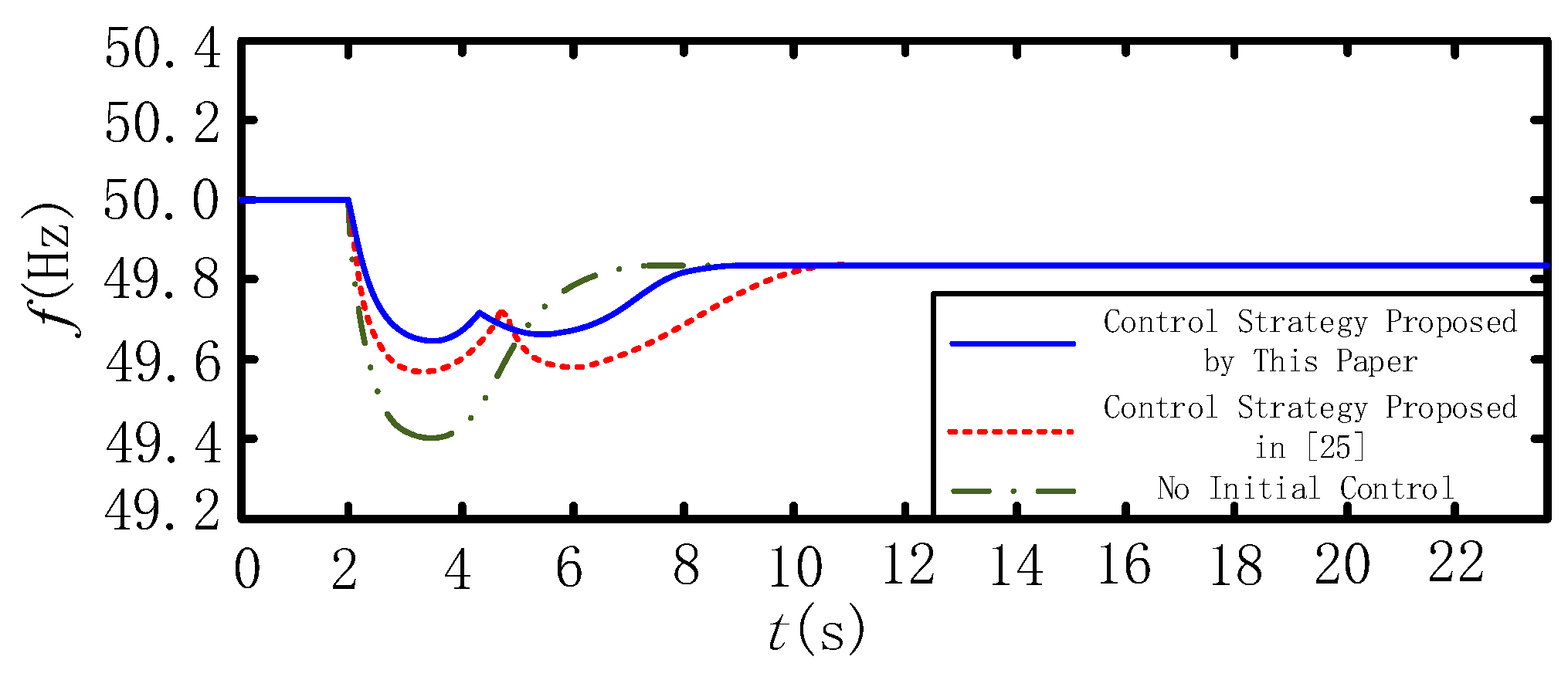
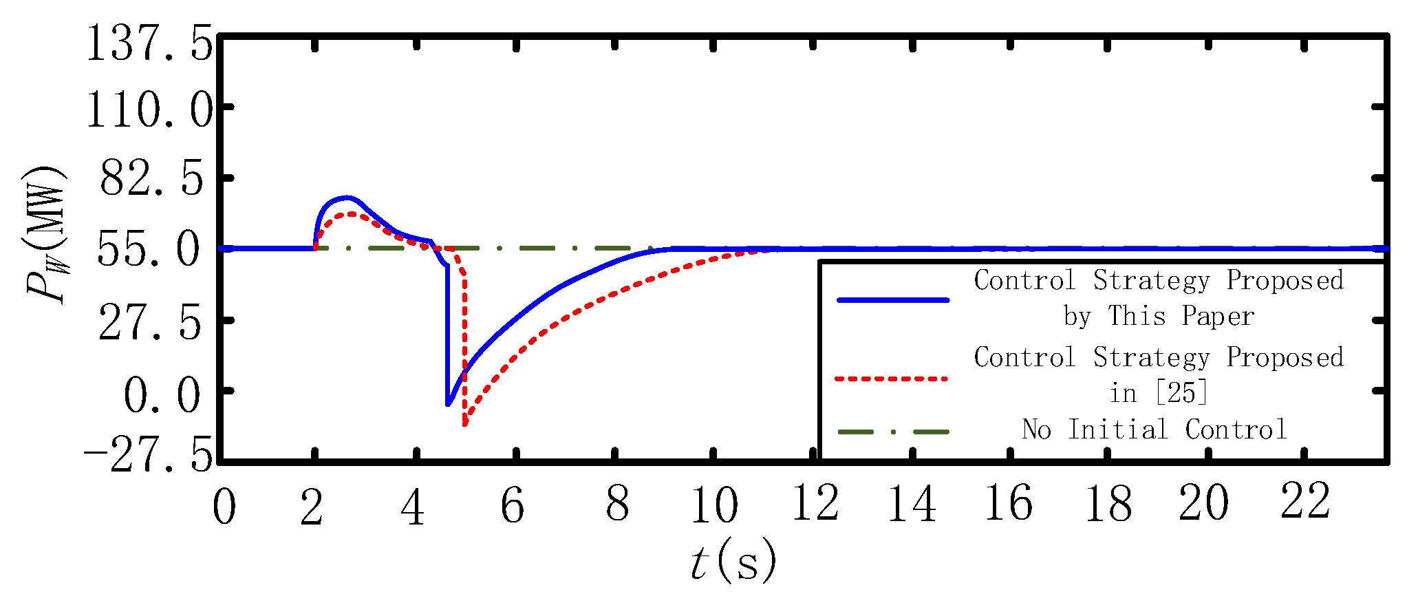
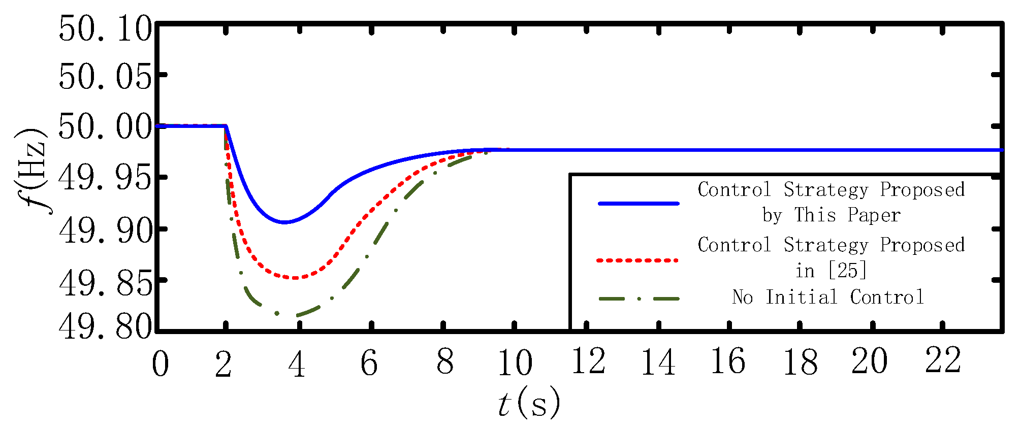
The simulation results are shown in Figure 16 and Figure 17 when system load increases by 40 MW from 300 MW at t = 2 s.
It can be seen from Figure 16 and Figure 17 that, due to the large load variation, the system frequency changes rapidly and the wind farm with inertia control releases its inertia as much as possible to damp frequency change, until the wind turbines reach their exit points. After exiting the inertia control, the active power delivered to the system by wind turbines is reduced in order to recover the rotating speeds. This will result in a second drop in the system frequency. The control strategy proposed in [25].
Only takes the minimum speed of the wind turbine as the inertia control exit point ( δ f _ damp       =       0.84 % , δ 2 _ B       =       0.84 % ). Compared with the control strategy proposed in this paper, the exit speed is lower, the secondary frequency drop is greater and frequency recovery takes longer ( δ f _ damp       =       0.69 % , δ 2 _ B       =       0.72 % ).
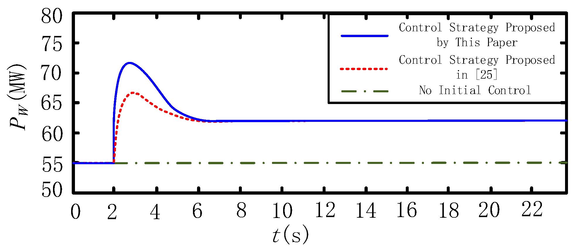
3. Control effect when load is increased by 5 MW (synchronous generator’s frequency coefficient decreases to 0.02)
In the above simulations, the synchronous generator’s frequency coefficient is 0.05, which is the typical value of a thermal generator. With the increasing proportion of wind power, the frequency adjustment of the synchronous generator will be weakened because its relative capacity is reduced. This means that the synchronous generator will provide smaller inertia under the same frequency variance. The increasing penetration of wind power can be simulated by reducing the synchronous generator’s frequency coefficient. In simulation 3, the synchronous generator’s frequency coefficient is decreased to 0.02. The remaining simulation conditions are the same as those of simulation 1.
From the Figure 18 and Figure 19, the frequency drop is greater than the result in simulation 1. The reason for this is that the synchronous generator produces less active power when frequency decreases since its frequency coefficient decreases. In this situation, δ f _ damp of the proposed control strategy is 0.16% while δ f _ damp of the control strategy proposed in [25] is 0.28%. Obviously, the wind farm with the proposed control strategy provides greater damping when frequency fluctuates. In conclusion, the proposed control strategy will contribute to an increase of system inertia and a decrease of frequency fluctuation with the high penetration of wind power.

7. Conclusions

For the inertia control of wind turbine, most studies focused on the control of wind turbine inertia release and lacked discussion on the exit point of wind turbine inertia control and the recovery process after the system disturbance. In this paper, the mechanism of the inertia control of a DFIG was firstly analyzed. According to the relationship between the kinetic energy released by the rotor and the captured wind energy caused by the change of rotational speed, the reasonable exit point of the inertia control was derived, which is related to the initial rotational speed of a wind turbine.
Actually, it is practical to realize inertia response through controlling a wind farm at present. Based on the above discussions, a wind farm steady-state active power control strategy with maximum inertia reserve was proposed. This strategy can realize an optimal wind farm inertia reserve while satisfying the active power dispatching instructions from a superior control center.
Finally, based on the operating points of wind turbines, a novel wind farm inertia control strategy was proposed, which enables the wind turbines in the wind farm to release the inertia coordinately. Compared with a conventional control strategy, it can significantly reduce the system frequency drop and reduce the secondary frequency drop as well.
It is worth noting that the conclusions derived are not only applicable to DFIG wind farms but are also applicable to wind farms with other types of wind turbines as long as they are equipped with a high-speed communication system. Since the most popular grid-connected wind turbines are equipped with power convertors, such as direct drive wind turbines, they can realize inertia release through convertor control. On the other hand, vertical axis wind turbine [26] has a different wind energy capture characteristic than a horizonal axis wind turbine, but its power coefficient is also related to rotating speed. Thus, the inertia control exit point can be derived by the relationship between rotating speed and wind energy captured.

Author Contributions

Conceptualization, Y.C. and Z.L.; methodology, Y.C.; software, Y.C.; validation, Y.C.; formal analysis, Y.C. and Z.L.; investigation, Z.L.; resources, Y.C.; data curation, Y.C.; writing—original draft preparation, Y.C. and Z.L.; writing—review and editing, Z.L. and X.C.; visualization, Y.C.; supervision, X.C.; project administration, X.C.; funding acquisition, X.C. All authors have read and agreed to the published version of the manuscript.

Funding

This research was funded by National Natural Science Foundation of China, grant number 51677117.

Acknowledgments

The authors are grateful to professor Zhengzhi Han for reviewing the manuscript.

Conflicts of Interest

The authors declare no conflict of interest.

References

  1. Fu, T.; Wang, C. A Hybrid Wind Speed Forecasting Method and Wind Energy Resource Analysis Based on a Swarm Intelligence Optimization Algorithm and an Artificial Intelligence Model. Sustainability 2018, 10, 3913. [Google Scholar] [CrossRef] [Green Version]
  2. Ganea, D.; Mereuta, E.; Rusu, E. An Evaluation of the Wind and Wave Dynamics along the European Coasts. J. Mar. Sci. Eng. 2019, 7, 43. [Google Scholar] [CrossRef] [Green Version]
  3. Wang, L.; Liu, J.; Qian, F. Frequency Distribution Model of Wind Speed Based on the Exponential Polynomial for Wind Farms. Sustainability 2019, 11, 665. [Google Scholar] [CrossRef] [Green Version]
  4. Wang, B.; Tang, Z.; Gao, X.; Liu, W.; Chen, X. Distributed Control Strategy of the Leader-Follower for Offshore Wind Farms under Fault Conditions. Sustainability 2019, 11, 2290. [Google Scholar] [CrossRef] [Green Version]
  5. Vidyanandan, K.V.; Senroy, N. Primary frequency regulation by deloaded wind turbines using variable droop. IEEE Trans. Power Syst. 2013, 28, 837–846. [Google Scholar] [CrossRef]
  6. RogÉrio, G.; de Almeida, J.A.; Lopes, P. Participation of doubly fed induction wind turbines in system frequency regulation. IEEE Trans. Power Syst. 2007, 22, 944–950. [Google Scholar] [CrossRef] [Green Version]
  7. Fu, Y.; Wang, Y.; Zhang, X. Integrated wind turbine controller with virtual inertia and primary frequency responses for grid dynamic frequency support. IET Renew. Power Gener. 2017, 11, 1129–1137. [Google Scholar] [CrossRef]
  8. Fernandez, L.M.; Garcia, C.A.; Jurado, F. Comparative study on the performance of control systems for doubly fed induction generator (DFIG) wind turbines operating with power regulation. Energy 2008, 33, 1438–1452. [Google Scholar] [CrossRef]
  9. Moyano, C.F.; Peças Lopes, J.C. An optimization approach for wind turbine commitment and dispatch in a wind park. Electr. Power Syst. Res. 2009, 79, 71–79. [Google Scholar] [CrossRef] [Green Version]
  10. Guo, Y.; Wang, W.; Tang, C.Y.; Jiang, J.N.; Ramakumar, R.G. Model predictive and adaptive wind farm power control. In Proceedings of the IEEE 2013 American Control Conference, Washington, DC, USA, 17–19 June 2013; pp. 2890–2897. [Google Scholar] [CrossRef]
  11. Zhao, H.; Wu, Q.; Huang, S.; Shahidehpour, M.; Guo, Q.; Sun, H. Fatigue load sensitivity based optimal active power dispatch for wind farms. IEEE Trans. Sustain. Energy 2017, 8, 1247–1259. [Google Scholar] [CrossRef] [Green Version]
  12. Gao, Z.; Teng, X.; Zhang, X. Solution of Active Power Dispatch and Control Scheme for Interconnected Power Grids with Large-scale Wind Power Integration. Autom. Electr. Power Syst. 2010, 34, 37–41. [Google Scholar] [CrossRef] [Green Version]
  13. Gautam, D.; Goel, L.; Ayyanar, R.; Vittal, V.; Harbour, T. Control strategy to mitigate the impact of reduced inertia due to doubly fed induction generators on large power systems. IEEE Trans. Power Syst. 2011, 26, 214–224. [Google Scholar] [CrossRef]
  14. Morren, J.; de Haan, S.W.H.; Kling, W.L.; Ferreira, J.A. Wind turbines emulating inertia and supporting primary frequency control. IEEE Trans. Power Syst. 2006, 21, 433–434. [Google Scholar] [CrossRef]
  15. Ma, H.; Chowdhury, B. Working towards frequency regulation with wind plants: Combined control approaches. IET Renew. Power Gener. 2010, 4, 308–316. [Google Scholar] [CrossRef]
  16. Zhang, Z.S.; Sun, Y.Z.; Lin, J.; Li, G.-J. Coordinated frequency regulation by doubly fed induction generator-based wind power plants. IET Renew. Power Gener. 2012, 6, 38–47. [Google Scholar] [CrossRef]
  17. Liu, Z.; Ding, L.; Wang, K. Control strategy to mitigate secondary frequency dips for DFIG with virtual inertial control. In Proceedings of the IEEE China International Conference on Electricity Distribution, Xi’an, China, 10–12 October 2016; pp. 1–5. [Google Scholar] [CrossRef]
  18. Motamed, B.; Chen, P.; Persson, M. Comparison of primary frequency support methods for wind turbines. In Proceedings of the 2013 IEEE, PowerTech (POWERTECH), Grenoble, France, 16–20 June 2013. [Google Scholar] [CrossRef]
  19. James, C.F.; Rick, W. Frequency response capability of full converter wind turbine generators in comparison to conventional generation. IEEE Trans. Power Syst. 2008, 23, 649–656. [Google Scholar] [CrossRef]
  20. Sun, Y.; Zhang, Z.; Li, G.; Lin, J. Review on frequency control of power systems with wind power penetration. In Proceedings of the 2010 IEEE International Conference on Power System Technology (POWERCON), Hangzhou, China, 24–28 October 2010; pp. 1–8. [Google Scholar] [CrossRef]
  21. Lin, W.; Wen, J.; Liang, J.; Cheng, S.; Yao, M.; Li, N. Towards an assessment of power system frequency support from wind plant-modeling aggregate inertial response. IEEE Trans. Power Syst. 2013, 28, 2283–2291. [Google Scholar]
  22. Francois, B. High wind power penetration in isolated power systems-assessment of wind inertial and primary frequency responses. IEEE Trans. Power Syst. 2013, 28, 2412–2420. [Google Scholar] [CrossRef]
  23. Rodriguez-amendo, J.L.; Arnalte, S.; Burgos, J.C. Automatic generation control of a wind farm with variable speed wind turbines. IEEE Trans. Energy Convers. 2007, 17, 279–284. [Google Scholar] [CrossRef]
  24. Yao, X.; Su, X.; Tian, L. Wind turbine control strategy at lower wind velocity based on neural network PID control. In Proceedings of the 2009 IEEE International Workshop on Intelligent Systems and Applications, ISA2009, Wuhan, China, 23–24 May 2009; pp. 1–5. [Google Scholar] [CrossRef]
  25. Chen, Y.; Wang, G.; Shi, Q.; Fu, L.; Jiang, W.; Huang, H. A new coordinated virtual inertia control strategy for wind farms. Autom. Electr. Power Syst. 2015, 39, 27–33. [Google Scholar] [CrossRef]
  26. Sun, X.; Zhu, J.; Hanif, A.; Li, Z.; Sun, G. Effects of blade shape and its corresponding moment of inertia on self-starting and power extraction performance of the novel bowl-shaped floating straight-bladed vertical axis wind turbine. Sustain. Energy Technol. Assess. 2020, 38. [Google Scholar] [CrossRef]
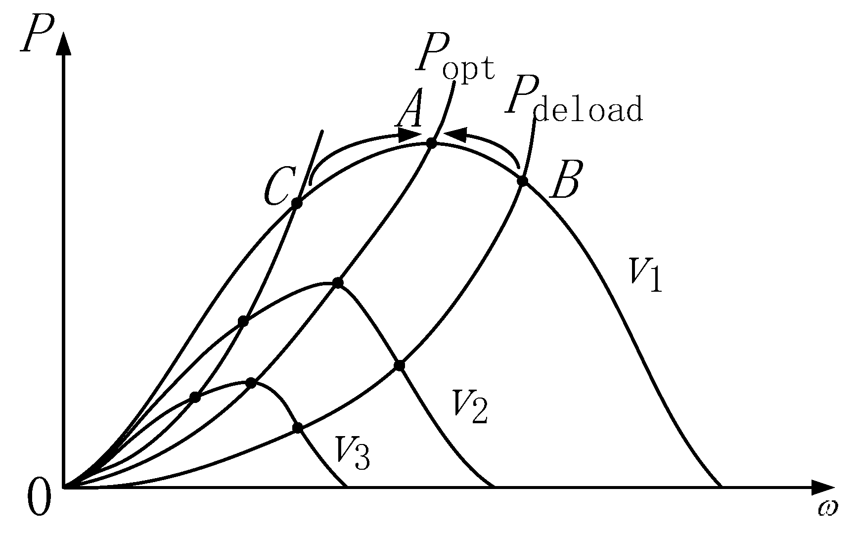
Figure 1. Schematic diagram of deloaded operation by speed control.
Energies 13 01067 g001
Figure 2. Schematic diagram of deloaded operation by pitch control.
Energies 13 01067 g002
Figure 3. Proportional and differential (PD) control of a doubly-fed wind turbine (DFIG).
Energies 13 01067 g003
Figure 4. Power changes during inertia control.
Energies 13 01067 g004
Figure 5. Curve of rotor power coefficient and tip speed ratio.
Energies 13 01067 g005
Figure 6. Hierarchical active power control in Chinese wind base.
Energies 13 01067 g006
Figure 7. Wind farm active power control system frame.
Energies 13 01067 g007
Figure 8. Genetic algorithm solution process flow.
Energies 13 01067 g008
Figure 9. Phased coordinated wind farm inertia control strategy.
Energies 13 01067 g009
Figure 10. Topology of the wind farm model.
Energies 13 01067 g010
Figure 11. Wind speed curve of 10 wind turbines on a feeder.
Energies 13 01067 g011
Figure 12. Active power of wind farms at PCC (Point of Common Coupling).
Energies 13 01067 g012
Figure 13. Wind farm inertia reverses.
Energies 13 01067 g013
Figure 14. System frequency when load increases by 5 MW.
Energies 13 01067 g014
Figure 15. Wind farm active power when load increases by 5 MW.
Energies 13 01067 g015
Figure 16. System frequency when load increases by 40 MW.
Energies 13 01067 g016
Figure 17. Wind farm active power when load increases by 40 MW.
Energies 13 01067 g017
Figure 18. System frequency when load increases by 5 MW (generator frequency coefficient 0.02).
Energies 13 01067 g018
Figure 19. Wind farm active power when load increases by 5 MW (generator frequency coefficient 0.02).
Energies 13 01067 g019