1. Introduction
Hydrogen is considered one of the most attractive sustainable energy carriers available to cope with global warming and depletion of fossil fuels, thanks to its ability to store and deliver usable energy [
1]. It has to considered that the gas storage volume is almost 1000 times larger than the electricity storage volume in analyzed countries [
2], and that the annual demand for hydrogen is expected to increase ten-fold by 2050—from 8 exajoule (EJ) in 2015 to almost 80 EJ in 2050 [
3]. Hydrogen is crucial in power-to-X applications, such as electricity conversion, energy storage, and reconversion pathways that exploit surplus electric power, mainly during periods where fluctuating renewable energy generation exceeds load [
4,
5,
6,
7,
8].
Hydrogen can be produced from various processes, such as natural gas reforming, coal and biomass gasification, or water electrolysis. Water electrolysis is considered the most attractive and promising solution when renewable energy sources (RES) are used to generate electricity to supply an electrolyzer (EL). The operation of ELs is based on the water electrolysis principle, where de-ionized water is split into hydrogen and oxygen by using electricity from RES [
9].
Different EL technologies can be differentiated based on their electrolyte and charge carriers, such as alkaline ELs, proton exchange membrane (PEM) ELs (PEM-ELs), and solid oxide (SO) ELs (SO-ELs) [
9]. Alkaline and PEM technologies are currently commercially available on the market, unlike SO technology, which is still in the research and development phase. On one hand, alkaline ELs are currently the most mature and widespread technology, while PEM technology is still under development. On the other hand, PEM technology exhibits several advantages over alkaline technology, such as high current densities, good compromise in terms of power-to-weight ratio, faster response to dynamic operations, wider current range, and high flexibility in operation [
10]. Therefore, this technology is particularly fit for insertion into grids, including renewable energy generation systems. This is the reason why a PEM-EL was considered to carry out this work.
The integration of RES into hydrogen production systems results in new design constraints on ELs. These are mainly related to electronic power systems used to supply and control the hydrogen production systems, the performance of ELs, and the electrical requirements involved in the integration. The aim is the improvement of the energy efficiency of the complete system [
11]. In this scenario, both the efficiency of the power conversion system and the EL must be investigated, including the effects of generated harmonics, which lead to additional heat losses in the water electrolysis process [
12]. In the past, hydrogen production has been based on large current rectifiers [
13], of which two main categories can be recognized: thyristor-based rectifiers with hybrid filters (TRHF) and diode rectifiers with multiphase IGBT-based choppers (CRPF). The large rectifier approach exploits the power available from the grid to supply a high-current EL [
14,
15]. Nowadays, the spreading of distributed power generation together with the availability of low-power PEM-EL, along with new converter topologies, have partially modified this approach. Indeed, the power available from RES can be lower or higher than the rated power of an EL, requiring the management of loads [
16,
17] or hybrid combinations of two or more renewable power generation systems in stand-alone or grid-connected configuration, with the storage being based on a hydrogen carrier [
18]. For instance, the need for suitable modeling and a management system is assessed in [
19], whereas in [
20] the issues related to the intermittency of wind generation are investigated. On the other hand, it is possible to obtain high conversion efficiency with the use of an array of converters and PEM-ELs [
21]. In a survey focused on multistack and modular fuel cells [
22], an array configuration (i.e., parallel architecture, in which each fuel cell is connected to the DC bus through a power converter) presents several advantages, such as having better reliability (i.e., in the case of a faulty converter) and flexibility from a control point of view. In this work, each power converter can be controlled according to the available power from the wind turbine conversion system (WTCS). As a result, the energy efficiency of the system can be enhanced, since the Faraday efficiency improves by increasing the current density [
23,
24].
Since the DC–DC converters are important components for PEM-ELs, a stacked interleaved DC–DC buck converter (SIBC) has been chosen to carry out this work. Based on previous work [
25], it offers better reliability and power density. Additionally, the output current ripple can be canceled regardless of the operation of the converter due to the use of an additional capacitor (located between the two main phases), while the control of the two power switches is performed in the opposite way. The minimization or cancellation of the output current ripple is one of the main features expected to optimize the efficiency of the PEM-EL [
26]. Even if the literature for PEM-ELs [
12,
26,
27,
28] does not show papers in which the reduction of the hydrogen production is evaluated, all ELs exhibit an impedance-versus-frequency curve that diminishes by increasing the frequency. This means that voltage harmonics superimposed onto the DC component result in a low current, which in turn causes poor hydrogen production due to the degradation of the Faraday efficiency. For this reason, it would be preferable to supply an EL with a pure DC source; unfortunately, this is often unfeasible due to the need for power conversion. The amount of power loss into the harmonics depends on the impedance curve, the measurement methods for which are stated in [
29].
This article proposes an array architecture based on a SIBC in parallel configuration, allowing the operation of several converters, depending on the available power. This number is chosen so that each converter always operates at its maximum efficiency. The parallel architecture is particularly suitable when exploiting RES, where the available power is subjected to variations over time. The design of SIBC takes into account the dynamic model of the PEM-EL and the model of the wind generator. This converter is fit to face the high voltage of the RES, with a reduced voltage ripple supplying the EL. The remaining power surplus can be used for energy storage devices (e.g., batteries).
This article is divided into seven sections. After this introduction, which provides the current state-of-the-art and reasons for carrying out this work,
Section 2 introduces the system under study and highlights the main feature required for the DC–DC converter. Then, in
Section 3, the specifications, modeling, and characterization of the studied wind turbine are given. In
Section 4, the studied PEM-EL is presented, along with its model. In
Section 5, details are provided regarding the SIBC and the system specifications. In
Section 6, the developed power management strategy is introduced. Finally, in
Section 7, the experimental test bench is presented and experimental results are provided to validate the performance of the developed power management strategy.
2. Wind Turbine Conversion System Coupled with Multistack PEM Electrolyzers
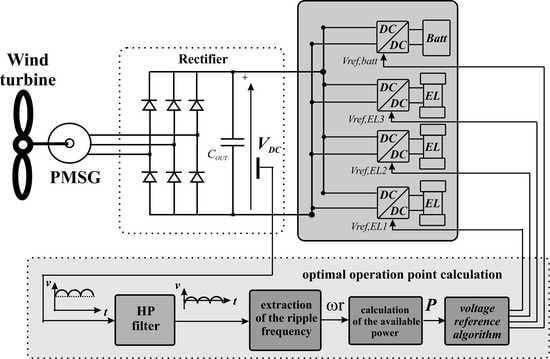
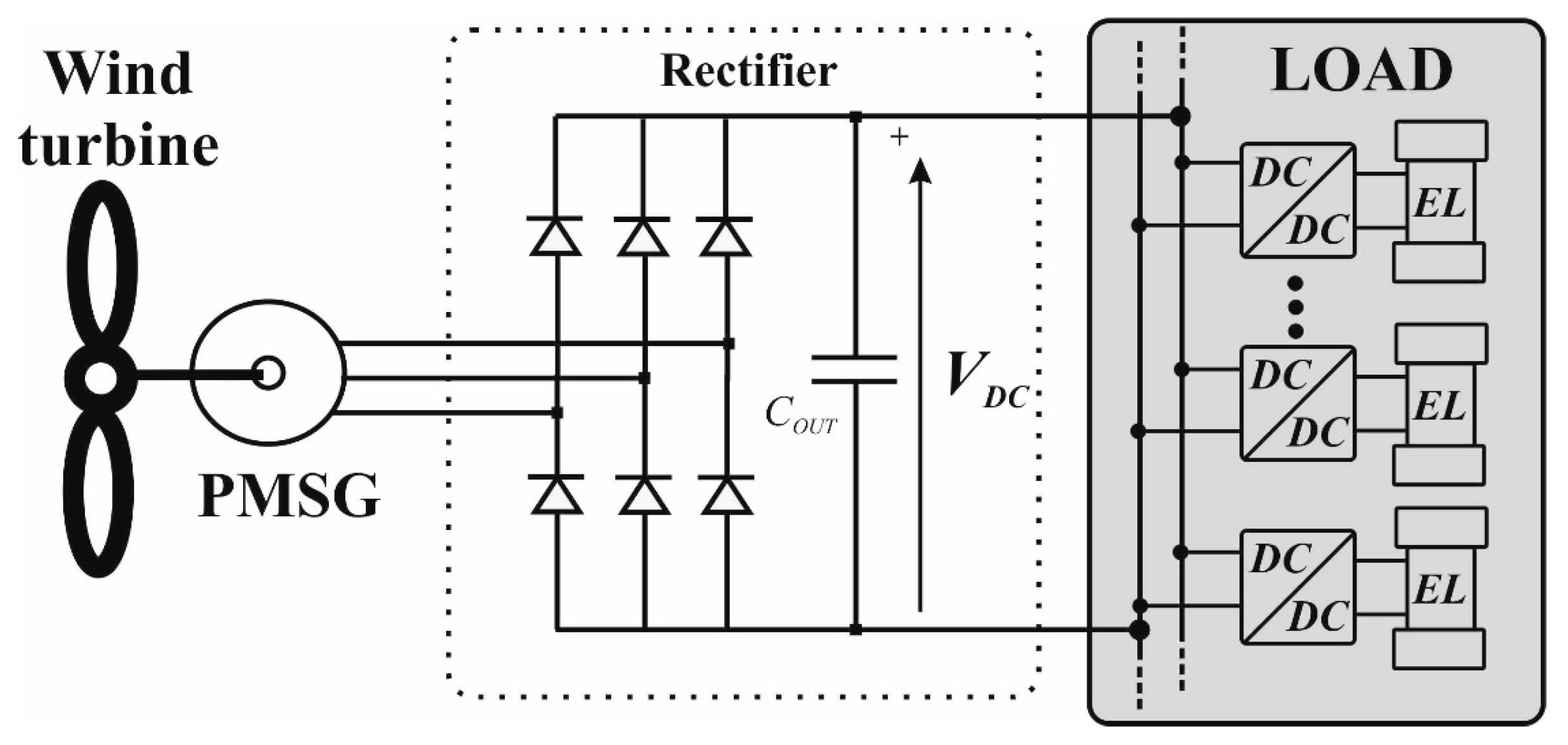
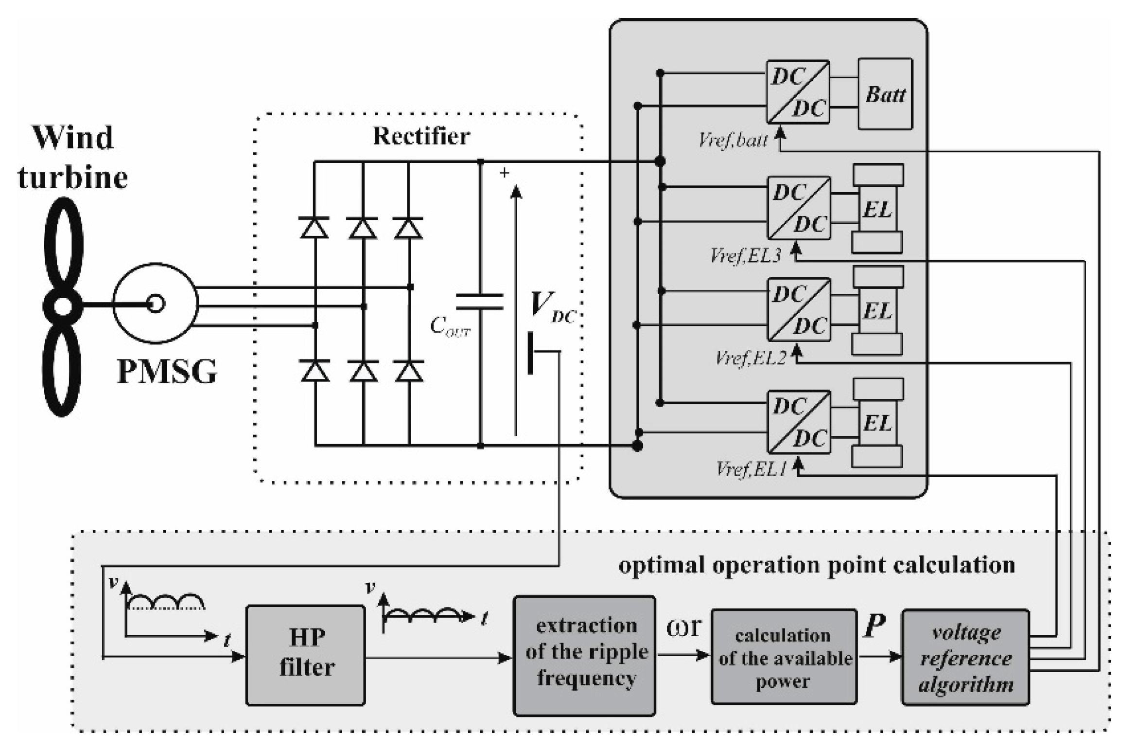
The investigated hydrogen production system is shown in
Figure 1 and the technical data of the wind turbine are summarized in
Table 1. The wind turbine is set up on the campus of the University of Technology in Longwy, France, a department of the University of Lorraine [
30]. The hydrogen production system is composed of a 5-kW wind turbine conversion system (WTCS), based on a permanent magnet synchronous generator (PMSG), a three-phase diode rectifier, and DC–DC converters connected to multistack PEM-ELs (every PEM-EL has a rated power of 400 W). The studied configuration is in the form of an array (parallel architecture, where each DC–DC converter is connected to a single PEM-EL), resulting in better reliability and flexibility from a control point of view. Based on
Figure 1, since the system is composed of three PEM-ELs, the total power of the multistack system is equal to 1200 W. As a result, each DC–DC converter can be controlled separately to transfer the energy from the WTCS to the different PEM-ELs. This enables the available electrical power to be managed between the different PEM-ELs through the DC–DC converters to optimize the hydrogen production. The AC voltage output of the PMSG strongly depends on the wind speed, and consequently its amplitude and frequency change according to the operating conditions (i.e., the wind speed). The three-phase diode rectifier is mandatory in order to convert the AC voltage from the PMSG into a DC voltage; unfortunately, a superimposed residual voltage ripple is generated by the rectifier. Generally, the DC bus voltage from a rectifier is quite high (as shown in
Figure 2), and the voltage changes according to the wind speed. Since the DC output voltage from the rectifier is higher than the rated stack voltage of a single PEM-EL (i.e., around 8 V), the most important feature required for the DC–DC converter is a high voltage reduction ratio [
30].
5. Converter Modeling and Characterization
The DC–DC converter, which interfaces with the output of the three-phase diode rectifier (DC bus) and the PEM-EL load, has several requirements: (a) a good efficiency value, (b) a lower ripple in the output current, (c) fast dynamic performance, and (d) fault robustness. The first requirement is needed to maintain a low pay-back time and to assess the advantage of the storage; it has to be noted that in this application, this must be achieved with a strong reduction of the rectified voltage available, using the turbine to supply the EL. As far as the ripple is concerned, it is known that harmonics superimposed onto the DC current worsen the specific energy consumption of the EL, as well as its reliability [
12,
26,
27,
28]. It is preferable to adopt a power converter with an inherently low harmonic content, since the passive or active filters used to suppress it are bulky [
12,
30]. The dynamic performance has to fit the power variation meaning that the dynamic behavior of the converter must be faster than the dynamic of the generator to preserve the DC bus capacitor by additional voltage stress. Finally, the fault robustness enhances the overall reliability. These requirements can be satisfied with the use of a SIBC. Unlike a classic interleaved DC–DC buck topology, in a SIBC, the two phases present a current ripple that is equal in amplitude but with opposing phase and the current ripple is canceled regardless of the duty cycle. A detailed description of this converter is given in [
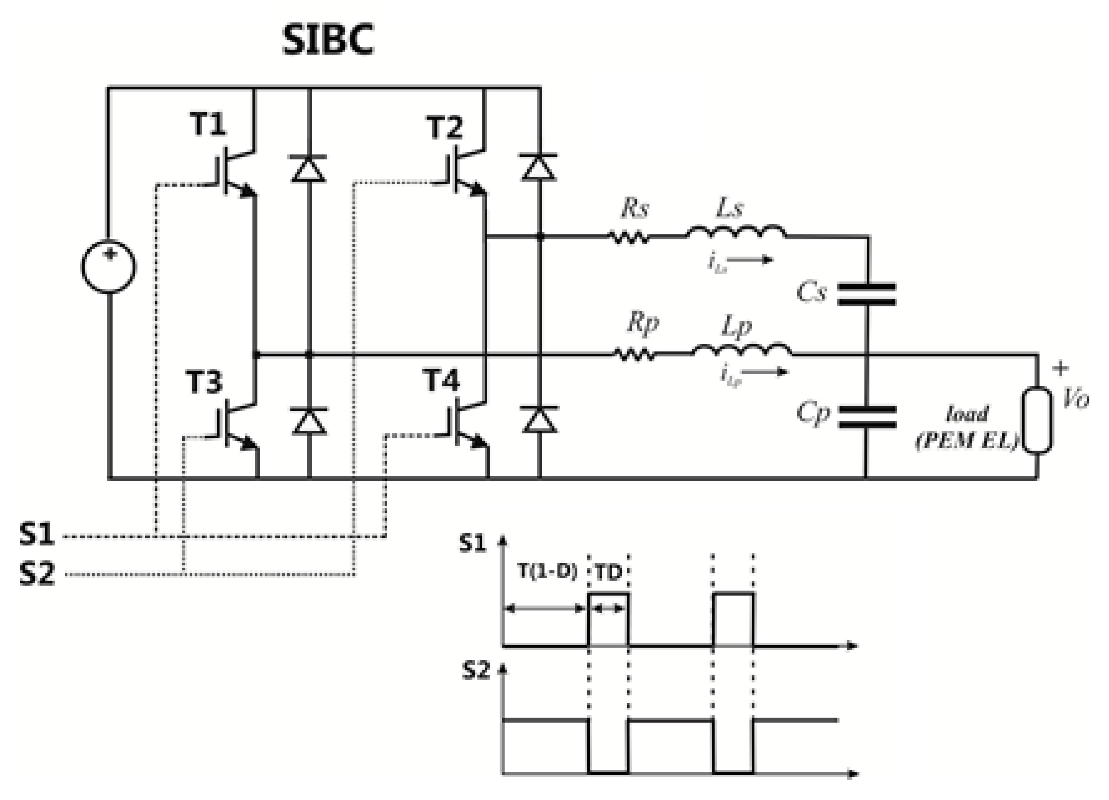
25]. The circuit of the proposed SIBC is shown in
Figure 7 [
30]. Where T1 and T3 are the power switches of the first leg, T2 and T4 are the power switches of the second leg, the other symbols are defined in Table 6.
The equivalent circuit model of the PEM-EL adopted in this work is represented in
Figure 8 (symbols correspond to
Figure 6) It takes into consideration the reversible voltage
Vi, the resistance of the membrane
Ri, and the RC branch modeling of the cathode reaction. The anode reaction was neglected as its reaction is slower than the cathode reaction and does not affect the dynamic behavior of the converter [
30].
It has to be emphasized that accurate knowledge of the PEM-EL model is crucial in order to define the dynamic performance of the system. Indeed, static models do not accurately represent the behavior of the EL, since the dynamic issues are neglected. A comparison of the voltage measured at the terminal of the PEM-EL and the voltages obtained by the static and dynamic models when a step current is supplied is shown in
Figure 9 [
30]. It can be noted that different shapes are obtained as a result of the step current in particular. Additionally, it has been demonstrated that the step response of the converter with a static or dynamic load is very different in terms of both the steady-state value and dynamic behavior [
25,
30]. In summary, with the static model, the step response shows an underdamped oscillatory response, whereas for the dynamic model the step response is overdamped, corresponding to a dominant negative pole. The open loop poles of the system composed of the SIBC converter and the EL are provided in
Table 4.
7. Experimental Validation of the Power Management Strategy
7.1. Test Rig Description
To assess the performance of the development power management strategy of the SIBC converter, an experimental test rig was constructed in the laboratory, as shown in
Figure 13. The experimental test rig was composed of the following components: (1) an autotransformer (input), (2) dSPACE ControlDesk software, (3) a pure water tank from SGWATER (Berlin, Germany), (4) a dSPACE DS1104 board from dSPACE (Bièvres, France), (5) an interface board, (6) an IGBT module stack from Semikron (Nuremberg, Germany) with a three-phase diode rectifier and SIBC, (7) inductive components (i.e.,
Lp,
Ls), (8) capacitive components (i.e.,
Cp,
Cs), (9) a PEM-EL (output) from Heliocentris (Berlin, Germany), (10) an E3N current probe from Chauvin Arnoux (Kehl, Germany), (11) an MTX 1032-B voltage probe from Metrix (Dubuque, IA, USA), and (12) a 4-channel digital oscilloscope from Keysight (Santa Rosa, CA, USA) [
30]. The power management strategy for the SIBC was developed in Matlab and Simulink environments, and then implemented into a dSPACE DS1104 board. The control of the SIBC converter was based on the DC bus voltage measurement (i.e.,
Vdc) at the output of the rectifier and was acquired using a voltage differential probe. The pulse-width-modulation (PWM) gate control signals used to control the SIBC were generated by the dSPACE DS1104 board.
However, the voltage levels of the generated PWM signals from the dSPACE board (0–5 V) were not fit to drive the Semikron SKHI 22 driver boards, which require 0–15 V. As a result, an interface board was used between the dSPACE board and the driver boards to convert the control signals from 0–5 V to 0–15 V. In the next subsection, experimental results are presented and discussed. The system specifications are summarized in
Table 6 [
30].
7.2. Experimental Results
The aim was for the experimental results to show both the voltage and current measured at the EL terminals in different operating conditions. In particular, the test in the steady-state condition showed the operation of the SIBC supplying the EL at rated power, whereas the test in transient conditions demonstrated the ability of the converter to vary the power delivered to the EL based on the power delivered by the turbine.
Figure 14 shows the voltage and current at the terminals of the EL with rated power. This occurs when the available power from the turbine exceeds the rated power of the EL; as explained before, the first EL was supplied with a power equal to 400 W, which represents the worst case for the SIBC converter. Despite this, both the voltage and current remain constant, and no appreciable ripple is noticeable, as can be noted in
Figure 15, which shows the same waveforms with AC coupling. It can also be noted that the voltage ripple measures about 4 mV from peak to peak. This is a satisfactory performance, since it maximizes the hydrogen production, improving the reliability of the EL [
26,
27,
28].
Figure 16 and
Figure 17 show the voltage and current in transient conditions. This occurs when the power available from the turbine varies; as a result, the control algorithm adjusts the voltage reference of the SIBC converter to track the power.
In particular,
Figure 16 shows a dynamic test performed when the available power varied from 50 to 160 W. This corresponds to a voltage reference level ranging from 5.2 to 6.5 V. It can be noted that the SIBC converter varies the supplied power in about 20 ms and the current rises from 8 to 23 A. The power measured at the terminals of the EL is lower due to the losses in the conversion chain.
Despite the abrupt power transient, the voltage does not exhibit any overdamping. This is another important result achieved by the control system of the converter; it preserves the EL since it avoids that a power step variation up to the rated power could produce a voltage higher than the rated voltage of the EL.
Finally,
Figure 17 shows a dynamic test performed when the available power decreased from 130 to 25 W. Additionally, in this case, the transient both of voltage and current was very fast, confirming the dynamic performance of the converter.
7.3. Discussion
The approach proposed in this paper consists of a distributed hydrogen production system, including multistack PEM-ELs. It aims to maximize the produced hydrogen by utilizing the operation of the ELs at rated power to achieve the best Faraday efficiency and to deliver a voltage with a reduced ripple. This approach is particularly advantageous when a RES is used as a power source, since the improvement of the conversion efficiency reduces the pay-back time, making the plant more efficient. The use of a RES to produce hydrogen minimizes the CO2 production; however, on the other hand, it imposes additional constraints for the designer. Differing from the supply from the grid, both the available power and the voltage vary during the operation, the rated power of the source usually overcomes the rated power of the EL, and the voltage depends on the source, often resulting in a significantly higher voltage than the voltage required by the EL. This is because a high source voltage lowers the delivered current and minimizes joule loss, which increases with the square of the current. Finally, tracking of the maximum power point (MPP) is required; this can be done using load management.
Both the efficiency of the converter and the EL are crucial in the conversion chain. In the case under study, the SIBC shows higher efficiency compared to a traditional buck converter, since the output voltage ripple is canceled by the auxiliary compensating leg. In a traditional buck converter, the output ripple could be lowered by either increasing the output capacitance or by using a high switching frequency. However, these approaches have some drawbacks. Indeed, the output capacitance is a short-circuit for harmonics that are dissipated into its internal resistance. Even if this is usually a small amount of power due to the low value of the internal resistance, this stresses the capacitance, producing heat that reduces its lifetime. Additionally, a high value of the output capacitance slows down the dynamic behavior of the converter. As a result, this could be problematic if the input power varies and the converter is forced to change its operating point. Slow dynamic behavior jeopardizes the operation of the MPP tracker, causing mismatching losses. Hence, a traditional buck designed with a low output ripple, achieved by increasing the output capacitance, will show poor dynamic behavior and a small amount of power loss in the same capacitance. On the other hand, the adoption of a high switching frequency has a dramatic impact on switching losses in power switches, since they depend linearly on this parameter. The improvement in efficiency can be estimated by considering the efficiency η, which can be written as:
Hence, if
Plost is diminished, for example by a factor 0 <
k < 1, it follows that the new efficiency
η’ is given by:
For example, a 20% reduction of the power loss (meaning k = 0.8) is achievable by lowering the switching frequency; this gives an increase in the efficiency of about 1%. It can be noted that this can be considered a good result, since the switching converters normally show an efficiency value higher than 93%. A more detailed discussion on improving the efficiency of the power converter can be found in [
33].
Regarding the influence of voltage harmonics on the efficiency of the PEM-EL, this is not directly addressed in literature, although [
12] and [
26,
27,
28] investigate this issue for alkaline water ELs. However, some general observations can be made. First of all, the response of an EL in terms of a periodic input signal fits a low-pass curve, which is shown in [
29] and related papers. This means that increasing the frequency reduces the impedance of the EL, progressively short-circuiting the harmonics. In addition, a variable current causes oscillation of the ions and consequent heat production, subtracting energy from the hydrogen production. Even if quantitative analysis is not possible from a qualitative point of view, it can be stated that even in the case of PEM-EL, the harmonics degrade the Faraday efficiency.
The Faraday efficiency is also optimized by sharing the power that is channeled to the array of ELs to operate them at rated power (meaning at the maximum current density). Since the Faraday efficiency increases with the current density, this allows the efficiency to be improved. In this case, as an example, typical phenomena occurring when electrons are diverted to the production of hydrogen peroxide are minimized. It can be noted that this is different from dividing the same power into equal parts for all the ELs, since in this case they would be operated with a lower current than the rated current, and hence with a lower Faraday efficiency, obtaining a lower amount of produced hydrogen.
A critical operating point for the system could be in proximity to the rated power of the EL when fluctuating power oscillates around this value (this could happen in the presence of wind gusts). To avoid switching on the next EL with a low amount of power, the battery can be used with a threshold at the minimum power that can be delivered to the EL. In any case, the delay introduced in estimating the power, as shown in the cycle of
Figure 12, avoids the trapping phenomena. A detailed study is out of the scope of this paper, however it will be discussed in future works.
The experimental setup proposed in this paper is designed at the laboratory scale, meaning a wind turbine with 5 kW of rated power and ELs with 400 W of rated power. However, it can be scaled to a higher power system. The bottleneck is caused by the SIBC converter, particularly by the maximum current allowed by the inductor, which is limited by joule loss. It is worth noting that our approach encourages the use of multiple converters in an array configuration, since it is not suitable to increase the power of a single converter, rather it is preferable to increase the number of converters to increase the overall power. Even if it seems that the number of components dramatically increases, it must be considered that their cost shows an increase lower than linear, particularly for the power inductor; hence, it is better to have multiple converters. Finally, the modularity of the system easily allows for the power to be increased, improving the overall reliability, since a fault in a single converter does not stop the plant and because maintenance can be properly scheduled.


