Abstract
In order to improve the suspension and torque performance of a bearingless flywheel machine, a new type of axial split-phase bearingless flywheel machine with a magnetic sleeve and pole-shoe tooth is analyzed and optimized as described in this paper. Based on the basic structure and working characteristics of the machine, the response surface methodology (RSM) and differential evolution (DE) algorithm are adopted to further optimize the parameters of the stator teeth of the machine to improve the radial space utilization and motor output performance. Firstly, the Box–Behnken design (BBD) and finite element analysis (FEA) are combined to select the representative optimization parameter combinations to establish the sample data space, and the response surface models of machine torque and suspension force are established using the least square method. Besides this, the DE algorithm is employed to obtain the optimal tooth profile parameter configuration for the multi-objective optimization of machine performance. Finally, the output performances of the machine before and after optimization are compared under initial and optimized winding turns. The results show that, compared with the initial structure, the average torque and suspension force of the optimized machine increase by 36.46 % and 108.22% respectively, which demonstrates the effectiveness of the tooth profile optimization method. At the same time, an experimental prototype is also produced, laying the experimental foundation for further practical exploration.
1. Introduction
Flywheel energy storage (FES) is a physical energy storage method that converts electrical energy into the high-speed rotating kinetic energy of the flywheel, which has the advantages of high power density, fast response time, long service life and simple maintenance, and has broad application prospects in distributed power sources, hybrid vehicles, aerospace and other fields [1,2,3]. However, there are still many technical difficulties that limit its application in engineering practice, among which the problems of suspension support and high-speed operation are particularly prominent. Traditional FES is mostly supported by magnetic suspension bearings to reduce system operating losses, but the structure has a large axial length, low critical speed, complex structure, and high maintenance costs [4]. On the basis of retaining the excellent characteristics of the magnetic bearing and the reluctance machine, the bearingless switch reluctance machine further improves the high-speed performance and operating efficiency through the active control of its suspension force. It is introduced into the FES to form a bearingless flywheel machine, which can reduce system loss and volume, improve suspension performance, critical speed and power density.
In the 1990s, the Japanese scholars Chiba A and Takemoto M first carried out related research and proposed a typical 12/8 dual-winding structure [5,6]. The machine adopts a double winding structure, and its air gap magnetic field is generated by the combined action of the current-carrying main windings and the suspension windings, which makes the suspension force and electromagnetic torque of this machine exhibit a strong electromagnetic coupling characteristic. Besides this, there is a dead zone in the suspension force and its control is difficult, which has become the main bottleneck restricting its entry into engineering applications. Recently, some scholars have tried to weaken the electromagnetic coupling from the perspective of the machine structure to achieve the high-speed and stable operation of the machine and have proposed various structures such as dual stators [7,8], hybrid rotors [9,10], hybrid stators [11,12], and permanent magnet bias [13,14]. The proposal of these new structures effectively weakened the electromagnetic coupling problem. However, when used for an FES system, there are still many shortcomings. For example, the dual stator structure does not easily integrate the machine and flywheel, and the windings of the internal and external stator structure experience serious temperature rise and heat dissipation, which leads to low efficiency when the machine is running at high speed. The hybrid rotor structure causes the axial length of the machine to still be long, and the critical speed of the flywheel is limited. The hybrid stator and the permanent magnet bias structure adopt the outer stator structure, the machine is not easy to integrate with the flywheel and the permanent magnet is on the outer stator side, which consumes more permanent magnetic materials and is not cost-effective. In [15], the authors proposed an axial split-phase topology, the structure of which uses its two-phase suspension windings distributed axially to achieve four radial degrees of freedom suspension of the rotor, greatly reducing the axial length of the mechanical or electromagnetic bearings at both ends and increasing the critical speed. At the same time, the inner stator structure is adopted, and the machine rotor and the flywheel are integrated, which reduces the size of the whole machine and further increases the stiffness of the flywheel rotor. However, the bias magnetic flux from the permanent magnet of this machine needs to frequently pass through the insulation layer between the silicon steel sheets, the axial magnetic path loss is large, and the utilization rate of the permanent magnet is low. Besides this, its stator adopts a rectangular tooth, which makes it difficult to wind more windings in a limited radial space, and the output power density of the machine is unsatisfactory. This paper proposes a novel axially split-phase bearingless flywheel machine with magnetic sleeve and pole-shoe tooth. By adopting a pole-shoe tooth, the slot space of the machine torque and suspension poles is effectively increased for more windings, as with the torque and suspension output. At the same time, a magnetically permeable sleeve is added to increase the utilization of permanent magnets and further enhance the suspension performance.
Previous studies have shown that the tooth profile parameters of machines have a significant effect on the output performance of machines, and optimizing the stator and rotor structure in a limited radial space to improve the radial space utilization and output performance has attracted the attention of many scholars [16,17,18]. However, due to the nonlinear coupling of the internal magnetic field, it is difficult to apply traditional analytical formulas directly, so scholars have tried different optimization methods, such as the extreme learning machine (ELM) [19], least squares support vector machine [20], response surface methodology (RSM) [21] and chaos harmony search [22] to achieve the optimal selection of parameters, all of which have achieved certain optimization effects, but there are still insufficient practical applications. For example, the ELM needs to directly use the finite element model multiple times to obtain the relationship between the machine performance and key structural parameters, and the calculation efficiency is low. The support vector machine has low modeling accuracy under small amounts of sample data, and the traditional response surface methodology has multiple sets of optimal solutions and verification is tedious and subjective, while the selection of parameters in chaos harmony search, such as the harmony memory considering rate and pitch adjusting rate, lacks a theoretical basis; thus, the parameter values are subjectively blind.
In summary, this paper proposes a novel machine structure and tooth profile parameter optimization method aiming at solving the shortcomings of the existing machine structure and parameter optimization method. Based on the basic structure and working principle of the proposed machine, the three-dimensional finite element analysis (FEA) model of the machine is established, and the Box–Behnken design method for finite element simulation is utilized; then, the RSM and comprehensive objective optimization function are adopted to construct the average torque and suspension force of the machine. Furthermore, the differential evolution (DE) algorithm is introduced to find the optimal solution of this objective function; that is, the optimal tooth profile parameter combination. Finally, the machines before and after the optimization are compared and analyzed to verify the tooth profile optimization method, and a prototype is designed for further experimental exploration.
2. Structure and Operating Characteristics of Proposed Machine
2.1. Basic Structure and Working Principle
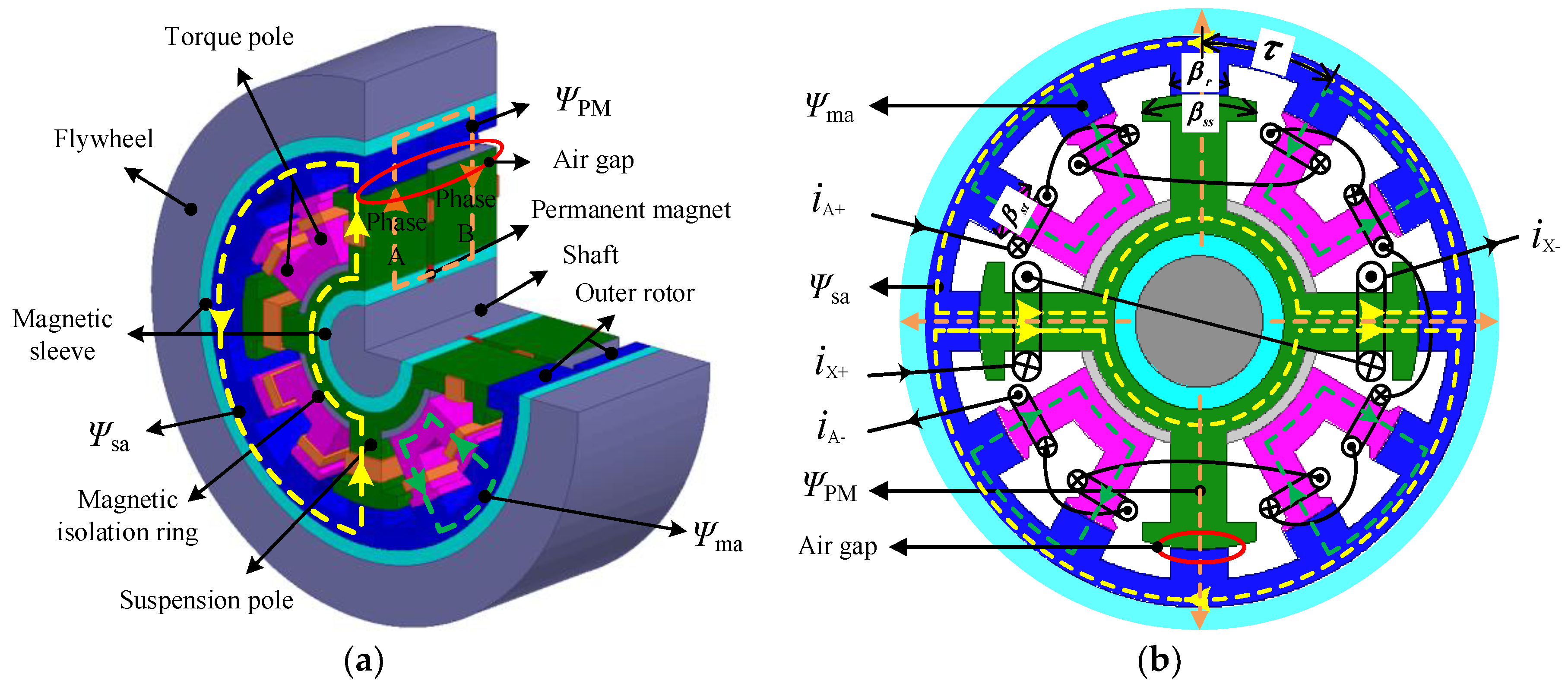
The structure of the axial split-phase bearingless flywheel machine with a magnetic sleeve and pole-shoe tooth is shown in Figure 1. As can be seen from Figure 1a, the machine adopts an inner stator and an outer rotor structure, and 12 equal-width rotor poles are evenly distributed on the inside of each phase rotor. The stator core of each phase is divided into eight narrow-tooth torque poles and four wide-tooth suspension poles. Both are shaped as pole-shoe teeth, where the width of the narrow tooth torque pole is equal to the rotor width , and the width of the suspension pole is equal to one rotor pole pitch . In addition, a magnetic isolation ring is provided between the wide-tooth suspension pole and the narrow-tooth torque pole, which weakens the coupling effect of the torque and suspension control magnetic circuit. The torque pole and suspension pole are respectively wound with torque control coils and suspension control coils. The control coils on the eight torque poles of each phase are connected in series to form a torque winding, and the suspension control coils on the two suspension poles are connected in series to form two sets of suspension windings in orthogonal directions. The axially magnetized permanent magnet between the two-phase stator cores provide bias magnetic flux for radial four-degree-of-freedom suspension forces. At the same time, in order to improve the axial magnetic permeability of the permanent magnet, a magnetic sleeve is added to the rotor and stator poles, thereby increasing the utilization of the permanent magnet, reducing the number of permanent magnets, achieving cost savings and increasing output.
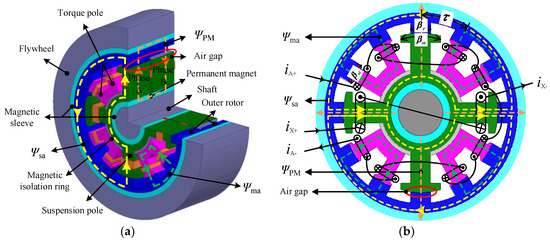
Figure 1.
Machine topology diagram: (a) structure and composition; (b) winding connection and magnetic circuit.
Figure 1b is a schematic diagram of the cross-section and magnetic circuit of the machine. In the figure, is the four-pole torque control flux generated by the current-carrying torque winding for each phase, is the two-pole suspension control flux generated by the current-carrying suspension winding, and is the bias flux generated by the axially-charged permanent magnet. By adjusting the torque and suspension winding current, machine rotation and radial four-degree-of-freedom suspension can be achieved.
2.2. Machine Operating Characteristics
When the proposed machine is operating, the torque current and suspension current usually need to be activated at the same time for rotor rotation and radial suspension. Considering that this paper mainly explores the radial suspension characteristics of the machine and the axial and angular constraints of the flywheel rotor, which are explained in more detail in [23,24,25], mainly including the structural constraint and decoupling control, this article will not repeat this explanation. In order to make a thorough inquiry of the working characteristics of the proposed machine structure, the FEA method is utilized to obtain the relevant electromagnetic characteristics.
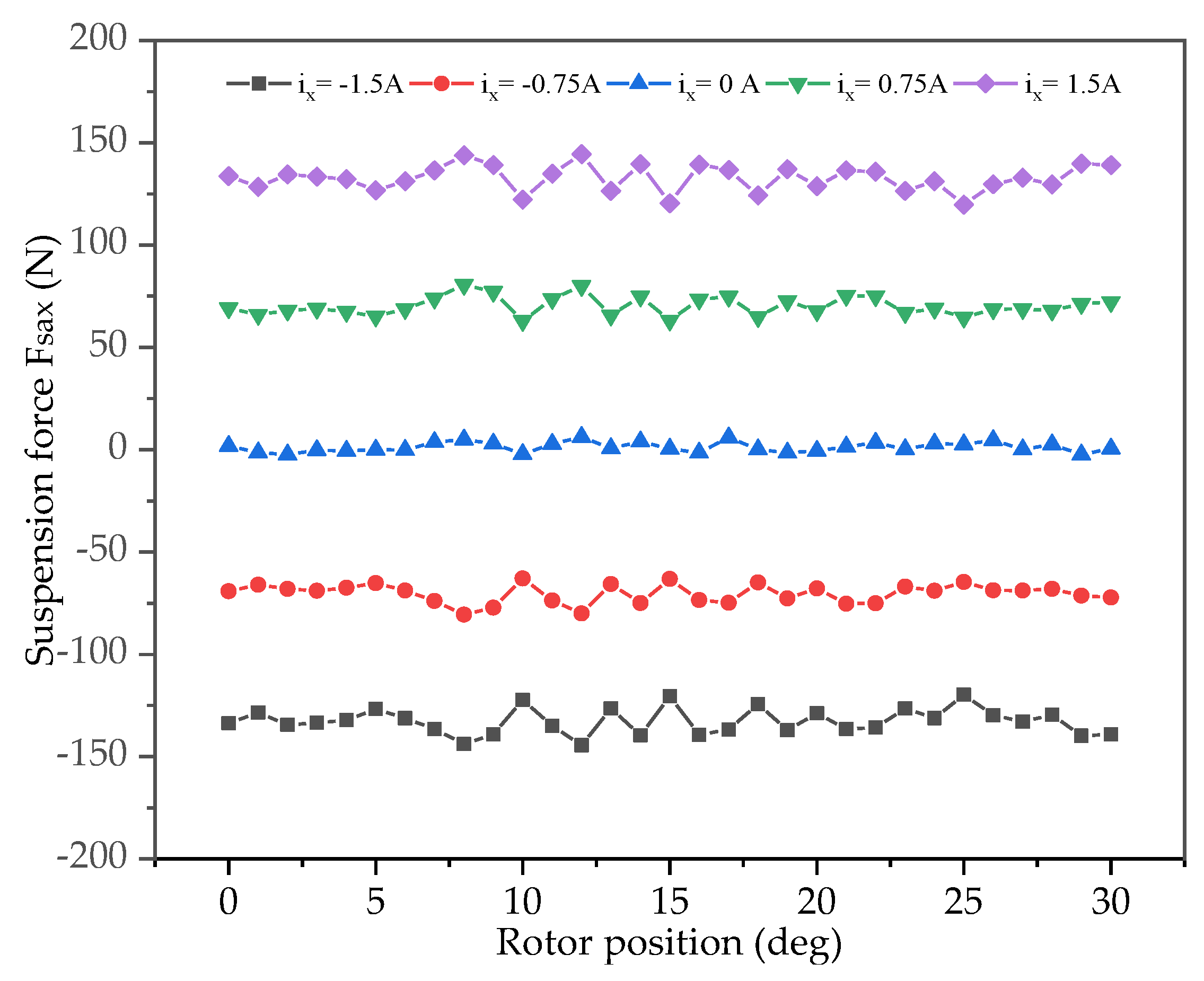
Figure 2 shows the basic suspension characteristic of the proposed machine with different currents in one cycle in the X-direction, but no current in the Y-direction suspension windings and the torque windings. It can be seen from Figure 2a that, when the suspension windings are supplied with current in the X-direction, the proposed machine structure can generate a suspension force at any position, and the suspension force changes little with the variety of the rotor angle under a given current, which shows that the proposed structure retains the advantages of the original wide-tooth suspension pole and extends the suspension force generation interval to a complete cycle so that there is no dead zone of suspension force.
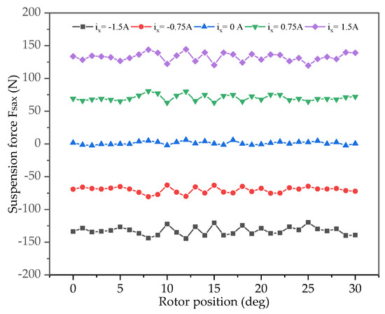
Figure 2.
Basic suspension characteristics of the proposed machine.
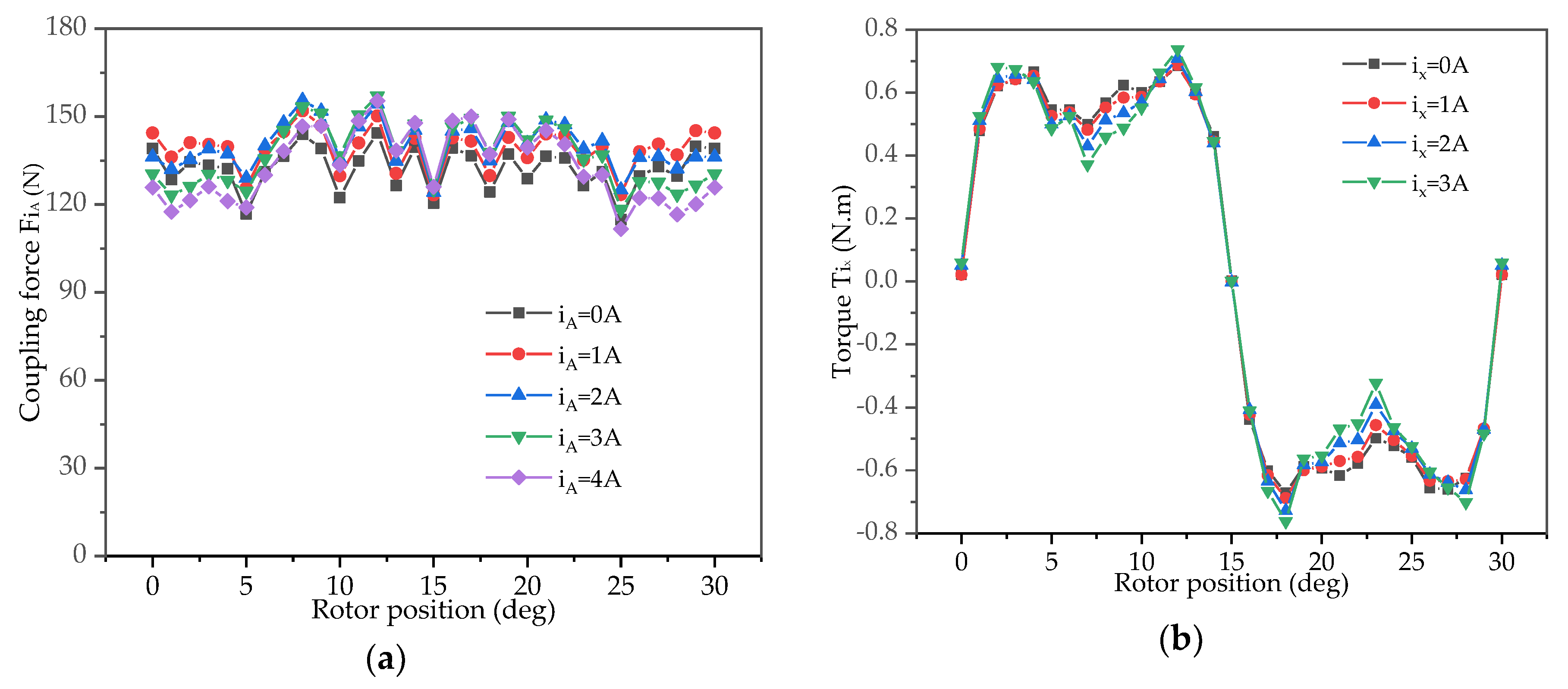
The coupling characteristics between the torque and suspension performance of the proposed machine are shown in Figure 3. Figure 3a shows the coupling force in the X-direction when the suspension windings pass a fixed 1.5 A current in the X-direction while the torque windings pass a 0–4 A current. As can be seen from the figure, the effect of different torque currents on the suspension force is relatively small compared to the suspension force produced by the suspension current . Taking = 1 A as an example, the average suspension force experienced by the machine in one cycle is 138.06 N, while the average suspension force under the current excitation of only = 1.5 A is 132.24 N, and the change rate is only 4.4%, from which we can be see that the proposed structure can effectively weaken the coupling effect of the torque winding current on the radial suspension force. Figure 3b shows the torque received by the machine when the torque winding current is 2 A, while the suspension windings in the X-direction pass a 0–3 A current. It can be seen from the results that the torque value hardly changes with various suspension winding currents, and the ratio of this value to the basic torque generated by the torque winding is so small that it can be ignored, which further illustrates that the proposed structure achieves the decoupling performance between the torque and the suspension force.
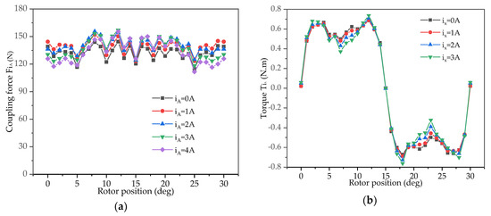
Figure 3.
Coupling characteristics between the torque and suspension performance of the proposed machine: (a) suspension force characteristic with a fixed current in suspension windings and various currents in torque windings; (b) torque characteristic with a fixed current in torque windings and various currents in suspension windings.
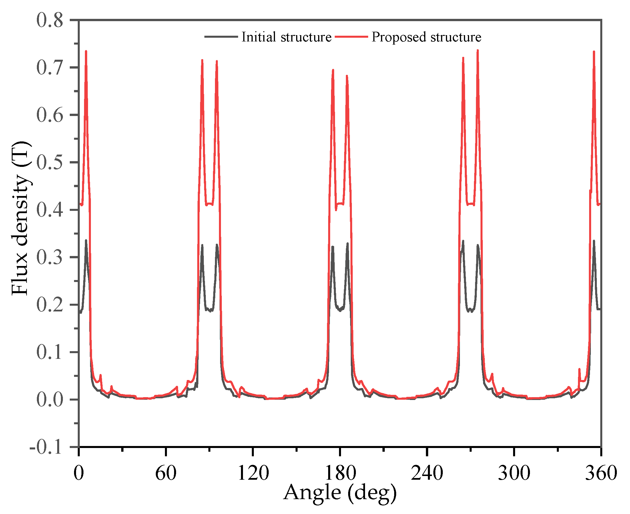
The comparison of the permanent magnet bias flux density before and after the addition of the magnetically permeable sleeve is shown in Figure 4. The calculation shows that, by adding a magnetic sleeve, the amplitude of the bias flux density from the permanent magnet is increased from 0.335 T to 0.736 T, and the magnetic permeability efficiency is increased by 119.7%. It is shown that adding a magnetically permeable sleeve can effectively reduce the magnetic circuit loss caused by the bias magnetic flux frequently passing through the insulating layer between the silicon steel sheets, greatly improving the utilization rate of the permanent magnet and verifying the excellence of the magnetically permeable sleeve.
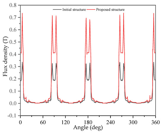
Figure 4.
Permanent magnet bias flux density before and after adding a magnetic sleeve.
It can be determined from the above analysis that the proposed machine structure avoids the dead zone problem of the suspension force by the wide-tooth structure of the suspension pole and realizes the decoupling between the suspension and torque magnetic circuit by setting a magnetic isolation ring. In addition, by adding a magnetically permeable sleeve, the utilization rate of permanent magnets is greatly increased; thus, the number of permanent magnets can be reduced to save the production cost of the whole machine. The above study explores the basic operating characteristics of the machine, verifies the effectiveness of the proposed machine structure, and lays a certain preliminary research basis for the next step of machine stator tooth profile optimization.
3. Tooth Profile Parameter Optimization Principle and Process
3.1. Response Surface Methodology
The essence of the RSM is to use the least square method to approximately establish a polynomial with a clear expression to express the implicit functional function between each response and the design variables, thereby facilitating the use of other excellent optimization algorithms to solve practical optimization problems [26], assuming the functional relationship between the optimization target and the selected design variables is as follows:
where represents the selected i-th basis function, and is the error. Assuming that the m design variables are used for experimental design and n experiments are performed, the response under n corresponding parameter combinations can be obtained, which is recorded as:
where , in which , is the value of the j-th basis function in the i-th experiment.
The matrix form can be expressed as
which can be abbreviated as
where ,,.
The estimated value of can be calculated using the least square method:
The fitted model of the final response surface function can be expressed as
where is the i-th row corresponding element of the column vector .
Studies have shown that when the independent variable changes in a relatively small interval, a low-degree polynomial fitting can obtain a better approximate mathematical model [17]. In engineering practice, if the response surface function is a polynomial of first degree, then Equation (6) is
where m is the number of selected design variables. Similarly, the widely used second-order response surface function can be written as
3.2. Differential Evolution Algorithm
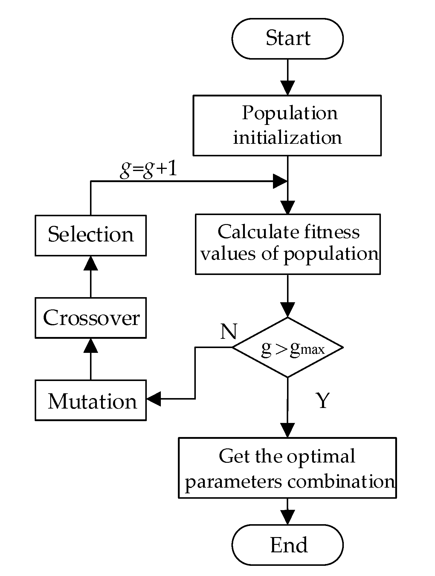
The DE algorithm is an emerging evolutionary computational algorithm. It performs a random heuristic search by simulating the “survival of the fittest” competition strategy in natural biological populations to approach or reach the global optimal solution of the optimization problem, which has the advantages of fewer undetermined coefficients, good robustness and global search, and has gained widespread attention in the field of parameter optimization [27,28,29]. The flow chart of the DE algorithm is shown in Figure 5, and the specific steps are as follows:
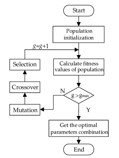
Figure 5.
Flow chart of the differential evolution (DE) algorithm.
(1) Population initialization: Randomly generate individuals to form the initial population, determine the maximum evolution number of the population, and let the i-th individual in the population be
where , is the number of individual independent variables, and , and are the upper and lower bounds of the j-th independent variable of the individual, respectively.
(2) Calculate the fitness values of the population: Bring in and calculate the corresponding fitness values of all individuals in the population and determine whether the current generation number g has reached the maximum evolutionary number : if it has not reached, continue with the subsequent operations; otherwise, this means that the parameter combination obtained is the best, and the optimizing process is ended.
(3) Mutation: Randomly select three different individuals from the population, multiply the difference between any two individuals by the scaling factor, and add the third individual to obtain the new mutant individual:
where is the new individual obtained by mutation, F is the scaling factor, represents the current generation, and .
(4) Crossover: Crossover between the new individual and the previous generation population with a certain probability, and generate a new individual to increase the diversity of the population:
where CR is the crossover probability and is a random integer between [1, d].
(5) Selection: Compare the fitness of the newborn and the previous generation, and select the individual with the best fitness to enter the next iteration:
where is the selected fitness function.
The above operations are repeated continuously until the maximum evolutionary number and the optimal parameter combination of the selected fitness function can be obtained.
3.3. DE Algorithm to Obtain Optimal Parameters of Response Surface Function
RSM combined with experimental design and mathematical modeling methods can fit the functional relationship between design variables and responses under a small number of experiment iterations and obtain the optimal output response and design variable combination [30]. However, practice shows that the optimal parameters automatically obtained by the traditional RSM using Design Expert analysis software finally provide multiple sets of design schemes. As the artificial selection of the optimal combination depends on experience and requires comparison and verification one by one, the operation is still tedious. Therefore, based on the approximate response surface function obtained by RSM, this paper obtains the optimal parameter combination by establishing the corresponding multi-objective optimization function and introducing the DE algorithm with a global search capability to avoid blind selection and improve the accuracy of optimal parameter combination, effectively simplifying the experimental verification process.
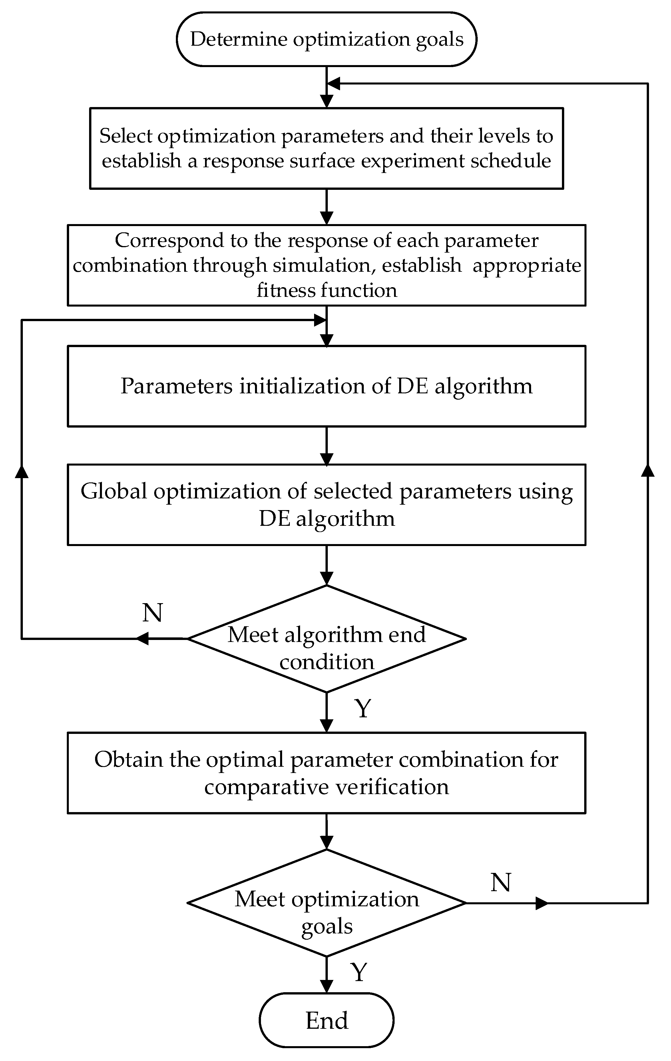
The detailed process of obtaining the optimal parameter combination of the multi-objective response surface model based on the DE algorithm is described below, and the optimization process is shown in Figure 6.
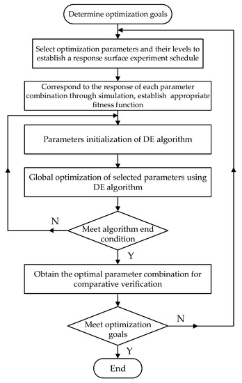
Figure 6.
Flow chart of the DE algorithm for optimal parameters.
(1) Determine the optimization goals;
(2) Select optimization parameter variables and their level factors to establish a response surface experiment schedule;
(3) The finite element simulation obtains the response under each experimental combination and analyzes and establishes the appropriate fitness function;
(4) Initialize the DE algorithm parameters, such as the maximum evolution number , the number of individuals in the population , the cross probability CR, the scaling factor F, the upper and lower bounds of the population individuals , and so on;
(5) The DE algorithm is adopted to calculate the fitness values of various groups based on the fitness function built, and global optimization is performed on the parameters to be optimized;
(6) Determine whether the current algorithm has met the end condition: if it is satisfied, proceed to the next operation; if not, then skip to step (4) and perform the operation again;
(7) Obtain the global optimal parameter combination, verify it by comparison experiments, and determine whether the optimization goal is met: if not, go to step 2) to re-optimize; otherwise, the obtained parameter combination is the selected optimal value.
4. Tooth Profile Optimization of Machine Stator
4.1. Select Optimization Parameters and Establish Response Surface Experiment Schedule
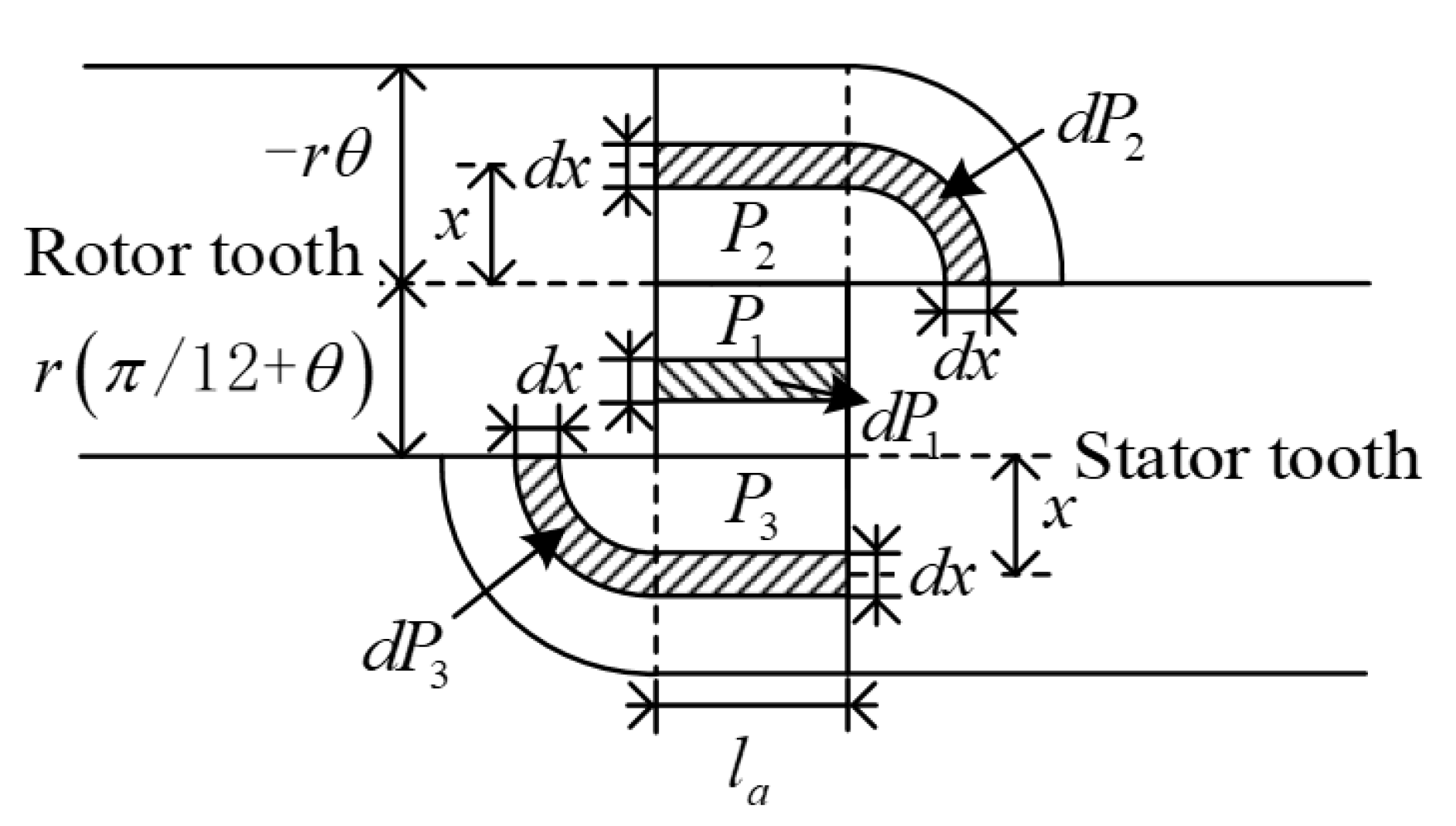
The machine suspension force and electromagnetic torque expressions derived from the equivalent magnetic circuit method and the electromechanical energy conversion relationship show that the air gap permeability between the poles of each stator and rotor has a significant effect on the electromagnetic performance output of the machine [31]. Figure 7 shows a schematic diagram of the air gap magnetic flux path under the stator and rotor poles of a machine. It can be seen from the figure that the tooth profile parameters of the machine stator will change the magnetic flux conduction path, thereby changing the magnetic circuit permeability and affecting the overall torque and suspension output performance. Consequently, in order to improve the magnetic circuit and radial space utilization of the machine, thereby further improving the machine torque and suspension output, it is necessary to optimize the parameters of the new machine stator with a pole-shoe tooth.
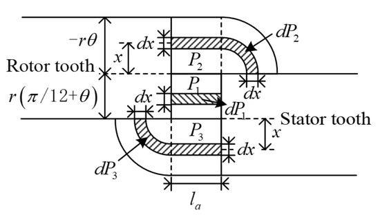
Figure 7.
Schematic diagram of air gap magnetic circuit division.
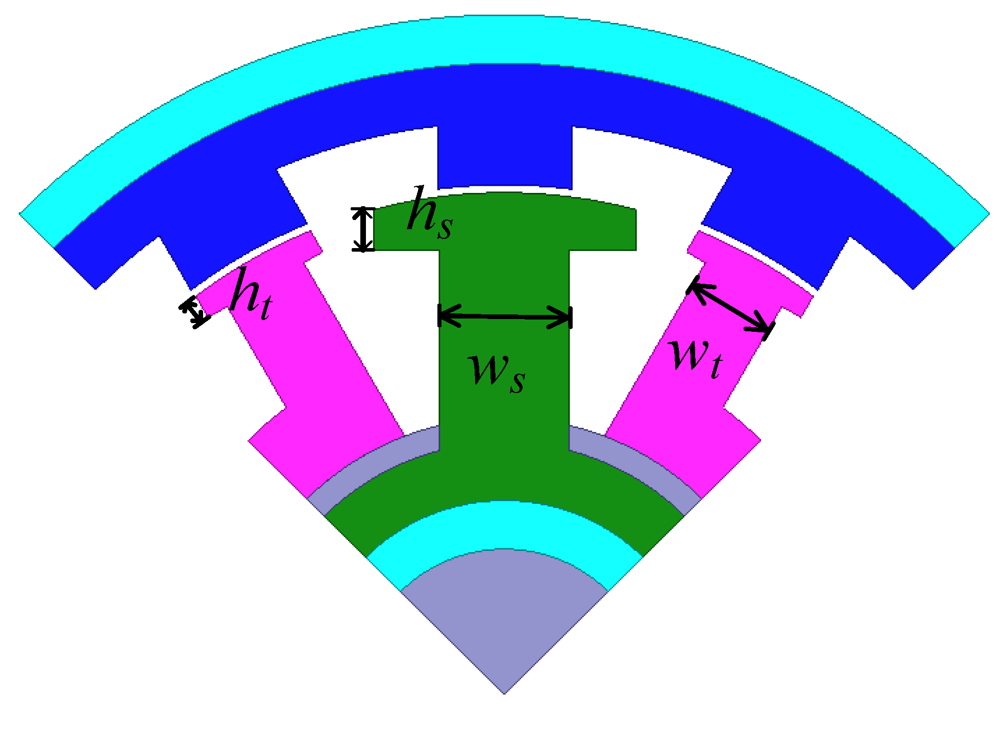
Based on the above analysis and existing related research [32,33,34], the stator tooth profile parameters selected in this paper are the torque pole tooth top ht, torque pole tooth width wt, suspension pole tooth top hs, and suspension pole tooth width ws, which are marked in Figure 8. The four tooth profile parameters selected increase in accordance with a fixed unit according to the actual size of the machine, and the three change levels of each parameter are shown in Table 1.
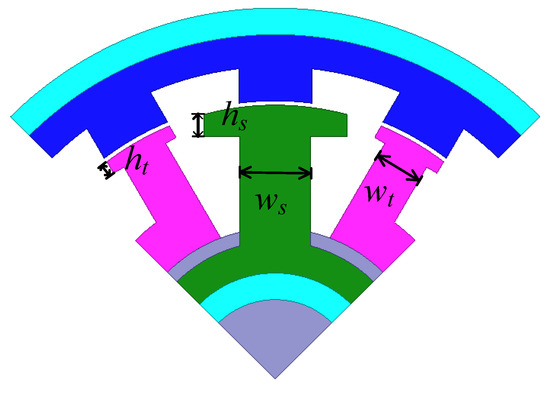
Figure 8.
Schematic diagram of machine tooth profile parameters.

Table 1.
Tooth profile optimization parameter levels.
Considering that the Box–Behnken design has fewer design points and lower operating costs than the traditional Center Composite design, this article establishes an experimental schedule based on the Box–Behnken design, as shown in Table 2. As can be seen from Table 2, each of the four tooth profile parameters has three level factors, with a total of 34 = 81 parameter combinations. If the traditional finite element optimization method is directly adopted, 81 sets of three-dimensional finite element models need to be established, which requires a large amount of calculation and takes a long time. In contrast, according to the Box–Behnken design, a representative combination of tooth profile parameters is selected, which requires only 29 finite element calculations, reducing the number of simulation experiments by 64.2%, greatly reducing the number of experiments required for simulation, and improving the efficiency of the optimization of machine tooth profile parameters.

Table 2.
Experiment schedule of tooth profile parameters optimization.
In view of the varying ranges of the optimized tooth profile parameters, the actual values of each parameter are coded to facilitate subsequent operations. The conversion rules are shown in Equation (13):
where is the actual value of the selected optimization parameter, and is the corresponding parameter encoding conversion value in Table 2.
4.2. Response Surface Modeling and Evaluation
According to the structural parameters of the machine shown in Table 3, a three-dimensional finite element model is established, and simulation is performed according to the experimental arrangement shown in Table 2 to obtain the average torque and the average suspension force in the X-direction of the machine under the corresponding tooth profile parameter combination. During FEA, the torque winding current is set to 3 A, and the suspension winding current in X-direction is 2.5 A, while the axial displacement of the machine is 0, and the angular constraint is 0–30° with step of 1°. The mathematical model of each response surface based on the quaternary quadratic response surface function is finally shown in Equations (14) and (15):

Table 3.
Machine fixed structure parameters.
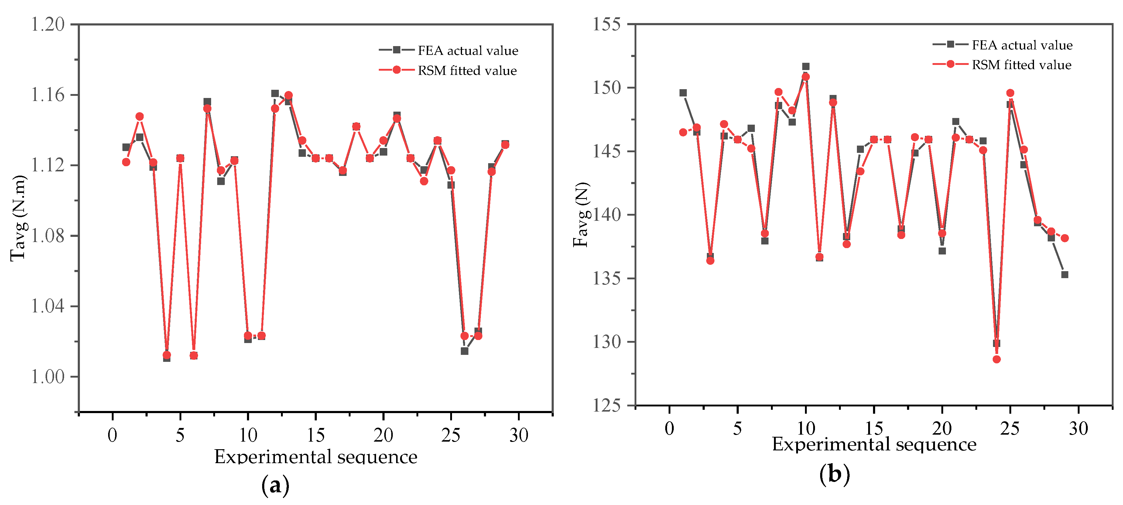
In order to evaluate the accuracy of the fitted model of each objective function, the P-test value, coefficient of variation Cv and decisive coefficient R2 are introduced to quantify the accuracy of the model. When the P value of the corresponding objective function is less than 0.05, the Cv value is close to 0, and the R2 value is greater than 0.9, this means that there is a significant relationship between the factor variable and the output response, and the fitted model has a higher regression accuracy. Table 4 and Figure 9 show the fitting accuracy of response surface models. Combining Table 4 and Figure 9, it can be seen that the P values of the obtained and response surface models are less than 0.0001, the Cv values are 0.9914 and 1.15, which are close to 0, and the R2 values are greater than 0.95. Each evaluation index meets the accuracy requirements, indicating that each objective function obtained has excellent fitting accuracy and high reliability, which is suitable for the next multi-objective optimization of machine performance.

Table 4.
Comparison of fitting accuracy indicators of response surface models.
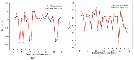
Figure 9.
Comparison of the finite element analysis (FEA) actual value and response surface methodology (RSM) fit value: (a) average torque ; (b) average suspension force .
4.3. DE Algorithm for Optimal Tooth Profile Parameters
In order to obtain the stator tooth profile parameter combination that achieves the optimal machine torque and suspension force performance, this paper takes the machine volume as the constraint condition and the maximum average torque and suspension force in one cycle as the optimization goals to construct the multi-objective optimization fitness function:
where and are the weight coefficients of the average torque and suspension force, respectively. In view of the magnitude difference between the machine torque and the suspension force in this paper, the two coefficients are respectively taken as , in order to make the suspension force value affect the degree of fitness function similarly.
The DE algorithm is used to optimize the multi-objective fitness function globally to obtain the optimal tooth profile parameter combination. At the same time, in order to verify the superiority of the selected DE algorithm, a particle swarm optimization (PSO) algorithm is introduced for comparison experiments. The initial parameters of the DE algorithm are shown in Table 5.

Table 5.
Initial parameters of the DE algorithm.
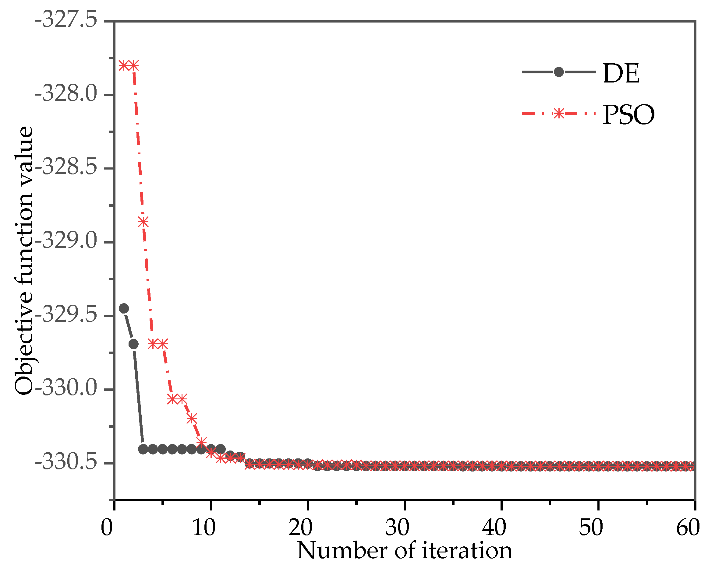
Figure 10 shows the results of the iterative optimization of DE and PSO. It can be seen that the DE algorithm has a faster convergence speed and higher optimization efficiency than the PSO algorithm, which effectively avoids the premature convergence of the traditional PSO algorithm and has a stronger multi-objective function extreme value optimization ability. The initial and optimal tooth profile parameter combinations obtained by the algorithm are shown in Table 6 (where the symbol ‘\’ represents no corresponding structural parameter).
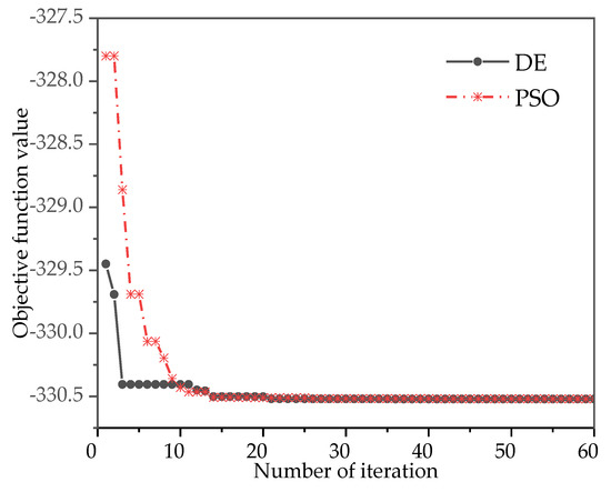
Figure 10.
Iterative optimization curve of DE and particle swarm optimization (PSO) algorithms.

Table 6.
Optimal tooth profile parameters.
4.4. Comparative Analysis
In order to verify the effectiveness of the proposed machine structure and parameter optimization, a comparative study of the machines before and after optimization is performed. To ensure the rationality of the comparative study, the key parameters such as the outer diameter, outer diameter of the permanent magnet, and air gap of the two machines before and after optimization are the same. In the comparative study, the verification is performed considering three aspects: the stator slot space of the machine, the output performance under the initial winding turns, and the optimized winding turns.
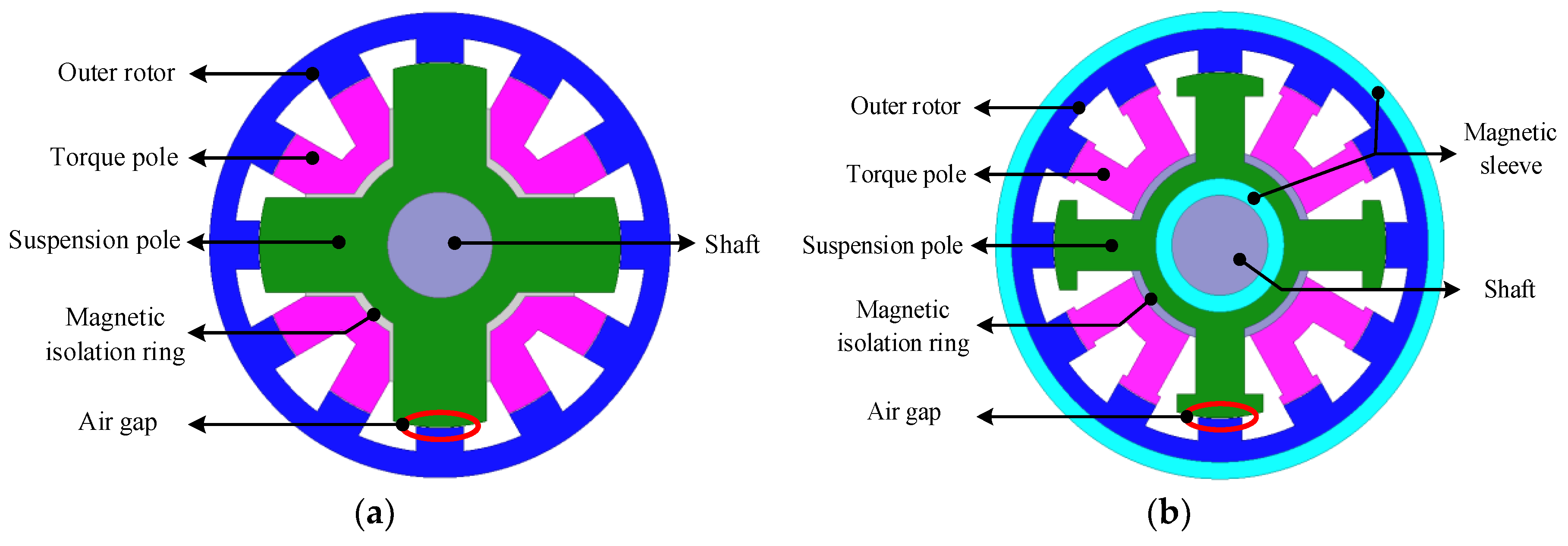
Figure 11 shows the radial section of the machine before and after optimization. It can be determined from the calculation of the torque and the suspension pole slot space that they are increased by 34.39 mm2 and 241.37 mm2 after optimization, which is an increase of 17.21% and 34.27%, respectively. In view of the number of turns of the original torque windings and suspension windings and the cogging space, the corresponding torque windings can increase the number of turns to 80 × 17.21% = 13.76, and the suspension windings can increase to 100 × 34.27% = 34.27. Taking into account the limitations of the existing processing technology, this paper takes 10 additional turns of the torque windings and 30 turns of the suspension windings for comparative simulation verification; that is, the optimized torque windings are increased to 40 turns, and the number of suspension windings is increased to 130 turns.
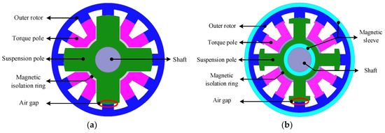
Figure 11.
Cross section of machine before and after optimization: (a) before optimization; (b) after optimization.
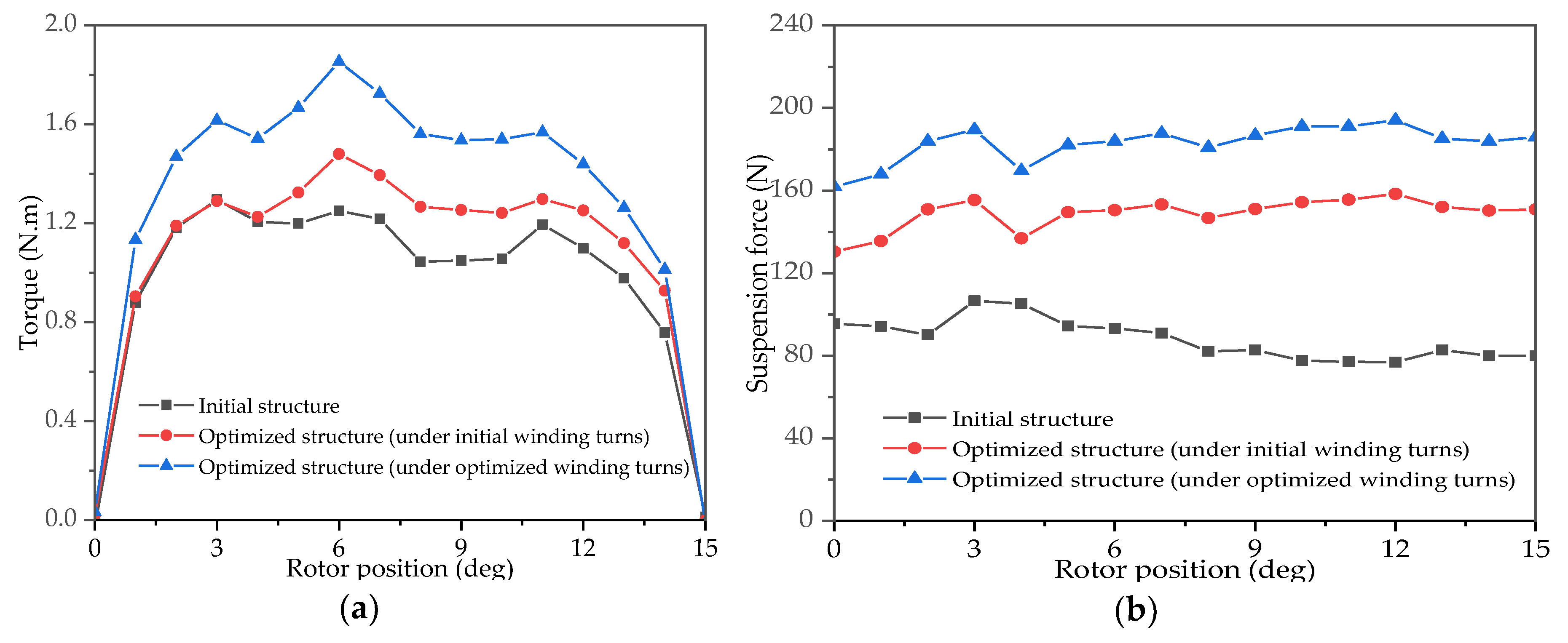
Figure 12 shows the average torque and suspension force output of the machine before and after optimization under the initial and optimized winding turns. Table 7 shows the numerical comparison of machine output performance before and after optimization. After further comparison and analysis, we can determine that under the initial winding turns, the average output torque and suspension force after optimization are increased to 1.07 N.m and 148.72 N, respectively. Compared with the average torque of 0.96 N.m and suspension force of 87.74 N before optimization, they have increased by 0.11 N.m and 60.98 N, respectively, and the increase ratios are 11.46% and 69.50%, which verifies the superiority of the proposed pole-shoe tooth structure over the original rectangular tooth. Under the optimized winding turns, the average torque and suspension force of the machine increase to 1.31 N.m and 182.69 N respectively, which increase by 0.35 N.m and 94.95 N, rising about 36.46% and 108.22%. In summary, the proposed structure and parameter optimization method can effectively further utilize the radial space of the machine and improve the machine torque and suspension performance.
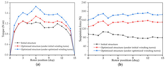
Figure 12.
Comparison of machine torque and suspension performance before and after optimization: (a) torque characteristic; (b) suspension force characteristic.

Table 7.
Numerical comparison of machine output performance before and after optimization.
A prototype of the proposed structure has been produced based on the obtained verified optimal tooth profile parameters, and the stator, rotor and overall structure are shown in Figure 13. At the same time, further experimental verification is underway.

Figure 13.
Optimized prototype stator, rotor structure and its overall diagram.
5. Conclusions
In order to further improve the suspension and torque output performance of the bearingless flywheel machine, a new axial split-phase bearingless flywheel machine with a magnetic sleeve and pole-shoe tooth is proposed. Based on the description of its basic structure and output characteristics, the stator tooth parameters of the proposed machine are optimized with the RSM and DE algorithm, and the output performance is compared and verified with the initial structure. Simulation analysis shows that, by adding a magnetic sleeve, the amplitude of the bias flux density from the permanent magnet has increased from 0.335 T to 0.736 T, increasing about 119.7%, while the average torque and suspension force have increased by 36.46% and 108.22% by the optimization of the improved pole-shoe tooth, respectively—all of which effectively illustrate the effectiveness and validity of the proposed machine structure and the optimization method of the tooth profile parameters.
6. Discussion
Combined with the results of the research in this paper, the authors aim to explore the following research topics in the future.
(1) The actual operation verification of the prototype: At present, further experimental verification is being carried out in an orderly manner. After the commissioning is completed, the actual operating performance of the prototype will be further analyzed and verified.
(2) Improvement of the used RSM: An accurate objective function model is the key to structural parameter optimization. Although the mathematical model between the response and the structural parameters established in this paper has met the corresponding accuracy requirements, it can be seen from Figure 9 that it can still be further improved. Therefore, we are going to make some improvements to the RSM used in this paper. We intend to use methods such as a dual response surface to establish a higher-precision response surface function and compare the accuracy and effectiveness of the two modeling methods.
(3) Multi-objective optimization of machine performance based on other structural parameters: This article only optimizes the machine stator tooth profile parameters based on the torque and suspension performance. However, during actual operation, other performance parameters of the machine, such as iron loss, torque ripple, and suspension force ripple, will also affect the machine’s stable operation. In order to further improve the high-speed and stable running performance of the machine, the next step is to further analyze and optimize the other corresponding machine structure parameters.
Author Contributions
Z.Z. contributed to the improvement of the machine structure and optimization framework; J.Z. collected the data and built the models; X.Z. and Y.Y. contributed to the FEA and numerical model. H.Z. contributed to the application and provided helpful advice. J.Z. wrote the paper and Z.Z. reviewed and edited the paper. All authors have read and agreed to the published version of the manuscript.
Funding
This research was funded by the National Natural Science Foundation of China (51977103, 51877101), the Postdoctoral Science Foundation Funded Project of China (2018M632201), the Six Talent Peaks Project of Jiangsu (GDZB-026), the Postgraduate Research & Practice Innovation Program of Jiangsu Province (SJCX18_0565, SJCX19_0525) and the College Students Science and Technology Innovation Fund of Nanjing Institute of Technology (TZ20190031).
Acknowledgments
The authors are thankful to anonymous reviewers for their valuable comments on this paper.
Conflicts of Interest
The authors declare no conflict of interest.
References
- Faraji, F.; Majazi, A.; Al-Haddad, K. A comprehensive review of Flywheel Energy Storage System technology. Renew. Sustain. Energy Rev. 2017, 67, 477–490. [Google Scholar] [CrossRef]
- Mohanned, Y.S.; Maruf, A.A.; Thomas, S.; Koyunlu, G.; Usman, U.; Adeshina, S.A. A Synopsis for Utilization of Energy Storage Systems in Distributed Power Generation. In Proceedings of the 2019 IEEE PES/IAS PowerAfrica, Abuja, Nigeria, 20–23 August 2019; pp. 204–208. [Google Scholar] [CrossRef]
- Ebadi, A.; Ji, J. Investigation & comparison of the integration of flywheel energy storage in hybrid electric and electric vehicles using bond graphs. In Proceedings of the 2017 20th International Conference on Electrical Machines and Systems (ICEMS), Sydney, Australia, 11–14 August 2017; pp. 1–6. [Google Scholar] [CrossRef]
- Zhang, T.; Liu, X.F.; Mo, L.H.; Ni, W. Modeling and control of magnetic suspension high-speed motor. Electr. Mach. Control 2018, 22, 98–104. [Google Scholar] [CrossRef]
- Takemoto, M.; Suzuki, H.; Chiba, A.; Fukao, T.A.; Rahman, M. Improved analysis of a bearingless switched reluctance motor. IEEE T. Ind. Appl. 2001, 37, 26–34. [Google Scholar] [CrossRef]
- Takemoto, M.; Chiba, A.; Akagi, H.; Fukao, T. Radial force and torque of a bearingless switched reluctance motor operating in a region of magnetic saturation. IEEE T. Ind. Appl. 2004, 40, 103–112. [Google Scholar] [CrossRef]
- Guan, Z.Y.; Zhang, F.G.; Ahn, J. High speed direct current compensation control for 8/10 bearingless SRM. In Proceedings of the 2012 IEEE International Symposium on Industrial Electronics, Hangzhou, China, 28–31 May 2012; pp. 1934–1939. [Google Scholar] [CrossRef]
- Xu, Z.Y.; Lee, D.; Ahn, J. Suspending force control of a novel 12/14 hybrid stator pole type bearingless SRM. In Proceedings of the 2012 15th International Conference on Electrical Machines and Systems (ICEMS), Sapporo, Japan, 21–24 October 2012; pp. 1–5. [Google Scholar]
- Li, D.X.; Xia, G.F.; Zhang, H.D.; Li, W.L. A Novel Bearingless Motor with Hybrid Rotor Structure and Suspension Force Control for Flywheel Energy Storage Supporting System. Trans. China Electrotech. Soc. 2015, 30, 48–52. [Google Scholar] [CrossRef]
- Sun, Y.K.; Liu, L.T.; Yuan, Y. Design of a New Type of Bearingless Switched Reluctance Generator. Small Spec. Electr. Mach. 2016, 44, 15–19. [Google Scholar]
- Xu, Z.Y.; Zhang, F.G.; Ahn, J. Design and analysis of a novel 12/14 hybrid pole type bearingless switched reluctance motor. In Proceedings of the 2012 IEEE International Symposium on Industrial Electronics, Hangzhou, China, 28–31 May 2012; pp. 1922–1927. [Google Scholar] [CrossRef]
- Xu, Z.Y.; Lee, D.; Ahn, J. Analysis and control of a novel bearingless switched reluctance motor with hybrid stator poles. In Proceedings of the 2013 IEEE International Conference on Industrial Technology (ICIT), Cape Town, South Africa, 25–28 February 2013; pp. 247–252. [Google Scholar] [CrossRef]
- Wang, H.; Liu, J.; Bao, J.; Xue, B. A novel bearingless switched reluctance motor with a biased permanent magnet. IEEE T. Ind. Electron. 2014, 61, 6947–6955. [Google Scholar] [CrossRef]
- Wang, H.; Bao, J.; Xue, B.; Liu, J. Control of suspending force in novel permanent-magnet-biased bearingless switched reluctance motor. IEEE T. Ind. Electron. 2015, 62, 4298–4306. [Google Scholar] [CrossRef]
- Zhu, Z.; Jiang, Y.; Zhu, J.; Guo, X. Performance comparison of 12/12 pole with 8/10 and 12/14 pole bearingless switched reluctance machine. Electron. Lett. 2019, 55, 327–329. [Google Scholar] [CrossRef]
- Choi, J.S.; Izui, K.; Nishiwaki, S.; Kawamoto, A.; Nomura, T. Topology optimization of the stator for minimizing cogging torque of IPM motors. IEEE T. Magn. 2011, 47, 3024–3027. [Google Scholar] [CrossRef]
- Kwack, J.; Min, S.; Hong, J. Optimal stator design of interior permanent magnet motor to reduce torque ripple using the level set method. IEEE T. Magn. 2010, 46, 2108–2111. [Google Scholar] [CrossRef]
- Kong, Y.; Lin, M.; Guo, R.; Li, N.; Xu, D. Design and optimization of an outer-rotor permanent magnet synchronous machine with an amorphous stator core. IEEE T. Appl. Supercon. 2018, 28, 1–5. [Google Scholar] [CrossRef]
- Sun, Y.K.; Yuan, Y.; Huang, Y.H.; Hu, W.H.; Xiang, Q.W.; Zhou, Y.H. Multi-objective optimal design of single winding bearingless switched reluctance motor. Electr. Mach. Control 2016, 20, 32–39. [Google Scholar] [CrossRef]
- Xiang, Q.W.; Sun, Y.K.; Zhang, X.H. Modeling and parameters optimal design of bearingless switched reluctance motor. Electr. Mach. Control 2011, 15, 74–79. [Google Scholar] [CrossRef]
- Li, Z.; Zhang, L.; Wang, Q.J.; Lun, Q.Q. Optimal design of structure parameters of three-DOF deflection type PM motor based on response surface methodology. Trans. China Electrotech. Soc. 2015, 30, 134–142. [Google Scholar] [CrossRef]
- Yuan, Y.; Sun, Y.K.; Huang, Y.H.; Zhou, Y.H. Harmony chaotic search optimal design of single winding bearingless switched reluctance flywheel motors. Trans. China Electrotech. Soc. 2015, 30, 180–188. [Google Scholar] [CrossRef]
- Sun, J.J.; Ren, Y.; Fang, J.C. Passive axial magnetic bearing with Halbach magnetized array in magnetically suspended control moment gyro application. J. Magn. Magn. Mater. 2011, 323, 2103–2107. [Google Scholar] [CrossRef]
- Fang, J.; Ren, Y. Decoupling Control of Magnetically Suspended Rotor System in Control Moment Gyros Based on an Inverse System Method. IEEE ASME Trans. Mechatron. 2012, 17, 1133–1144. [Google Scholar] [CrossRef]
- Ren, Y.; Fang, J. High-Precision and Strong-Robustness Control for an MSCMG Based on Modal Separation and Rotation Motion Decoupling Strategy. IEEE T. Ind. Electron. 2014, 61, 1539–1551. [Google Scholar] [CrossRef]
- Li, L.; Zhang, S.; He, Q.; Hu, X.B. Application of response surface methodology in experiment design and optimization. Res. Explor. Lab. 2015, 34, 41–45. [Google Scholar]
- Fan, Q.; Yan, X. Self-adaptive differential evolution algorithm with zoning evolution of control parameters and adaptive mutation strategies. IEEE T. Cybern. 2016, 46, 219–232. [Google Scholar] [CrossRef] [PubMed]
- Bouteldja, M.A.; Batouche, M. A study on differential evolution and cellular differential evolution for multilevel color image segmentation. In Proceedings of the 2017 Intelligent Systems and Computer Vision (ISCV), Fez, Morocco, 17–19 April 2017; pp. 1–8. [Google Scholar] [CrossRef]
- Goudos, S.K.; Deruyck, M.; Plets, D.; Martens, L.; Joseph, W. Optimization of power consumption in wireless access networks using Differential Evolution with eigenvector based crossover operator. In Proceedings of the 2016 10th European Conference on Antennas and Propagation (EuCAP), Davos, Switzerland, 10–15 April 2016; pp. 1–4. [Google Scholar] [CrossRef]
- Lee, J.H. Optimum shape design solution of flux switching motor using response surface methodology and new type winding. IEEE T. Magn. 2012, 48, 1637–1640. [Google Scholar] [CrossRef]
- Jia, H.; Wang, J.; Cheng, M.; Hua, W.; Fei, S. Mathematical model of radial suspending force for a new stator-permanent magnet bearingless machine. IEEE T. Magn. 2015, 51, 1–4. [Google Scholar] [CrossRef]
- Cai, Y.; Zhang, D.X. Simulation study on torque ripple reduction of a switched reluctance motor using new rotor tooth. Trans. China Electrotech. Soc. 2015, 30, 64–70. [Google Scholar] [CrossRef]
- Bao, J.; Wang, H.; Liu, J.; Xue, B. Self-starting analysis of a novel 12/14 type bearingless switched reluctance motor. In Proceedings of the 2014 IEEE International Conference on Industrial Technology (ICIT), Busan, Korea, 26 February–1 March 2014; pp. 866–871. [Google Scholar] [CrossRef]
- Chen, Y.; Zhuang, J.; Ding, Y.; Li, X. Optimal design and performance analysis of double stator multi-excitation flux-switching machine. IEEE T. Appl. Supercon. 2019, 29, 1–5. [Google Scholar] [CrossRef]
© 2020 by the authors. Licensee MDPI, Basel, Switzerland. This article is an open access article distributed under the terms and conditions of the Creative Commons Attribution (CC BY) license (http://creativecommons.org/licenses/by/4.0/).

