Article

Current Compensation in Grid-Connected VSCs using Advanced Fuzzy Logic-based Fluffy-Built SVPWM Switching

by
Yuvaraja Teekaraman
1,*,
Ramya Kuppusamy
2,
Hamid Reza Baghaee
3,
Marko Vukobratović
4,
Zoran Balkić
4 and
Srete Nikolovski
5
1
Information Communication Convergence Research Center, Gwangju Institute of Science & Technology, Gwangju 61005, Korea
2
Department of Electrical & Electronics Engineering, Sri Sairam, College of Engineering, Bangalore 562106, India
3
Department of Electrical Engineering, Amirkabir University of Technology, Tehran 15875–4413, Iran
4
Base 58 d.o.o., 31000 Osijek, Croatia
5
Power Engineering Department, Faculty of Electrical Engineering, Computer Science and Information Technology, University of Osijek, 31000 Osijek, Croatia
*
Author to whom correspondence should be addressed.
Energies 2020, 13(5), 1259; https://doi.org/10.3390/en13051259
Submission received: 19 December 2019 / Revised: 28 February 2020 / Accepted: 2 March 2020 / Published: 9 March 2020

Abstract

:
A main focus in microgrids is the power quality issue. The used renewable sources fluctuate and this fluctuation has to be suppressed by designing a control variable to nullify the circulating current caused by voltage fluctuations and deviations. The switching losses across power electronic switches, harmonics, and circulating current are the issues that we discuss in this article. The proposed intelligent controller is an interface between a voltage-sourced converter and a utility grid that affords default switching patterns with less switching loss, less current harmonic content, and overcurrent protection, and is capable of handling the nonlinearities and uncertainties in the grid system. The interfaced controller needs to be synchronized to a utility grid to ensure that the grid–lattice network can be fine-tuned in order to inject/absorb the prominent complex reactive energy to/from the utility grid so as to maintain the variable power factor at unity, which, in turn, will improve the system’s overall efficiency for all connected nonlinear loads. The intelligent controller for stabilizing a smart grid is developed by implementing a fuzzy-built advance control configuration to achieve a faster dynamic response and a more suitable direct current link performance. The innovation in this study is the design of fuzzy-based space vector pulse width modulation controller that exploits the hysteresis current control and current compensation in a grid-connected voltage source converter. By using the proposed scheme, a current compensation strategy is proposed along with an advanced modulation controller to utilize the DC link voltage of a voltage source converter. To demonstrate the effectiveness of the proposed control scheme, offline digital time-domain simulations were carried out in MATLAB/Simulink, and the simulated results were verified using the experimental setup to prove the effectiveness, authenticity, and accuracy of the proposed method.

1. Introduction

In the present scenario, due to the depletion of conventional sources, the use of renewable energy resources plays a vital role in distributed generation. The amalgamation of various renewable and conventional sources has led to the development of hybrid grids. The energy generated from renewable energy sources (RESs) cannot be used directly as the power fluctuates. Therefore, energy storage systems (ESSs) play a vital role in keeping the supply constant. The use of ESSs suppresses only the DG power fluctuations and realizes the maximum required load. However, stabilization and optimization in grid-connected mode are major concerns. Due to public, governmental, and academic interest in distributed/renewable energy resources (DERs/RERs) and ESSs, important technical challenges have arisen regarding the integration of these resources into the existing utility grid such that reliable power can be injected without violating grid codes and standards. A microgrid is a small-scale power grid in the low voltage range that can operate in either grid-connected or islanded (autonomous) mode and must be able to locally solve energy issues and enhance flexibility. In recent years, power electronics have played an important role in developing this revolutionary technology. Power electronic converters are used as the interface between a distributed generation system and a microgrid, and, in this regard, voltage source converters (VSCs) have frequently been utilized. Furthermore, the designed inversion systems are connected to the filter circuit to eliminate the harmonics. ESSs act as intermediary devices between the generation system and the load demand [1,2,3]. In most situations, current-regulated pulse width modulation (PWM) is used for VSCs. In a connected grid, the impedance between the load and the generation system is large and, hence, this impedance is sufficient to reduce the circulating current. However, the voltage sources of the generation in a microgrid cause variations due to climatic conditions. This deviation in voltage causes the circulating current to cross the permissible limit. Hence, the entire grid structure has to be maintained to avoid any malfunctions and to avoid instability in the grid-connected system [4].
VSCs operate based on a specified fuzzy-regulated vector control technique that regulates the active/reactive energy at both ends [5]. Active filters are used at the output of the inversion system to suppress the unwanted ripples and harmonics due to unbalanced and nonlinear loads [6]. The current and voltage are controlled separately under dynamic mode conditions. Therefore, the controlling time is increased, and this issue can be resolved by adding a compensation technique by computation delay. This generates reference currents for the designed ASPF. This reference current is obtained from a varying load and modified for delay compensation. This makes VSCs capable of linking feeble alternating current (AC) networks without using nearby voltage sources [7,8,9]. Regarding power reversal, the direct current (DC) voltage polarities remain the same for a VSC-built transmission framework and the power exchange relies only on the course of the DC current [10].
PWM and its derivatives, such as sinusoidal PWM (SPWM) and space vector PWM (SVPWM), are the most popular signaling techniques for power electronic converters. The use of SPWM enables the customer to utilize only 78.5% of the DC link voltage. The switching of power electronic switches is subject to stress when the modulating wave of the normal frequency magnitude is higher than the high-frequency carrier wave. Hence, a third harmonic injection is done with the modulating wave to generate a pulsing pattern at all times. SVPWM is the most prominent technique and allows the user to utilize the entire DC link bus voltage without any losses [11]. The fuzzy-built SVPWM method is designed to act as a free control structure. The SVPWM switching technique has many benefits, such as working toward a high and steady exchange frequency, having an ideal switching pattern, having a great symphonious range, and providing a fantastic DC link bus utilization rate. In a grid-connected VSC, the SVPWM controller deals with grid harmonics, nonlinearity in the structure, and insufficient intrinsic overcurrent protection [12].
Along with a broad spectrum, PI controllers are used to outline the current control plan in VSCs based on SVPWM. These controllers are difficult to implement when the system has parametric uncertainties, nonlinearities, and load variations [13,14,15,16,17]. To solve this problem, a fuzzy-built SVPWM controller is proposed in this paper. The fuzzy set hypothesis can be used to model regular uncertainties and manage the plant and control variables [18]. In the proposed strategy, a Z-source voltage hotspot converter is presented that exploits Tom’s perusing fuzzy-built current SVPWM PI controller in a grid-connected VSC [19,20,21,22].
Vector-based modulation and regulation techniques use adaptive and nonlinear management strategies [23]. VSCs offer bidirectional power flow, constant DC voltage, and the elimination of harmonics. VSCs also have complementary passive filters for a variety of power quality issues [24,25]. The concept of vector management uses fuzzy logic management for current and DC voltage control in VSCs [26].

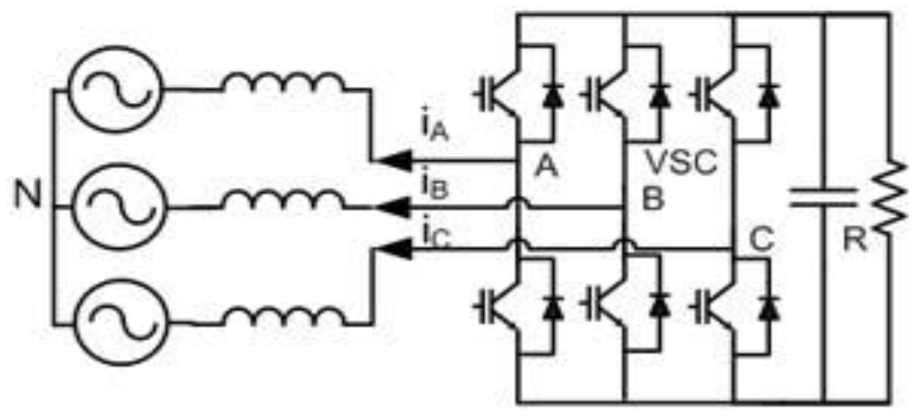
2. Z-Source Voltage Source Converter
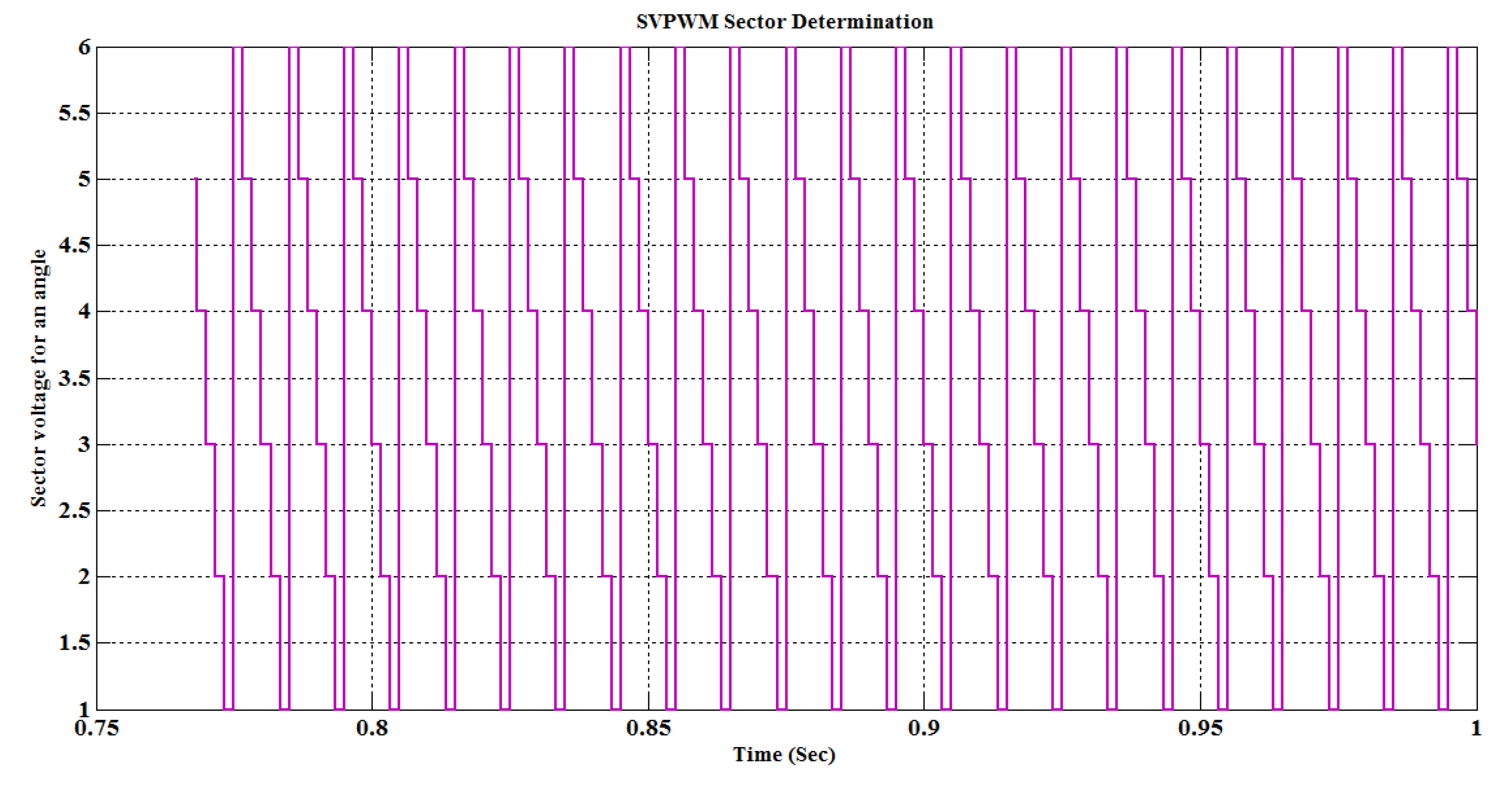
The Z-Source VSC control technique used in µgrid is the most flexible and authenticated control technique and is more sensitive than the previously reported control techniques with proper AC voltage regulation. The ZSource over a VSC utilizes an interesting impedance system with a converter principle circuit and a power source. A two-port network structure with a split inductor needs more capacitors over the X-shape network. As shown in Figure 1, this is an extended impedance source (Zsource) coupled to a converter circuit.
The ZSource impedance network connected to a VSC can provide a source of electric power to supply the grid in case of a reactive load at the grid side or absorb the excess complex reactive power from the AC grid towards the ZSource to maintain the VPF at unity. The DC bus voltages are associated with those of an energy source. The three-phase AC voltage is provided as an RMS value as stated in Equation (1). The voltages VA, VB, and VC are the RMS values of the voltages and are represented as VR(RMS), VY(RMS), and VB(RMS), respectively.
V A = V R ( R M S ) = V m sin ( ω t ) V B = V Y ( R M S ) = V m sin ( ω t 2 π 3 ) V C = V B ( R M S ) = V m sin ( ω t + 2 π 3 )
The direction of the current flow in the VSC is represented as per Equation (2).
I = ( V a c V V S C ) X
If VVSC < Vac, the entire network structure works with respect to the leading current (the connected nonlinear load contains the capacitive source of power). The VSC absorbs the excess amount of complex reactive power at the load and the direction of the current flow is from the load to the source. If the network structure is working under a lagging load, VVSC > Vac, some of the power is supplied from the VSC to the grid so as to maintain the VPF at unity. In this case, the VSC functions as a capacitor and the VSC supplies the capacitor-sensitive control power to the AC utility grid as shown in Figure 2.
The ZSource VSC shown in Figure 2 contains an LC input and output filter with common ground. The VSC, when switched under various pulses, encounters switching ripples, and these ripples in the input current are reduced with the use of the LC filter constructed under the ZSource. A reduced snubber value is added across each switching device of the VSC to limit voltage overshoot. The snubber used across the switches provides commutation paths during dead times. An LC output filter in ZSource is required to reduce the large harmonic component that occurs at the output load. The designed ZSource is smaller in size when compared with other ZSource topologies.

3. SVPWM Converter

3.1. Space Vector Representation

The space vector representation of the three-phase voltages Va(t), Vb(t), and Vc(t) with a space circulation of about 120° is given by Equation (3):
V = 2 3 [ V a ( t ) + a V b ( t ) + a 2 V c ( t ) ]
where
a = e j ω t = e j 2 π / 3 = cos ( 2 π 3 ) + j sin ( 2 π 3 )
a = e j 2 ω t = e j 4 π / 3 = cos ( 4 π 3 ) + j sin ( 4 π 3 )
V A = V R ( R M S ) = V m sin ( ω t ) V B = V Y ( R M S ) = V m sin ( ω t 2 π 3 ) V C = V B ( R M S ) = V m sin ( ω t + 2 π 3 )
Substituting Equation (6) into Equation (3), we define the orthogonal system voltages as given in Equation (7) and Equation (8). The orthogonal system voltages V α and V β are calculated from the three-phase system voltages by using Clarke’s/Park’s transformation.
V α = 2 3 V a 1 3 V b 1 3 V C
V β = 1 3 V b 1 3 V c
The angle between V α and V β is represented by θ and is calculated as shown in Equation (9).
θ = tan 1 ( V β V α ) ; θ [ 0 , 2 π ]
The above-mentioned relations provide us with the idea of transforming stationary 3Ø voltages into 2Ø voltages, determined along the orthogonal plane in the stationary reference frame (STRF) (αβ coordinates), by using Clarke’s transformation as shown in Figure 3. V A , V B , V C are the 3Ø Voltages with respect to the stationary reference frame, which was mapped on to a 2Ø orthogonal αβ coordinate. The three 3Ø sinusoidal voltages are considered to be a vector V a b c = ( V a , V b , V c ) T .
Each stage of the voltage vector needs a stage shift of about 120° to be different from the other components, as given in Equation (10) and Equation (11).
V a = V sin ( ω t + φ ) V b = V sin ( ω t + φ 2 π / 3 ) V b = V sin ( ω t + φ + 2 π / 3 )
V α β 0 = S X V a b c
where S is a transformation matrix, which is defined in Equation (12):
S = 2 3 [ 1 1 2 1 2 0 3 2 3 2 1 2 1 2 1 2 ]
We substitute Equation (12) and Equation (10) into Equation (11) to obtain the orthogonal voltages in a three-axis system (the α component, the β component, and the no-load components) as given in Equation (13).
V α β 0 = 2 3 [ 1 1 2 1 2 0 3 2 3 2 1 2 1 2 1 2 ] × V [ sin ( ω t + φ ) sin ( ω t + φ 2 π / 3 ) sin ( ω t + φ + 2 π / 3 ) ]
This Ø VSC needs eight switching states, which are produced by eight space vectors using the SVPWM vector Vk and are given by Equation (14). This equation produces six active states that produce a non-zero voltage vector. The two non-active states produce a zero-voltage vector.
V k = { 2 3 V D C e j ( k 1 ) π / 3 k = 1 , 2 , 3 , 4 , 5 , 6 0 k = 0 , 7

3.2. The Calculation of the Duty Cycle in SVPWM

To determine the on and off moments of the switches Ton and Toff, the sampling period Ts has to be determined. The signal Vref needs to be turned on throughout the period Ts, and, thus, the principal voltage vectors V1 and V2 need to be turned on during T1 and T2, respectively. It proceeds similarly for each bit-vector that is accessible in the state space. The voltage vectors are given by Equation (15):
V 1 = V e j θ 1 = V ( cos θ 1 + j sin θ 1 ) V 2 = V e j θ 2 = V ( cos θ 2 + j sin θ 2 ) V r e f = V e j θ r e f = V ( cos θ r e f + j sin θ r e f )
where
T s V r e f = T 1 V 1 + T 2 V 2
Substituting Equation (15) into Equation (16), we have
T S [ V r e f cos θ r e f V r e f sin θ r e f ] = [ V 1 cos θ 1 V 2 cos θ 2 V 1 sin θ 1 V 2 sin θ 2 ] [ T 1 T 2 ]
Rearranging Equation (17), we have
T S [ V r e f cos θ r e f V r e f sin θ r e f ] = [ V 1 cos θ 1 V 2 cos θ 2 V 1 sin θ 1 V 2 sin θ 2 ] [ T 1 T 2 ]
Consequently,
[ T 1 T 2 ] = T S [ V 1 cos θ 1 V 2 cos θ 2 V 1 sin θ 1 V 2 sin θ 2 ] 1 [ V r e f cos θ r e f V r e f sin θ r e f ]
T 1 = T s = V r e f V 1 × sin ( θ 2 θ r e f ) sin ( θ 2 θ 1 ) T 2 = T s = V r e f V 2 × sin ( θ r e f θ 1 ) sin ( θ 2 θ 1 )

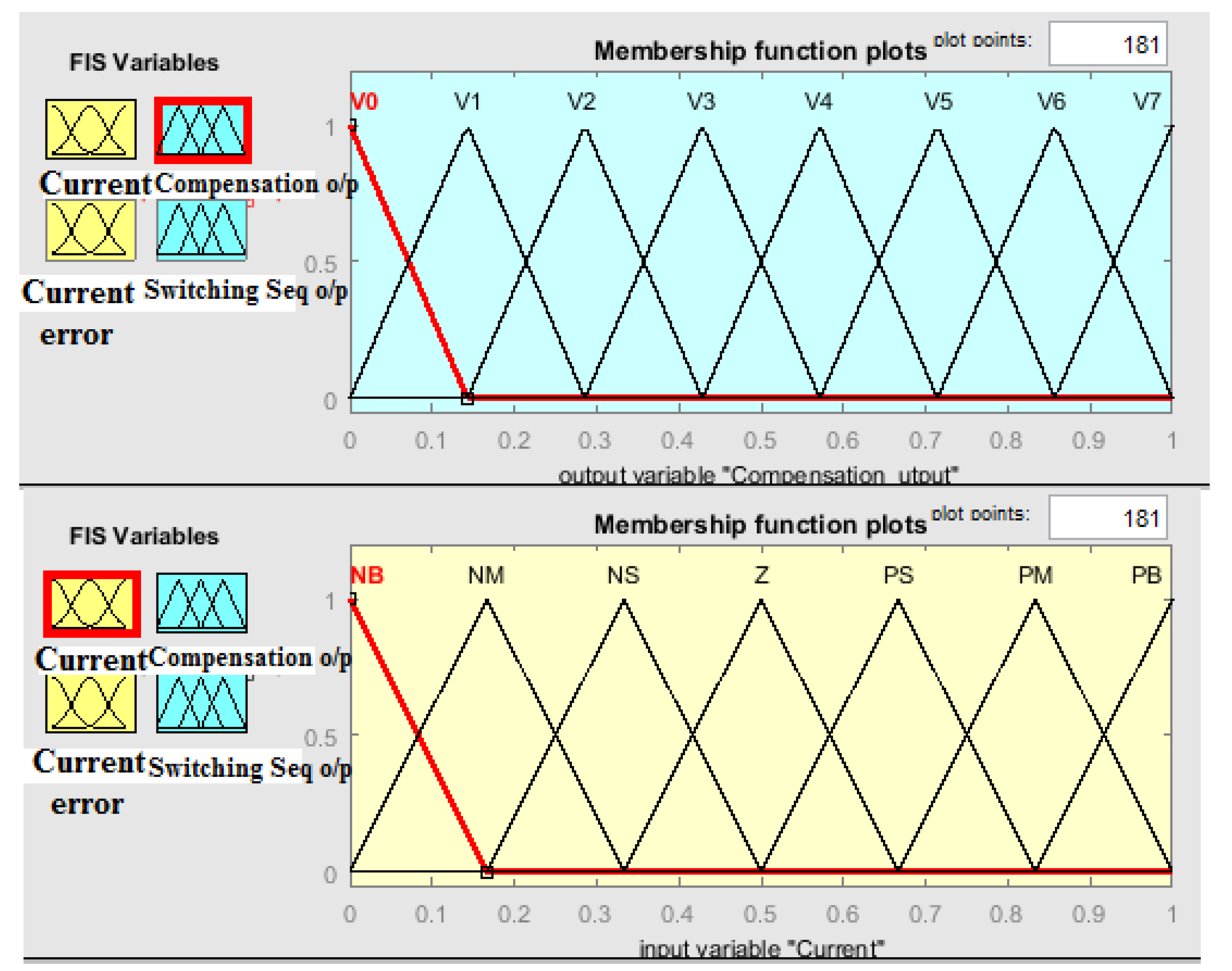
4. SVPWM Fuzzy Controller

The nonlinear SVPWM controller does not provide a suitable current control scheme in a VSC-based microgrid. Hence, in the proposed scheme, a fuzzy-logic-based controller is presented to realize the control objectives so that SVPWM will provide complete control over the converter. The fuzzy-built SVPWM controller is also adaptable, which provides it with desirable performance for VSCs in microgrids with nonlinear loads.
A block diagram of a Z-source VSC with a fuzzy-logic-based SVPWM controller is shown in Figure 4. This controller provides an acceptable decoupled current slip and compensates for it to realize programmed advanced exchange control over the converter’s output for a fitting run through a delay. The VSC’s output is associated with the utility grid and the three-phase grid voltages given by Equation (21).
V g a = V m cos ( ω t + φ ) V g b = V m cos ( ω t + φ 2 π 3 ) V g c = V m cos ( ω t + φ + 2 π 3 )
The grid voltage is represented in the synchronous reference frame (SYRF) (dq coordinates) by using Park’s transformation as given in Equation (22).
[ V g d V g q ] = [ cos ( ω t ) sin ( ω t ) sin ( ω t ) cos ( ω t ) ] [ V g α V g β ]
In the STRF, we have
[ V g α V g β V g 0 ] = 2 3 [ 1 1 2 1 2 0 3 2 3 2 1 2 1 2 1 2 ] × V [ cos ( ω t + φ ) cos ( ω t + φ 2 π / 3 ) cos ( ω t + φ + 2 π / 3 ) ]

5. Fuzzy Controller for Current Error Compensation

On account of the drawbacks of the SVPWM controller, the SVPWM controller with fuzzy logic is implemented in a grid-tied VSC. As illustrated in Figure 5 and Figure 6, the fuzzy controller includes two inputs, namely current and current error, and one output. The fuzzy current compensation controller (FC3) examines the input current and current error and transforms the calculated dynamic error into legitimate qualities in the range of −1 to +1 by using the fuzzy rules stated in Table 1 for one cycle of operation. Table 1 lists the framed Fuzzy Rules by which the current compensation output and switching sequence are obtained. The control decision topology of the proposed FLC-based scheme is illustrated in Figure 7.
The normalized current input and the current error section are designated with a triangular membership function. Figure 7 illustrates the fuzzy control structure’s output to compensate for the current to the grid structure. A fuzzy rule is specified for the current parameters that are connected under the grid based on a current normalized function. The membership function for the current compensation network is shown in Figure 8.

6. Simulation Results

The simulation test results are presented in this section to show the effectiveness of the proposed fuzzy-logic-based SVPWM controller. Offline digital time-domain simulations were carried out in MATLAB/SIMULINK and experimental tests were conducted to verify the results of the simulations. Information about the three-phase stationary reference outline was transformed into dq coordinates by using Park’s transformation. The reference voltage is shown in Figure 9.
Measurements of the complex real and reactive power on the nonlinear load side were simulated and are shown in Figure 10. On the load side, the measured real power was 50 KW, and the measured reactive power was 25 W. On observing the real and reactive power of the grid system, it was clear that most of the power at the output was active power, the observed voltage and current were in phase, as shown in Figure 11, and, hence, the power factor at the load side was almost unity.
The implementation of SVPWM defined the voltage vector and the reference voltage vector as traveling between the axis. The sector determination of the vector voltages is shown in Figure 12. The sectors of the reference voltages are likely to follow the determined sectors shown below.

THD Analysis

Figure 13 shows the THD results from the VSC using the SVPWM controller. The analysis was carried out using a fast Fourier transform (FFT) with the Power graphical user interface (GUI). The FFT analysis of the VSC using the SVPWM controller was performed for one cycle among 50 cycles at a converter voltage of 323.9 V. The analysis resulted in a THD factor of 0.82%.
Figure 14 shows the simulation test of the THD on the load side. The simulation test was carried out in the FFT window of the Power GUI for one cycle at a voltage of 168 V. The load yield will be 168 V at the fundamental frequency with a THD of about 0.05%. On observing the results, it was clear that the proposed controller produced better efficiency and a harmonic distortion of 0.82% in the converter section and 0.05% on the load side when compared with the conventional SVPWM controller.

7. Experimental Results

The hardware configuration of an SVPWM-controlled solar inverter is shown in Figure 15. The solar panel was kept outside, and the rating of the solar panel is as shown in Table 2.
The solar output was connected to the inverter board. The fuzzy-logic-based SVPWM controller controlled the inverter board. The inverter board was configured with six IGBT switches (model: FGB20N60SFD) controlled by the SVPWM controller. From the experimental circuit, it was observed that, at Tc = 25 °C and an inductive load of 250 W, the increase in time was 15 ns and the loss across the switches was 0.17 mJ during off-time and 0.35 mJ during on-time. At a full load of 1.5 KW, it was observed that the increase in temperature was 125 °C and the losses across the switches were 0.58 mJ during off-time and 0.20 mJ during on-time. The power switches were working with less than six active states. The voltage and current were more or less in phase, in which the measured power factor was unity. The Vout of the inverter was found to have no distortion and, hence, the system was able to attain the maximum efficiency of 90.5% at a load of 1.25 KW. As the amount of distortion was reduced, the system’s performance and its efficiency improved.
The generated inverter output was connected to a nonlinear inductive load with a rating of 3 KW. The VSI was made to operate as a STATCOM to compensate for the reactive power. A digital modulation technique was designed and used to switch the inversion system. The digital switching technique provides advantages as it works with ‘0’ and ‘1’. This technique provides higher precision, enhanced system performance, and better system stability and flexibility. The use of digital SVPWM allows the entire system to utilize 100% of the DC link bus voltage. The system was tested for THD, and the THD value was found to be less than 2.7% for a linear load and less than 3.15% for a nonlinear load. The response of the system under dynamic conditions was less than 2.5% at full load with a recovery time of <1.25% (<25 ms). The THD of the grid-connected inverter with the SPWM controller was 0.71%, whereas the THD of the grid-connected inverter with the SVPWM controller was 0.11%. Hence, the overall efficiency of the inverter was improved. The result of a comparative analysis of the grid-connected solar inverter using the SPWM controller and the grid-connected solar inverter using the SVPWM controller is shown in Table 3. The system’s performance was tested with different load ranges, and its efficiency is tabulated in Table 4. The efficiency in the case of the SPWM controller was low, with a value of 75.91%, due to the lower utilization of the bus voltage and a more distorted output. The distorted output had an average THD value of 0.71%. The maximum efficiency was attained when using the SVPWM controller as the bus voltage was completely utilized. With the SVPWM controller, the THD value was reduced to an average of 0.11% and the system’s efficiency was around 90.5% at maximum load.

8. Conclusions

In the present study, a microgrid model with a fuzzy-logic-based SVPWM controller was designed to provide excellent output performance, optimized efficiency, and high reliability. The effect of the integration of the system was tested with an installed solar system with an induction motor as a load. The designed control structure’s effectiveness was tested in MATLAB/SIMULINK in terms of circulating current, dynamic response, and THD. A Z-source converter with an input/output filter was presented to reduce the large harmonic component. The dynamic response of the system was good under transient conditions. The experimental results show that the ZSource converter produced no voltage spike across the switch. The utilization of the DC bus voltage was increased by 15% and the harmonic distortion was decreased compared with the conventional PWM technique. By using SVPWM fuzzy switching, the peak switch current at the time of switching and losses in the switches can be reduced. Therefore, there is less stress on the converter’s controls and the perceptible noise can also be minimized. Effectual means for power transformation between the source and the load in a wide range of electric power conversion applications was developed with the design of the Z-source VSC with a fuzzy-logic-based SVPWM controller. The system’s THD was tested, and it was found that the THD value was less than 2.7% for a linear load and less than 3.15% for a nonlinear load. The response of the system under dynamic conditions was less than 2.5% at full load with a recovery time of <1.25% (<25 ms). The THD of the grid-connected inverter with the SPWM controller was 0.71%, whereas the THD of the grid-connected inverter with the SVPWM controller was 0.11%. Hence, the overall efficiency of the inverter was improved. The results of a comparison, in terms of THD level, between the SPWM and SVPWM controllers in islanding mode are presented in Table 3. The designed fuzzy-logic-based SVPWM controller provides an increase in bus voltage utilization, less current harmonic content, a reduction in voltage spikes across the switches, a reduction in harmonic distortion, an improvement in power quality, and a completely stable system.

Author Contributions

All authors contributed equally to the publication of this article, including to the design of the target model, the validation of the numerical model, the parametric study, the analysis, and the writing of the manuscript. All authors have read and agreed to the published version of the manuscript.

Funding

This research received no external funding.

Conflicts of Interest

The authors declare no conflicts of interest.

References

  1. Priyadarshi, N.; Padmanaban, S.; Bhaskar, M.S.; Blaabjerg, F.; Sharma, A. Fuzzy SVPWM-based inverter control realisation of grid integrated photovoltaic-wind system with fuzzy particle swarm optimisation maximum power point tracking algorithm for a grid-connected PV/wind power generation system: Hardware implementation. IET Electr. Power Appl. 2018, 12, 962–971. [Google Scholar] [CrossRef]
  2. Djema, M.A.; Boudour, M.; Agbossou, K.; Cardenas, A.; Doumbia, M.L. Fuzzy Logic Based Reactive Power Management for Autonomous MicroGrid. In Proceedings of the IEEE 27th International Symposium on Industrial Electronics (ISIE), Cairns, Australia, 13–15 June 2018. [Google Scholar]
  3. Jena, S.; Babu, B.C.; Naik, A.K.; Neeraja, D. Fuzzy Logic Based SVPWM Current Controller for inverter interfaced distributed generation system. In Proceedings of the International Conference on Process Automation Control and Computing, Coimbatore, India, 20–22 July 2011. [Google Scholar]
  4. Siwakoti, Y.P.; Peng, F.Z.; Blaabjerg, F.; Loh, P.C.; Town, G.E.; Yang, S. Impedance Source Network for Electric Power Conversion—Part II: Review of Control and Modulation Techniques. IEEE Trans. Power Electron. 2015, 30, 1887–1905. [Google Scholar] [CrossRef]
  5. Yuvaraja, T.; Mani, G. New Gen Algorithm for Detecting Sag and Swell Voltages in Single Phase Inverter System for Micro grid. Automatika 2016, 57, 599–609. [Google Scholar] [CrossRef] [Green Version]
  6. El-Habrouk, M.; Darwish, M.K.; Mehta, P. Active power filters: A review. IEE Proc. Electr. Power Appl. 2000, 147, 403–413. [Google Scholar] [CrossRef]
  7. Reyes, M.; Rodriguez, P.; Vazquez, S.; Luna, A.; Teodorescu, R.; Carrasco, J. Enhanced decoupled double synchronous reference frame current controller for unbalanced grid-voltage conditions. IEEE Trans. Power Electron. 2012, 27, 3934–3943. [Google Scholar] [CrossRef]
  8. Rahmani, S.; Mendalek, N.; Al-Haddad, K. Experimental design of a nonlinear control technique for three-phase shunt active power filter. IEEE Trans. Ind. Electron. 2010, 57, 3364–3375. [Google Scholar] [CrossRef]
  9. Rao, T.J.M.; Kumar, P.A.; Rao, C.K. Voltage Source converter for the Improvement of Power Quality Using Fuzzy Logic Controller. IJERA Eng. Res. Appl. 2014, 4, 46–50. [Google Scholar]
  10. Milasi, R.M.; Lynch, A.F.; Li, Y.W. Adaptive Control of a Voltage Source Converter for Power Factor Correction. IEEE Trans. Power Electron. 2013, 28, 4767–4779. [Google Scholar] [CrossRef]
  11. Lavaei, J.; Tse, D.; Zhang, B. Geometry of Power Flows in Tree Networks. In Proceedings of the IEEE Power and Energy Society General Meeting, San Diego, CA, USA, 22–26 July 2012. [Google Scholar]
  12. Sortomme, E.; El-Sharkawi, M.A. Optimal power flow for a system of microgrids with controllable loads and battery storage. In Proceedings of the IEEE/PES Power Systems Conference and Exposition, Seattle, WA, USA, 15–18 March 2009; pp. 1–5. [Google Scholar]
  13. Lu, D.; François, B. Strategic Framework of an Energy Management of a Microgrid with a Photovoltaic-Based Active Generator. In Proceedings of the IEEE Advanced Electromechanical Motion Systems and Electric Drives Joint Symposium, Lille, France, 1–3 July 2009. [Google Scholar]
  14. Kanchev, H.; Lu, D.; Colas, F.; Lazarov, V.; Francois, B. Energy management and operational planning of a microgrid with a PV-based active generator for smart grid applications. IEEE Trans. Ind. Electron. 2011, 58, 4583–4592. [Google Scholar] [CrossRef] [Green Version]
  15. Sanseverino, E.R.; Di Silvestre, M.L.; Ippolito, M.G.; de Paola, A.; Lo Re, G. Execution, monitoring and replanning approach for optimal energy management in microgrids. Energy 2011, 36, 3429–3436. [Google Scholar] [CrossRef]
  16. Di Silvestre, M.L.; Graditi, G.; Ippolito, M.G.; Sanseverino, E.R.; Zizzo, G. Robust Multi-Objective Optimal Dispatch of Distributed Energy Resources in Micro-Grids. In Proceedings of the IEEE Powertech, Trondheim, Norway, 19–23 June 2011; pp. 1–6. [Google Scholar]
  17. Corso, G.; Di Silvestre, M.L.; Ippolito, M.G.; Sanseverino, E.R.; Zizzo, G. Multi-Objective Long Term Optimal Dispatch of Distributed Energy Resources in Micro-Grids. In Proceedings of the 45th International Universities Power Engineering Conference, Cardiff, UK, 31 August–3 September 2010. [Google Scholar]
  18. Sanseverino, E.R.; Quang, N.N.; Di Silvestre, M.L.; Guerrero, J.M.; Li, C. Optimal power flow in three-phase islanded microgrids with inverter interfaced units. Electr. Power Syst. Res. 2015, 123, 48–56. [Google Scholar] [CrossRef] [Green Version]
  19. Kim, B.H.; Baldick, R. Coarse-grained distributed optimal power flow. IEEE Trans. Power Syst. 1997, 12, 932–939. [Google Scholar] [CrossRef]
  20. Baldick, R.; Kim, B.H.; Chase, C.; Luo, Y. A fast distributed implementation of optimal power flow. IEEE Trans. Power Syst. 1999, 14, 858–864. [Google Scholar] [CrossRef]
  21. Hug-Glanzmann, G.; Anderson, G. Decentralized optimal power flow control for overlapping areas in power systems. IEEE Trans. Power Syst. 2009, 24, 327–336. [Google Scholar] [CrossRef]
  22. Bakirtzis, A.; Biskas, P. A decentralized solution to the DC-OPF of interconnected power systems. IEEE Trans. Power Syst. 2003, 18, 1007–1013. [Google Scholar] [CrossRef] [Green Version]
  23. Biskas, P.; Bakirtzis, A.; Macheras, N.; Pasialis, N. A decentralized implementation of DC optimal power flow on a network of computers. IEEE Trans. Power Syst. 2005, 20, 25–33. [Google Scholar] [CrossRef]
  24. Tomaso, E. Distributed optimal power flow using ADMM. IEEE Trans. Power Syst. 2014, 29, 2370–2380. [Google Scholar]
  25. Xu, Y.; Zhang, W.; Liu, W.; Ferrese, F. Multiagent-based reinforcement learning for optimal reactive power dispatch. IEEE Trans. Syst. Man Cybern. C Apps Rev. 2012, 42, 1742–1751. [Google Scholar] [CrossRef]
  26. Falahati, B.; Kargarian, A.; Fu, Y. Impacts of information and communication failures on optimal power system operation. In Proceedings of the IEEE Innovative Smart Grid Technologies (ISGT), Washington, DC, USA, 24–27 February 2013; pp. 1–6. [Google Scholar]
Figure 1. Schematic diagram of a voltage source converter (VSC).
Energies 13 01259 g001
Figure 2. Schematic diagram of a Z-Source VSC.
Energies 13 01259 g002
Figure 3. Determination of space vector pulse width modulation (SVPWM) sectors.
Energies 13 01259 g003
Figure 4. A block diagram of a Z-source VSC with a fuzzy-logic-based SVPWM controller.
Energies 13 01259 g004
Figure 5. The fuzzy logic controller.
Energies 13 01259 g005
Figure 6. Outline of the validated fuzzy controller.
Energies 13 01259 g006
Figure 7. The fuzzy control topology for current compensation and output voltage.
Energies 13 01259 g007
Figure 8. The membership function for output functions and the input current function.
Energies 13 01259 g008
Figure 9. The direct current (DC) link voltage response.
Energies 13 01259 g009
Figure 10. Measurements of the real and reactive power on the load side.
Energies 13 01259 g010
Figure 11. Voltage and current on the load side.
Energies 13 01259 g011
Figure 12. SVPWM Sector Determination.
Energies 13 01259 g012
Figure 13. The THD of the converter using the SVPWM controller.
Energies 13 01259 g013
Figure 14. Load-side THD analysis.
Energies 13 01259 g014
Figure 15. The hardware configuration of the SVPWM-controlled solar inverter.
Energies 13 01259 g015
Table 1. Fuzzy Rules for obtaining the current compensation output and the switching sequence.
S.NoFuzzy Conditions
1.If (Current is NB) and (Current Error is NB) then (Compensation_output is V0)(Switching_Seq_O/P is NB).
2.If (Current is NB) and (Current_Error is NM) then (Compensation_output is V1)(Switching_Seq_O/P is NB).
3.If (Current is NB) and (Current_Error is NS) then (Compensation_output is V2)(Switching_Seq_O/P is NB).
4.If (Current is NB) and (Current_Error is Z) then (Compensation_output is V7)(Switching_Seq_O/P is NB).
5.If (Current is NB) and (Current_Error is PS) then (Compensation_output is V2)(Switching_Seq_O/P is NM).
6.If (Current is NB) and (Current_Error is PM) then (Compensation_output is V0)(Switching_Seq_O/P is NS).
7.If (Current is NM) and (Current_Error is NB) then (Compensation_output is V0)(Switching_Seq_O/P is NB).
8.If (Current is PM) and (Current_Error is Z) then (Switching_Seq_O/P is Z)
9.If (Current is PM) and (Current_Error is PB) then (Switching_Seq_O/P is PB)
Table 2. Input data for the solar panel.
Nominal Voltage12 V
Open Circuit Voltage (Voc)22 V
Max. Power Volts (Vmp)18 V
Number of Cells36
Power Handling Capacity220 W
Table 3. Comparison of the THD in the converter section and the grid section with the sinusoidal PWM (SPWM) and SVPWM controllers.
Sl. No.Harmonic OrderConverter Section Output for the SPWM ControllerConverter Section Output for the SVPWM ControllerGrid Section Output for the SPWM Controller in Islanded ModeGrid Section Output for the SVPWM Controller in Islanded Mode
% of Magnitude% of Magnitude% of Magnitude% of Magnitude
110.88 × 10−30.280.03
230.584.8 × 10−30.0580.005
350.24.8 × 10−30.1540.015
470.182 × 10−30.2560.003
5110.14 × 10−30.560.01
6130.092 × 10−30.110.004
7350.011 × 10−3
% of THD0.82%0.05%0.71%0.11%
Table 4. The system’s efficiency with the SPWM and SVPWM controllers.
Sl. NoInput Power (KW)The Grid Section’s Real Power Output with the SPWM Controller in Islanded Mode (KW)The System’s Efficiency with the SPWM Controller in Islanded Mode (%)The Grid Section’s Real Power Output with the SVPWM Controller in Islanded Mode (KW)The System’s Efficiency with the SVPWM Controller in Islanded Mode (%)
10.5900.4474.1%0.585.11%
21.681.2574.55%1.589.57%
32.2201.6875.6%290.1%
42.4861.8975.91%2.2590.5%

