Article

Advanced Turbine Cycles with Organic Media

by
Marian Piwowarski
* and
Krzysztof Kosowski
*
Faculty of Mechanical Engineering, Gdansk University of Technology, Gabriela Narutowicza Street 11/12, 80-233 Gdansk, Poland
*
Authors to whom correspondence should be addressed.
Energies 2020, 13(6), 1327; https://doi.org/10.3390/en13061327
Submission received: 11 February 2020 / Revised: 28 February 2020 / Accepted: 7 March 2020 / Published: 12 March 2020
(This article belongs to the Special Issue Alternative Energy Sources)

Abstract

:
Organic Rankine Cycle (ORC) power plants have become very popular and have found their applications in systems with renewable sources of energy. So far their overall efficiencies are not very impressive and only for the upper temperature of about 300 °C do they exceed 20%. A drawback of these cycles is the limitation of the cycle upper temperature due to the heat exchanger technology and the materials used. However, it is possible to overcome these difficulties by certain modifications of the thermodynamic cycles, a proper choice of the working medium and the optimization of cycle parameters. In the paper the problems of choosing the working medium and the question of higher temperature at the turbine inlet have been discussed. Different modifications of the schemas of the thermodynamic cycles have also been taken into account. The variants of power plants with regenerators, reheaters and heat exchangers have been considered. The proposed increase in temperature (in some cases up to 600 °C or higher) and innovative modifications of the thermodynamic cycles allow to obtain the power plant efficiency of above 50%. The modified cycles have been described in detail in the paper. The proposed cycles equipped with regenerators and reheaters can have the efficiency even slightly higher than classical steam turbine plants with a reheater and regenerators. Appropriate cycle and turbine calculations have been performed for the micro power plants of turbine output in the range of 10 kW–300 kW (up to several MW in some cases). The best arrangements achieved very high values of the overall cycle efficiency.

1. Introduction

At present, due to coal-fired plants, the power systems in many countries, are characterized by a relatively low efficiency [1,2]. In the case of distributed energy systems, however, the efficiency of electricity production is even lower [3,4,5], and the Organic Rankine Cycle power plants achieve the efficiency which exceeds 10% [6,7,8] (seldom about 20%). Higher values of efficiency are obtained by ultra-supercritical steam turbine power plants [9,10], combined gas-steam thermal cycles [11] or modified ORC cycles [12]. In distributed energy, on the other hand, the technology of microturbines is developed and, although the efficiency is still relatively low, the research is carried out intensively [13,14,15,16]. For many years the installations of electric output of several hundred kW and higher have been used in power plants based on biomass combustion [17,18]. Biofuels have become very popular and have been treated as renewable sources of energy. They can significantly vary in quality, heating value and other parameters which can cause some serious problems when used as fuel for stroke engines and gas turbines. In the case of gas turbines it is possible to overcome these difficulties by some modifications of the gas turbine engine. Instead of a combustion chamber a high temperature heat exchanger and an external furnace must be applied. In the external chamber it is possible to combust any fuel and the hot exhaust gases are used in the heat exchanger to warm up the air from the compressor before it enters the turbine. Thus, a gas turbine engine is modified to work as an air turbine which consists, in the simplest arrangement, of a compressor, a heat exchanger and a turbine. Air is a working medium for both the compressor as well as the turbine [19,20]. This solution allows us to burn fuels of varying parameters in the external combustion chamber without any harmful effects on the operation of the air turbine set.
In the case of vapor turbine power plants low-boiling media (as a rule organic ones) can be applied as working fluids apart from the traditional medium, i.e., steam. Thus, instead of steam Rankine cycle we have Organic Rankine Cycle. In ORC power plants the most important property of the organic media is their lower boiling temperature which make them more appropriate for use in the range of lower temperatures. Owing to that, the ORC plants are very often used with sources of heat of rather low temperatures (heat emitted from engines, gas turbines and industrial processes or agricultural and domestic waste). It is a very popular opinion that above 350 °C steam power plants have a higher efficiency than power plants with organic media [21]. At lower temperatures thermodynamic cycles with organic fluids can achieve a better efficiency than steam plants [22]. Our analysis shows that this statement is not entirely correct and may refer to simple cycles and relatively low temperatures which characterize current practical applications. If we consider more complex cycles and higher temperatures we may draw different conclusions.
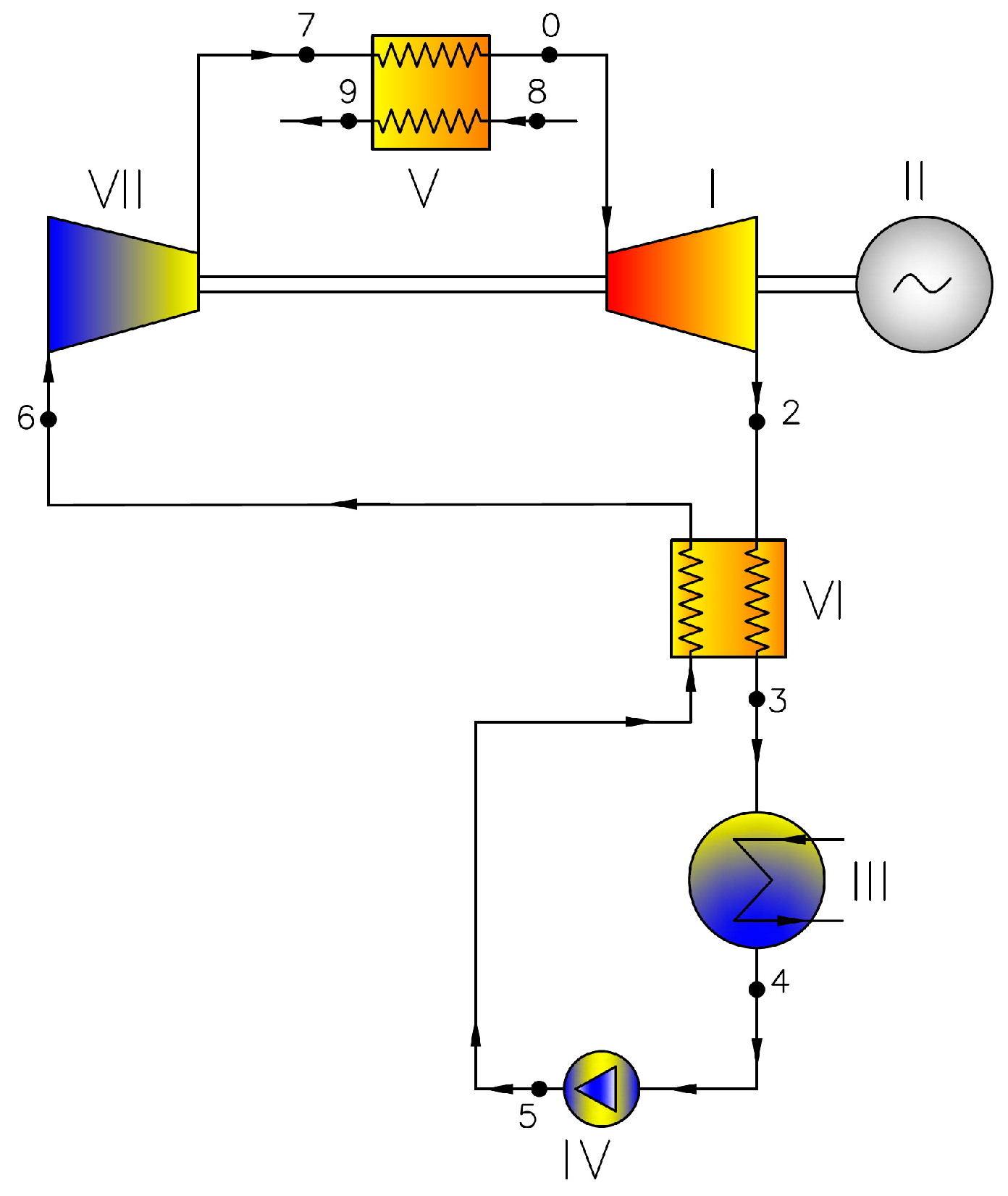
The schema of the simplest typical ORC cycle is presented in Figure 1. It consists of a turbine, an electric generator, a condenser (low temperature heat exchanger), a pump and a vapor generator (high temperature heat exchanger). If the expansion in the turbine ends in the zone of superheated vapor, an additional heat exchanger (so called “regenerator”) can be applied in order to use the heat of superheating for warming up the working liquid between the condenser and the boiler (Figure 2).
The analysis includes some other, more complex, schemas:
  • Cycle with saturated live steam and a regenerator for warming up the working fluid (Variant 1—Figure 2);
  • Cycle with superheated live steam and a regenerator for warming up the working fluid (Variant 2—Figure 2);
  • Cycle with superheated live steam and a regenerator for warming up, vaporization and partial superheating of the working fluid (Variant 3—Figure 2);
  • Cycle with supercritical live steam and a regenerator for warming up, vaporization and partial superheating of the working fluid (Variant 4—Figure 2);
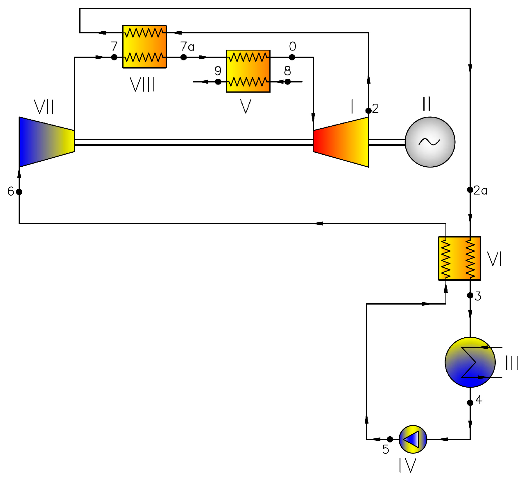
  • Cycle with superheated live steam, a regenerator for warming up, vaporization and partial superheating of the working fluid, and with a compressor (Variant 5—Figure 3);
  • Cycle with superheated live steam, a regenerator for warming up, vaporization and partial superheating of the working fluid, with a compressor and an additional heat exchanger (Variant 6—Figure 4);
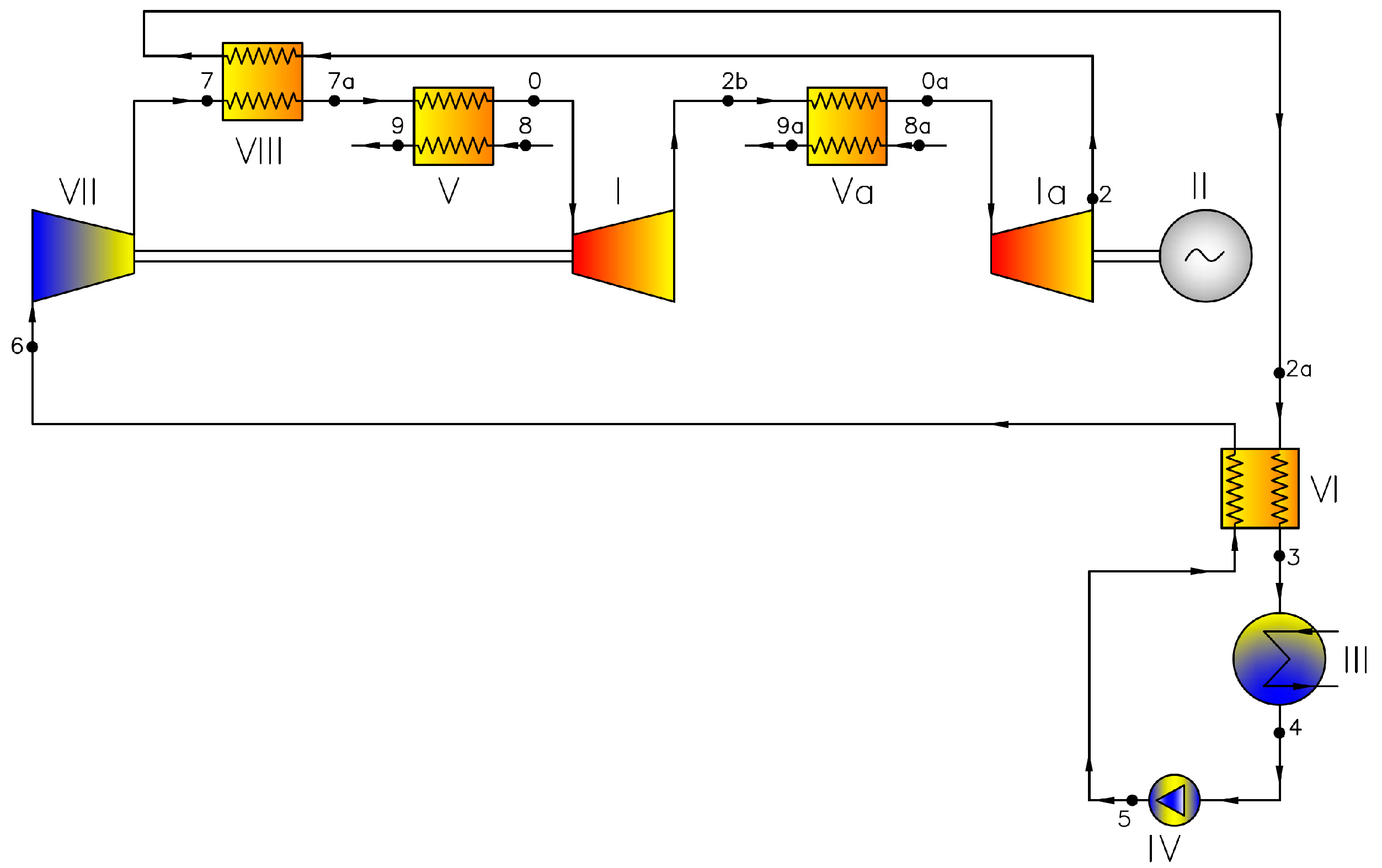
  • Cycle with superheated live steam, a regenerator for warming up, vaporization and partial superheating of the working fluid, with a compressor, an additional heat exchanger and interstage superheating (Variant 7—Figure 5);
  • Cycle with superheated live steam, a regenerator for warming up, vaporization and partial superheating of the working fluid, a compressor, an additional heat exchanger, interstage superheating and a vapor heater (Variant 8—Figure 6).
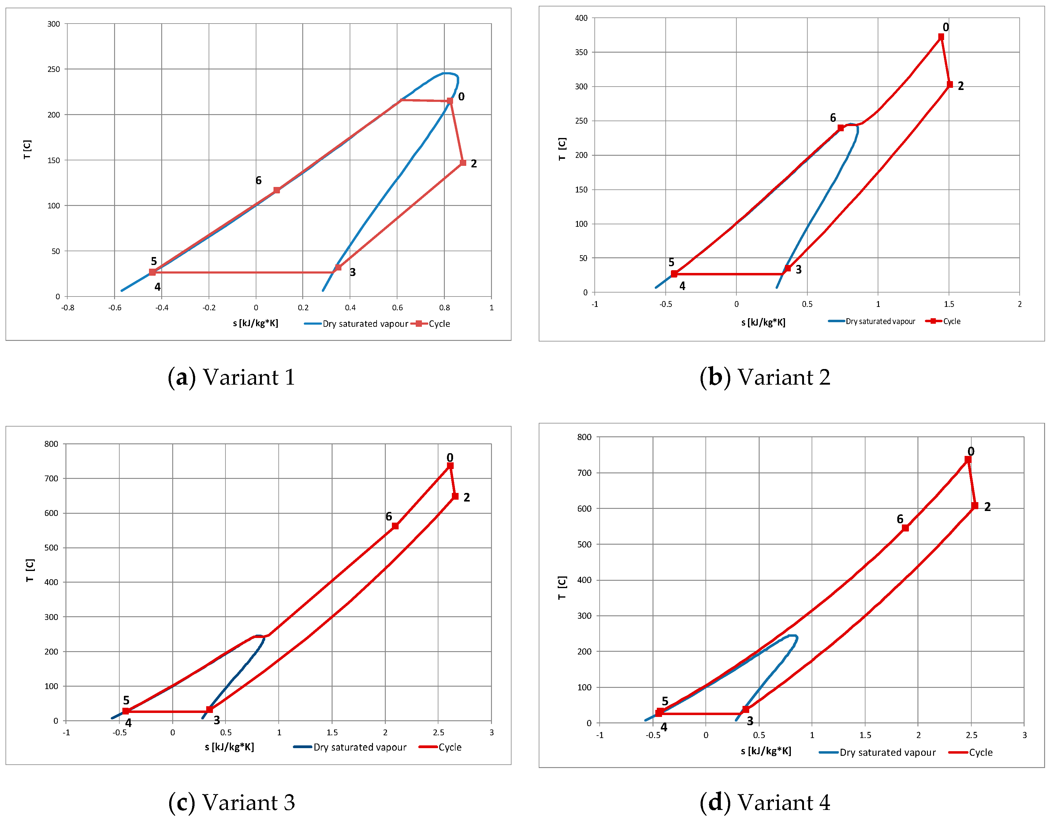
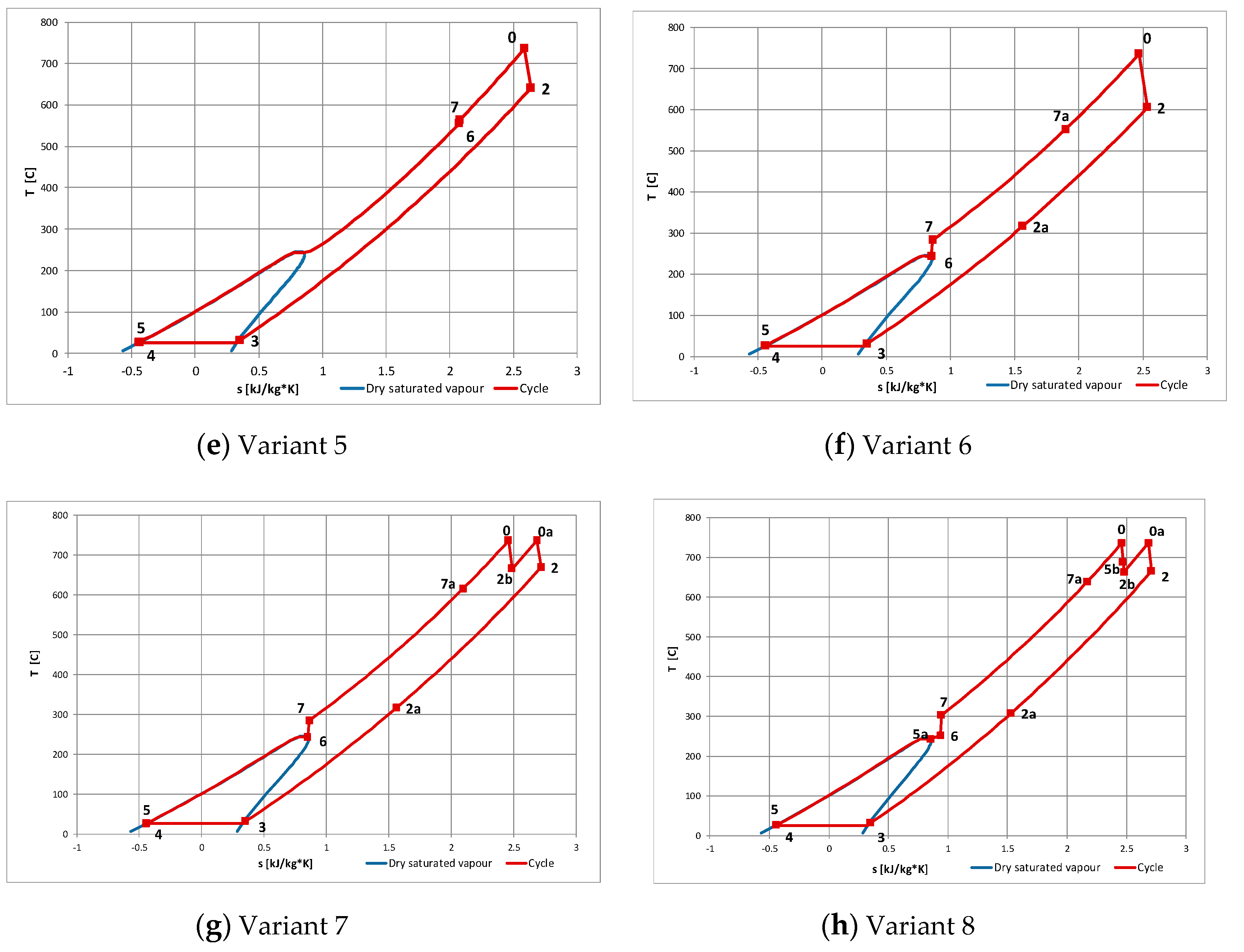
The interpretation of the above cycles in the temperature-entropy diagram is shown in Figure 7 with hexamethyldisiloxane (MM) as an example.
When choosing the working media, the most important features were taken into account, such as low toxicity, chemical stability, low potential for decomposition and low flammability [7]. The following media have been included in the analysis:
  • Acetone (chemical formula—C11H24, commercial name—acetone, [23]);
  • Octamethylcyclotetrasiloxane (chemical formula—C8H24O4Si4, commercial name—D4, [24]);
  • Dodecamethylcyclohexasiloxane (chemical formula—C12H36O6Si6, commercial name—D6, [24]);
  • Octamethyltrisiloxane (chemical formula—C8H24O2Si3, commercial name—MDM, [24]);
  • Hexamethyldisiloxane (chemical formula—C6H18OSi2, commercial name—MM, [24]);
  • 1,1,1,3,3-pentafluoropropane (chemical formula—C3H3F5, commercial name—R245fa, [24]);
  • 1,1,1,3,3-pentafluorobutane (chemical formula—C4H5F5, commercial name—R365mfc, [24]);
  • Methylcyclohexane (chemical formula—C7H14, commercial name—c1cc6, [24]);
  • N-propylcyclohexane (chemical formula—C9H18, commercial name—c3cc6, [24]);
  • Undecane (chemical formula—C11H24, commercial name—C11, [24]);
  • 1-chloro-3,3,3-trifluoroprop-1-ene (chemical formula—C3H2ClF3, commercial name—R1233zd, [25]).
The calculations have been performed assuming the schema of the thermodynamic cycle, the working medium and its upper and lower parameters. Standard thermodynamics formulae have been used, occasionally applying the iteration method. The parameters of the working media have been determined using REFPROP [26] media library. Unfortunately, there is no sufficient information concerning the chemical stability of most of the organic media. Thus, the maximum temperature for particular fluids have been assumed according to the data provided by REFPROP media library. The thermodynamic calculations have been carried out for 11 various fluids and 8 different cycles. The values of initial pressure and temperature have been determined taking into account particular schema of the cycle, media stability limitation and the maximum value of the cycle efficiency. The pressure in the condenser has been estimated assuming the temperature of the cooling water equal to 15 °C. The efficiencies of particular elements (typical of micro power plants) are shown in Table 1 [3,4,6,7,27].

2. Results and Discussion

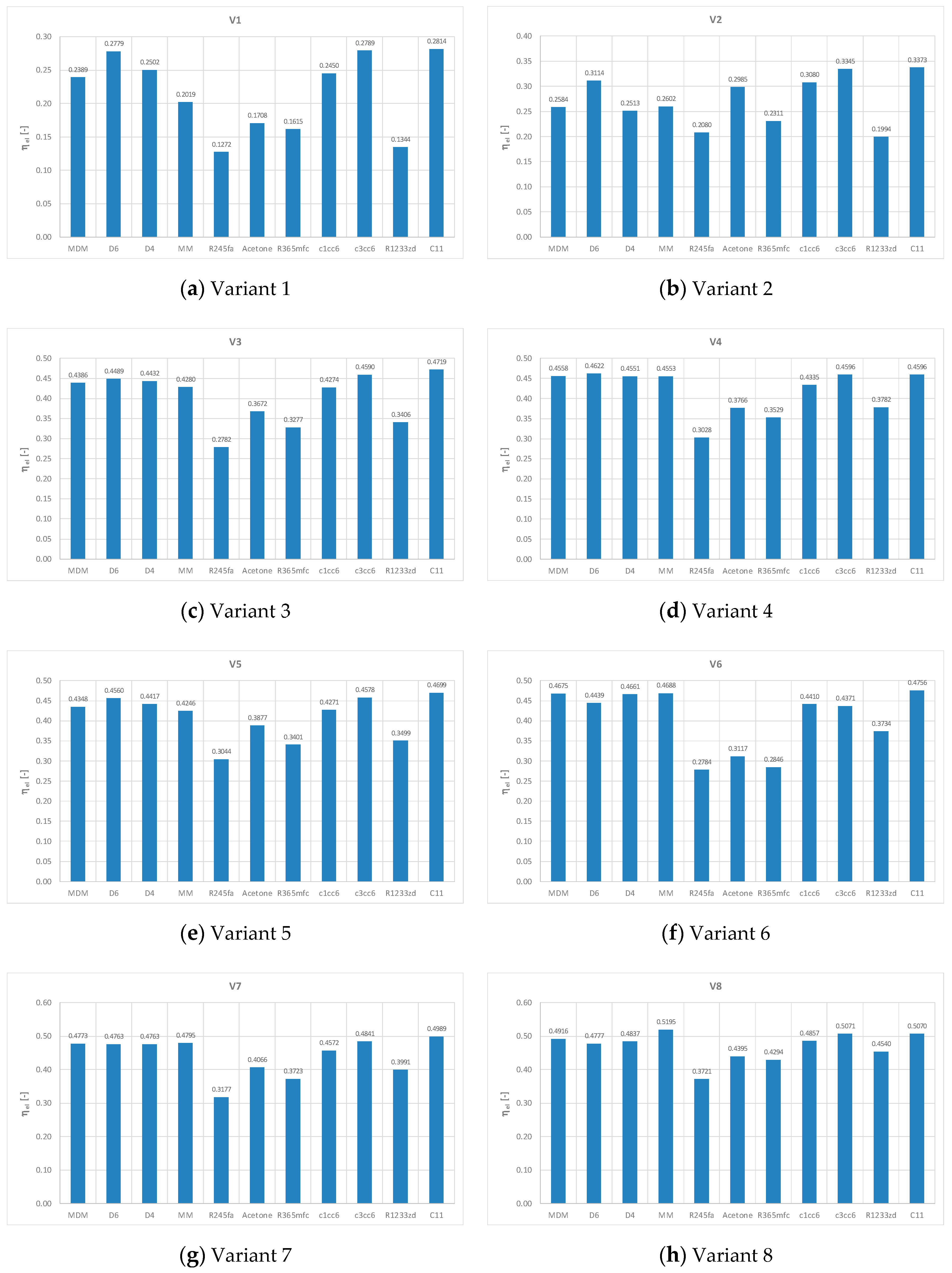
In the case of the simplest standard ORC cycle (Variant 1, Figure 2) the overall efficiency varies from 12% to 28% depending on the working medium and the parameters, Figure 8a.
For ORC cycle with superheated steam (Variant 2, Figure 2) higher values of efficiency can be obtained from 20% (R1233zd) to about 34% (C11), Figure 8b.
In Variant 3 (Figure 2)—the cycle with superheated live steam and the regenerator for warming up, vaporization and partial superheating of the working fluid the efficiencies vary from 28% (R245fa) to about 47% (C11), Figure 8c.
Variant 4 (Figure 2) is similar to Variant 3 except for the supercritical parameters at the turbine inlet allowing to obtain the efficiency from 30% (R245fa) to about 47% (D6)—Figure 8d.
In Variant 5 (Figure 3) the unusual element for ORC cycles appears: the compressor for vapor (Figure 3). The efficiencies of these plants vary from 30% (R245fa) to about 47% (C11)—Figure 8e.
In Variant 6 (Figure 4) the additional heat exchanger is applied and the efficiencies vary from 28% (R245fa) to above 47% (C11)—Figure 8f.
In Variant 7 (Figure 5) the interstage superheater is introduced and the efficiencies vary from 37% (R245fa) to nearly 50% (C11), Figure 8g.
Variant 8 (Figure 6) appears to be the most complex of the considered cycles (the heat exchanger with vapor bleeding from high pressure turbine (HP) is added). In this case the highest efficiencies ranging from 37% (R245fa) to nearly 52% (MM) may be obtained—Figure 8h.
The numbers in the Figure 7 refer to the characteristic cycle points shown in Figure 2, Figure 3, Figure 4, Figure 5 and Figure 6, respectively.
In particular variants of the power plants and the applied working fluids the values of the upper temperature and pressure vary remarkably. For example, the temperature and pressure of live vapor in Variant 1 are presented in Figure 9. The temperature changes from 145 °C (R245fa) to 372 °C (D6), while the pressure from 0.95 MPa (D6) to about 3.5 MPa (acetone). In Variant 8 the temperatures and pressure are shown in Figure 10. The temperature changes from 380 °C (R245fa) to 770 °C (C11), while the pressure from 9.59 MPa (D4) to about 22.14 MPa (acetone).
As far as the interstage superheater is considered, the pressure varies even more remarkably, Figure 11. In Variant 8, for example, it changes from 0.012 MPa (D6) to 1.55 MPa (R245fa).
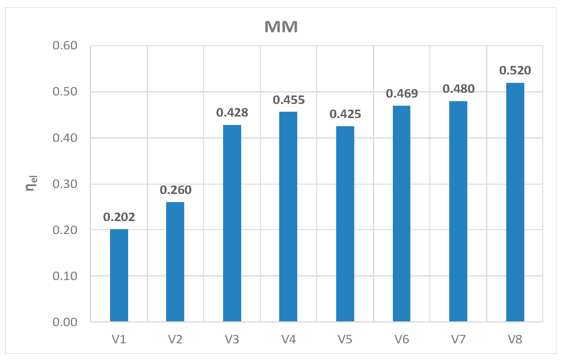
Thus, comparing the efficiencies of various considered cycles the values of upper temperatures should be taken into account. Very high overall efficiency (52%) was achieved for the MM medium in Variant 8 (Figure 12).
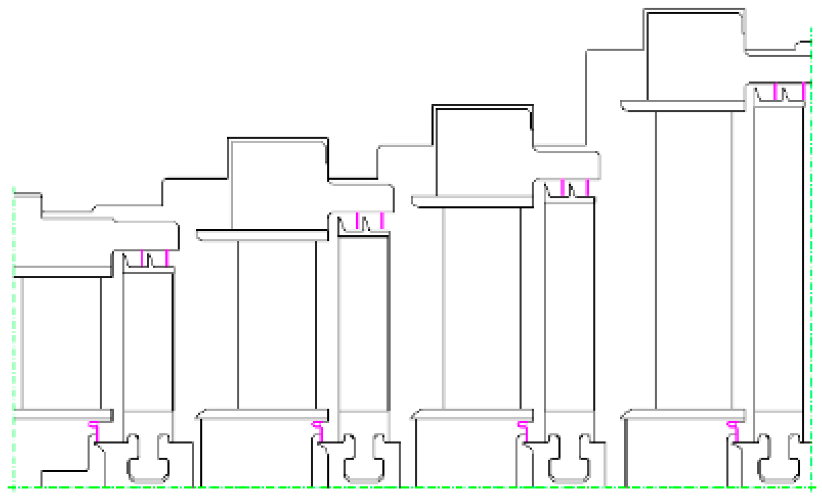
The examples of turbine flow parts in Variants 1, 6 and 8 are presented in Figure 13, Figure 14 and Figure 15. All the examples can be treated as micro turbines (turbines of very small output) with vapor of MM as the working medium. The variants have been designed as multistage turbines with disc rotors (impulse turbines). In Figure 13 a 4-stage turbine of 75 kW is shown and in Figure 14 a flow part of the 8-stage turbine of 240 kW is presented. While Figure 15 shows flow parts of 5-stage high pressure (HP) turbine and of 3-stage low pressure (LP) turbine of total output equal 220 kW.

3. Conclusions

Nowadays, only very simple ORC cycles are applied and described in bibliography (Figure 1 and Figure 2). They are limited to 4 or 5 main elements: the turbine, the condenser, the pump, the vapor generator and the regenerator. The temperature of live vapor in these solutions is relatively low (lower than 300 °C). The presented analyses have been performed for far more complex cycles, for higher values of temperature (even 700 °C) and for higher values of the initial pressure. New elements, such as additional heat exchangers, interstage superheaters and compressors have been included in the cycles. These types of ORC power plants have not been discussed in bibliography so far. The obtained results of the presented analysis can be considered for future applications.
The performed analyses clearly prove that it is possible to build ORC power plants of relatively high efficiency even exceeding that of 50%, which is a very competitive value. In such cases ORC power plants can achieve an efficiency which is higher than that of modern steam turbine plants with supercritical parameters. The statement seems to stand in contradiction with the opinion that above 350 °C steam power plants have a higher efficiency than power plants with organic media. It is also very important to underline that even the most complex cycle (Variant 8 with MM working fluid) is cheaper and much simpler than modern supercritical steam power plants of large output with similar maximum efficiency.

Author Contributions

Conceptualization, K.K. and M.P.; methodology, K.K. and M.P.; formal analysis K.K. and M.P.; data curation, K.K. and M.P.; writing—original draft preparation, K.K. and M.P.; writing—review and editing, K.K. and M.P.; supervision, K.K. and M.P.; funding acquisition, K.K. and M.P. All authors have read and agreed to the published version of the manuscript.

Funding

This research received no external funding.

Conflicts of Interest

The authors declare no conflict of interest. The funders had no role in the design of the study; in the collection, analyses, or interpretation of data; in the writing of the manuscript, and in the decision to publish the results.

References

  1. Kamiński, J.; Kudełko, M. The prospects for hard coal as a fuel for the Polish power sector. Energy Policy 2010, 38, 7939–7950. [Google Scholar] [CrossRef]
  2. Szczerbowski, R.; Ceran, B. Development perspectives of the Polish power generation sector according to the climate preservation conference COP21 policies. E3S Web Conf. 2017, 14, 1–10. [Google Scholar] [CrossRef] [Green Version]
  3. Kosowski, K.; Tucki, K.; Piwowarski, M.; Stepien, R.; Orynycz, O.; Wlodarski, W. Thermodynamic Cycle Concepts for High-Efficiency Power Plants. Part B: Prosumer and Distributed Power Industry. Sustainability 2019, 11, 2647. [Google Scholar] [CrossRef] [Green Version]
  4. Mikielewicz, D.; Kosowski, K.; Tucki, K.; Piwowarski, M.; Stępień, R.; Orynycz, O.; Włodarski, W. Influence of Different Biofuels on the Efficiency of Gas Turbine Cycles for Prosumer and Distributed Energy Power Plants. Energies 2019, 12, 3173. [Google Scholar] [CrossRef] [Green Version]
  5. Kosowski, K.; Piwowarski, M.; Stepien, R.; Włodarski, W. Performance characteristics of a micro-turbine. J. Vib. Eng. Technol. 2014, 2, 341–350. [Google Scholar]
  6. Kosowski, K.; Piwowarski, M.; Stepien, R.; Włodarski, W. Design and investigations of the ethanol microturbine. Arch. Thermodyn. 2018, 39, 41–54. [Google Scholar] [CrossRef]
  7. Landelle, A.; Tauveron, N.; Haberschill, P.; Revellin, R.; Colasson, S. Organic Rankine cycle design and performance comparison based on experimental database. Appl. Energy 2017, 204, 1172–1187. [Google Scholar] [CrossRef]
  8. Quoilin, S.; Lemort, V. Technological and Economical Survey of Organic Rankine Cycle Systems. In Proceedings of the 5-th European Conference Economics and Management of Energy in Industry, Villamura, Portugal, 14–17 April 2009. [Google Scholar]
  9. Piwowarski, M. Optimization of steam cycles with respect to supercritical parameters. Pol. Marit. Res. 2009, S1, 45–51. [Google Scholar] [CrossRef] [Green Version]
  10. Tumanovskii, A.G.; Shvarts, A.L.; Somova, E.V.; Verbovetskii, E.Kh.; Avrutskii, G.D.; Ermakova, S.V.; Kalugin, R.N.; Lazarev, M.V. Review of the Coal-Fired, Over-Supercritical and Ultra-Supercritical Steam Power Plants, Pleiades Publishing. Therm. Eng. 2017, 64, 83–96. [Google Scholar] [CrossRef]
  11. Piwowarski, M.; Kosowski, K. Design analysis of combined gas-vapour micro power plant with 30 kW air turbine. Pol. J. Environ. Stud. 2014, 23, 1397–1401. [Google Scholar]
  12. Włodarski, W. Experimental investigations and simulations of the microturbine unit with permanent magnet generator. Energy 2018, 158, 59–71. [Google Scholar] [CrossRef]
  13. Włodarski, W. Control of a vapour microturbine set in cogeneration applications. ISA Trans. 2019. [Google Scholar] [CrossRef] [PubMed]
  14. Włodarski, W. A model development and experimental verification for a vapour microturbine with a permanent magnet synchronous generator. Appl. Energy 2019, 252. [Google Scholar] [CrossRef]
  15. Kosowski, K.; Stępień, R.; Włodarski, W.; Piwowarski, M.; Hirt, Ł. Partial admission stages of high efficiency for a microturbine. J. Vib. Eng. Technol. 2014, 2, 441–448. [Google Scholar]
  16. Braimakis, K.; Karellas, S. Energetic optimization of regenerative Organic Rankine Cycle (ORC) configurations. Energy Convers. Manag. 2018, 159, 353–370. [Google Scholar] [CrossRef]
  17. Duvia, A.; Gaia, M. ORC Plants for Power Production from Biomas from 0.4MWe to 1.5MWe: Technology, Efficiency, Practical Experiences and Economy. In Proceedings of the 7th Holzenergie Symopsium, Zurich, Switzerland, 18 October 2002. [Google Scholar]
  18. Duvia, A.; Tavolo, S. Application of ORC Units in the Pellet Production, Field: Technical-Economic Considerations and Overview of the Operational Results of an ORC Plant in the Industry Installed in Mudau (Germany). In Proceedings of the 7th Holzenergie Symopsium, Zurich, Switzerland, 18 October 2002. [Google Scholar]
  19. Kosowski, K.; Tucki, K.; Piwowarski, M.; Stępień, R.; Orynycz, O.; Włodarski, W.; Bączyk, A. Thermodynamic Cycle Concepts for High-Efficiency Power Plans. Part A: Public Power Plants 60+. Sustainability 2019, 11, 554. [Google Scholar] [CrossRef] [Green Version]
  20. Mikielewicz, D.; Kosowski, K.; Tucki, K.; Piwowarski, M.; Stępień, R.; Orynycz, O.; Włodarski, W. Gas Turbine Cycle with External Combustion Chamber for Prosumer and Distributed Energy Systems. Energies 2019, 12, 3501. [Google Scholar] [CrossRef] [Green Version]
  21. Mikielewicz, D.; Mikielewicz, J. Cogenerative micro power plants—A new direction for development of power engineering? Arch. Thermodyn. 2008, 29, 109–132. [Google Scholar]
  22. Mikielewicz, J.; Mikielewicz, D. Comparative study of selected fluids for use in supercritical Organic Rankine Cycles. Arch. Thermodyn. 2009, 30, 3–15. [Google Scholar]
  23. Set of Product’s Card of Chempur Poland Ltd. Available online: http://en.chempur.pl (accessed on 25 February 2020).
  24. Set of Product’s Card of Sigma-Aldrich Ltd. Available online: https://www.sigmaaldrich.com (accessed on 25 February 2020).
  25. Set of Product’s Card of SCHIESSL Poland Ltd. Available online: https://www.schiessl.pl/en (accessed on 25 February 2020).
  26. Lemmon, E.; Huber, M.; McLinden, M. NIST Standard Reference Database 23: Reference Fluid Thermodynamic and Transport Properties-REFPROP, 9th ed.; National Institute of Standards and Technology, Standard Reference Data Program: Gaithersburg, MD, USA, 2010. [Google Scholar]
  27. Wajs, J.; Mikielewicz, D.; Jakubowska, B. Performance of the domestic micro ORC equipped with the shell-and-tube condenser with minichannels. Energy 2018, 157, 853–861. [Google Scholar] [CrossRef]
Figure 1. Standard Organic Rankine Cycle (ORC) cycle for wet fluids; where: I—turbine, II—generator, III—condenser, IV—main pump, V—vapor generator.
Energies 13 01327 g001
Figure 2. ORC cycle with regenerator; where: I—turbine, II—generator, III—condenser, IV—pump, V—vapor generator, VI—regenerator (Variant 1, 2, 3, and 4).
Energies 13 01327 g002
Figure 3. ORC cycle with regenerator and compressor; where: I—turbine, II—generator, III—condenser, IV—pump, V—vapor generator, VI—regenerator, VII—compressor (Variant 5).
Energies 13 01327 g003
Figure 4. ORC cycle with regenerator, compressor and reheater; where: I—turbine, II—generator, III—condenser, IV—pump, V—vapor generator, VI—regenerator, VII—compressor, VIII—heat exchanger (Variant 6).
Energies 13 01327 g004
Figure 5. ORC cycle with regenerator, compressor, reheater and interstage superheater; where: Ia, Ib—turbines, II—generator, III—condenser, IV-pump, V—vapor generators, Va—interstage superheater, VI—regenerator, VII—compressor, VIII—heat exchanger (Variant 7).
Energies 13 01327 g005
Figure 6. ORC cycle with regenerator, compressor, reheater, interstages superheater and heat exchanger; where: Ia, Ib—turbines, II—generator, III—condenser, IV, IVa—pumps, V—vapor generators, Va—interstage superheater, VI—regenerator, VII—compressor, VIII—heat exchanger, IX—vapor heater (Variant 8).
Energies 13 01327 g006
Figure 7. Cycle interpretation in T-s diagram for all analyzed variants (hexamethyldisiloxane (MM) working fluid). The numbers in the graphs refer to the characteristic cycle points shown in Figure 2, Figure 3, Figure 4, Figure 5 and Figure 6: (a) Variant 1-Figure 2; (b) Variant 2-Figure 2; (c) Variant 3-Figure 2; (d) Variant 4-Figure 2; (e) Variant 5-Figure 3; (f) Variant 6-Figure 4; (g) Variant 7-Figure 5; (h) Variant 8-Figure 6.
Energies 13 01327 g007aEnergies 13 01327 g007b
Figure 8. Overall efficiency for different working media: (a) Variant 1; (b) Variant 2; (c) Variant 3; (d) Variant 4; (e) Variant 5; (f) Variant 6; (g) Variant 7; (h) Variant 8.
Energies 13 01327 g008
Figure 9. Values of temperature (a) and pressure (b) of live vapor optimized for different working media (Variant 1).
Energies 13 01327 g009
Figure 10. Values of temperature (a) and pressure (b) of live vapor optimized for different working media (Variant 8).
Energies 13 01327 g010
Figure 11. Variant 8—pressure of interstage superheater.
Energies 13 01327 g011
Figure 12. Maximum overall efficiency in particular variants of power plants (MM working fluid).
Energies 13 01327 g012
Figure 13. Turbine flow part for Variant 1 and MM working fluid.
Energies 13 01327 g013
Figure 14. Turbine flow part for Variant 6 and MM working fluid.
Energies 13 01327 g014
Figure 15. Flow part of high (a) and low pressure (b) turbine for Variant 8 and MM working fluid.
Energies 13 01327 g015
Table 1. Assumed values of the efficiencies of particular cycle elements.
DescriptionSymbolValueUnit
Turbine efficiencyηT0.85[-]
Compressor efficiencyηcom0.85[-]
Pump efficiencyηPG0.80[-]
Mechanical efficiencyηm0.98[-]
Leakage efficiencyηn0.98[-]
Generator efficiencyηG0.90[-]
Regenerator efficiencyηR0.95[-]
Pressure drop in heaters and regeneratorspi/pi-10.98[-]