Article

Starting Pulse Vibration Torque Analysis of Aviation Variable Frequency Asynchronous Motor Based on Low-Frequency Step-Down Starting Methods

1
School of Automation Science and Electrical Engineering, Beihang University, Beijing 100191, China
2
Engineering Training Center, Beihang University, Beijing 100191, China
*
Author to whom correspondence should be addressed.
Energies 2020, 13(6), 1337; https://doi.org/10.3390/en13061337
Submission received: 14 February 2020 / Revised: 6 March 2020 / Accepted: 9 March 2020 / Published: 13 March 2020
(This article belongs to the Section F: Electrical Engineering)

Abstract

:
The more electric aircraft provides 115 V/360~800 Hz variable frequency power supply for the variable frequency asynchronous motor, and the motor operation characteristics change with the power frequency variation. It causes the starting pulse vibration torque with the low-frequency power supply (360 Hz) to increase greatly and the mechanical shock and fatigue damage. Therefore, this paper proposes step-down starting method with the low-frequency power supply. Based on the electromagnetic principles generated by the starting pulse vibration torque, this paper uses a novel method of simulation data fitting to establish an approximate model of the starting pulse vibration torque. The parameter design formulas of the low-frequency step-down starting methods, including the reducing voltage, the series resistance, and the series inductance are proposed. The effectiveness of the different methods are verified, and the performance is compared through the simulation. The experimental verification of a small power asynchronous motor is completed. The simulation and experiment results show that the low-frequency step-down starting methods effectively reduce the starting peak torque, and also suppress the shock impact of starting current on the power supply.

1. Introduction

Regarding the asynchronous motor starting characteristic, the research and analysis contents pay more attention to issues such as the large starting current and the small starting torque [1,2]. In addition, when the asynchronous motor starts, there is the starting pulse vibration torque. It is transmitted to the mechanical system through the coupling of multiple physical domains and brings adverse effects for the mechanical system. The ref [3,4] mainly indicate that the starting pulse vibration torque effect of 50 Hz constant frequency asynchronous motor is transmitted to the mechanical system through the couplings of multiple physical domains, which leads to the bearing resonance and fracture. The ref [5] similarly describes that the impact of starting pulse vibration torque is transmitted to the mechanical system, which eventually damages and breaks the gearbox. Therefore, the starting pulse vibration torque brings the large damage to the mechanical system, which is the problem that cannot be ignored.
For the starting pulse vibration torque impact of asynchronous motors on the mechanical system, the mechanical system design is generally improved, and the mechanical system strength is increased to prevent the damage. The ref [6,7] reduce the starting pulse vibration torque by changing the motor structure, such as groove shape or the mechanical bearing stiffness. The ref [8] proposes a method by reducing the starting voltage to decrease the starting pulse vibration pulse. However, this method further reduces the starting torque as the starting pulse vibration torque decreases and can only be applied to drive systems with no-load and light-load starting.
The variable frequency power supply system of 115 V/360~800 Hz is applied by the more electric aircraft [9,10,11,12]. Compared with constant frequency power supply, the performance of equipment and system should adapt to this change [13,14,15,16]. For the asynchronous motor powered by the variable frequency power supply, the operation characteristics change with the power frequency variation. The ref [17,18] shows that the starting torque, the critical torque, the starting current, and the starting pulse vibration torque will decrease as the power frequency increases. Therefore, the starting pulse vibration of aviation variable frequency asynchronous motors is very large at a low-frequency (360 Hz) power supply, and the impact on the mechanical system is more serious [19]. It directly affects the reliability, fatigue, and life of mechanical system [20,21]. The higher requirement is proposed for the mechanical system design.
In order to solve the problem of mechanical shock, it is necessary to analyze the formation principle of starting pulse vibration torque. The ref [22] analyses the electromagnetic principle of the starting pulse vibration torque, and it is a complex coupling process formed by the interaction of different magnetic fields between the stator and rotor. However, it is only qualitative analysis and the related parameter derivation is not given. For the complex coupling problem, the ref [23] simplifies the complex mechanical transmission models, such as the gears and bearings from high-order to low-order, which is convenient for analyzing the coupling and resonance form the electrical system of the more electric aircraft to the mechanical system. Therefore, based on the simplified analysis method, a novel approximate modeling method by the data fitting for the peak torque generated by the pulse vibration torque is proposed and provides the basic evidence for the step-down starting design method.
For the asynchronous motor powered by the variable frequency power supply, it has a large margin of the starting torque and the critical torque with the low-frequency power supply. This paper proposes a control method of low-frequency step-down starting to reduce the starting pulse vibration torque with the low-frequency power. The power supply frequency range can be divided into two parts. In the low-frequency band, the voltage reduction, the series resistance, or the series inductance are used to perform the power supply step-down starting. In the high-frequency range, the method of rated power supply voltage starting is used. Based on the electromagnetic principle of starting pulse vibration torque, the paper establishes a mathematical model of the starting pulse vibration torque through the method of simulation data fitting, and proposes that the minimum peak torque caused by the starting pulse vibration torque is applied as the design goal. It also derives the parameter calculation formulas of the low-frequency step-down starting, including the voltage reduction, the series resistance, and the series inductance. Finally, the method feasibility is verified by simulation and experiments.

2. Torque Characteristics of Aviation Variable Frequency Asynchronous Motor

2.1. Mechanical Characteristics of Variable Frequency Asynchronous Motor

When the asynchronous motor is supplied by the aviation variable frequency power supply, the synchronous speed changes by the influence of power supply frequency, which causes the mechanical characteristic change. Figure 1 shows the mechanical characteristics of four-pole asynchronous motor with the aviation variable frequency power supply.
As seen from the mechanical characteristics of Figure 1, both the critical torque and the starting torque decrease with the increase of power supply frequency. It can be approximated as:
T s t = 3 p U 1 2 R 2 2 π f 1 [ ( R 1 + R 2 ) 2 + 4 π 2 f 1 2 ( L l 1 + L l 2 ) 2 ] 3 p U 1 2 R 2 8 π 3 f 1 3 ( L l 1 + L l 2 ) 2
T e m = 3 p U 1 2 4 π f 1 [ R 1 + R 1 2 + 4 π 2 f 1 2 ( L l 1 + L l 2 ) 2 ] 3 p U 1 2 8 π 2 f 1 2 ( L l 1 + L l 2 )
where, Tst is the starting torque, Tem is the critical torque, p is the number of pole pairs, U1 is the power supply voltage, f1 is the power supply frequency, R1 is the stator resistance, Ll1 is the stator leakage inductance, R’2 is the rotor resistance, and L’l2 is the rotor leakage inductance. The critical torque is the approximately square descent as the power supply frequency rises, and the starting torque is the approximately cubic descent as the power supply frequency rises. Therefore, in the design of variable frequency asynchronous motor, it is necessary to provide an index of starting torque Tst and the critical torque Tem with the high-frequency power supply (f1 = f1H = 800 Hz). Generally expressed by the starting torque coefficient kst and the critical torque coefficient km, they are respectively defined as:
k s t = T s t H T n H , k m = T e m H T n H
where, TnH is the working torque with f1H, TstH is the starting torque with f1H, and TemH is the critical torque with f1H. According to the characteristics of Equations (1) and (2), it can be known that the realization conditions of kst in the Equation (3) are more rigorous than km. In the motor design, the motor starting with the loads needs to meet kst, and the motor starting with the light loads only needs to meet km.

2.2. Starting Pulse Vibration Torque of Variable Frequency Asynchronous Motor

In the mechanical design of asynchronous motors, it is necessary to analyze the maximum torque Tmax of shaft during the operation, and the Tmax generally appears as the asynchronous motor starts. It may be the critical torque Tem or the peak torque caused by the starting pulse vibration torque, which is defined by the Tstm.
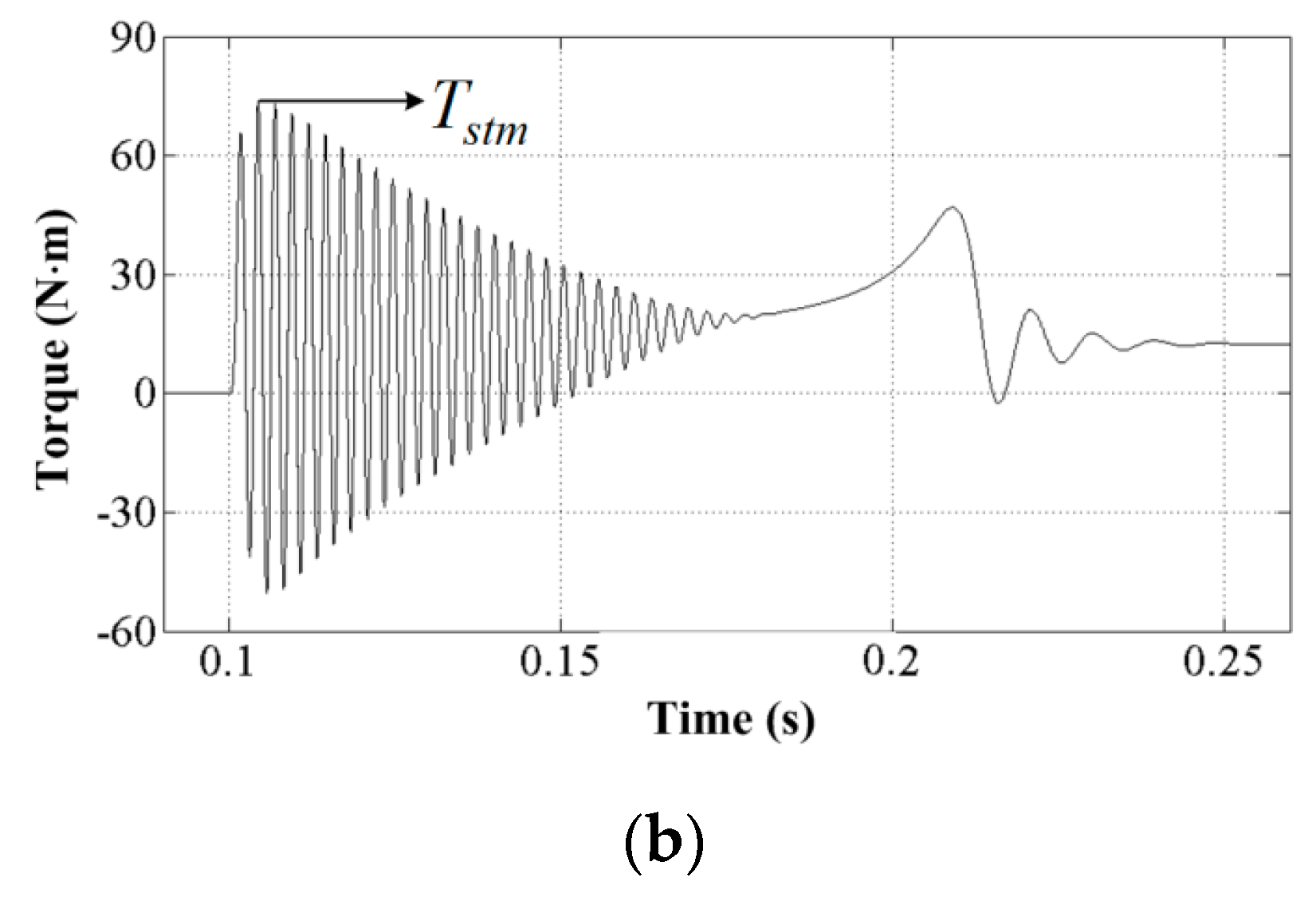
For the asynchronous motor with the traditional constant frequency power supply, the Tstm is usually less than the Tem. The starting process of 400 Hz aviation constant frequency asynchronous motor is shown in Figure 2a. Even if Tstm is larger than the Tem, it is only necessary to appropriately increase the design safety factor, and the starting pulse vibration torque influence may not be considered. However, for meeting the mechanical characteristic requirement with the power supply frequency change, such as the Formula (3), the Tmax caused by the motor design parameters during the starting is no longer the Tem, for the asynchronous motor with the variable frequency asynchronous motor. The Tmax is the Tstm caused by the starting pulse vibration torque, as shown in Figure 2b.
The relationship between the Tstm caused by the starting pulse vibration torque and the power supply frequency f1 during the variable frequency asynchronous motor starting is shown in Figure 2c. It can be seen that the Tstm is already larger than the Tem with the f1H = 800 Hz, and the Tstm is significantly larger than the Tem with the f1L = 360 Hz. Obviously, the Tmax of mechanical shaft formed by the Tstm with the low-frequency power supply is very large, which has a great effect on the fatigue strength of mechanical shaft.

3. Starting Pulse Vibration Torque Model

The principle of starting pulse vibration torque of asynchronous motor is that the stator and rotor magnetic fields cannot be synchronized immediately, forming electromagnetic pulse vibration torque, due to the transient process existence in the stator and rotor circuits during the starting.

3.1. Transient Characteristics of Starting Current and Torque

The voltage balance formula of asynchronous motor in the α-β two-phase stationary coordinate system is:
[ u α 1 u β 1 0 0 ] = [ R 1 + L s p 0 L m p 0 0 R 1 + L s p 0 L m p L m p ω L m R 2 + L r p ω L r ω L m L m p ω L r R 2 + L r p ] [ i α 1 i β 1 i α 2 i β 2 ]
where, R1 and R2 are the stator and rotor resistances, respectively, Ls and Lr are the stator and rotor winding self-inductances, respectively, and Lm is the mutual inductance between the stator and rotor windings.
The stator and rotor current expressions can be obtained as:
[ i α 1 i β 1 ] = 1 / R 1 ( 1 + T 1 p ) { [ u α u β ] L m p [ i α 2 i β 2 ] }
[ i α 2 i β 2 ] = L m L r { [ 1 1 ] [ W 11 ( p ) W 12 ( p ) W 21 ( p ) W 22 ( p ) ] } [ i α 1 i β 1 ]
The transfer function in the Equation (6) is:
W 11 ( s ) = W 22 ( s ) = T 2 p + 1 T 2 2 p 2 + 2 T 2 p + 1 + T 2 2 ω 2 W 12 ( s ) = W 21 ( s ) = T 2 ω T 2 2 p 2 + 2 T 2 p + 1 + T 2 2 ω 2
In the Formulas (5) and (7), T1 and T2 can be expressed as T1 = Ls/R1 and T2 = Lr/R2.
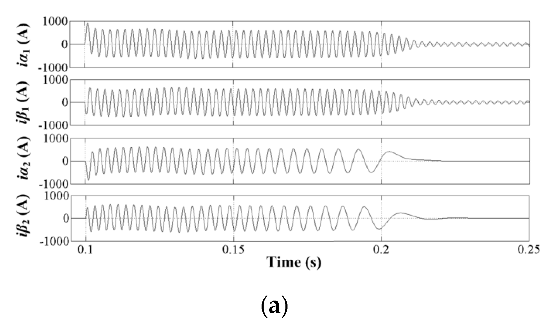
Figure 3a is the current waveform caused by the transient process of Equations (5)–(7). The stator currents i α 1 , i β 1 are the AC current with the frequency f1 superimposed on the DC current transient process, and the rotor currents i α 2 , i β 2 are AC current with the slip frequency fs superimposed on the DC current transient process.
Since the stator and rotor currents exist in the DC transient process, the starting torque includes the pulse vibration torque shown in Figure 3b, which can be expressed as:
T s t = p L m ( i α 2 i β 1 i α 1 i β 2 ) = T ¯ s t + T ˜ s t
It consists of average torque T ¯ s t and the pulse vibration torque T ˜ s t during the starting operation.
The peak torque caused by pulse vibration torque is:
T s t m = max [ p L m ( i α 2 i β 1 i α 1 i β 2 ) ] = max ( T ¯ s t + T ˜ s t )

3.2. Basic Principle of Starting Torque

Obviously, the cause of pulse vibration torque is that the power is suddenly applied to the stator and rotor windings generates the transient currents containing the AC and DC components [22]. If it is expressed as:
i α 1 = i ˜ α 1 + i ¯ α 10 i β 1 = i ˜ β 1 + i ¯ β 10 i α 2 = i ˜ α 2 + i ¯ α 20 i β 2 = i ˜ β 2 + i ¯ β 20
These currents generate the magnetic potential in the motor air gap, as shown in Figure 4.
(1)
Fss: the rotating magnetic potential on the stator with the synchronous speed (ω1) generated by the stator currents i ˜ α 1 , i ˜ β 1 of frequency f1.
(2)
F0s: the static magnetic potential on the stator with the speed of zero caused by the DC component of stator currents i ¯ α 10 , i ¯ β 10 .
(3)
F0r: the rotating magnetic potential on the rotor with the synchronous speed (ωm) generated by the DC component of rotor currents i ¯ α 20 , i ¯ β 20 .
(4)
Fsr: the rotating magnetic potential on the rotor with the synchronous speed (ω1 = ωs + ωm) generated by the rotor current i ¯ α 2 , i ¯ β 2 of frequency fs.
The four kinds of magnetic potentials interact to generate the electromagnetic torque shown in Figure 3b. The Fss and Fsr interact to produce the average electromagnetic torque T ¯ s t in Equation (8), the F0r and Fsr with the f1 interact to produce the pulse vibration torque T ˜ s t , the Fss and F0r with the fs interact to produce the pulse vibration torque T ˜ s t 2 , and the F0s and F0r with the fm interact to produce the pulse vibration torque T ˜ s t 3 , which is the relatively complicated transient process.
Obviously, if the analytical formula of pulse vibration torque is derived according to Formulas (5)–(8), it will be very complicated and inconvenient for the engineering design and application.

3.3. Approximate Model of Starting Peak Torque

For the research on the starting pulse vibration torque, it analyzes the Tmax of motor design, that is, the torque shock of mechanical device caused by the starting pulse vibration torque. Therefore, the starting peak torque Tstm is taken as the research target, which requires a model that can express the law of Tstm and is convenient for the engineering design and application.
For the torque characteristic of Equation (8) from t = 0 to Δt, the T ˜ s t generated by the interaction between Fss and Fsr is usually described by the Formula (1) at the t = 0, and the starting current Ist can be expressed as:
I s t = U 1 ( R 1 + R 2 ) 2 + 4 π 2 f 1 2 ( L l 1 + L l 2 ) 2
T ¯ s t = 3 p n U 1 2 R 2 2 π f 1 [ ( R 1 + R 2 ) 2 + 4 π 2 f 1 2 ( L l 1 + L l 2 ) 2 ] = 3 p n R 2 2 π f 1 I s t 2 = C ¯ s t I s t 2
where, the stator current and rotor current are approximately equal during the starting. They are proportional to the power supply voltage U1, and the starting torque T ¯ s t is proportional to the starting current I s t 2 .
For the T ˜ s t , the same method is applied. Since Tstm only appears at the motor starting moment, the magnitude of DC component i ¯ α 10 , i ¯ β 10 , i ¯ α 20 , i ¯ β 20 should be determined by the U1 suddenly applied to the windings. It is close to the initial value of transition process, which is approximately proportional to U1. It can be seen that the F0s and F0r magnitudes are approximately proportional to U1. According to the Formula (11), it can also be approximately proportional to Ist. If the magnetic potential phase effect is ignored, the T ˜ s t can also be assumed to be proportional to I s t 2 , the Tstm with the different f1 is approximately assumed to be:
T s t m C s t m I s t 2 = C s t m U 1 2 ( R 1 + R 2 ) 2 + 4 π 2 f 1 2 ( L l 1 + L l 2 ) 2
According to Formula (12), when 360~800 Hz aviation power supply is applied, the coefficient C ¯ s t is inversely proportional to the power frequency f1. However, the motor operates in magnetic saturation state with the low frequency, and in weak magnetic state with the high frequency. The relationship between C ¯ s t and f1 is complex and nonlinear. The nonlinear relationship between the coefficient Ctms of Formula (13) and is more complicated.
The 7.5 kW variable frequency asynchronous motor is taken as an example, the approximate law of Tstm is analyzed by the simulation to verify the feasibility of Formula (13). The parameters of aviation variable frequency asynchronous motor are shown in Table 1.
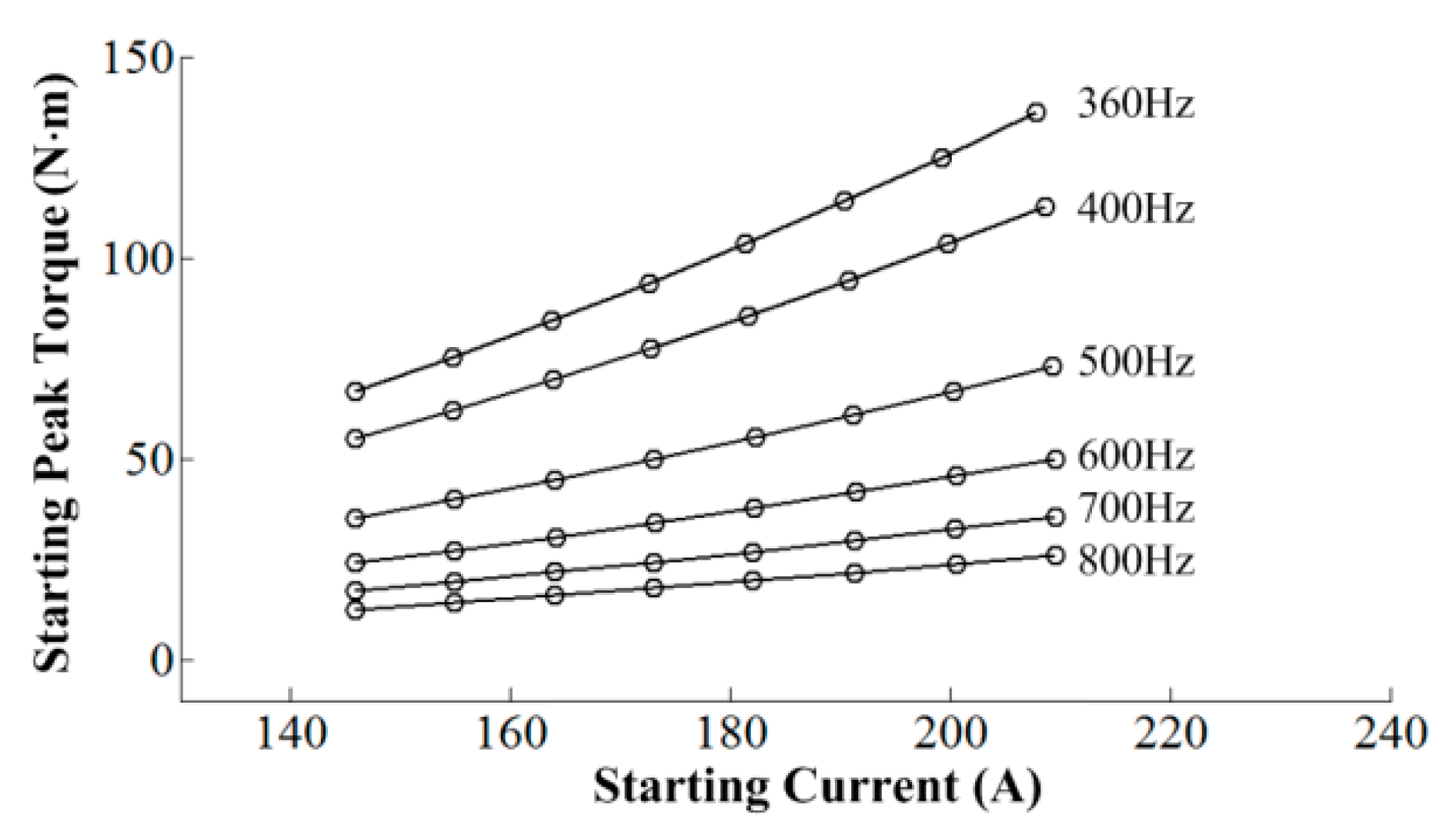
Firstly, the power supply of asynchronous motor is set to different frequencies, then it changes the U1 at each frequency f1. The basic motor parameters are obtained by the Ansoft simulation. The motor parameters are set in Simulink simulation for the motor model. The voltage and frequency of supply power are also changed, the Ist and Tstm are obtained through the dynamic characteristic simulation. The data relation between the Ist and Tstm is fitted according to the Formula (13). The fitting results are shown in Table 2 and the characteristics obtained are shown in Figure 5.
The similarity of fitted results is analyzed by using the total sum square (TSS) and the residual sum square (RSS) [24]. The calculated goodness of fit is above 0.98. Therefore, the Tstm description of motor is feasible.

4. Low-Frequency Step-Down Starting Method

As can be seen from Figure 2c, the variable frequency asynchronous motor has the maximum of Tstm with the low-frequency (360 Hz) power supply, and the mechanical damage is the greatest. Therefore, the Tstm with the low frequency is the research target.

4.1. Principle of Low-Frequency Step-Down Starting

From the Equation (3), it can be seen that the kst and km of aviation variable frequency asynchronous motor are proposed for the f1H power supply. The kst and km have a large margin with the low-frequency f1L power supply, that is, the Tst and Tem are greater than the design requirements. Therefore, if the power supply voltage is appropriately reduced with the low frequency, Tstm can be effectively reduced on the premise of meeting the Tst and Tem requirements.
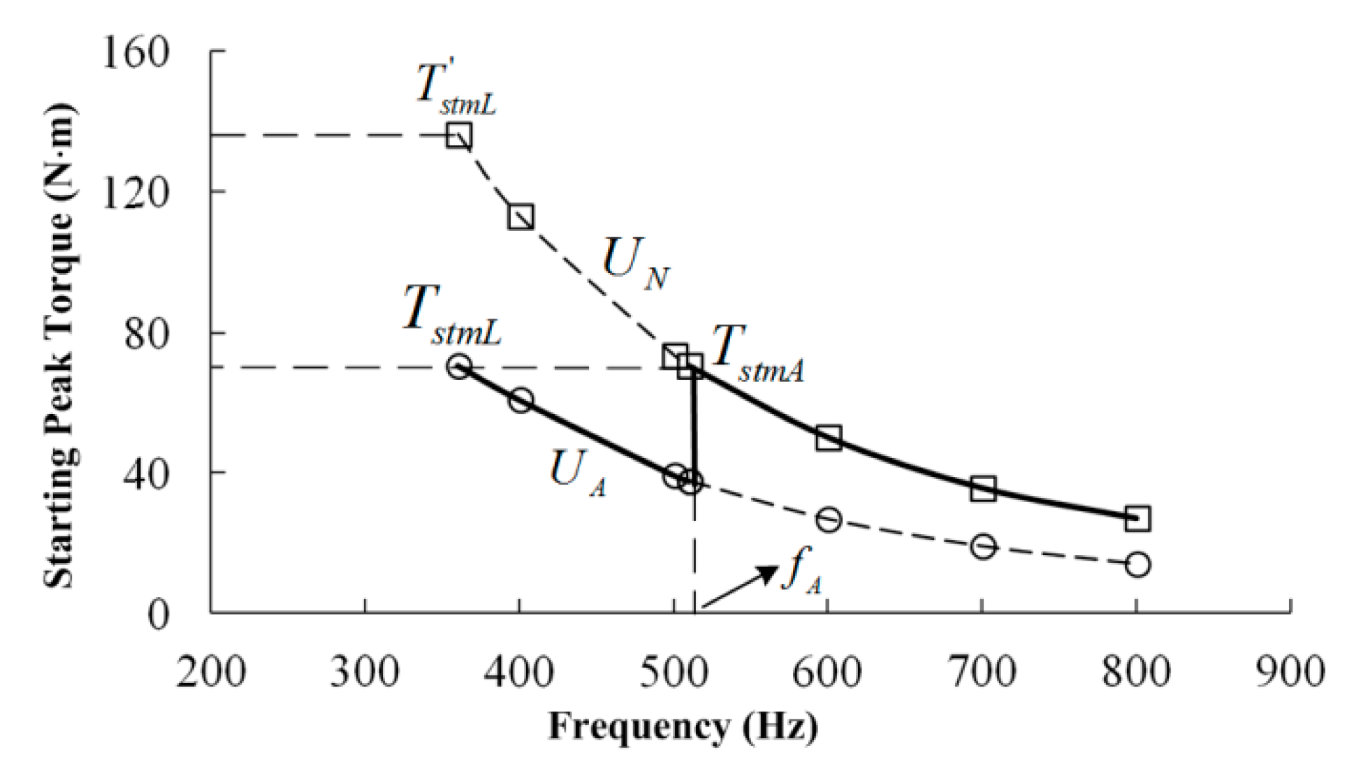
The frequency of variable frequency power supply is divided into the high-frequency band and the low-frequency band. The high-frequency band is started with the rated voltage UN, and the low-frequency band is started with the low voltage UA. The fA is the boundary between the two frequency bands. The starting voltage Ust is selected as follows: when f1fA, Ust = UN; when f1 < fA, Ust = UA. The Tstm characteristic is shown in Figure 6.
The selection principle of frequency boundary fA and the step-down voltage UA is given according to Figure 6. The design principle of step-down starting:
(1)
Principle I: The power supply voltage UA must ensure that kst and km meet the design requirements with the power frequency fA. If the working torque is TnA, the starting torque TstAkstTnA, and the critical torque TemAkmTnA;
(2)
Principle II: The TstmL with the power supply frequency f1L and the voltage UA is equal to the TstmA with the power supply frequency f1A and the voltage UN, that is, the maximum Tstm is the lowest in the entire frequency range.
For the low-frequency step-down starting shown in Figure 6, the voltage reduction, the series resistance and the series inductance can be adopted.

4.2. Design of Low-Frequency Voltage Reduction

The design method of voltage reduction with the low-frequency power supply is applied. Firstly, according to the design principle I, the reduced voltage UA should meet kst and km at the frequency boundary point fA. If the design is applied based on the starting torque TstA = kstTnA, it is:
k s t T n A = 3 p U A 2 R 2 2 π f A [ ( R 1 + R 2 ) 2 + 4 π 2 f A 2 ( L l 1 + L l 2 ) 2 ]
It is arranged to obtain:
U A 2 = 2 π f A T s t 3 p R 2 [ ( R 1 + R 2 ) 2 + 4 π 2 f A 2 ( L l 1 + L l 2 ) 2 ]
Designed with the critical torque TemA = kmTnA in the Equation (3), UA should meet at the frequency point fA:
k m T n A = 3 p U A 2 4 π f A [ R 1 + R 1 2 + 4 π 2 f A 2 ( L l 1 + L l 2 ) 2 ]
It is arranged to obtain:
U A 2 = k m T n A 4 π f A 3 p [ R 1 + R 1 2 + 4 π 2 f A 2 ( L l 1 + L l 2 ) 2 ]
According to the design principle II, the formula (13) is expressed as:
k s t m U N 2 ( R 1 + R 2 ) 2 + 4 π 2 f A 2 ( L l 1 + L l 2 ) 2 = U A 2 ( R 1 + R 2 ) 2 + 4 π 2 f 1 L 2 ( L l 1 + L l 2 ) 2
In order to simplify the calculation, it is approximately ( R 1 + R 2 ) 2 < < 4 π 2 f A 2 ( L l 1 + L l 2 ) 2 and written as:
U A 2 k s t m ( R 1 + R 2 ) 2 + 4 π 2 f 1 L 2 ( L l 1 + L l 2 ) 2 4 π 2 f A 2 ( L l 1 + L l 2 ) 2 U 1 N 2
Coupled, the (15) and (19) or (17) and (19), the fA and UA can be estimated.

4.3. Design of Low-Frequency Series Resistance

If the stator winding with the series resistance is used to reduce the power supply voltage for the low-frequency power supply, it is necessary to estimate the frequency boundary point fA and the series resistance RA.
Similarly, according to the design principle I, it is calculated by the starting torque TstA = kstTnA at the point fA, and the starting torque should satisfy:
k s t T n A = 3 p U n 2 R 2 2 π f A [ ( R 1 + R A + R 2 ) 2 + 4 π 2 f A 2 ( L l 1 + L l 2 ) 2 ]
The total resistance value R = R1 + RA + R’2 should meet:
R Σ 2 = 3 U N 2 R 2 k s t P N 4 π 2 f A 2 ( L l 1 + L l 2 ) 2
However, it is calculated by the Tem = kmTnA at the point fA, defines R1 = R1 + RA, and meets:
k m T n A = 3 p U n 2 4 π f A [ R 1 Σ + R 1 Σ 2 + 4 π 2 f A 2 ( L l 1 + L l 2 ) 2 ]
The R1 is:
R 1 Σ = 3 p U n 2 8 π f A k m T n A 8 π 3 k m T n A 3 p U n 2 f A 3 ( L l 1 + L l 2 ) 2
According to the design Principle II, the Equation (13) is:
k s t m U N 2 ( R 1 + R 2 ) 2 + 4 π 2 f A 2 ( L l 1 + L l 2 ) 2 = U N 2 ( R 1 + R 2 + R A ) 2 + 4 π 2 f 1 L 2 ( L l 1 + L l 2 ) 2
Due to the fA > f1L, it is approximately ( R 1 + R 2 ) 2 < < 4 π 2 f A 2 ( L l 1 + L l 2 ) 2 , and written as:
R Σ 2 4 π 2 ( L l 1 + L l 2 ) 2 [ 1 k s t m f A 2 f 1 L 2 ]
Coupled the (21) and (25) or (23) and (25), the fA and RA can be estimated.

4.4. Design of Low-Frequency Series Inductance

It reduces the power supply voltage of asynchronous motor by the series inductance. However, the voltage drop across the inductor is not only related to the starting current, but also to the frequency. Its characteristics are different from the series resistance. The frequency boundary point fA and the series resistance LA are estimated.
Similarly, according to the design principle I, it is calculated by the starting torque TstA = kstTnA at the point fA, and it should satisfy:
k s t T n A = 3 p U n 2 R 2 2 π f A [ ( R 1 + R 2 ) 2 + 4 π 2 f A 2 ( L l 1 + L A + L l 2 ) 2 ]
The total inductance value L = Ll1 + LA + L’l2 should meet:
L Σ 2 = 1 4 π 2 f A 2 [ 3 p U n 2 R 2 2 π f A k s t T n A ( R 1 + R 2 ) 2 ]
However, it is calculated by the Tem = kmTnA at the point fA, and meets:
k m T n A = 3 p U n 2 4 π f A [ R 1 + R 1 2 + 4 π 2 f A 2 ( L l 1 + L A + L l 2 ) 2 ]
It is expressed as:
L Σ 2 = 3 p U n 2 16 π 3 f A 4 k m T n A ( 3 p U n 2 4 π k m T n A 2 R 1 f A )
According to the design Principle II, the Equation (13) is:
k s t m U N 2 ( R 1 + R 2 ) 2 + 4 π 2 f A 2 ( L l 1 + L l 2 ) 2 = U N 2 ( R 1 + R 2 ) 2 + 4 π 2 f 1 L 2 ( L l 1 + L A + L l 2 ) 2
It is approximately ( 1 / k s t m 1 ) ( R 1 + R 2 ) 2 < < 4 π 2 f A 2 ( L l 1 + L l 2 ) 2 , and written as:
L Σ 2 = ( L l 1 + L A + L l 2 ) 2 f A 2 k s t m f 1 L 2 ( L l 1 + L l 2 ) 2
Coupled the (27) and (31) or (29) and (31), the fA and LA can be estimated.

4.5. Design Example of Low-Frequency Step-Down Starting

The variable frequency asynchronous motor shown in Table 1 is taken as an example, and the design methods of voltage reduction, the series resistance, and the series inductance are respectively applied. It is assumed that the constant power load is driven, and the motor starts with load at the same time for meeting kst the design requires kst = 1.2~1.4. Coupled with the (15) and (19), (21) and (25), (27) and (31), respectively. The simulation results are shown in Table 3.
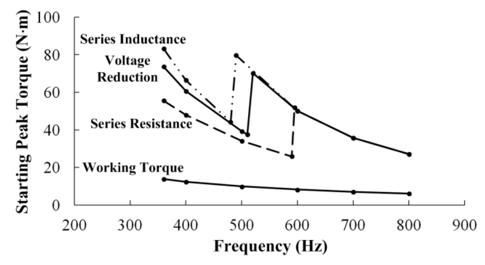
The starting peak torque characteristics of voltage reduction methods are shown in Figure 7.
The motor starts with the rated voltage, and the peak torque Tstm of power supply with f1L (360 Hz) is 135.49 N·m. As can be seen from the data in the Table 3, it respectively reduces to 54%, 41% and 61% of the the peak torque Tstm with 360 Hz power supply. The effect of series resistance is the best.
The above mentioned design methods may not achieve the goal of principle II, since the approximate relationship is used and it is affected by magnetic saturation. If the gap between TstmL and TstmA is large, it needs to adjust appropriately. When TstmL is larger than TstmA, the voltage UA can be appropriately reduced, or the step-down resistor RA or inductance LA can be increased. At the same time, in order to ensure the requirement of kst, the frequency boundary point fA can be appropriately reduced.

5. Characteristic Analysis of Low-Frequency Step-Down Starting

5.1. Characteristics of Starting Peak Torque

The aviation variable frequency asynchronous motors apply three kinds of low-frequency step-down starting methods by the voltage reduction, the series resistance, and the series inductance. According to the characteristics of starting peak torque Tstm shown in Figure 7, it has the following characteristics:
(1)
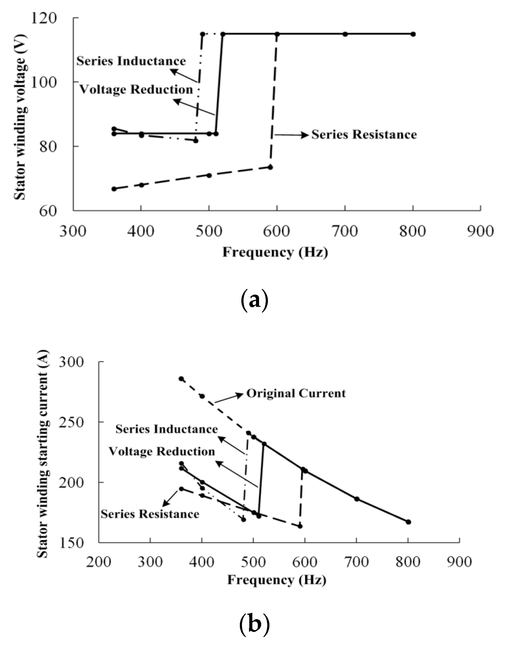
The series resistance method has the better suppression effect on the starting peak torque Tstm, as shown in Figure 8a. When the power supply frequency f1 decreases in the low-frequency stage, the voltage drop across the resistor RA increases due to the increase of starting current Ist. The voltage on the stator winding reduces to make Tstm decrease effectively.
(2)
The series inductance method has the poor suppression effect on the starting peak torque Tstm, as shown in Figure 8a. When the power supply frequency f1 decreases in the low-frequency stage, the impedance on the inductor LA decreases linearly. However, the starting current Ist does not increase linearly. The voltage drop on the inductor LA reduces and the voltage on the stator winding increases, causing the larger low-frequency Tstm.
(3)
The disadvantage of series resistance method is that it consumes the parts of power and causes the resistor heat. Therefore, it needs to be analyzed for the asynchronous motor that requires frequent starting. For the long-time work motor, the power consumed can be ignored since the starting time is short.

5.2. Characteristic Analysis of Starting Current

The surge current during the traditional asynchronous motor starting is always considered as an important factor affecting the power supply stability. The starting current of variable frequency asynchronous motor can be expressed as:
I s t = U 1 ( R 1 + R 2 ) 2 + 4 π 2 f 1 2 ( L l 1 + L l 2 ) 2 3 p n U 1 2 R 2 2 π f 1 ( L l 1 + L l 2 )
As seen from Equation (32), the starting current Ist is approximately inverse proportional to the power frequency f1. For the variable frequency asynchronous motor with the rated voltage, the starting current Ist with the high-frequency (800 Hz) is 167.2A, and the starting current Ist with low frequency (360 Hz) is 286.3A, as shown in Figure 8b.
The low-frequency step-down starting can also suppress the surge current Ist during the starting. The starting current Ist of step-down methods is shown in Figure 8b. The maximum is at the frequency boundary point with the rated voltage.
(1)
The frequency boundary point of series resistance method is the highest, and the starting current is the smallest with the rated voltage, which is 214A. The frequency boundary point of series inductance method is the lowest, and the starting current is the largest, which is 243A. The voltage reduction method is center, and the current is 236A.
(2)
For the starting current at the frequency f1L, the series resistance method has the lowest voltage, and the starting current is also the lowest, which is 195A. The starting currents of voltage reduction and the series inductance are 212A and 216A, respectively. The effect of series resistance is the best.

5.3. Simulation Test and Analysis of Starting Process

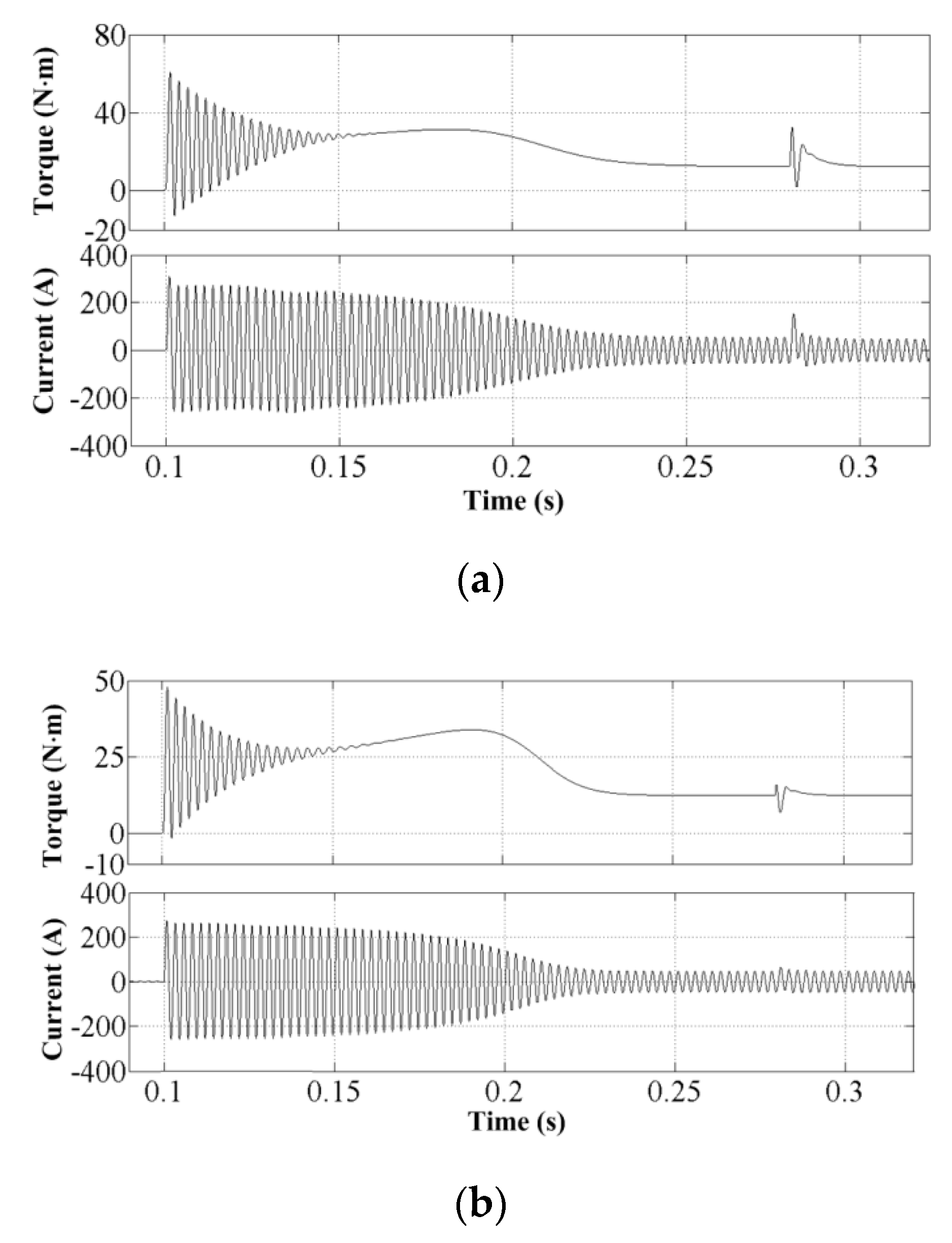
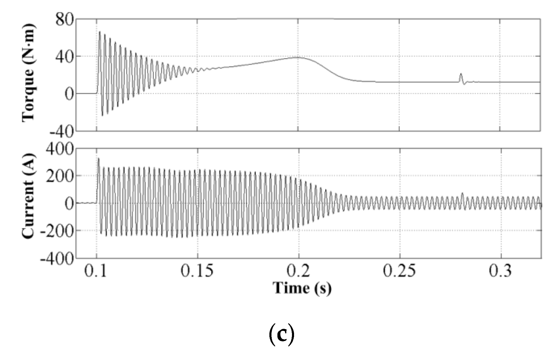
The power supply frequency of variable frequency asynchronous motor is set with 400 Hz, and the load torque is 12.46 N·m, which is the rated torque. Three kinds of low-frequency step-down starting methods are used for the simulation test, and the normal power supply is restored after the starting at the 0.28 s. The characteristics of torque and phase current are shown in Figure 9.
The Table 4 shows the simulation data of starting process with the step-down voltage methods. The steady-state torque shown in Figure 9 is 12.46 N·m, the effective value of steady-state phase current is 35.15A, and the peak value is 49.7A.
The ∆IAm of switching characteristics is the fluctuation value based on the steady-state peak current (49.7A), which can be seen from the data in Table 4:
(1)
The starting torque Tstm of three methods is consistent with the characteristics of Figure 7. The series resistance method is the smallest, and the starting torque Tst is not a huge different.
(2)
The starting current Ist of three methods is consistent with the characteristics of Figure 8b, and series resistance method is the smallest.
(3)
After the step-down starting is completed, the normal power supply switching is restored, and the ΔTem, ΔIAm of series resistor method are the smallest.

5.4. Experiment of Pump-Type Variable Frequency Asynchronous Motor

The 850 W pump-type variable frequency asynchronous motor with the narrow frequency conversion (360~600 Hz) is used to test the starting characteristics. The parameters of prototype are shown in Table 5.
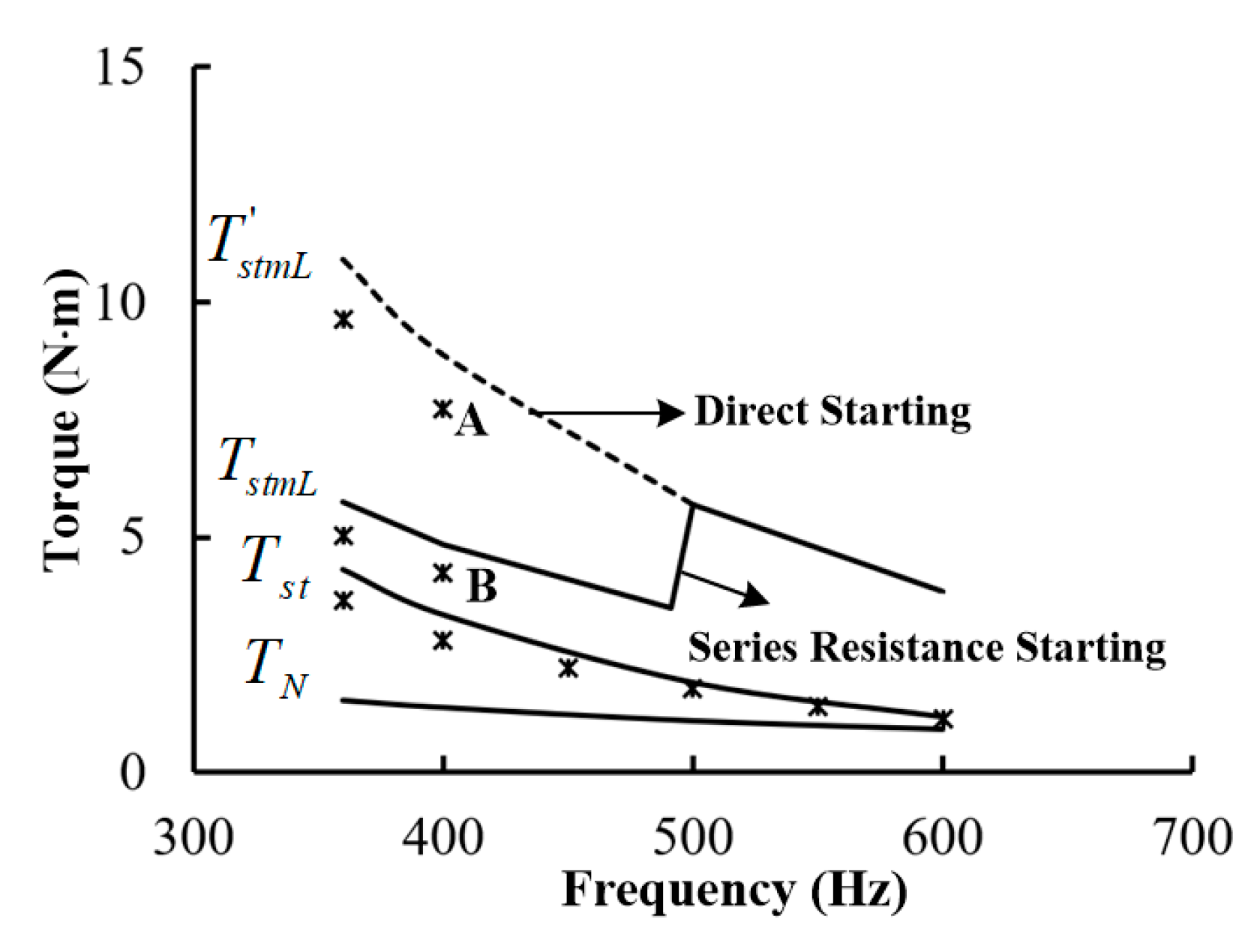
For the experiments of the variable frequency asynchronous motor, two experiments are performed, namely the starting (stall) experiment and the starting torque dynamic experiment. The AC variable frequency power supply uses a capacity of 30 kVA. The output frequency of power supply can be adjusted in a wide range from 300~800 Hz, and the output voltage range is from 92.0~150.0 V. For the strating (stall) test, the prototype is placed on the torque bench and connected to the 30kVA power electronic variable frequency power supply and carried out the stall test with diffrernt frequncies, shown in Figure 10. It is approximately taken as the starting torque analysis. The straight line is the simulation characteristic with the motor design data, and the “*” is the experimental data. It can be seen that the experimental torque is significantly lower than the simulation value with the low frequency, and the reason is the low-frequency saturation factor.
For the starting torque dynamic experiment, the prototype was placed on a loadable speed regulation test bench. The experimental equipments mainly include the 30KVA AC variable frequency power supply, the pump-type variable frequency asynchronous motor, the adjustable resistance box, and the digital oscilloscope. According to the series resistance design method of low-frequency step-down starting, the series resistance is 2 Ω. The purpose of experiment is to verify the current and torque starting characteristics of variable frequency asynchronous motor with the direct starting and the series resistance starting. For the direct starting experiment, the AC variable frequency power supply is adjusted to the 115 V/400 Hz output, and directly connected to the variable frequency motor at a certain time, recording the current data through the oscilloscope. For the series resistance starting, the AC variable frequency power supply is also adjusted to the 115 V/400 Hz output, and connected the resistor of 2 Ω. The variable frequency motor is connected at a certain time, recording the current data through the oscilloscope.
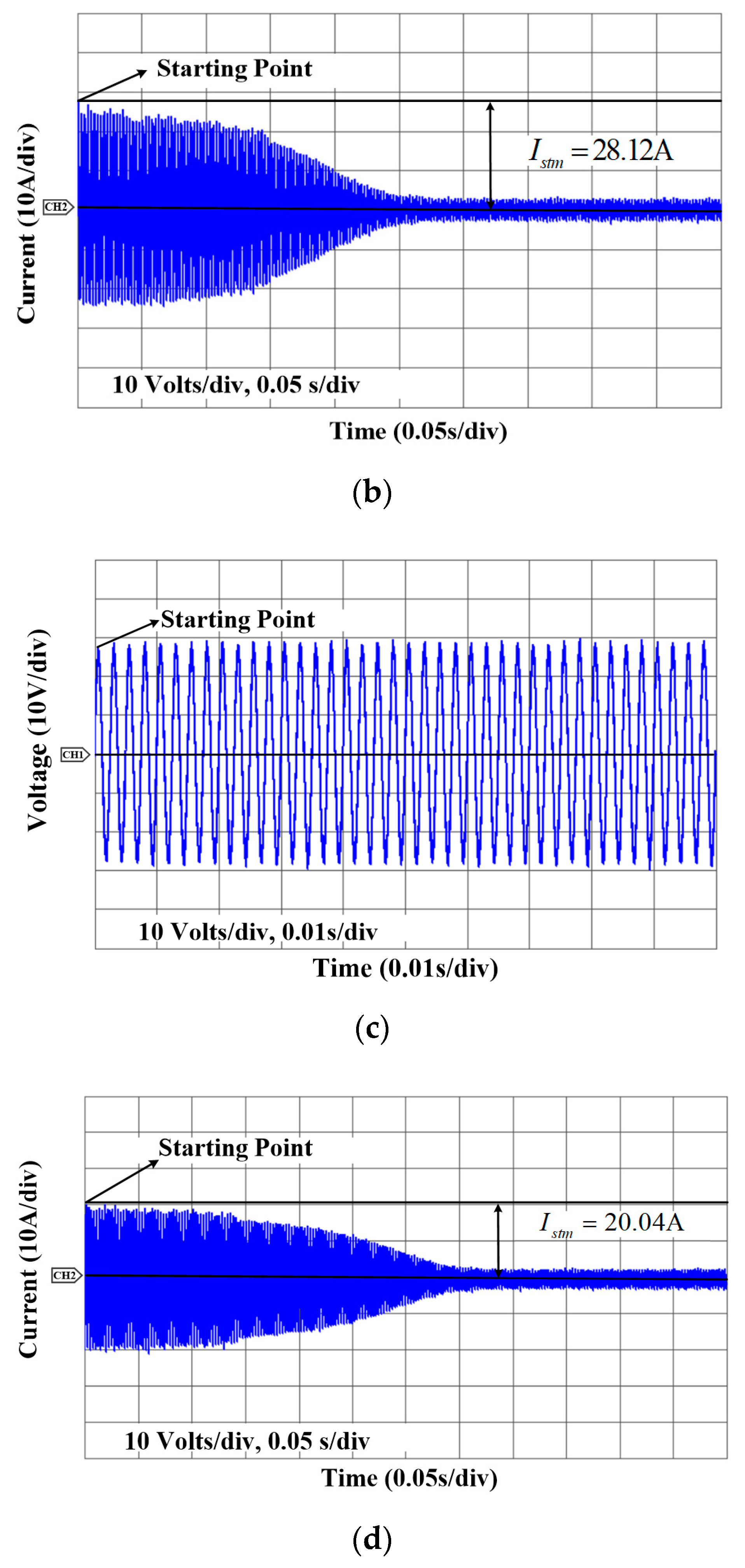
The dynamic experiment of starting process can measure the three-phase voltage and current. The A-phase voltage and current waveforms are shown in Figure 11. Figure 11a–c shows the voltage waveforms with the direct starting and the series resistance starting. When the motor starts, the voltage drops the 3.5% and 5.2%, respectively. Figure 11b–d shows the current waveforms with the direct starting and the series resistance starting, and the peak current reaches 28.12A and 20.04A, respectively.
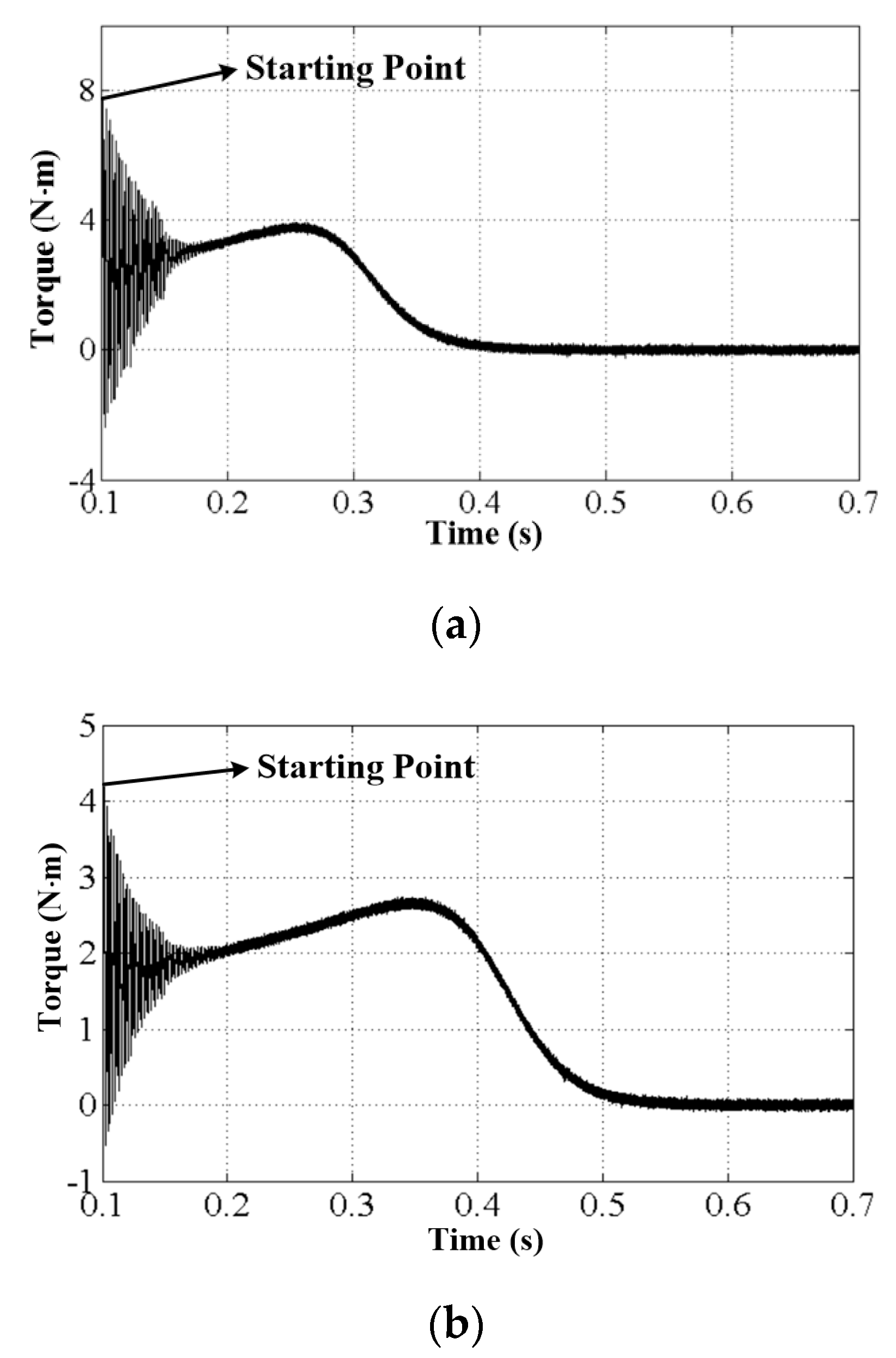
In order to obtain the approximate trend of stating pulse vibration torque, the rotor current is calculated by using Formula (6) and the dynamic torque is calculated by using Formula (9). Figure 12a–b shows the torque waveforms with the the direct starting and the series resistor starting.
The peak torque reaches 7.78 N·m and 4.21 N·m, respectively. The peak torque is 45.89% less than the peak torque with the direct starting.
Obviously, the data of A point and B point shown in Figure 10 can be expressed separately the change trend with the direct starting and the series resistance starting. The peak torque of experimental data is smaller than that of simulation, since the power supply exhibits the voltage transient drop effect during the starting.

6. Conclusions

The strating pulse vibration torque of aviation variable frequency asynchronous motor is taken as the research object. The design methods of low-frequency step-down starting is proposed, which are the voltage reduction, the series resistance, and the series inductance according to a novel approximate model by the data fitting for peak torque generated by the starting pulse vibration torque. The paper also proposes the estimation algorithm of parameters and analyzes and compares the starting pulse vibration torque characteristics. The research and experiment results show that the low-frequency step-down starting can effectively reduce the pulse vibration torque and the surge current during the low-frequency starting. The series resistance method has the better effect on the peak torque caused by the starting pulse vibration torque and the starting current suppression, which is suitable for the variable frequency asynchronous motor drive system with the infrequent starting. The actual motor model establishment is worth considering in future research.

Author Contributions

Z.C. and Y.Z. formulated the research content of energy consumption characteristics based on more electric aircraft. Z.C. consulted the papers, derived formulas, modeled and simulated for the energy consumption characteristics of more electric aircraft actuation system and the traditional aircraft actuation system. N.W. enriched and supplemented the content of power loss. Z.C. and N.W. also modified the paper language. All authors have read and agreed to the published version of the manuscript.

Funding

This work was supported by the Aviation Nature Fund (2014ZC01002).

Conflicts of Interest

The authors declare no conflict of interest. The funders had no role in the design of the study; in the collection, analyses, or interpretation of data; in the writing of the manuscript, or in the decision to publish the results.

References

  1. Xie, L.R.; Wang, Z.Y.; Chou, Q. Research on mechanical characteristics of squirrel cage asynchronous motor. J. Chin. Electr. Eng. Sci. 2008, 28, 68–72. [Google Scholar]
  2. Yetgin, A.G. Investigation of Effects of Stator Slot Permeance on Induction Motor and Obtaining the Best Starting Torque Using Permeance Calculation. Electr. Comput. Eng. 2020, 43, 25–29. [Google Scholar]
  3. Kia, S.H.; Henao, H. Torsional Vibration Assessment Using Induction Machine Electromagnetic Torque Estimation. IEEE Trans. Ind. Electron. 2009, 57, 209–219. [Google Scholar] [CrossRef]
  4. Xie, Y.; Pi, C.; Li, Z.W. Study on Design and Vibration Reduction Optimization of High Starting Torque Induction Motor. Energies 2019, 12, 1263. [Google Scholar]
  5. Kia, S.H.; Henao, H.; Capolino, G.A. Torsional Vibration Effects on Induction Machine Current and Torque Signatures in Gearbox-based Electromechanical System. IEEE Trans. Ind. Electron. 2009, 56, 4689–4699. [Google Scholar]
  6. Huang, X.Z.; Li, Q.F.; Zhao, X.Y. Research on Pulse Torque of Three-phase Asynchronous Motor Based on Skew Slot. J. Electrotech. Soc. 2015, 7, 194. [Google Scholar]
  7. Widdle, R.D.; Krousgrill, C.M.; Sudhoff, S.D. An Induction Motor Model for High-frequency Torsional Vibration Analysis. J. Sound Vib. 2008, 290, 865–881. [Google Scholar] [CrossRef]
  8. Abdel-Rahim, N.M.B.; Shaltout, A. Cost-Effective Control Scheme for Reduction of Torsional Torque Oscillations in Starting Large Induction Motors. Electr. Power Compon. Syst. 2006, 34, 1163–1175. [Google Scholar] [CrossRef]
  9. Wheller, P. Technology for the More and All Electric Aircraft of Future. In Proceedings of the International Conference on Automatic, Curico, Chile, 19–21 October 2016. [Google Scholar]
  10. Piancastelli, L.; Gatti, A.; Frizziero, L.; Ragazzi, L.; Cremonini, M. CFD Analysis of Zimmerman’s V173 Stol Aircraft. J. Eng. Appl. Sci. 2015, 10, 8063–8070. [Google Scholar]
  11. Rosero, J.A.; Ortega, J.A.; Aldabase, E. Moving Towards a More Electric Aircraft. IEEE Aerosp. Electron. Syst. 2007, 22, 3–9. [Google Scholar]
  12. Li, W.L.; Yang, Y.; Zhang, X.B. Digital Generator Control Unit Design for a Variable Frequency Synchronous Generator in MEA. Energies 2018, 11, 96. [Google Scholar] [CrossRef] [Green Version]
  13. Du, X.F.; Hou, Y.Z.; Sun, C. Optimization Analysis of Rectangular Rotor Slot Structure of Squirrel Cage Asynchronous Motor under Aviation Variable Frequency Power. J. Aeronaut. 2015, 36, 614–624. [Google Scholar]
  14. Charles, O.; Moataz, E.; Augustin, M.M. Multi-Phase Modular Drive System: A Case Study in Electrical Aircraft Applications. Energies 2018, 11, 5. [Google Scholar]
  15. Zheng, X.C.; Gao, F.; Husan, A. A Droop Control Based Three Phase Bidirectional AC-DC Converter for More Electric Aircraft Applications. Energies 2017, 10, 400. [Google Scholar] [CrossRef] [Green Version]
  16. Benarous, M. Design of a Director On-Line Induction Motor for Variable Frequency Aerospace Application. In Proceedings of the IET International Conference on Power Electronics, Machines and Drives, Dublin, Ireland, 4–6 April 2006; pp. 202–206. [Google Scholar]
  17. Du, X.F.; Wang, D.Q. Transient Simulation Studies of Squirrel-cage Induction Motor Directly Supplied with Aircraft Variable Frequency Power. In Proceedings of the IEEE Electrical machines and System, Busan, Korea, 26–29 October 2013; pp. 2000–2005. [Google Scholar]
  18. Du, X.F. Study on Performance Characteristics of Induction Motor operated with Aero Variable Frequency Power Supply. Ph.D. Thesis, Beihang University, Beijing, China, 2014. [Google Scholar]
  19. Cao, Z.; Zhou, Y.J.; Han, Z.L.; Guo, B.T. Design Stress Analysis of Mechanical Equipment for Aviation Variable Frequency Asynchronous Motors. J. Micromotor 2018, 51, 1–5. [Google Scholar]
  20. Li, S.M. Mechanical Fatigue and Reliability Analysis, 1st ed.; Science Press: Beijing, China, 2006. [Google Scholar]
  21. Mroz, J.; Wojciech, P. Improvement of Thermal and Mechanical Strength of Starting Cage of Double-Cage Induction Motors. Energies 2019, 12, 4551. [Google Scholar] [CrossRef] [Green Version]
  22. Abdel-Rahim, N.M.B.; Shaltout, A. Torsional Vibration Control of Large Induction Motors Using Constant Air Gap Flux Cheme. IET Electr. Power Appl. 2012, 8, 515–522. [Google Scholar]
  23. Feehally, T.; Damián, I.E.; Apsley, J.M. Analysis of Electromechanical Interaction in Aircraft Generator Systems. IEEE Trans. Ind. Appl. 2016, 50, 4327–4335. [Google Scholar] [CrossRef] [Green Version]
  24. Liu, L.H. The Comparison and Test Check for Goodness of Fit. J. Yangtze Univ. 2013, 10, 14–16. [Google Scholar]
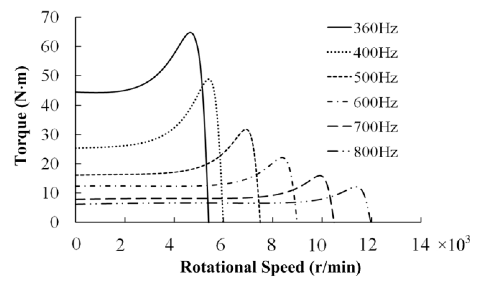
Figure 1. Mechanical characteristics of asynchronous motor with aviation variable frequency power supply.
Energies 13 01337 g001
Figure 2. Starting peak torque of asynchronous motor. (a) Starting process of constant frequency asynchronous motor. (b) Starting process of variable frequency asynchronous motor. (c) The relationship between the starting pulse vibration torque and the power supply frequency.
Energies 13 01337 g002
Figure 3. Current and torque of starting process. (a) Current waveform. (b) Torque waveform.
Energies 13 01337 g003aEnergies 13 01337 g003b
Figure 4. Schematic diagram of asynchronous motor magnetic potential.
Energies 13 01337 g004
Figure 5. Fitting curves of starting peak torque.
Energies 13 01337 g005
Figure 6. Starting peak torque with the low-frequency step-down starting.
Energies 13 01337 g006
Figure 7. Starting peak torque characteristics with the low-frequency step-down starting.
Energies 13 01337 g007
Figure 8. Comparison of voltage and current characteristics. (a) Stator winding voltage (b) Stator winding starting current.
Energies 13 01337 g008
Figure 9. Comparison of torque and current characteristics. (a) Voltage reduction starting process (b) Series resistance starting process. (c) Series inductance starting process.
Energies 13 01337 g009aEnergies 13 01337 g009b
Figure 10. The data comparison of simulation and experiment.
Energies 13 01337 g010
Figure 11. The experimental voltage and current comparison. (a) The voltage with the direct starting (b) The current with the direct starting. (c) The voltage with the series resistance starting. (d) The current with the series resistance starting.
Energies 13 01337 g011aEnergies 13 01337 g011b
Figure 12. The experimental torque comparison. (a) The torque with the direct starting. (b) The torque with the series resistance starting.
Energies 13 01337 g012
Table 1. Parameters of variable frequency asynchronous motor.
ParametersValue
PN (kW)7.5
p4
R1 (Ω)0.12
Ll1 (mH)0.06035
R’2 (Ω)0.147
L’l2 (mH)0.08715
Lm (mH)1.986
Table 2. Starting peak torque coefficient.
FrequencyCstmkstm
3600.001661
4000.001530.92
5000.001290.78
6000.001140.69
7000.001030.62
8000.000940.57
Table 3. Design data of low-frequency step-down starting.
Control ParametersVoltage ReductionSeries ResistanceSeries Inductance
fA (Hz)510590480
Step-down DataUA = 84 VRA = 0.242 ΩLA = 0.091 mH
TnA (N·m)9.758.4510.38
TstA (N·m)13.2311.1512.68
kstA1.361.321.22
TstmA (N·m)70.25277.71
TstmL (N·m)73.6355.583.13
Table 4. Simulation data of starting process by different step-down methods.
Control MethodsStarting CharacteristicsSwitching Characteristics
ParametersTstm (N·m)Tst (N·m)Ist (A)∆Tem (N·m)∆IAm (A)
Voltage reduction60.7324.07219.8520.2571.06
Series resistance47.8723.23193.585.617.37
Series inductance66.4321.19231.588.8214.08
Table 5. Parameters of pump-type motor.
ParametersValue
R1 (Ω)1.381
Ll1 (mH)0.612
R’2 (Ω)1.762
L’l2 (mH)1.328
Lm (mH)10.226