Abstract
Due to global climate change and fossil fuel depletion, the rational use of thermal energy has attracted great research interest. Large differences between indoor and outdoor temperatures in cold regions results in huge amounts of heat waste and drop in indoor humidity. Ventireg, an adsorption method, has been often recommended for heat and humidity regeneration in cold countries. In this research work, VentireC, an advanced method employing two thermally coupled adsorbent beds is discussed. It allows the heat released during adsorption of moisture in one adsorber to be transferred to another adsorber to facilitate water desorption. The VentireC approach is comprehensively analysed and described in this paper. A composite adsorbent based on LiCl in silica gel pores, which can exchange up to 0.5 g-H2O/g-sorbent, is selected for VentireC processes under cold Western Siberia conditions. Mathematical simulation of humidity recuperation, employing the selected sorbent with and without thermal coupling, demonstrates the advantages of the VentireC process.
1. Introduction
Owing to enhanced living standards, heating and cooling (H/C) has become one of the biggest energy sectors, and is forecasted to remain so. H/C is responsible for almost half of the global energy consumption, more than electricity or transport [1]. In Russia, Canada, and the northern part of Europe, heating is vital. The duration of the heating period in Russia varies from 6 to 9 months for different climatic zones. According to Ministry of Energy of the Russian Federation [2], the total heat production in Russia in 2016 was 5.3⋅109 GJ. About 97% of this heat is produced from fossil fuels (the share of gas, solid, and liquid fuels was 75%, 20%, and 2%, respectively), greatly contributing to greenhouse gas emissions. Less than half of the heat is produced by cogeneration stations (heat and electricity) and almost 60% by boilers. In Russia, space heating is responsible for 58% of the overall energy consumption in residential buildings with district heating systems, which cover c.a. 75% of all dwellings [3]. Due to current global climate change and depletion of fossil fuels, the rational use of thermal energy in dwellings has become a hot topic.
Large differences between indoor and outdoor temperatures result in a huge amount of heat waste through building walls, roofs, flow, windows, and ventilation systems. The structure of heat losses in buildings demonstrate three tendencies:
- the increasing standards for thermal protection of buildings, set in 2003, resulted in the reduction of specific energy consumption from 0.97 to 0.38 GJ/(m2 year)
- the fraction of heat loss due to air infiltration is essentially larger for multi-storied blocks of flats than for individual low-rise buildings, for which heat loss in construction is dominant
- this fraction grows significantly for modern buildings with better thermal insulation; it reaches 30% and almost 50% in low-rise and high-rise buildings, respectively
Therefore, a further improvement in a dwelling’s thermal efficiency might be associated with a decrease in heat loss in ventilation systems [3,4]. The use of heat recovery ventilators (HRVs) in buildings can reduce energy consumption by heating incoming fresh air. HRVs can recover 60–95% of the heat, depending on heat exchanger performance and climatic conditions [4]. However, in cold climates, HRV operation is limited due to moisture freezing inside the unit’s exhaust, caused by high moisture content in outlet air [5,6].
Another vital issue associated with air infiltration in buildings during winters in cold countries is a dramatic drop in indoor humidity down to 10–20% [7], which is far below the comfort level (40–60%). Heating, ventilating, and air conditioning systems (HVAC) and humidifiers can partially alleviate this problem. However, the complex HVACs, which maintains both temperature and humidity, are expensive and energy-consuming. A large volume of air passing through evaporative and ultrasonic humidifiers promotes rapid growth of mould and bacteria, resulting in allergies and lung diseases. For these reasons, the development of new energy-saving ways to manage indoor temperature and moisture balance has garnered research interest.
An effective Ventireg method for simultaneous heat and humidity regeneration in ventilation systems in cold countries was suggested and tested in [8]. In the Ventireg process, indoor air passes through adsorbent (Ad) and heat-storing (HS) beds, where indoor moisture and heat are respectively absorbed. Outdoor air then passes in the opposite direction, extracts the stored heat and moisture, thus maintaining indoor temperature and humidity balance. This approach reduces heat loss, avoids ice formation at the unit’s exit point, and humidifies the supplied air to ensure comfortable indoor conditions. This system achieved energy recovery up to 95%, while 70–90% of the moisture was returned to the room, simultaneously preventing ice formation, as tested under climatic conditions in Western Siberia [8]. The Ventireg is excellently adapted for cold countries, as its efficiency increases with a larger difference between indoor and outdoor temperatures.
Although the Ventireg is effective for regeneration of heat and moisture in ventilation systems [9], its performance is strongly restricted by (i) significant consumption of electric power for blowing of air through fixed Ad and HS beds, and (ii) increase in Ad bed temperature due to releasing of adsorption heat. Both these parameters reduce the efficiency of moisture and heat regeneration. To lower the required fan power, a novel enthalpy recovery ventilator based on compact disc-type sorbent bed was suggested and tested in [10]. The prototype recovered up to 70% of heat and 80% of moisture from exhaust air with 60% less pressure drop, as compared with a fixed granulated adsorbent bed. To overcome adsorbent heating during adsorption, desiccant systems using a heat exchanger coated with an adsorbent layer were proposed in [11]. Here, air dehumidification is more effective than in fixed Ad bed, since the adsorption heat is withdrawn by heat transfer fluid (HTF) flowing through the heat exchanger. During air humidification, the heat for water desorption is supplied to the adsorbent by HTF flow. Thus, the sensible and latent loads are decoupled, which makes it possible to separately manage and enhance unit performance [12].
A large number of Desiccant Coated Heat Exchangers (DCHEs) based on silica gel [13], FAM [11,14], silica-alumina-phosphate SAPO-34 [15], metal-organic framework MIL-100(Fe) [16] have been developed. Their feasibility has been successfully demonstrated for open desiccant air cooling [17] and heating systems [18], desiccant enhanced vapour compressed heat pumps [19], desiccant humidity control systems [20], and air dehumidification [21] systems.
This study is aimed at enhancing the efficiency of heat and moisture exchange between incoming and outgoing air fluxes in the ventilation systems of buildings. An advanced VentireC approach for heat and moisture reCuperation in Ventilation systems in cold countries, as suggested in [22], is presented. It employs two desiccant-coated heat exchangers (HEx) [14,23], connected to each other to remove latent load during water adsorption. The advantages of this approach are demonstrated by mathematical simulation of the VentireC process. The simulation was carried out for sorbent LiCl/silica, which belongs to the family of composites “Salt inside Porous Matrix” (CSPMs), widely used for multiple energy applications [24,25]. The water sorption equilibrium on the LiCl/silica matches well with the climatic conditions in Western Siberia [22].
2. Description of the VentireC Process
First, the difference between the common Ventireg method [8] and the new VentireC approach is discussed. The Ventireg unit consists of an Ad bed, located inside the unit close to the room; and an HS bed placed close to the outdoors (Figure 1a). During the outflow stage of the Ventireg process (Figure 2), indoor air with comfort temperature Tin and relative humidity RHin (point 1, Figure 2) enters the dry Ad bed, where the moisture is adsorbed. Due to the released heat, the air and adsorbent are heated (line 1–2). If no heat is transferred from the Ad bed through the walls, the process is almost adiabatic. It then passes through the HS bed (2–3), where sensible heat is absorbed and exits the unit as cold and dry (point 3: Tout, humidity ratio Xout). In the inflow stage, the cold and dry outdoor air enters the HS bed (line 3–2), absorbs the stored heat, and becomes warm. It then enters the wet Ad bed, where the retained moisture is desorbed and returns to the room, thus partially recovering the indoor humidity.
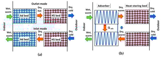
Figure 1.
Schematic representations of the Ventireg (a) and VentireC (b) processes.

Figure 2.
Ventireg (1–2–3) and VentireC (1–2’–3) processes in a psychrometric chart of wet air. Outflow stage—red line, inflow stage—blue line.
Practical realization of the Ventireg process revealed two main disadvantages [8]:
- Its energy efficiency is reduced due to significant consumption of electric power to blow air through the fixed Ad and HS beds in a larger unit.
- The heat released during the water adsorption process increases the temperature of the adsorbent. The humidity ratio, X, of the process air, increases, thus reducing dehumidification efficiency. Furthermore, at increasing temperatures, the dehumidification capacity of the adsorbents decreases, thus requiring a larger adsorbent loading, which further increases electricity consumption to blow air.
These drawbacks dramatically reduce the efficiency of heat and humidity regeneration. They can be overcome by employing two thermally coupled DCHEs, instead of fixed Ad beds.
The VentireC unit consists of two blocks of (DCHE + HS) beds, which operate in opposite modes (Figure 1b). The heat released during water vapour adsorption in DCHE1 during the outflow mode is removed by cold HTF and transferred directly to DCHE2, which operates in an inflow mode. Due to the latent heat removal from DCHE1, water adsorption occurs isothermally (line 1—2’ in Figure 2); this is expected to facilitate air dehumidification. Simultaneously, the heat transferred to the DCHE2 is consumed by the wet adsorbent and assists in water desorption and humidification of the outdoor air. The heat storage in the VentireC is similar to that of the Ventireg: the outflow air passes through the HS1 bed, where sensible heat is absorbed. Simultaneously, the stored heat is released to inflow air in the HS2 bed. To continuously treat the latent and sensible loads, two blocks of (DCHE + HS) beds work alternately between the two modes.
Thus, the latent and sensible heat loads of indoor air are decoupled. The latent load is transferred from one DCHE directly to another, which enhances both heat and humidity recuperation, while sensible heat is stored/released in the HS beds. This approach is called VentireC = Ventilation + reCuperation. Contrary to the Ventireg process that can be both intermittent and continuous, VentireC is an intrinsically continuous process.
It is worth noting that employing DCHEs instead of a fixed granular Ad bed is expected to reduce hydraulic resistance of the Ad bed. Besides, because the latent load of outflow air is removed from DCHE, the volume of the HS bed needed to absorb only the sensible load in the VentireC process is essentially smaller. Thus, the sensible heat, Qs, to be stored from 1 m3 of air during its cooling from indoor to outdoor temperatures (22 °C and −20 °C, respectively) can be estimated as Qs = CpρΔT = 55 kJ, where Cp is the heat capacity and ρ is the density of air. The heat Qad released during adsorption of moisture from 1 m3 of air at 50% humidity equals Qad = XρΔHad = 30 kJ, where X is the humidity ratio, ΔHad is the adsorption enthalpy. Thus, owing to the removal of this latent heat, the HS bed loading can be reduced by 35%, which decreases the hydraulic resistance of the HS bed and the electric power consumption for appropriate blowing of air.
Another reason for reduced electricity consumption of the VentireC is the substitution of a granulated Ad bed with a fined-tube DCHE. The latter has hydraulic resistance about 10 times smaller than the first one loaded with the same adsorbent mass. Accordingly, the electric power needed for the blowing of air through the DCHE (described in Section 4) is 12–14 W instead of 110–150 W for the packed Ad bed. The electric power needed to pump the heat transfer fluid through the DCHE is estimated to be 1–2 W.
3. Adsorbent Selection
Table 1 gives the average minimum temperature T(3) for the coldest month (January) in Western Siberia (Novosibirsk city, Russia: 55°02’ N, 83°00’ E). The data are taken from a Meteonorm database, and used to determine the operating conditions of the VentireC process and select an adsorbent appropriate for these conditions. A comfortable level of indoor relative humidity and temperature (point 1) was selected as RH(1) = 50% and T(1) = 22 °C in accordance with RF Sanitary and Epidemiological Rules and Regulations SanPin 2.1.2.2645-10 [26]. Air relative humidity and temperature at point 2’ were determined graphically from the I,X-diagram as the intersection of isotherm 1–2’ and line 3–2’ with constant humidity ratio X.

Table 1.
Temperature T, relative humidity RH, and moisture content X of the air at the Ventireg and VentireC processes for the Western Siberia climatic zone.
A key factor affecting the efficiency of the Ventireg and VentireC processes is the adsorbent. To prevent vapour from freezing in the unit outlet during the outflow mode, the adsorbent has to be able to dehumidify outlet air to humidity ratio X(3). In other words, its affinity to water vapour has to be strong enough to sorb water at RH(2’). In the inflow mode, its affinity has to be quite weak to humidify inflow air up to a high enough RH(1) level. Thus, the appropriate adsorbent should gradually sorb water between the boundary values of relative humidity RH(1) = 50% and RH(2’) = 3.8% (Table 1).
A proper sorbent was selected among the CSPM family, which is characterized by a large sorption capacity and tuneable sorption equilibrium [25]. Water vapour sorption on CSPMs combines several mechanisms, namely adsorption on strong surface centres of the matrix, chemical reaction between the salt and water to form salt crystalline hydrates, its deliquescence and further absorption of vapour by the aqueous salt solution formed inside the pores [25]. The literature data on the equilibrium “water vapour—salt” and “water vapour—CSPM” [27] are analysed, and the composite based on LiCl confined to the mesoporous silica gel is selected for the VentireC process under conditions for Western Siberia [22].
The isotherm of water adsorption on the LiCl/silica composite is presented as a function of the adsorption potential ΔF = −RTln(P/P0(T)) and RH at T = 22 °C in Figure 3. The strongest centres of the silica gel adsorb water at RH < 3%, providing deep air drying at the unit outlet. At RH = 3–4%, the uptake w jumps from 0.02 to 0.1 g/g, which can be attributed to the formation of a hydrate LiCl⋅H2O being rather stable at the RH-range from 4% to 6%. At a higher RH, the hydrate deliquesces, the formed solution absorbs water vapour, and the uptake gradually grows. Bonds between water molecules and ions Li+ and Cl− in the solution are weak, promoting easy desorption of water and humidification of outdoor air up to the required humidity 50% during the inflow mode. The amount of water cycled in the selected operating conditions reaches 0.5 g/g-sorbent. The mass mad of the LiCl/silica composite needed to completely sorb the moisture from a room of 60 m3 volume at RH = 50% equals only 1.20 kg. This estimation of adsorbent mass is quite encouraging and can be considered as an excellent base for the construction of a compact VentireC unit.
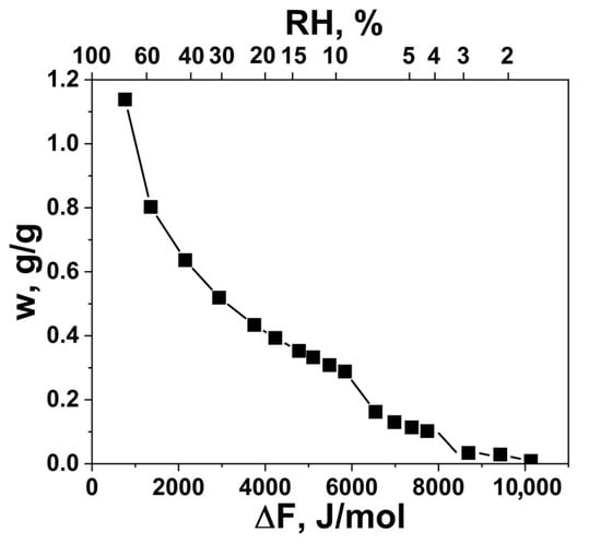
Figure 3.
Water sorption isotherm for the LiCl/silica composite in the coordinates of “uptake w—adsorption potential ΔF”. The appropriate RH values are presented for T = 22° C.
4. Mathematical Modelling
4.1. Model Description
The primary analysis of the VentireC unit is made by utilizing a mathematical model developed and verified in [28]. A single DCHE, which is a fin-tube heat exchanger coated with the LiCl/silica composite, is shown in the 3D Cartesian coordinate system (Figure 4). The geometrical parameters of this DCHE are presented in Table 2. Air flows between fins along the long side of the DCHE parallel to the x-axis. The heat exchanger is divided into control volumes (A–A in Fig. 4, Table 2). The numerical analysis is based on the following assumptions:
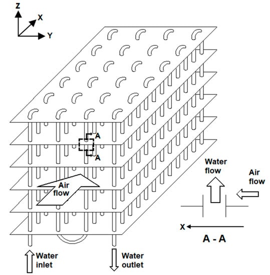
Figure 4.
Schematic diagram of the considered DCHE and the selected control volume.
Table 2.
Geometrical parameters of the modelled DCHE.
- The flow of air is one-dimensional, and the pressure drop is negligible.
- The thermal resistance in the sorbent coating is neglected, and the temperatures of the metal support and adsorbent in the same control volume are equal.
- The adsorbed heat released in the sorbent coating is transferred to the air flux by convection.
The energy balance of the air in the control volume can be written as:
The left side of the equation is the energy storage term. The first term on the right side stands for the net energy brought by the flow, and the second term shows the energy change caused by the heat convection.
Similarly, the energy balance equation of water is:
The energy balance of the DCHE can be described as:
The left side of the equation is the specific heat stored in the DCHE and the adsorbed water. The first and second terms on the right side refer to convection heat flow in the air and water sides. The third term refers to the sorption or desorption heat, and the last term refers to the transfer of sensible vapour heat connected with sorption or desorption.
The mass balance of water in the air can be described as:
Here, the left side refers to the water storage in the control volume. The first term on the right shows the net water brought about by the air flow. The second term represents water gain due to convection mass transfer.
The mass balance in the adsorbent can be derived as:
The left side refers to the mass change inside the adsorbent in the control volume; the right side refers to the mass gain from convection mass transfer.
Six values should be found, namely, Ta, TDCHE, Tw, Xa, Xad, and w, but only five balance equations are presented. Thus, the equilibrium relationship between w and Xad was used as the missing condition to solve the system. The isotherm of water sorption on the LiCl/silica composite was used to obtain a link between water vapour sorption capacity and adsorption potential. One can directly obtain from this curve the moisture content Xad as a function of water uptake w.
The initial and boundary conditions can be written as follows:
The system of Equations (1)–(11) is solved by means of the backward finite difference scheme for all control volumes with a time step of 0.02 s.
Three possible scenarios were modelled and compared:
- Latent heat transfer from one DCHE to another oneis fast; thus, the temperatures of the considered DCHE (adsorbent + HEx metal) and air are equal and constant
- There is no removal of latent heat; this heat is entirely released in the specified DCHE and causes a rise in temperature of adsorbent, metal, and air
- There is no latent heat removal, and the heat capacity of the HEx metal is assumed to be zero.
Case 1 corresponds to an ideal VentireC system, where the whole heat generated during water sorption in DCHE1 is quickly transferred to DCHE2. The system “DCHE + air” is isothermal; its temperature remains constant and equals the indoor air temperature Tin = 22 °C (line 1–2’ in Figure 2). Case 3 simulates an ideal Ventireg unit/process, in which the sorption/desorption stage is close to isenthalpic (line 1–2 in Figure 2). The latent heat released during water sorption is fully turned into sensible heat, which causes augmentation of the adsorbent and air temperatures. The main aim of the modelling is a comparison of cases 1 and 3 to evaluate a quantitative scale of the performance improvement due to latent heat removal (VentigeC).
Case 2 represents an advanced Ventireg unit: there is no heat transfer from one adsorbent bed to another one; however, the bed itself is the DCHE (Figure 4) instead of the traditional granulated bed. As mentioned above, the obvious advantage of this improved bed is lower hydrodynamic resistance and smaller electric power consumption for air blowing. Here, the effect of the specific heat of the HEx metal on the unit performance is studied. The HEx can partially absorb the latent heat released during adsorption.
One hundred working cycles were modelled for the three cases, staring from the dry sorbent state. The duration of the sorption and desorption stages was 2000 s. The inlet (room) air temperature during the sorption stage was fixed at 22 °C, and its humidity at RH 50%. Sensible heat was stored and released in the HS beds in the same way for cases 1–3; therefore, it was out of the analysis. For the three cases, the efficiency of heat regeneration in the HS bed is assumed to be 100%; thus, the inlet air temperature for the desorption stage equals 22 °C. The inlet humidity for the desorption stage RH = 3.8%, which corresponds to X = 0.61 g/m3 (Table 1).
4.2. Comparison of Various Scenarios
For all cases, after 55–60 cycles, the steady-state regime is set; thus, the mass of water caught during sorption is equal to the mass of water released during desorption (not presented). For case 1, imitating the ideal VentireC process, at the beginning of the sorption stage, the humidity ratio X of the outlet air equals 1.5 g/kg (Figure 5a). In the course of sorption, this ratio gradually increases to 2.0 g/kg. In the conventional Ventireg process (case 3), the humidity ratio jumps to 4.5 g/kg in 700 s after the beginning stage (Figure 5a) and then remains almost constant. This happens because, during the first 200 s of sorption, the isenthalpic conditions lead to an increase in temperature of the adsorbent and air by 11 °C—means up to 33 °C (Figure 5b). The dehumidification performance in case 2 is better than case 3, but worse than case 1 (X gradually increases from 1.6 to 3.6 g/kg during the sorption stage). The sorbent temperature increases due to latent heat release, however, only by 4 °C, because a part of the sorption heat is spent on heating the metal HEx. Thus, employing an Ad bed with inert thermal mass (case 2) instead of the common Ad bed (case 3) can be a way to enhance the dehumidification efficiency of the Vernireg unit.
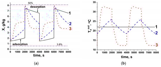
Figure 5.
Humidity ratio X (a) and temperature Taout (b) of the outlet air for steady-state cycles. Horizontal lines in Figure (a) indicate the humidity ratio of the inlet air during adsorption (RH 50%) and desorption (RH 3.8%).
The X-value of the outlet air obtained for the VentireC system (1.5–2.0 g/kg) corresponds to the dew point T3 = −10.7 to −7.5 °C, which is somewhat lower than T3 in Western Siberia (Table 1). The RH of the outlet air varies from 9% to 12% during the dehumidification stage, which is higher than RH, wherein LiCl/silica sorbs water vapour (<3%, Figure 3). Thus, during the process, equilibrium is not achieved, probably due to short contact time of air with the sorbent. To improve dehumidification performance, the parameters of the process (air flow rate) or DCHE geometry (the HEx length and/or the distance between fins) have to be changed (see Section 4.3).
Similar trends were observed for the desorption stage (Figure 5a). The performance of case 1 is better than that of cases 2 and 3: the VentireC unit manages to maintain X = 7.4 to 6.6 g/kg (Figure 5a) for the inflowing air flux. This corresponds to RH 40–45% at 22 °C, which meets the required value of 40–60% for indoor humidity [26]. Under the same conditions for cases 2 and 3, X drops from 7.9 to 4.7 and 3.7 g/kg, respectively, for 2800–4000 s. The initial water content in the outlet air for cases 2 and 3 is somewhat higher than that for case 1. This is because the adsorbent and HEx are overheated to 26 °C and 33 °C for cases 2 and 3 in the preceding adsorption stage, which promotes water desorption. However, the air temperature rapidly falls to 18 °C and 12 °C (for cases 2 and 3) because of the heat consumed for water desorption. The effect of the sorbent cooling in case 2 is smaller than that for case 3 because the sensible heat stored in the metal Hex during previous sorption partially contributes to the desorption.
Integration of the humidity ratio X of the outlet air during the adsorption stage shows that the new VentireC unit (case 1) adsorbs 78% of the moisture entering the DCHE bed (which leads to 83% of moisture recuperation). This value is much higher than that obtained for cases 2 and 3 (67% and 50%) at the same adsorbent mass. This reduction is due to significant heating of the adsorbent (Figure 5b), which restricts further adsorption. Thus, in terms of moisture recuperation, the new VentireC (case 1) is more efficient than the standard (case 3) and advanced (case 2) Ventireg units.
4.3. Effects of HEx Geometry and Air Flow Rate
To verify the influence of the process parameters and DCHE geometry on VentireC performance, the air flow rate (Table 3, cases 1_2 and 1_3) and distance between DCHE fins (Table 3, case 1_1) were varied. Other parameters are the same as for case 1, including HEx size, X x Y x Z.
Table 3.
Parameters of the process and DCHE.
At a larger flow rate, both drying and moisturizing performances get worse because the process air is in contact with the adsorbent for a shorter time (Table 3). In the adsorption stage, humidity ratio increases from 1.5–2.0 g/kg for reference case 1 to 2.0-2.2 and 2.6-3.2 g/kg for cases 1_2 and 1_3, respectively (Figure 6). The fraction of water removed from the room air reduces to 73% and 62% for 1_2 and 1_3, as compared to the reference 75%. For the desorption stage, humidity ratio in the returned air is lower (6.6–6.4 and 5.6–6.1 g/kg for cases 1_2 and 1_3) than that for reference case 1 (7.4–6.6 g/kg). These values correspond to the RH of outflow air 41–39% and 37–33%, which is lower than the required RH = 40–60%.
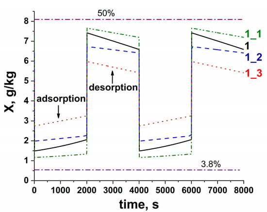
Figure 6.
Humidity ratio X for the steady-state VentireC cycles. Horizontal lines—humidity ratio of the inlet air during sorption (RH 50%) and desorption (RH 3.8%).
On the contrary, VentireC performance can be improved by a decrease in gap between the fins inside the DCHE. Thus, the dehumidification degree during the adsorption stage increases to 84% for DCHE, in which the distance is halved (case 1_1). The humidity ratio falls to 1.2–1.35 g/kg, which corresponds to a dew point of −13.2 to −12.0 °C. This DCHE can be used in colder climates. The humidification also gets better: absolute humidity is maintained at 7.65–7.2 g/kg, which corresponds to the acceptable RH 42–47% at 22 °C. This performance improvement is due to the fact that with smaller gap between the fins, the number of fins and, consequently, the mass of adsorbent loaded into the DCHE is enlarged. Even if air residence time becomes somewhat shorter (Table 3), overall dehumidification/humidification efficiency increases. The improvement can also be partially due to a shorter distance for water vapour to diffuse to the adsorbent coating, because the air flow between the fins is laminar (Reynolds number Re = 37 for case 1_1, Table 3).
5. Conclusions
This research work addresses a new adsorption method for heat and moisture recuperation in ventilation systems in cold climates. An advanced VentireC approach employing two thermally coupled heat exchangers, which operate in opposite modes, is proposed and described. Mathematical simulation of humidity exchange in three VentireC and Ventireg units under Western Siberia climatic conditions was conducted. The composite LiCl/silica gel is used as a solid sorbent.
The results of the mathematical modelling show that the ideal (isothermal) VentireC system, which corresponds to highly efficient heat transfer between two thermally coupled DCHEs, demonstrates better moisture regeneration than the common Ventireg process. VentireC offers the following: i) inflow air humidity maintained at a comfortable level of 40–45%, and ii) freezing of moisture in unit outlets in outdoor temperatures above −12 °C (case 1_1) is avoided. At a lower outdoor temperature, better dehumidification can be achieved by reducing the gap between the HEx fins or/and increasing the HEx length, hence obtaining an ideal contact time between air and the adsorbent.
Author Contributions
Conceptualization, L.G. and Y.A.; methodology, L.G.; mathematical modelling, T.Y.; results analysis, I.G.; data curation, W.W.; writing—original draft preparation, I.G., L.G.; writing—review and editing, Y.A.; supervision, L.G.; project administration, L.G. and T.G.; funding acquisition, L.G. and T.G. All authors have read and agreed to the published version of the manuscript.
Funding
This work was supported by the Russian Foundation for Basic Researches (joint RFBR-NSFC project no. 19-53-53007 GFEN-a).
Conflicts of Interest
The authors declare no conflict of interest.
Nomenclature
| A | area, m2 |
| Cp | specific heat at constant pressure, J/(kg K) |
| ΔF | adsorption potential, J/mol |
| ΔHad | adsorption enthalpy, J/kg |
| H | coefficient of heat convection, W/(m2 K) |
| Ky | coefficient of mass convection, kg/(m2 s) |
| L | thickness, mm |
| M | mass flow rate, kg/s |
| M | mass, kg |
| Q | heat, J |
| RH | relative humidity, % |
| T | time, s |
| T | temperature, K |
| V | volume, m3 |
| w | water uptake, g/g |
| X | moisture content, g/kg |
| Ρ | density, kg/m3 |
| Subscript | |
| In | Indoor |
| Out | Outdoor |
| Superscript | |
| In | Inlet |
| Out | Outlet |
| A | dry air |
| Ad | Adsorbent |
| Al | Aluminium |
| Cu | Copper |
| I | Initial |
| V | water vapor |
| W | liquid water |
| Abbreviations | |
| Ad | Adsorbent |
| CSPM | Composite sorbents “Salt in Porous Matrix” |
| DCHE | desiccant coated heat exchanger |
| Hex | heat exchanger |
| HRV | heat recovery ventilator |
| HS | heat storing |
| HTF | heat transfer fluid |
References
- EA-RETD; de Vos, R.; Sawin, J. Heating and Cooling Policies. In READy Renewable Energy Action Deployment; Elsevier: Amsterdam, The Netherlands, 2013; pp. 115–135. [Google Scholar]
- Heat Energy and District Heating in Russia in 2015–2016 Years. Ministry of Energy of the Russian Federation, Russian Energy Agency Federal State Institution, Information Analytical Report. Available online: https://minenergo.gov.ru/node/10850 (accessed on 16 March 2020).
- Filippov, S.P.; Dil’man, M.D.; Ionov, M.S. The Optimum Levels of the Thermal Protection of Residential Buildings under Climatic Conditions of Russia. Therm. Eng. 2013, 60, 841–851. [Google Scholar] [CrossRef]
- Mardiana-Idayu, A.; Riffat, S.B. Review on heat recovery technologies for building applications. Renew. Sustain. Energy Rev. 2012, 16, 1241–1255. [Google Scholar] [CrossRef]
- Ahmed, R.; Appelhoff, J. Frost-protection measures in energy recuperation with multiple counterflow heat exchangers. Rehva 2013, 5, 37–40. [Google Scholar]
- Beattie, C.; Fazio, P.; Zmeureanu, R.; Rao, J. Experimental study of air-to-air heat exchangers for use in arctic housing. Appl. Therm. Eng. 2018, 129, 1281–1291. [Google Scholar] [CrossRef]
- Glaznev, I.; Alekseev, V.; Salnikova, I.; Gordeeva, L.; Shilova, I.; Elepov, B.; Aristov, Y. ARTIC-1: A New Humidity Buffer for Showcases. Stud. Conserv. 2009, 54, 133–148. [Google Scholar] [CrossRef]
- Aristov, Y.I.; Mezentsev, I.V.; Mukhin, V.A. A new approach to regenerating heat and moisture in ventilation systems. Energy Build. 2008, 40, 204–208. [Google Scholar] [CrossRef]
- Alonso, M.J.; Liu, P.; Mathisen, H.M.; Ge, G.; Simonson, C. Review of heat/energy recovery exchangers for use in ZEBs in cold climate countries. Build. Environ. 2015, 84, 228–237. [Google Scholar] [CrossRef]
- Cerrah, E.; McCague, C.; Bahrami, M. Sorbent based enthalpy recovery ventilator. Energy Build. 2020, 211, 109755. [Google Scholar] [CrossRef]
- Shimooka, S.; Oshima, K.; Hidaka, H.; Takewaki, T.; Kakiuchi, H.; Kodama, A.; Kubota, M.; Matsuda, H. The evaluation of direct cooling and heating desiccant device coated with FAM. J. Chem. Eng. Jpn. 2007, 40, 1330–1334. [Google Scholar] [CrossRef]
- Ge, T.S.; Dai, Y.J.; Wang, R.Z.; Peng, Z.Z. Experimental comparison and analysis on silica gel and polymer coated fin-tube heat exchangers. Energy 2010, 35, 2893–2900. [Google Scholar] [CrossRef]
- Zhao, Y.; Ge, T.S.; Dai, Y.J.; Wang, R.Z. Experimental investigation on a desiccant dehumidification unit using fin-tube heat exchanger with silica gel coating. Appl. Therm. Eng. 2014, 63, 52–58. [Google Scholar] [CrossRef]
- Tsujiguchi, T.; Osaka, Y.; Kumita, M.; Kodama, A. Adsorption–desorption behavior of water vapor and heat-flow analysis of FAM-Z01-coated heat exchanger. Int. J. Refrig. 2019, 105, 3–10. [Google Scholar] [CrossRef]
- Freni, A.; Bonaccorsi, L.; Calabrese, L.; Caprì, A.; Frazzica, A.; Sapienza, A. SAPO-34 coated adsorbent heat exchanger for adsorption chillers. Appl. Therm. Eng. 2015, 82, 1–7. [Google Scholar] [CrossRef]
- Cui, S.; Qin, M.; Marandi, A.; Steggles, S.; Wang, S.; Feng, X.; Nouar, F.; Serre, C. Metal-Organic Frameworks as advanced moisture sorbents for energy-efficient high temperature cooling. Sci. Rep. 2018, 8, 15284. [Google Scholar] [CrossRef]
- Munz, G.M.; Bongs, C.; Morgenstern, A.; Lehmann, S.; Kummer, H.; Henning, H.-M.; Henninger, S.K. First results of a coated heat exchanger for the use in dehumidification and cooling processes. Appl. Therm. Eng. 2013, 61, 878–883. [Google Scholar] [CrossRef]
- Ge, T.S.; Dai, Y.J.; Wang, R.Z. Performance study of desiccant coated heat exchanger air conditioning system in winter. Energy Convers. Manag. 2016, 123, 559–568. [Google Scholar] [CrossRef]
- Tu, Y.D.; Wang, R.Z.; Ge, T.S. New concept of desiccant-enhanced heat pump. Energy Convers. Manag. 2018, 156, 568–574. [Google Scholar] [CrossRef]
- Kubota, M.; Hanaoka, N.; Matsuda, H.; Kodama, A. Dehumidification behavior of cross-flow heat exchanger type adsorber coated with aluminophosphate zeolite for desiccant humidity control system. Appl. Therm. Eng. 2017, 122, 618–625. [Google Scholar] [CrossRef]
- Chai, S.; Sun, X.; Zhao, Y.; Dai, Y. Experimental investigation on a fresh air dehumidification system using heat pump with desiccant coated heat exchanger. Energy 2019, 171, 306–314. [Google Scholar] [CrossRef]
- Shkatulov, L.G.; Gordeeva, I.S.; Girnik, H.; Huinink, Y.I.; Aristov. Novel adsorption method for moisture and heat recuperation in ventilation: Composites “LiCl/matrix” tailored for cold climate. Energy 2020. submitted. [Google Scholar]
- Jiang, Y.; Ge, T.S.; Wang, R.Z.; Hu, L.M. Experimental investigation and analysis of composite silica-gel coated fin-tube heat exchangers. Int. J. Refrig. 2015, 51, 169. [Google Scholar] [CrossRef]
- Gordeeva, L.G.; Aristov, Y.I. Composites “salt inside porous matrix” for adsorption heat transformation: A current state of the art and new trend”. Int. J. Low Carbon Technol. 2012, 7, 288–302. [Google Scholar] [CrossRef]
- Aristov, Y.I. Nanocomposite Sorbents for Multiple Applications; Jenny Standford Publishing: Singapore, 2020; 420p, ISBN 9789814267502. [Google Scholar]
- Sanitary and Epidemiological Rules and Regulations SanPin 2.1.2.2645-10. Available online: https://base.garant.ru/12177273/f52b32b623103013c77c8c319c288f45/#block_12000 (accessed on 16 March 2020).
- Grekova, A.; Gordeeva, L.; Sapienza, A.; Aristov, Y. Adsorption transformation of heat: The applicability in various climatic zones of the Russian Federation. Appl. Sci. 2019, 9, 139. [Google Scholar] [CrossRef]
- Ge, T.S.; Dai, Y.J.; Wang, R.Z. Performance study of silica gel coated fin-tube heat exchanger cooling system based on a developed mathematical model. Energy Convers. Manag. 2011, 52, 2329–2338. [Google Scholar] [CrossRef]


© 2020 by the authors. Licensee MDPI, Basel, Switzerland. This article is an open access article distributed under the terms and conditions of the Creative Commons Attribution (CC BY) license (http://creativecommons.org/licenses/by/4.0/).