Article

A Numerical Study on the Performance of Ground Heat Exchanger Buried in Fractured Rock Bodies

1
College of Mines, Guizhou University, Huaxi District, Guiyang 550025, China
2
Key Laboratory of Deep Coal Resource Mining, China University of Mining and Technology, Xuzhou 221116, China
*
Author to whom correspondence should be addressed.
Energies 2020, 13(7), 1647; https://doi.org/10.3390/en13071647
Submission received: 1 February 2020 / Revised: 17 March 2020 / Accepted: 30 March 2020 / Published: 2 April 2020
(This article belongs to the Special Issue Computational Geothermal Energy Applications)

Abstract

:
The ground source heat pump (GSHP) is receiving increasing attention due to the global trend of energy-saving and emission reduction. However, projects with ground heat exchangers (GHEs) buried in fractured rock bodies are scarce, and the impacts of water flow in fractures on the system performance are short of detailed investigations. In this paper, a three-dimensional model was built to study the temperature distribution underground and the relative performance of heat pumps and GHEs influenced by groundwater flow in fractures. Three factors including fluid flow velocities in fractures, the number of fractures and the distributions of fractures were taken into consideration, a range of indicators including outlet temperature of GHEs, mean temperature of “Energy Storage Rock Body” (ESRB) and heat injection rate per unit length were examined. It was found that the heat injection rate per unit length of a U-pipe in fractured rock body could be up to 78.83% higher than that of a U-pipe in integrated rock. Likewise, the coefficient of performance of cases with fractures was identified to be up to 4.50% higher than the integrated rock case. In addition, differently distributed fractures also have different impacts on the heat transfer efficiency of heat pumps and GHEs.

1. Introduction

The building sector is one of the largest energy-consuming sectors after the industry and transportation sectors, and also a significant contributor to greenhouse gas emissions [1,2]. It occupies 20–50% of whole energy consumption worldwide [3] and 47% in China [4]. Renewable energy resources appear to be a prime alternative energy resources for the purpose of curbing energy consumption and emissions. As a foremost means to efficiently utilize the shallow thermal energy to achieve energy saving, ground source heat pump (GSHP) systems are receiving more attention. Special plans have been rolled out in many nations for utilizing shallow geothermal energy to alleviate the carbon emission. As a consequence of more GSHPs installed in different regions, impacts of various geological conditions, including fractured rock bodies filling with groundwater, on the performance of GSHPs need to be well evaluated.
Although GSHP systems have been adopted in various areas around the world, only a few projects have been established in rock formations where fractures, caves, and underground rivers are developed for groundwater migrating. A piece of evidence is that most GSHPs built in China are distributed in the north and east regions [5] instead of south and southwest where the Karst formations are developed, and the groundwater might be a potential benefit to accelerate the heat from indoor cooling load dissipating in the carbonate bedrock [6]. Fractured rock bodies, including but not limited to those in Karst regions, are extensively distributed. It is inevitable to investigate heat transfer characteristics in diverse geologic features involving fractured rock bodies to promote the application of the GSHP all over the world due to the strong reliance of GSHP performance on the groundwater flow regime [7], and one of the priorities is how the groundwater flow in rock fractures influences the relative performance of ground heat exchangers (GHEs) and heat imbalance in the rock formation over long term operation.
However, most previous studies about GSHP were related to the impacts of groundwater flow in pores of the formation or seepage. Through a 2D finite element model, Meng et al. [7] compared seasonal coefficient of performance (COP) of GSHP in terms of different flow rates, and it was concluded that with the groundwater flow velocity increasing, heat transport transforms from conduction-dominated to advection-dominated, and a moderate increase of groundwater flow has a significant effect on the energy performance. Hua et al. [8] compared the temperature distributions near the GHE with/without seepage by a 2D model, and identified that the soil temperature near the GHE recovers quickly when the groundwater seepage velocity is greater than 5 × 10⁻⁶ m/s. Hecht-Méndez et al. [9] found that the temperature difference between operation strategies with and without load-optimized is closely related to the groundwater flow velocity, the higher groundwater flow velocity, the more advective heat is supplied, the temperature decrease difference with and without the optimized strategies are more noticeable. You et al. [10] also compared the temperature distributions around the energy piles with and without groundwater flow, which alleviated the soil temperature decrease near the energy piles in the heating season, but also led to a much higher heat exchange rate of the energy piles. It was also identified that the drop of COP of the heat pump during the case with groundwater flow was significantly slower than that without groundwater flow.
On the basis of those extensive 2-D simulation researches, a few scholars started to establish 3-D simulations incorporating GHEs performance. Li et al. [11] used 3-D models to study the heat transfer ability over the long and short term with and without seepage, indicating the soil temperature is more stable with the condition of ground seepage. Tang and Nowamooz [12] evaluated the performance of the GHEs installed in sand and clay in terms of 15 factors entailing various groundwater flow velocities in porous media, which has little effect on the heat pump COP. Hein et al. [13] studied the influences of different Darcy velocities on recovery efficiency of the shallow geothermal reservoir and pointed out that, as the Darcy velocity increases, the recovery ratio increases in an exponential manner until it approaches a turning point. Lei et al. [14] built a 3-D model to study the temperature field around pipes buried in the ground with various hydraulic conditions, they studied the temperature distribution between two pipes with a spacing of 9 m, and found the heat concentrated 1–2 m away from the individual buried pipes. Zhang et al. [15,16] carried out mathematical models to study the heat transfer of GHEs with 3-D groundwater seepage at various velocity components. They evaluated the heat transfer on the XOY, XOZ, and YOZ planes at different angles, and established that the angles between the velocity and axis play an important role in the influence of groundwater seepage, directly relating to the performance.
These aforementioned studies mostly focused on the influences of groundwater in pores of soil and rocks, where the groundwater flow was basically depicted by the Darcy’s Law. However, there are few pieces of researches about the GHEs performance influenced by fracture water flow in rock formations. In Karst terrains, not only large amounts of fractures extensively distribute, but also various forms of groundwater sources exist, including conduit water, confined water, and water in porous media [17,18]. It is obvious that the hydraulic conditions in Karst areas or other fractured rock formations are more complicated, and the corresponding heat transfer mechanism, as well as their impacts to the relative performance of GHEs and heat pumps remain unclear. Zeng et al. [6,19] mentioned that the outlet temperature difference of two GHEs installed apart 2 m during an on-site test was probably caused by the Karst groundwater flow passing by one of the two individual U-pipes, but no more extended investigations.
In this work, based on known characteristics of fractured formations, a numerical model was carried out to evaluate the heat transfer performance of heat pump and GHEs buried in rock formations containing horizontal and vertical fractures, as well as the heat imbalance potential in the rock formation. Three influencing factors, embracing water flow velocities in fractures, the number of fractures and the distributions of fractures, were investigated. The temperature field in the vicinity of GHEs and outlet temperature of GHE of different cases were collected, and corresponding COP values and heat injection rate per unit length were derived for assessing the heat transfer performance of GHEs influenced by diverse fractures and hydraulic conditions. This study presents a detailed investigation into the heat transfer mechanism between GHEs and the host fractured formation, and identifies the influencing extent of the above factors. The model can be used by designers and operators to more accurately evaluate the risk of heat imbalance and the performance of GHEs and GSHPs, respectively.

2. Methodology

2.1. Mathematical Model

2.1.1. Hydraulic Transfer in Porous Media

The Darcy’s law equation visualizes the hydraulic potential field by considering the difference in both pressure and elevation potential from the start to the end points of the flow line, the equation is given as:
u = κ μ ( p + ρ g D )
where u (m/s) is the Darcy velocity or specific discharge vector, κ (m2) is the permeability of the porous medium, μ (Pa∙s) is the fluid’s dynamic viscosity, ρ (kg/m3) is the fluid density, g (m/s2) is the magnitude of gravitational acceleration, and ∇D (dimensionless)is a unit vector in the direction over which the gravity acts.
The water flow in most small-size fractures still follows the Darcy’s Law. Parameters such as permeability and porosity in fractures are different from those of matrix. The fracture flow equation uses the tangential derivatives of Darcy’s law to define the flow along the interior boundaries representing fractures within a porous block:
q f = κ f μ d f ( T p + ρ g T D )
where q f (m2/s) is the volume flow rate per unit trace length in the fracture, κ f (m2) is the fracture’s permeability, df (m) is the aperture or fracture thickness, T denotes the gradient operator restricted to the fracture’s tangential plane, p (Pa) is the pressure, and D (dimensionless) represents the vertical coordinate.

2.1.2. Heat Transfer in Porous Media and in U-Pipe

The energy balance equation in porous media is given as:
ρ m C P T t + ρ C P u T + ( k T ) = Q
where ρm (kg/m3) is the porous media’s density, C P (J/kg·K) is the specific heat capacity at constant pressure, T (K) is the temperature, t (s) is time, u (m/s) is the velocity vector, k (W/m∙K) is the thermal conductivity, and Q (W/m3) is the heat source other than viscous dissipation.
The heat transfer mechanism among heat carrying flow, U-pipe and host rock include conduction, advection, and transfer through walls based on the principle of energy conservation, the energy equation for an incompressible fluid flowing in a pipe is given as:
ρ f A C P T t + ρ f A C P u T = A k T + f D ρ f A 2 d h | u | 3 + Q g + Q W a l l
where ρ f (kg/m3) is the fluid density, A (m2) is the pipe cross section area available for flow, the second term (W/m) on the right hand side corresponds to friction heat dissipated due to viscous shear (W/m), f D (dimensionless) is the Darcy friction factor, d h (m) is the mean hydraulic diameter, Q g (W/m) represents a general heat source, and Q W a l l (W/m) represents external heat exchange through the pipe wall.
The heat transfer from the surroundings into the pipe is given by:
Q W a l l = ( h Z ) e f f ( T e x t T )
where ( h Z ) e f f is an effective value of the heat transfer coefficient h (W/m2∙K) times the wall perimeter Z (m) of the pipe, and Text (K) is the external temperature outside of the pipe.

2.1.3. Heat Pump COP

COP of the heat pump in this paper is the cooling mode coefficient of performance and defined as the ratio between the delivered cooling load (kW) and the input electric power of heat pump (kW) [20]. The COP value varies linearly with the carrying fluid outlet temperature [13,21,22,23]. According to [12], an alternative equation can be used to determine the COP of a heat pump rather than using directly the carrying fluid outlet temperature to evaluate the GHE performance. In the following work, it is assumed that the same GCHP system was used in all different examined cases, and all COP values could be calculated by Equation (6), so the influences of considered factors on COP were compared on the same base. For the Dimplex SI 30TER+, the relation between the carrying fluid outlet temperature and the heat pump COP is given as [13]:
C O P = 0.12 T o u t + 8.6
where Tout (°C) is the outlet temperature of the U-pipe.

2.2. Geometric Model

The geometric model was designed based on real situations to serve the purpose of this study. The model contains different forms of fractures and is capable of comparing different cases on the same base.
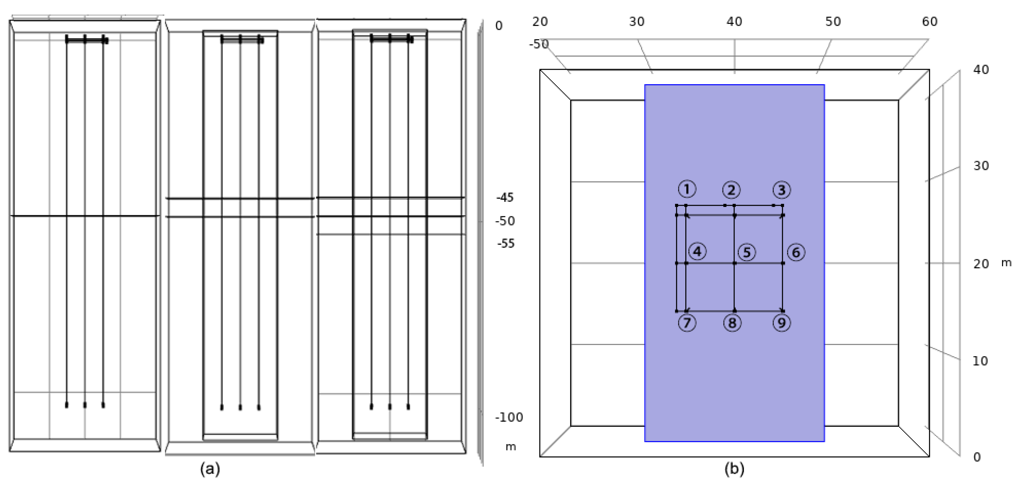
During operation, a U-pipe could be influenced by others around it, so the model contained 9 numbered U-pipes buried in heat exchange holes. The length of the depth of the heat exchange hole was assumed to be 100 m, and the spacing between holes was assumed to be 5 m, like most real projects. All simulations were carried out on a domain of 40 m × 40 m × 115 m in size with homogeneous properties (Figure 1). It was certified by an experimental simulation that this domain size is sufficiently large with no interfering with the model boundaries. At the top of the model, there is a horizontal pipe network with an individual inlet and outlet of carrying fluid respectively. In the middle of the model, a 20 m × 20 m × 110 m cuboid encompassing the 9 U-pipes was used to simulate the near field called the “energy storage rock body” (ESRB). In the study, the mean temperature of the ESRB was calculated to evaluate the level of heat imbalance, because the heat was mainly accumulated in the specific near-field volume containing the U-pipes. The heat exchange holes where the U-pipes were buried with backed filled materials of the original excavation.
Formations with diverse numbers of horizontal and vertical fractures were modeled in the study (Figure 2 and Figure 3):
  • No fracture (NF);
  • 1 horizontal fracture (H1);
  • 2 horizontal fractures (H2);
  • 3 horizontal fractures (H3);
  • 1 vertical fracture (V1);
  • 2 vertical fractures (V2);
  • 3 vertical fractures (V3).
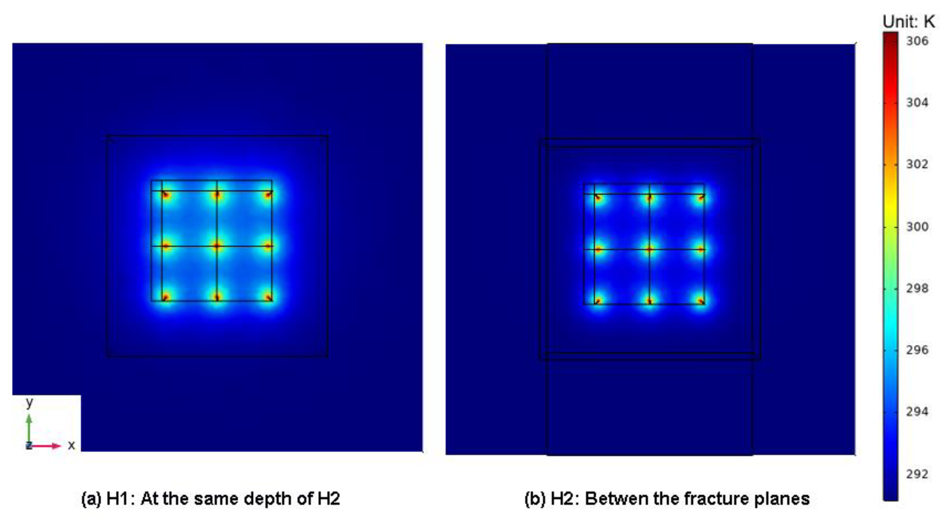
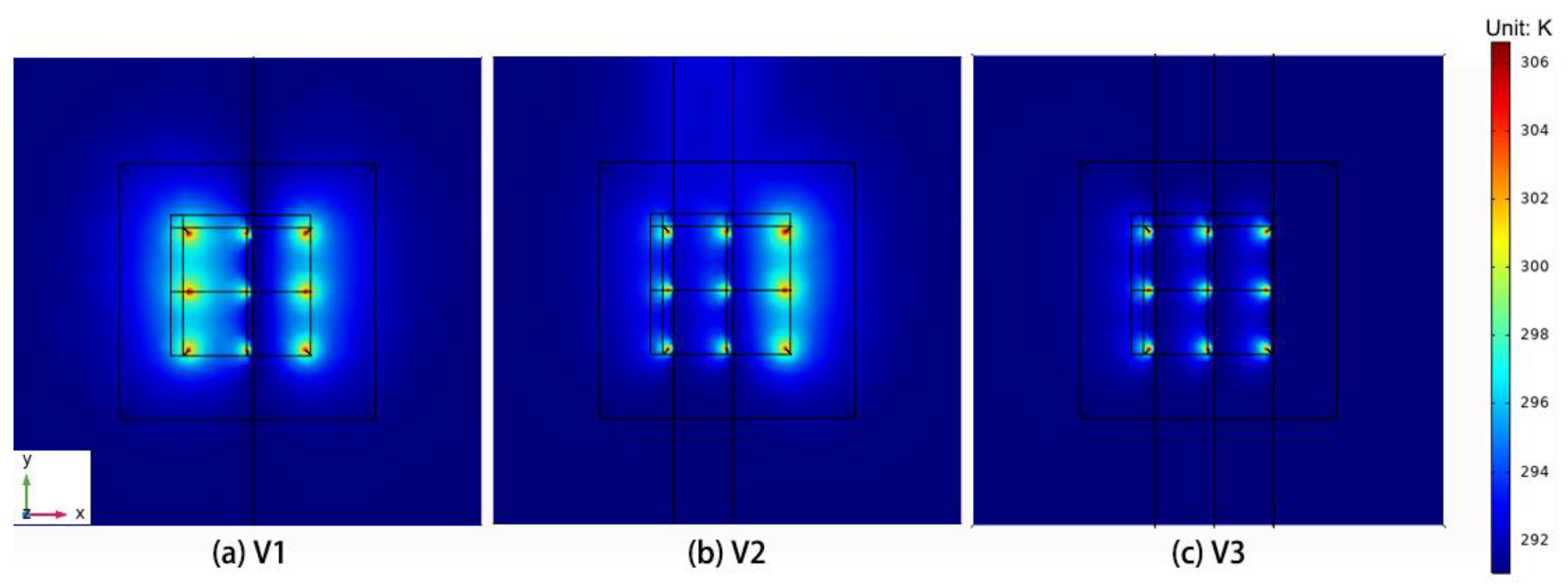
Figure 2 depicts all the horizontal fracture cases at the YOZ and XOY planes, and Figure 3 shows the Case V3 at those two planes (Cases V1 and V2 eliminated two and one fractures, respectively, and kept the middle one for obtaining the No.5 U-pipe’s performance in cases). Fractures in all cases shared the same size and same distance (5 m) between each other for the purpose of comparing consequences on the same base. Each vertical fracture was 0.5 m apart from the individual row of U-pipe as shown in Figure 3b.
In the following section, a validation work based on an on-site thermal response test (TRT) was first performed to assure the accuracy of the model above. Then, the effects of three factors (water flow velocities in fracture, numbers of fractures, and distributions of fractures) on the temperature field and performance of GHEs and the heat pump were evaluated. Firstly, the effect of different water flow velocities in one horizontal fracture was examined. Then, with a fixed fracture water flow velocity, different numbers of horizontal and vertical fractures were modeled correspondingly, and indicators of performance were obtained to compared with each other and especially with those of the no fracture scenario. These different simulated scenarios were based on the same geometric model, thermophysical properties, and operation mode.

3. Validation of the Numerical Framework

Before proceeding to further modeling, the proposed simulation approach, modules of software and control equations were validated by simulation work corresponding with a TRT conducted on the campus of Guizhou University in 2014. The on-site TRT was conducted by using a dual U-pipe heat exchanger to evaluate the applicability of GSHP for the university library.

3.1. Geometry Model of the On-Site TRT

It should be noted that the geometric model in the validation work is a simplification of the model in Section 2.2, because the TRT incorporated only one GHE. However, the heat transfer between the U-pipes and outside (porous matrix) is still governed by Equation (5) regardless of the number of U-pipes. Further, the fluid transfer in fractures is governed by Equation (2), which is modified from Darcy’s law. While the validation model employs Darcy’s law to calculate the porous flow. Therefore, the validation work proved the reliability of the model used in the following sections. The geometric GHE model of the TRT is shown in Figure 4.

3.2. Validation Results

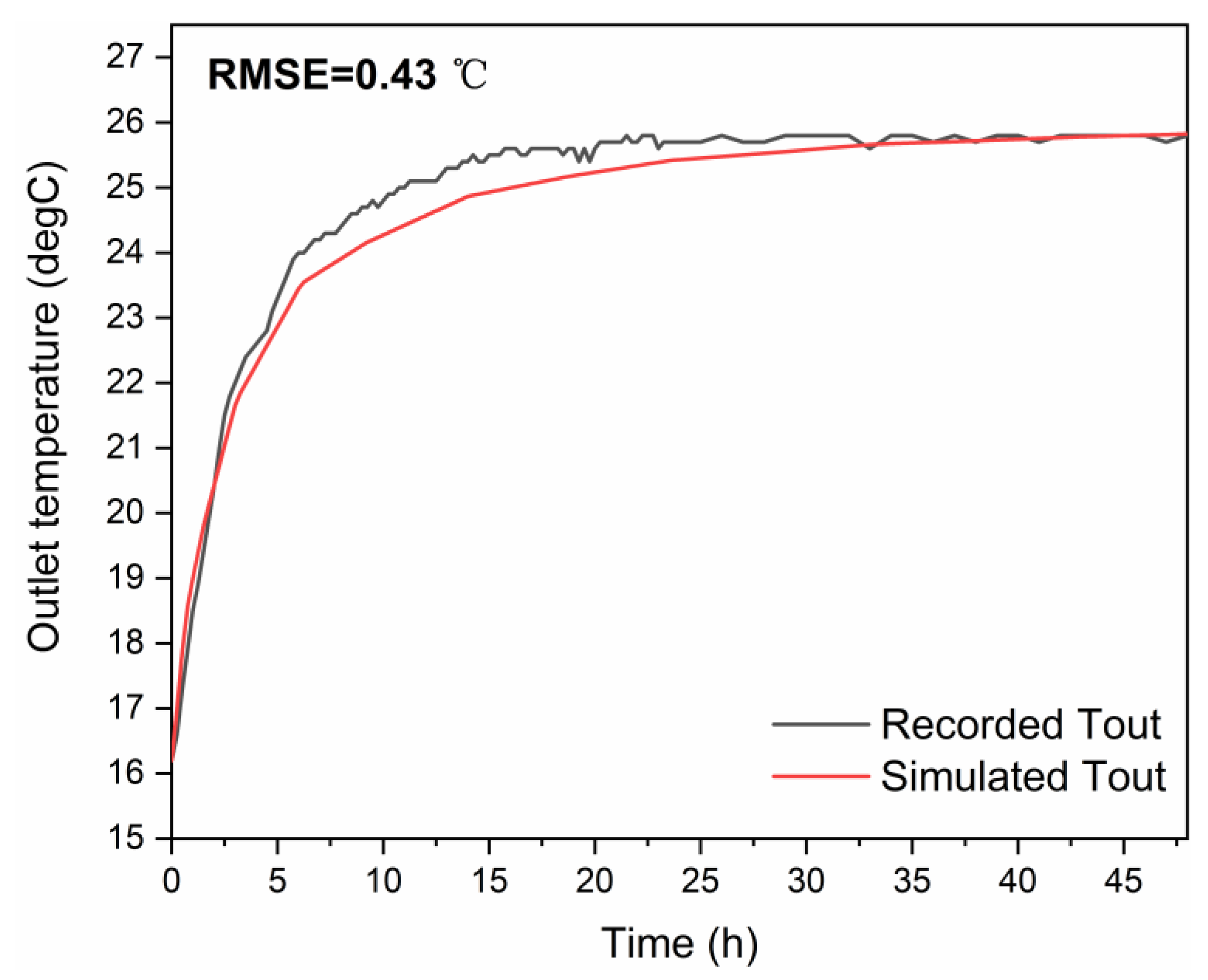
In the validating numerical simulation, the geometry of the model and input parameters were set the same as that of the field test listed in Table 1.The simulated results of the outlet temperatures were obtained after the unit running for 48 h and compared with the record from the field test (Figure 5). The root means square error (RMSE) was used for verification of the simulation accuracy:
R M S E = 1 n i = 1 n ( t r t s ) 2
where t r (°C) is the recorded outlet temperature of the TRT, t s (°C) is the simulated outlet temperature, and n is the number of the obtained data.
Figure 5 shows the comparison between the in-situ tested and simulated outlet temperatures by reporting the RMSE. The good agreement between the actual recorded data and the predicted data verifies the reliability of the proposed numerical framework and simulation approach to use in the following sections.

4. Results and Discussion

Three factors impacting heat imbalance in rock body and performances of GHEs and GSHPs were evaluated:
  • Different velocities of fluid flow in fractures,
  • Diverse numbers of fractures, and,
  • Distributions of fractures.
In order to evaluate the impact of fracture water flow more straightforwardly, an extreme situation was considered—the load was only in the cooling mode, which means heat was only injected into the ground but not extracted. This assumption also matches some real cases in the Karst region in South China, where the climate is subtropical. Through simulating, indicators of heat imbalance in rock body (temperature contours in rock formation and matrix mean temperature of ESRB) and indicators of performance (outlet temperature, heat pump COP, and heat injection rate per unit depth) were obtained. U-pipe No. 5 shown in Figure 1, Figure 2 and Figure 3 was selected to observe the impact on the heat injection rate per unit length. Referred and assumed parameters used in the simulation are listed in Table 2.

4.1. Velocity of Fluid Flow in Fractures

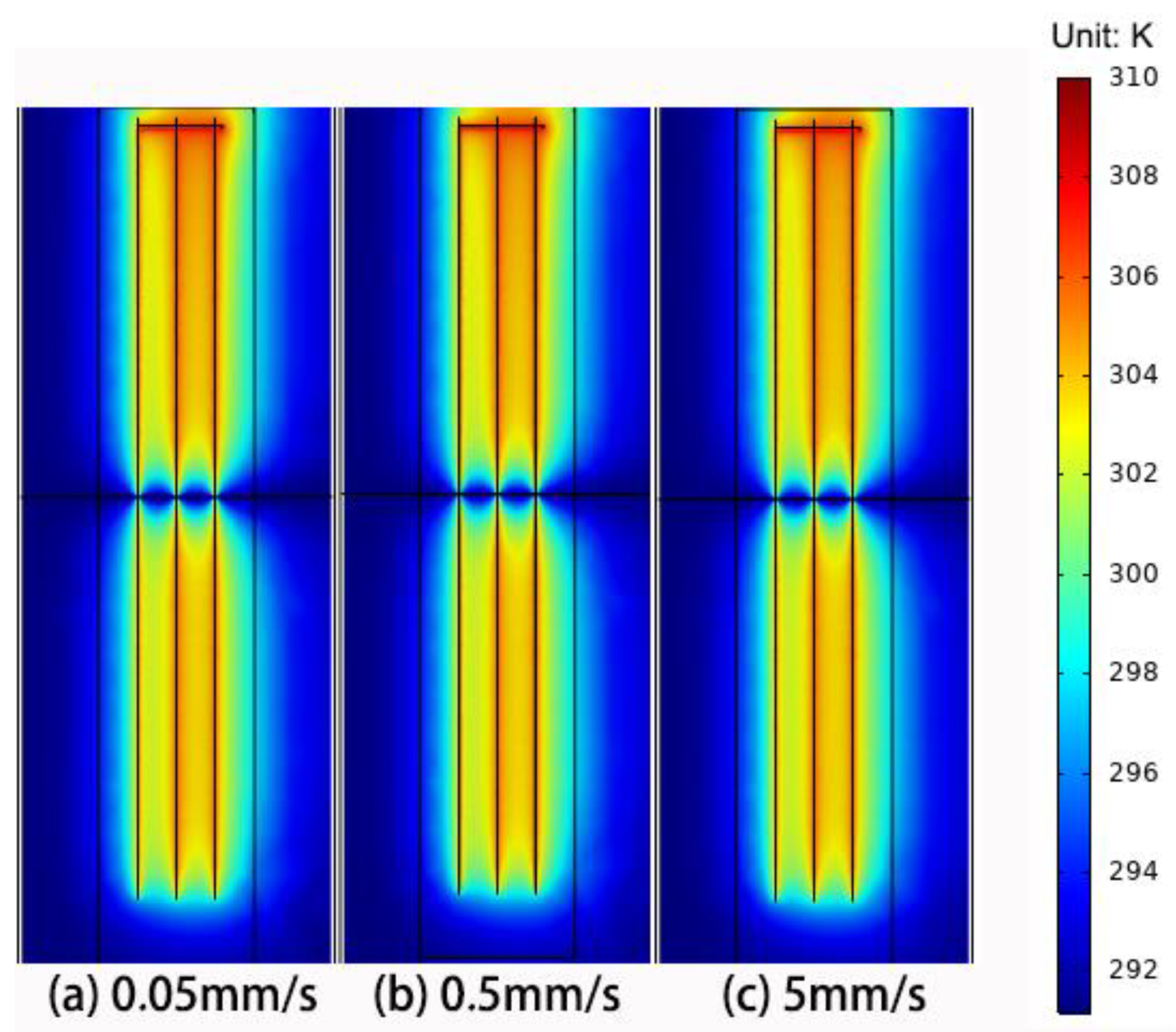
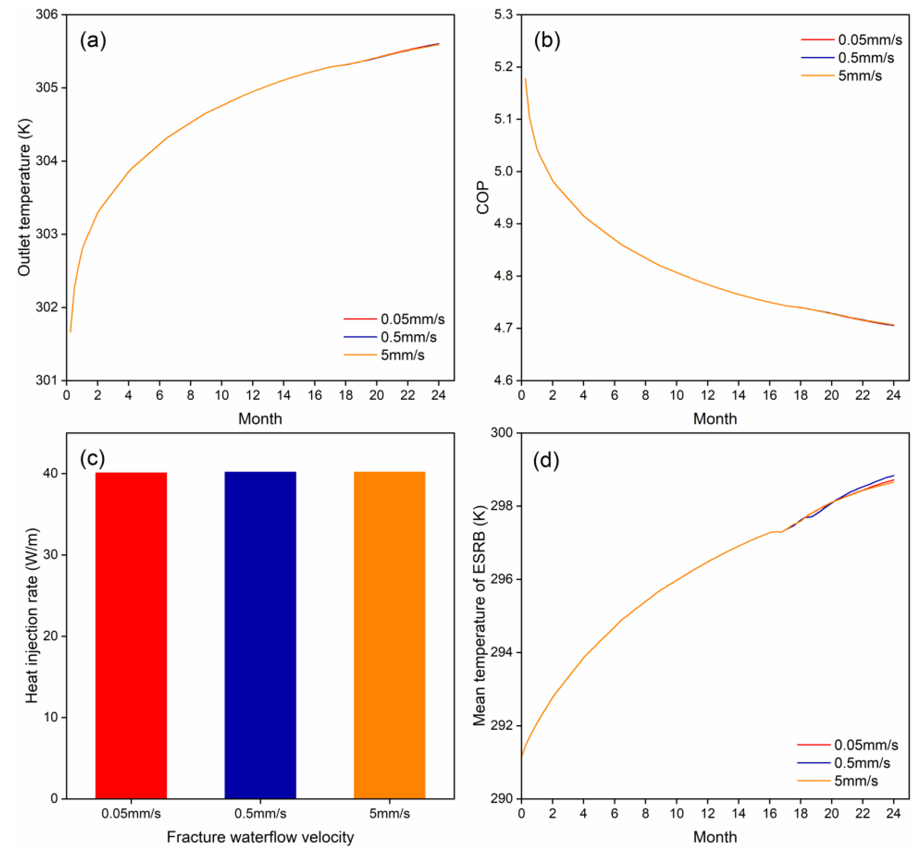
To investigate the influence of the velocity of fluid flow in a horizontal fracture, a 24-month continuous working simulation was carried out with three different velocities: 0.05 mm/s, 0.5 mm/s, and 5 mm/s. The specific temperature contours are shown in Figure 6, and graphs of other indicators are depicted in Figure 7.
Each contour in Figure 6 shows that various fluid flow velocities in fractures made no difference to the temperature distributions. It also can be established from Figure 7 that the influence caused by velocities to GSHP performance was limited, as the COP of the three scenarios shared identical curves and values. This phenomenon can be discussed by comparing it with the case of formation with pore water seepage. According to [8], heat accumulation could be neglected when the seepage velocity in the matrix is higher than a critical value of 5 × 10⁻⁶ m/s. This could also be true in the case of fracture water flow. In the modeling results in Figure 5, in the area immediately close to the fracture, heat accumulation was almost eliminated. This means that the modeled flow velocity range was above a critical value. It is worth noting that most field-measured velocities of fracture flow were within the modeled range (0.005–5 mm/s) [26]. Therefore, most fracture flows should be able to eliminate heat accumulation in areas immediately around fractures, and their effects on temperature and system performance should have little difference.

4.2. The Number and Distributions of Fractures

To evaluate the level of heat imbalance in the rock formation, as well as the relative performance of heat pump and the U-pipe heat exchanger, simulations of 2 operation years (24 months) in the subtropical region were conducted by a different pattern. That is, in each operation year, the first 5 months was the cooling period (from May to September), and the following 7 months (from October to April) was the shutdown period. The six cases mentioned in Section 2.2: H1, H2, H3, and V1, V2 V3, plus NF as a base reference were modeled with the same parameters listed in Table 2 and supplemented by Table 2. The fracture water velocity was fixed at 5 mm/s.

4.2.1. Temperature Distribution

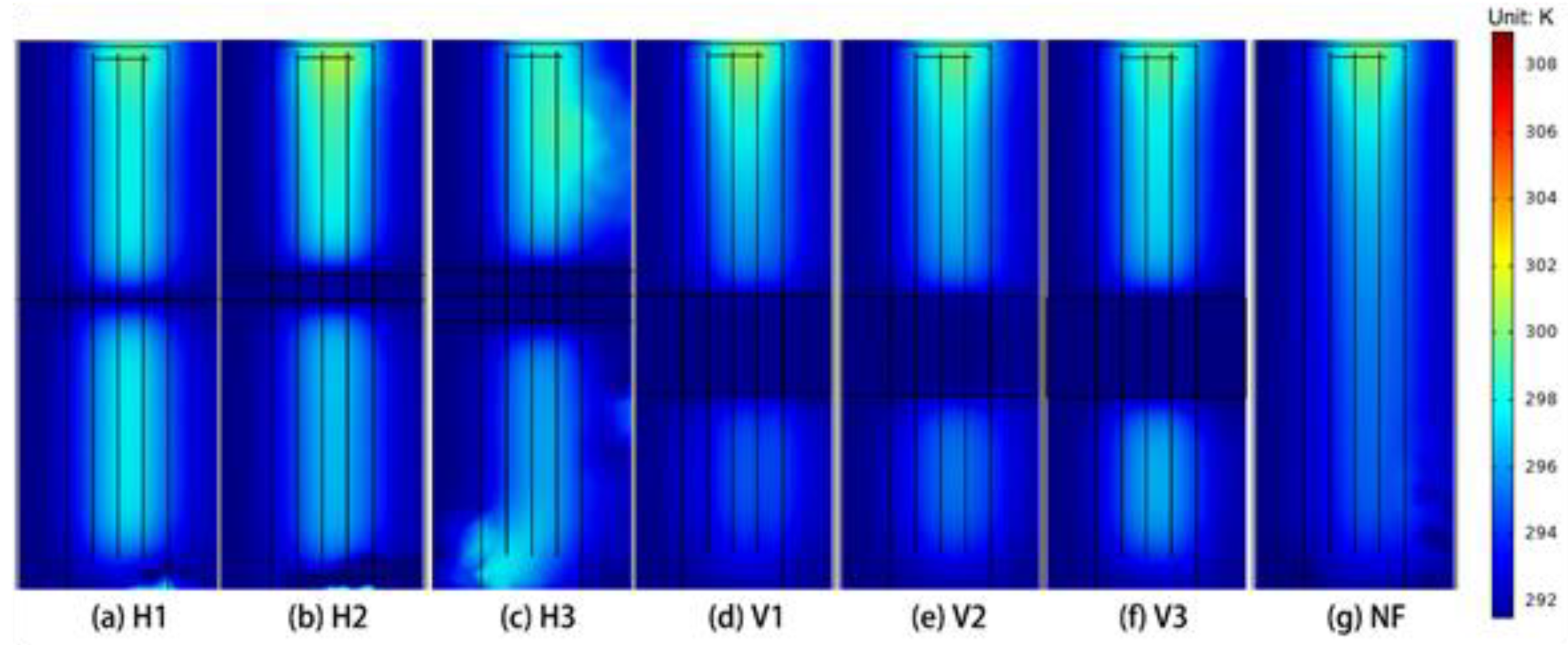
The consequences of temperature distributions are illustrated in Figure 8, Figure 9, Figure 10 and Figure 11. Figure 8, Figure 9 and Figure 10 show the temperature fields of different cases in the 15th month, which was in the middle of the second cooling period.
Figure 11 shows the temperature fields of different cases in the 23rd month, which was near the end of the second shutdown period.
According to the temperature contours, all cases show a remarkable lower temperature level near the fractures owing to the fracture water flow high-speed migrating when it was over the working condition and the shutdown period. Specifically:
In the horizontal fracture cases, as shown in Figure 8a–c, the lower temperature areas only concentrated on the depth where fractures located, but had rapid diminishing impacts on other depths. This means the impact of water flow on the thermal properties of the rock is confined in a small region around individual fractures.
Figure 9b shows the temperature contours in the middle of the interval between two fractures (2.5 m from each fracture) in Case H2. It demonstrated that the fracture water flow had a cooling influence on the interval between the two fractures. To compare, Figure 8a shows the temperature contour also 2.5 m away from the fracture in Case H1. However, since there was only one fracture, the cooling effect was not so obvious at the same depth as that of H2. This also supports that the inference above that the impacted region of water flow in an individual fracture is limited.
In terms of the vertical fracture cases, the low-temperature field was concentrated in the region where the fractures were located, according to the YOZ plane contours in Figure 8. As shown in Figure 10, at the XOY plane, because the vertical fractures were close to the U-pipes, water flow in them had an effect on a limited region around the U-pipes rows, not the entire region.
Similarly, during the shutdown period (Figure 11), the temperatures in all cases were in the similar range. This was also consistent with the mean temperatures in the ESRB shown in Figure 12. The influenced region still appeared exclusively near the U-pipes where the fractures were located.

4.2.2. Performance of U-Pipes and Heat Pump

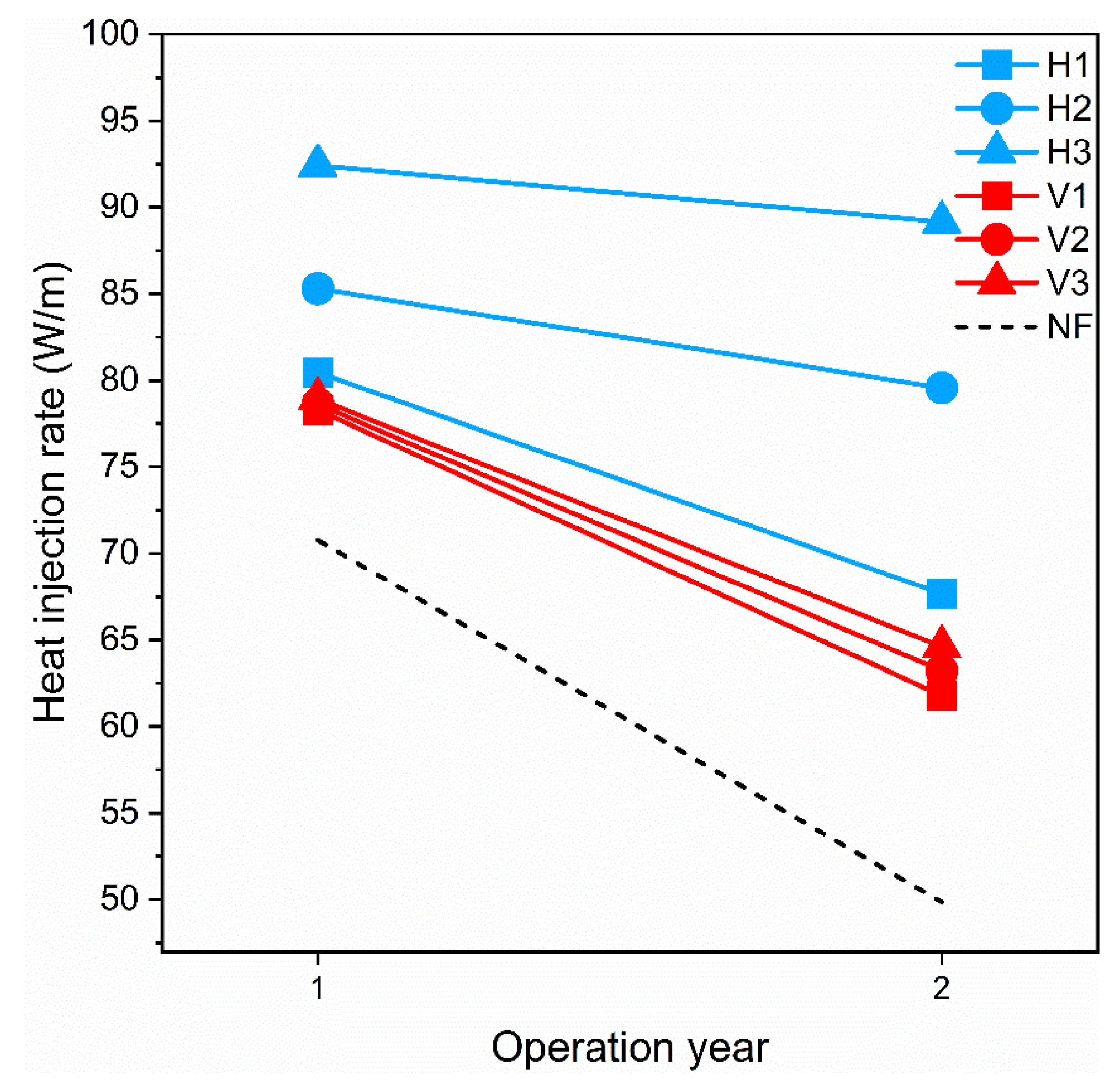
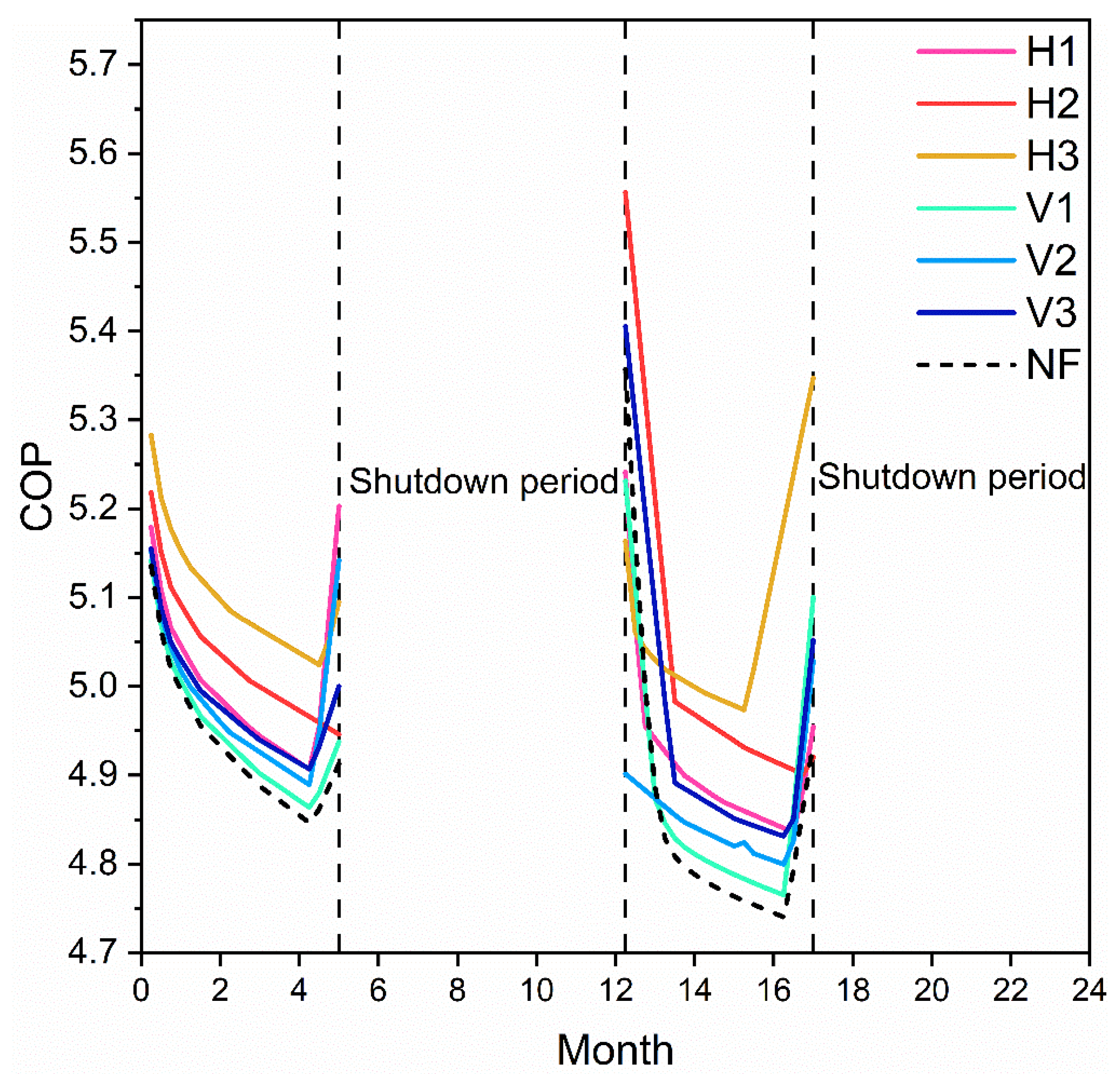
Indicators of U-pipes and the heat pump performance are shown in Figure 12, Figure 13, Figure 14 and Figure 15. Figure 12 shows the mean temperature of ESRB, Figure 13 shows the outlet temperature of GHEs, Figure 14 is the heat injection rate per unit length of the No. 5 U-pipe at the 15th month, and Figure 15 illustrates the COP of a specific heat pump. Specifically:
As depicted in Figure 12, the recovery of ESRB benefited greatly from the fracture water flow. In all cases, the mean temperature of ESRB at the end of the second shutdown period was higher than that of the first shutdown period, indicating there was a risk of heat accumulation over long term operation. However, such a risk could be mitigated as there were more fractures. For example, after the operation of 2 years, the mean temperature of ESRB in Case H3 was 1.77 K lower than that in the Case NF.
It was also found that the mean temperatures of ESRB in horizontal fracture cases were lower than those in vertical fracture cases. According to [27], heat transfer in the formation most occurs in horizontal planes, as indicated in the modeling results, the water flow in horizontal fractures was more capable of mitigating heat accumulation than that in vertical fractures.
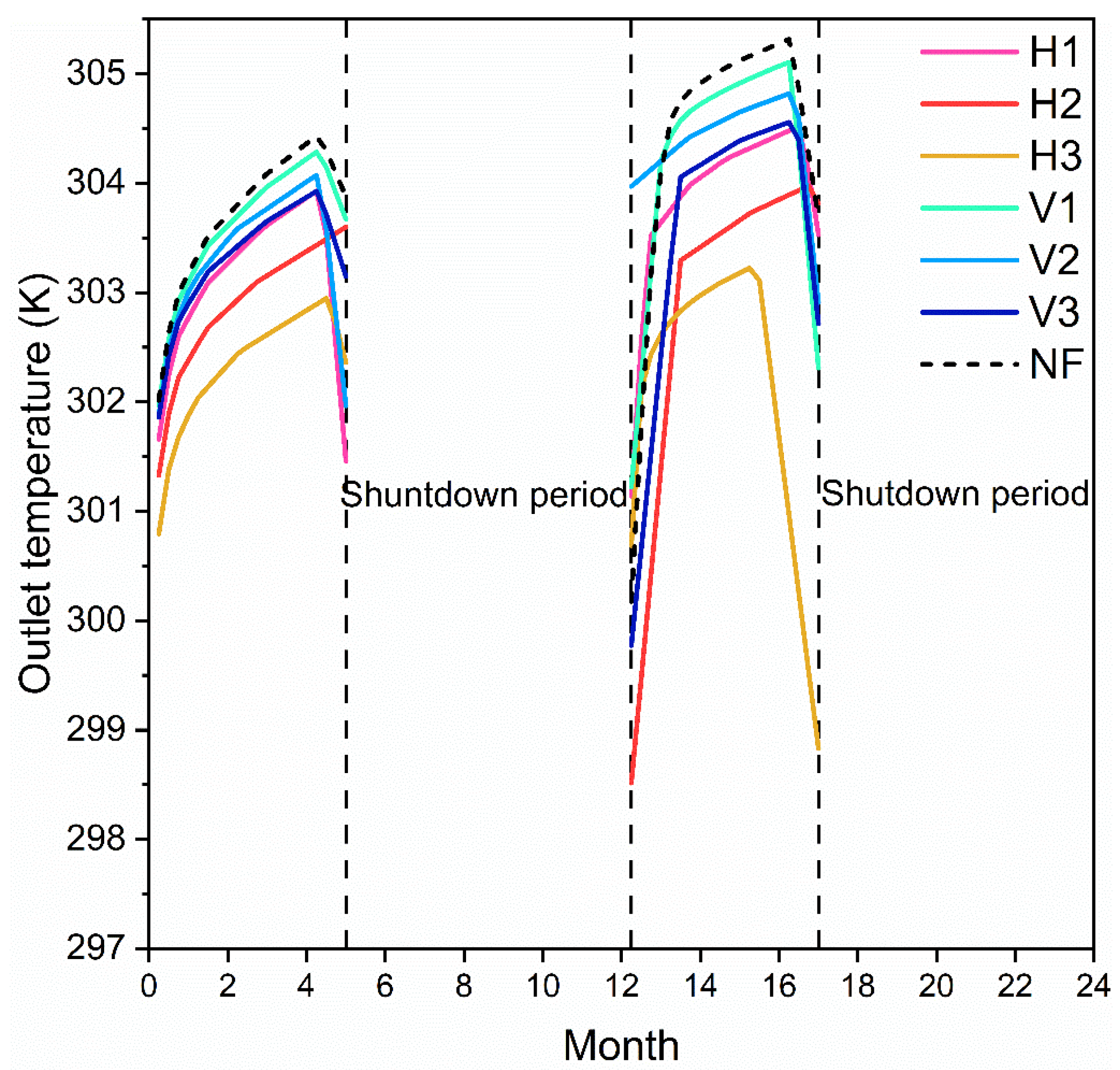
As the temperature of ESRB changed, the GHEs outlet temperature fluctuated. From Figure 12 and Figure 13, the outlet temperatures of GHEs in all cases increased from cooling Period 1 to Period 2, due to the rise of mean temperature in ESRB. It can also be seen that in each operation period, the cases with high outlet temperature, in turn, were NF, V1, V2, V3, H1, H2, and H3. In addition, the curve gradient in the second period of the two indicators was smaller than that in the first period, because the initial temperature at the second operating period of the ESRB had increased, leading to a lower heat exchange efficiency.
As the number of fractures increased in Figure 13, the outlet temperature decreased. It is worth noting that each horizontal fracture case showed a lower outlet temperature than their vertical case counterparts. The reason was mentioned in the last section—water flow in the horizontal fracture was more capable than vertical fractures in enhancing heat transfer among GHEs, ESRB, and surrounding formations. It can also be seen from Figure 14 that the heat transfer efficiency of U-pipes decreased from Cooling Period 1 to Period 2, indicating the heat transfer performance suffered from the irreversible change (heat accumulation) even though there were fracture water flow in the shutdown period. It is clear that the heat transfer efficiency from high to low is H3, H2, H1, V3, V2, V1, and NF. Specifically, during the second period, the figure for Case H3 was 78.83% higher than Case NF, and the most unfavorable case V1 was still 23.93% higher than Case NF.
Furthermore, the drop in heat transfer efficiency of the U-pipe in horizontal fracture cases was slighter than that of vertical fracture cases, and the drop of heat transfer efficiency in the NF case was greater than all other cases. This indicates that the decrease in heat transfer efficiency of the U-pipe was obviously suppressed by the fracture flow. It is also noticed that the heat injection rates of vertical cases were so close to each other, as stated above, the thermal impact of the fracture water flow was constrained within the near vicinity of the fractures.
The relationship between fractures and COP was in the inverse proportion (Figure 15 and Equation (6)). It is found that:
The more fractures, the higher COP, and the horizontal fracture cases all showed a higher COP than their vertical counterparts. Specifically, Case H3 showed 4.5% higher COP than Case NF, 2.30% higher than Case H1 and 2.61% higher than Case V3.
In the Cooling Period 2, the gap of COP values between fracture cases and NF cases became larger than in Period 1. This is because the fracture cases had a better ability to mitigate heat accumulation, hence improving COP. In general, because of the stronger ability of horizontal fractures to enhance heat transfer, its benefit to heat pump performance was more obvious.

5. Conclusions

In this study, a numerical simulation was performed to investigate the performance of GHEs and GSHPs, as well as heat accumulation risk in the formation, under the influence of fracture water flow. Examined factors included water velocities, different fracture numbers, and distributions of fractures. It was concluded that:
  • The fluid velocity in the fracture had a limited effect on the temperature distribution and heat pump performance.
  • Fracture water flow affected the temperature distribution in the vicinity of the fracture planes rather than a larger region and had a positive influence on GHE and heat pump performance.
  • In general, compared with vertical fractures, horizontal fracture water flow exerted a better influence on the performance of GHEs and GSHPs, and constraining the development of heat imbalance.
  • It is suggested that to take advantage of the influences of fracture water flow in designing and operating GSHP projects in regions with fractured rock formations and groundwater to improve system performance.
The benefits of groundwater flow in fractures to the performance of GCHP have been observed in real projects. The authors communicated with the operation contractor of a GCHP project in Tongren, Guizhou, China, where the heat exchanger pipes are buried in rock bodies contained developed horizontal fractures with abundant water flow. This office building project has a ratio of heat extracted from formation over released to formation equal to 0.5 and has been in operation for four years. Due to the heat transfer enhanced by water flows, the monitored ground temperature in ESRB has kept relatively constant. However, contributions of different influencing factors and detailed mechanisms remain unclear to the operator. The model in this study identified the factors and the extent of their impacts. In further work, this model can be refined to include the actual hydrogeologic conditions of a specific project, and support the designers and operator more accurately evaluation the heat imbalance and key techno-economic parameters of the GSHP system.

Author Contributions

Conceptualization, P.P. and W.Z.; methodology, W.Z.; software, D.H.; validation, D.H., W.Z. and P.P.; formal analysis, W.Z.; investigation, W.Z.; resources, P.P.; data curation, C.W. and P.P.; writing—original draft preparation, W.Z.; writing—review and editing, P.P. and C.W.; visualization, W.Z.; supervision, P.P.; project administration, P.P.; funding acquisition, P.P. All authors have read and agreed to the published version of the manuscript.

Funding

This was fund by the following project funds: National Natural Science Foundation of China, Grant/Award Number: 51864008; Natural Science Foundation of Guizhou Province: Grant/Award Number: [2018] 1039; Joint Funds of Department of Science and Technology of Guizhou Province and Guizhou University, Grant/Award Number: LH [2017] 7282; Youth Science and Technology Talents Growth Project of Guizhou, Grant/Award Number: KY [2017] 117; and National Natural Science Foundation of China, Grant/Award Number: 51904081.

Acknowledgments

In this section you can acknowledge any support given, which is not covered by the author contribution or funding sections. This may include administrative and technical support, or donations in kind (e.g., materials used for experiments).

Conflicts of Interest

The authors declare no conflict of interest.

References

  1. Dong, L.; Liang, H.; Zhang, L.; Liu, Z.; Gao, Z.; Hu, M. Highlighting regional eco-industrial development: Life cycle benefits of an urban industrial symbiosis and implications in China. Ecol. Modell. 2017, 361, 164–176. [Google Scholar] [CrossRef]
  2. Dong, S.; Wang, Y. The interaction of highly nonlinear solitary waves and viscoelastic half-space. In Proceedings of the 2017 Symposium on Piezoelectricity, Acoustic Waves, and Device Applications (SPAWDA), Chengdu, China, 27–30 October 2017; pp. 355–358. [Google Scholar]
  3. Lu, Y.; Cui, P.; Li, D. Which activities contribute most to building energy consumption in China? A hybrid LMDI decomposition analysis from year 2007 to 2015. Energy Build. 2018, 165, 259–269. [Google Scholar]
  4. Price, L.; Khanna, N.; Fridley, D.; Hasanbeigi, A.; Lu, H.; Wei, F.; Creyts, J.; Chrisman, K.; Agenbroad, J.; Ke, Y.; et al. Reinventing fire: China—The role of energy efficiency in China’s roadmap to 2050. Eur. Counc. Energy Effic. Econ. Summer Study 2017 2017, 113–120. [Google Scholar]
  5. Hou, J.; Cao, M.; Liu, P. Development and utilization of geothermal energy in China: Current practices and future strategies. Renew. Energy 2018, 125, 401–412. [Google Scholar] [CrossRef]
  6. Zeng, Z.; Zhang, X.; Asce, A.M.; Zhao, Y.; Lu, H. Performance of a ground source heat pump system and the heat-moisture migration of surrounding soils in karst areas. J. Perform. Constr. Facil. 2017, 31, 04017050. [Google Scholar] [CrossRef]
  7. Meng, B.; Vienken, T.; Kolditz, O.; Shao, H. Evaluating the thermal impacts and sustainability of intensive shallow geothermal utilization on a neighborhood scale: Lessons learned from a case study. Energy Convers. Manag. 2019, 199, 111913. [Google Scholar] [CrossRef]
  8. Hua, J.; Li, G.; Zhao, X.; Wu, W.; Li, D.; Li, Q. The hot stack performance of the shallow geothermal heat pump system with/without intensification state of groundwater seepage in Nanjing (China). Energy Build. 2017, 150, 558–566. [Google Scholar] [CrossRef]
  9. Hecht-Méndez, J.; De Paly, M.; Beck, M.; Bayer, P. Optimization of energy extraction for vertical closed-loop geothermal systems considering groundwater flow. Energy Convers. Manag. 2013, 66, 1–10. [Google Scholar] [CrossRef]
  10. You, T.; Li, X.; Cao, S.; Yang, H. Soil thermal imbalance of ground source heat pump systems with spiral-coil energy pile groups under seepage conditions and various influential factors. Energy Convers. Manag. 2018, 178, 123–136. [Google Scholar] [CrossRef]
  11. Li, B.; Han, Z.; Meng, X.; Zhang, H. Study on the influence of the design method of the ground source heat pump system with considering groundwater seepage. Appl. Therm. Eng. 2019, 160, 114016. [Google Scholar] [CrossRef]
  12. Tang, F.; Nowamooz, H. Factors influencing the performance of shallow Borehole Heat Exchanger. Energy Convers. Manag. 2019, 181, 571–583. [Google Scholar] [CrossRef]
  13. Hein, P.; Kolditz, O.; Görke, U.; Bucher, A.; Shao, H. A numerical study on the sustainability and efficiency of borehole heat exchanger coupled ground source heat pump systems. Appl. Therm. Eng. 2016, 100, 421–433. [Google Scholar] [CrossRef]
  14. Lei, X.; Zheng, X.; Duan, C.; Ye, J.; Liu, K. Three-dimensional numerical simulation of geothermal field of buried pipe group coupled with heat and permeable groundwater. Energies 2019, 12, 3698. [Google Scholar] [CrossRef] [Green Version]
  15. Zhang, W.; Yang, H.; Fang, L.; Cui, P.; Fang, Z. Study on heat transfer of pile foundation ground heat exchanger with three-dimensional groundwater seepage. Int. J. Heat Mass Transf. 2017, 105, 58–66. [Google Scholar] [CrossRef]
  16. Zhang, W.; Zhang, L.; Cui, P.; Gao, Y.; Liu, J.; Yu, M. The influence of groundwater seepage on the performance of ground source heat pump system with energy pile. Appl. Therm. Eng. 2019, 162, 114217. [Google Scholar] [CrossRef]
  17. Zhang, L.; Qin, X.; Tang, J.; Liu, W.; Yang, H. Review of arsenic geochemical characteristics and its significance on arsenic pollution studies in karst groundwater, Southwest China. Appl. Geochem. 2017, 77, 80–88. [Google Scholar] [CrossRef]
  18. Liu, X.; Lu, S.; Hughes, P.; Cai, Z. A comparative study of the status of GSHP applications in the United States and China. Renew. Sustain. Energy Rev. 2015, 48, 558–570. [Google Scholar] [CrossRef]
  19. Zeng, Z.; Zhao, Y.; Lu, H.; Wei, C. Experimental performance study of ground-coupled heat pump system for cooling and heating provision in karst region. Energy Build. 2018, 158, 971–986. [Google Scholar] [CrossRef]
  20. Kavanaugh, S.; Rafferty, K. Geothermal Heating and Cooling: Design of Ground-Source Heat Pump Systems; ASHRAE: Atlanta, GA, USA, 2014; ISBN 9781936504855. [Google Scholar]
  21. Casasso, A.; Sethi, R. Efficiency of closed loop geothermal heat pumps: A sensitivity analysis. Renew. Energy 2014, 62, 737–746. [Google Scholar] [CrossRef] [Green Version]
  22. Shao, H.; Hein, P.; Sachse, A.; Kolditz, O. Geoenergy Modeling II Shallow Geothermal Systems; Springer: Berlin, German, 2016; ISBN 9783319450551. [Google Scholar]
  23. Kahraman, A.; Çelebi, A. Investigation of the performance of a heat pump using waste water as a heat source. Energies 2009, 2, 697–713. [Google Scholar] [CrossRef]
  24. Ford, D.; Williams, P. Karst Hydrogeology and Geomorphology; John Wiley & Sons Ltd.: Hoboken, NJ, USA, 2013; ISBN 9781118684986. [Google Scholar]
  25. Worthington, S. A comprehensive strategy for understanding flow in carbonate aquifer. Speleogenes. Evol. Karst Aquifers 2003, 5. Available online: https://www.google.com.hk/url?sa=t&rct=j&q=&esrc=s&source=web&cd=3&ved=2ahUKEwiYw_jsgcnoAhVCFqYKHXvnAiYQFjACegQIARAB&url=http%3A%2F%2Fwww.speleogenesis.info%2Fdirectory%2Fkarstbase%2Fpdf%2Fseka_pdf4493.pdf&usg=AOvVaw3TJ8IQJN4q7hMbpxrMUUGj (accessed on 2 April 2020).
  26. Jiang, W.; Zhou, H.; Li, Y.; Liu, W.; Gong, C.; Guo, X. Permeability Measurement of Karst Fractured Media Based on Groundwater Velocity and Direction Within a Borehole. Saf. Environ. Eng. 2018, 25, 1-7+18. [Google Scholar]
  27. Zhu, Z. Numerical Simulation Study on the Typical Vertical Ground Source Heat Exchanger of GSHP; Zhejiang University: Hnagzhou, China, 2013. [Google Scholar]
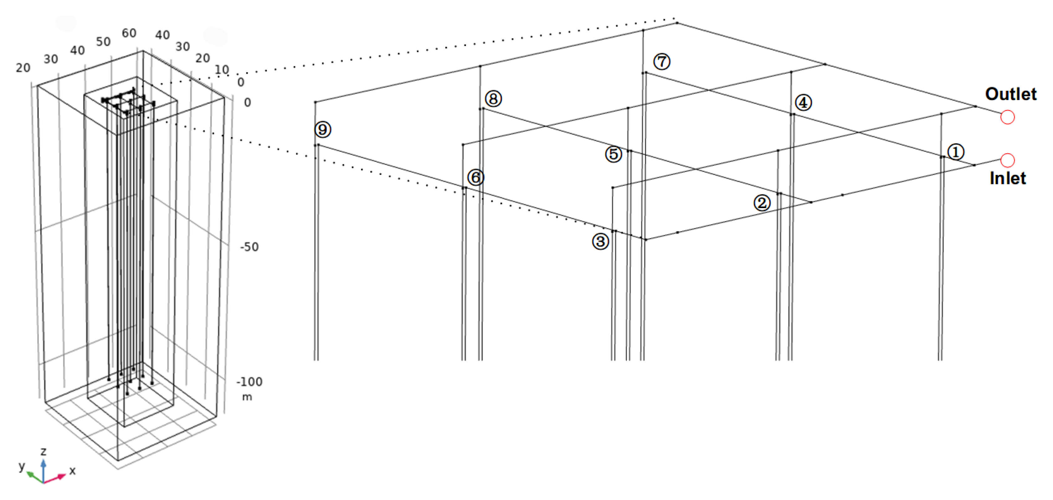
Figure 1. Geometrical model.
Energies 13 01647 g001
Figure 2. Horizontal fractures distribution: (a) cross-sections at the YOZ plane and (b) a cross-section at the XOY plane.
Energies 13 01647 g002
Figure 3. Vertical fractures distribution of V3: (a) a cross-section at the YOZ plane and (b) a cross-section at the XOY plane.
Energies 13 01647 g003
Figure 4. The geometric model of the ground heat exchanger (GHE).
Energies 13 01647 g004
Figure 5. Comparison between the recorded and simulated outlet temperatures.
Energies 13 01647 g005
Figure 6. Temperature contours (K) at the YOZ plane (X = 40 m) of fluid flow in fracture with different velocities in the 24th month.
Energies 13 01647 g006
Figure 7. Four indicators reflecting the heat pump performance and bedrock temperature under different velocities: (a) is the outlet temperature of GHEs, (b) is the coefficient of performance (COP) of the heat pump corresponding with outlet temperature, (c) is the heat injection rate per unit length of NO. 5 U-pipe at the 24th month, and (d) is the mean temperature of the “energy storage rock body” (ESRB).
Energies 13 01647 g007
Figure 8. The temperature distributions (K) of different cases at the YOZ plane (X = 40 m) in the 15th month (the middle of second cooling period).
Energies 13 01647 g008
Figure 9. The temperature distributions (K) of Case H1 and H2 at the depth of −47.5 m in the 15th month.
Energies 13 01647 g009
Figure 10. The temperature (K) distribution of Vertical fracture cases (Z = −60 m) in the 15th month.
Energies 13 01647 g010
Figure 11. The temperature (K) distribution at the YOZ plane (X = 40 m) in the 23rd month, near the end of the second shutdown period.
Energies 13 01647 g011
Figure 12. Mean temperature (K) of ESRB.
Energies 13 01647 g012
Figure 13. Outlet temperature (K) of GHEs.
Energies 13 01647 g013
Figure 14. Heat injection rate per length (W/m) of NO. 5 U-pipe.
Energies 13 01647 g014
Figure 15. COP of the heat pumps corresponding with outlet temperature.
Energies 13 01647 g015
Table 1. Thermal response test and formation thermal property parameters.
NameValueUnit
The depth of the hole102m
The depth of heat exchangers11m
The outer diameter of buried tube32mm
The inner diameter of buried tube26mm
U-tube spacing100mm
Thermal conductivity2.85W/m·K
Formation specific heat capacity800J/(kg·K)
U-tube thermal conductivity0.34W/m·K
The thermal conductivity of backfill material2.2W/m·K
The specific heat capacity of backfill material840J/(kg·K)
Table 2. Parameters used in simulations.
ParameterValue/RangeUnit
Permeability of Limestone10−15 [24]m2
Fracture conductivity10−5 [25]m/s
Thermal conductivity3W/m·K
Matrix heat capacity800J/(kg·K)
Carrying fluid velocity0.7m/s
Inlet temperature308K
Fluid flow velocity in fracture0.05, 0.5, 5mm/s
Initial temperature291.15K
U-Pipe inner diameter30mm