Abstract
Facing the future, whether working alone or with electric motors, a new type of variable compression ratio (VCR) engine that can achieve a high thermal efficiency under heavy load conditions is necessary. Hence, we propose a dual shaft control variable compression ratio (DSC-VCR) engine based on a gear-driven eccentric sleeve. With the improved position of gears, DSC-VCR allows for double larger gears to share the load, and the engine can operate with a larger eccentric size and a narrower adjustment range compared to other similar mechanisms. This helps to reduce the difficulty of chamber shape design, avoid collisions between valves and piston, and above all, makes the engine operate with a larger overexpansion ratio (OER, the ratio of expansion stroke and compression stroke) under all conditions to improve engine efficiency. Based on a 1.5 T four-cylinder engine, the OER can be increased to over 1.16 with the eccentric size of 6.5 mm. According to the theoretical thermal efficiency calculation while considering turbocharging, the per millimeter increase of eccentric size improves the theoretical efficiency by 0.0025–0.006. The predictive simulation presented that the reduction of residual gas helps to increase the compression ratio (CR) from 9.5 to 10.1 under a full load condition. Larger OERs and CRs help to reduce brake specific fuel consumption (BSFC) by 6%–8%. In the case of a 75% load, about 3.51% of efficiency increase was realized. All of these prove that DSC-VCR is a high-efficiency potential mechanism for the future.
1. Introduction
Currently, automotive engines are simultaneously developing towards a high self-efficiency and a high electrification. With the development of energy-saving technologies (Miller cycle, high tumble system, lean combustion, and fuel upgrading), engine thermal efficiency itself is improving. Variable compression ratio (VCR) engines show advantages when combined with the technologies shown above. The mass-produced variable compression turbocharging (VC-T) engine of Nissan realizes nearly 40% of brake efficiency with the combination of VCR, the Miller cycle, and a tumble valve [1]. In spark-assisted homogeneous charge compression ignition (HCCI), which is the combustion system of a Volkswagen, the compression ratio (CR) plays an important role [2]. Engines achieve an efficiency of 45% for both Toyota [3] and Honda [4] cars that operate with the Miller/Atkinson cycle and a high exhaust gas recirculation (EGR) rate. The key to expand the lean burn limit includes a high CR, a high tumble, and an improved ignition system. For many alternative fuel engines, such as bio-diesel [5,6,7] and methanol [8] engines, a VCR is also an essential way to improve thermal efficiency and ensure normal operation under heavy load or cold start conditions. For future automotive engines, it is necessary to integrate the technologies above to comprehensively improve engine performance. To sum up, the VCR engine does have a great potential for further development.
On the other hand, the involvement of electric motors makes up for the shortcomings of the part-load efficiency of traditional internal combustion engines. However, problems of electric cars like high cost, poor endurance, and slow charging speeds have not yet been properly solved [9]. Therefore, a combination of traditional engines and electric motors might become the mainstream in the transition period. In hybrid electric vehicles (HEVs) such as those made by Toyota and Honda [10,11,12], traditional engines usually work under heavy load conditions. As a result, one of keys to prolong the traditional engine industry is to improve the heavy-load efficiency when combined with electric motors.
Many researchers have focused on VCR development. Charles Mendler adjusted the CR by mounting the crankshaft in an eccentric “crankshaft cradle” that pivoted 10 degrees to raise and lower the crankshaft [13]. J. A. C. Kentfield realized the VCR and variable stroke through a multi-link mechanism [14]. Dennis N. Assanis et al. used the pressure reactive piston to adjust the CR [15]. Alberto Boretti and Joseph Scalzo presented a new design of a variable compression ratio engine with a multi-link mechanism [16]. For Honda, a dual-piston system can adjust the CR with a hydraulic system and a spring [17]. A new approach of a self-controlling variable compression ratio connecting rod was used by Frank Stefan Will and Dylan Mayson [18]. Kleeberg, H. (FEV) realizes the VCR by inserting an eccentric sleeve at the position of piston pin to change the position of piston [19]. Duchemin, M. and Collee, V. (MCE-5) realize the VCR with a large gear with mechanical loss reduction [20]. For the Nissan VCR engine mentioned above, a triangle component is used to change the piston movement and the CR [1]. However, traditional VCR engines have only shown obvious energy-saving effects for new European driving cycles (NEDCs) or worldwide-harmonized light vehicle test cycles (WLTCs), in which part load conditions account for the majority. However, this is inconsistent with real drive emission (RDE) that contain a wider range of operating conditions.
It is noteworthy that one kind of VCR mechanism rotates the eccentric sleeve inside the connecting rod big end through a gear system. This has the effect of overexpansion, with the expansion stroke larger than the compression stroke, which has the potential to improve the thermal efficiency under heavy load conditions. Leithinger S. F. realized the control of an eccentric sleeve through a set of internal gear transmission systems [21]. However, the processing of an internal gear is complex, and its cost is high. The rotation directions of eccentric sleeves and crank pins are opposite, which causes great friction loss. Gomecsys added a pair of intermediate gears in their gear system and named the new mechanism the Goengine [22]. After decreasing the gear load by optimizing the eccentric phase, Gomecsys reduced fuel consumption by 8% in WLTCs at a low cost with a 2–4 mm eccentric size and a maximum overexpansion ratio (OER, the ratio of the expansion stroke to the compression stroke) of 1.09 [23,24]. However, the way of putting the control shaft in the center of crankshaft limits the size of transmission gears. For some engines with high-overlap cranks, there may be no space for gears at all. Therefore, the eccentric size cannot be increased because of the low gear strength. The overexpansion ratio is at a low level, so the thermal efficiency under a heavy load cannot be obviously improved.
In order to increase the OER and further improve the thermal efficiency of an engine under heavy load conditions, we propose the concept of the dual shaft control (DSC)-VCR [25], which places the transmission gears on both sides of the crank pin. Thus, double larger gears with a higher strength can be applied to the DSC-VCR. After slightly changing the crank structure, the eccentric size of the DSC-VCR can be increased to 6.5 mm based on a 1.5 T spark ignition (SI) engine. Compared to other VCR mechanisms, the DSC-VCR has many advantages, as shown below.
- A larger eccentric size increases the max of the OER to 1.17, which increases engine efficiency.
- A larger eccentric size narrows the adjustment range of the eccentric sleeve for the same variation range of the CR and keeps the OER over 1.15 for all conditions.
- The narrower adjustment range of the eccentric sleeve reduces the difficulty of designing the chamber shape and avoids the collision between valves and piston.
- Simultaneously, a reduction of the residual gas fraction is helpful to increase the minimum CR from 9.5 to 10.1 under full load conditions, as Mazda [26] and Toyota [27] verified.
All advantages above are presented in this paper. A higher OER and CR help to improve engine efficiency under heavy load conditions, which are verified by theoretical thermal efficiency calculation and a predictive simulation based on the software of AVL-BOOST. The rest of this paper is divided into four parts. Section 2 shows the design of the DSC-VCR. Section 3 shows the theoretical thermal efficiency calculation of a turbocharged DSC-VCR engine. Section 4 presents a predictive simulation based on AVL-BOOST. Section 5 is the conclusion.
2. Design of DSC-VCR
As Figure 1 below shows, the main transmission gear (gear 1) is fixed on the eccentric sleeve for the DSC-VCR. Gear 2 and gear 3 are placed on both sides of the crank pin. Gear 2 drives gear 1, and gear 4 (coaxial with crankshaft) drives gear 3. The total transmission ratio i () is equal to 2. Gear 4 is driven by worm gearing and a motor. When the engine works without CR adjustment, gear 4 is fixed and the eccentric sleeve rotates at half the speed of crank because of the transmission ratio. When changing the CR, the motor drives worm gearing and gear 4. Therefore, gear 3, gear 2, gear 1, and the eccentric sleeve rotate, and the piston position is changed.
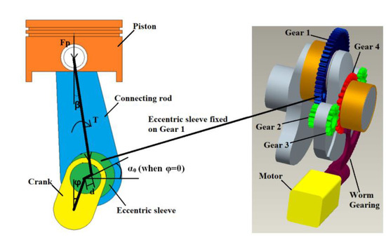
Figure 1.
Force analysis and gears position of the dual shaft control variable compression ratio (DSC-VCR).
The load of the transmission gear is same as that of the eccentric sleeve, which mainly depends on the eccentric size and the initial eccentric phase. The load of gear 1 can be calculated according to Equation (1).
In Equation (1), is the initial eccentric phase, which is the angle between the eccentric sleeve and the horizontal direction at compression top dead center (TDC) (φ = 0°). is the net force of piston, which is the summary of the gas force, and inertia force. is the angle between the connecting rod and the vertical direction. is the eccentric size.
A larger eccentric size is helpful to improve thermal efficiency. The load of the transmission gear is the key limit to the increase of eccentric size. In Section 1, three methods of engines realizing VCR with eccentric sleeve are mentioned. Figure 2 shows a comparison of gear positions for the DSC-VCR and other designs for engines with different crank overlap engines [24]. For the DSC-VCR, we improved the position of the gears (gears 2 and 3) to both sides of the crank, so two gears are allowed to share the gear load in this case. Meanwhile, there is enough space to increase the size of the gears. However, for other designs, only one gear can be placed in the middle of the crank shaft, and there is limited space for larger gears, especially for a crank with a high overlap. Therefore, a larger eccentric size of the DSC-VCR can be used to enhance the effect of overexpansion. The maximum eccentric size of the DSC-VCR can be increased to 6.5 mm after slightly changing the structure of crankshaft. With a larger eccentric size, the max of the OER can be increased linearly, as shown in Figure 3.
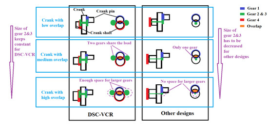
Figure 2.
Comparison of gear position for the DSC-VCR and other designs in different crank overlap engines [24].
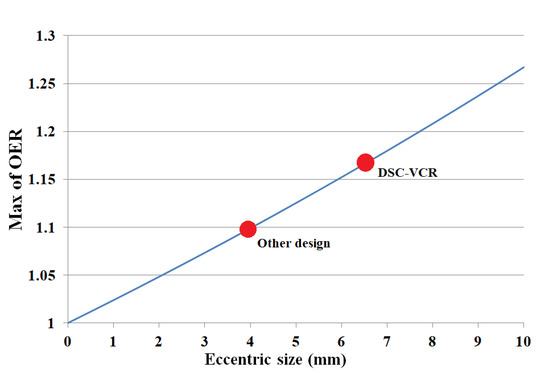
Figure 3.
Variation of the overexpansion ratio (OER) with different eccentric sizes.
Meanwhile, a larger eccentric size is helpful for reducing the adjustment range of the eccentric phase for the same CR range. For example, to change the CR from 10.1 to 17.9, the for other designs needs to vary from −45° to 45° in our conservative estimate [24]. However, for the DSC-VCR, only needs to vary from −17° to 18°. On the one hand, the reduced variation range helps the engine operate with a higher OER under all conditions, as shown in Figure 4; on the other hand, the reduced results in a reduced height difference between the compression TDC and the exhaust TDC under a full load condition. Hence, for the DSC-VCR, the clearance between the piston and the cylinder head at the compression TDC is much less, as shown in Figure 5, and more volume belongs to the chamber. Therefore, it is much easier to design the combustion chamber shape, and at the exhaust TDC, the clearance between the piston and the cylinder head for the DSC-VCR is larger, which is helpful for the avoidance of valve collision.
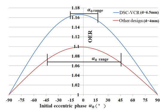
Figure 4.
Variation of the OER with initial eccentric phase
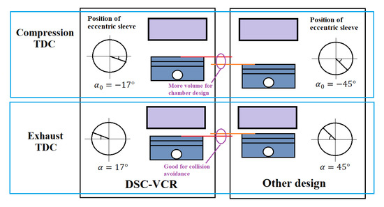
Figure 5.
Piston position at top dead center (TDC) under a full load condition for the DSC-VCR and the other design.
We described the gear design of the DSC-VCR in this section. With the improved position of gears, the DSC-VCR allows for double, larger size gears to share the load, and the engine can operate with a larger eccentric size and a narrower adjustment range. This helps to reduce the difficulty of chamber shape design, avoids the collision between the valves and the piston, and, above all, makes the engine operate with a larger OER under all conditions.
3. Theoretical Thermal Efficiency Calculation of DSC-VCR
One of main advantages of the DSC-VCR is the large OER brought by the large eccentric size, the influence of such on the thermal efficiency of can be preliminarily presented through the theoretical thermal efficiency. Theoretical thermal efficiency calculations usually do not take turbochargers into account, thus underestimating their results. The influence of turbochargers is taken into account in this paper, and the following assumptions are made.
- The internal thermal system of the engine, the inner circulation of the turbocharger, and the inter-cooler are regarded as a closed system.
- The combustion process is simplified to a constant volume process. A vibe combustion model based on AVL-BOOST is used as an auxiliary measure to get the related parameters during the whole calculation. The rate of heat release is adjusted to a quite large value, which approximates to a constant volume process.
- The compression and expansion strokes approximate to adiabatic processes. The heat transfer coefficient in the auxiliary model is set to 0.
- The mixture is considered as the ideal gas, and the physical property remains unchanged.
- Friction loss is not taken into account during the whole calculation.
The theoretical cycle of the DSC-VCR is shown in Figure 6 below. In Figure 6, the cycle a–b–c–d–e is the process in the cylinder that refers to adiabatic compression, constant volume heating, adiabatic expansion, and constant volume releasing in sequence. Q1 refers to the heat of the constant volume heating, and Q2 refers to the heat of the constant volume releasing. The cycle f–g–h–i is the process in the turbocharger that refers to constant pressure heating, adiabatic expansion, constant pressure releasing, and adiabatic compression in sequence. Q4 refers to the heat of the constant pressure heating, and Q5 refers to the heat of the constant pressure releasing. F–a is the process in the inter-cooler, and Q3 refers to the heat of the gas temperature decrease.
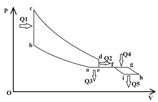
Figure 6.
Theoretical cycle of the DSC-VCR with turbocharging.
The theoretical efficiency can be calculated with Equation (2). In the equation, is the compression ratio of the engine. is the OER. is the pressure rise ratio, which is equal to . is the compression ratio of the compressor. is the volume ratio of the turbine. is the ratio of temperature decrease of the intercooler.
Take the 1.5 T four-cylinder engine as the base engine, with a bore of 77 mm, a stroke of 80.5 mm, and a compression ratio of 9.5. For the DSC-VCR, the cases of are considered. Take the case of as an example; the main parameters of the DSC-VCR are shown in Table 1. In order to keep the same intake stroke under the full load condition with a CR of 9.5, the crank radius needs to increase according to the different eccentric sizes. For each eccentric size, the CR varies from 9.5 to 17.5 by adjusting . Meanwhile, all the parameters of the DSC-VCR such as the stroke length, the expansion ratio, and the OER change, too. The variation of the OER with different and ER values for the CR = 13.5 is shown in Figure 7. In the case of a constant CR, ER, and OER of the engine increase linearly with the increase of d.

Table 1.
Parameters of the DSC-VCR with different (eccentric size) values.
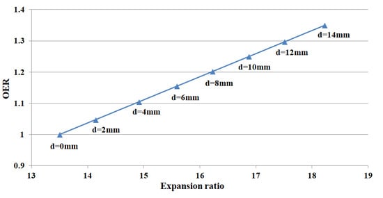
Figure 7.
Variation of the OER with different values and the ER for a CR = 13.5.
The main parameters of Equation (2) under different load conditions are shown in Table 2 below. For 50%, 30%, and 10% loads, , , and are 1, which means the turbocharger does not work. Other parameters are calculated according to the AVL-BOOST model.
Table 2.
The main parameters of Equation (2).
The theoretical thermal efficiency of the DSC-VCR with variations of the ER under different engine loads and CRs is shown in Figure 8. In the case of a constant CR for each curve, the theoretical efficiency of the engine is significantly improved with the increase of . For the CR of 9.5, the efficiency can be improved by 0.0035–0.006 per millimeter increase of . For a CR of 17.5, the efficiency can be improved by 0.0025–0.004 per millimeter increase of . For the 100% and 75% loads in the absence of knock, the efficiency is higher because of the turbocharger. For the conditions without boosting, the efficiency is only influenced by for different load conditions. Therefore, to further improve engine efficiency, increasing the engine load and the CR with knock avoidance and by using a larger to increase the ER is quite an effective measure.
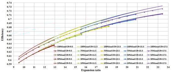
Figure 8.
Theoretical efficiency of the DSC-VCR with different engine loads, CRs, and ERs.
4. The Predictive Simulation
Research by Gomecsys confirmed the feasibility of the Goengine and its considerable effect in reducing fuel consumption with smaller eccentric sizes. Hence, we built a predictive model of the DSC-VCR based on AVL-BOOST to show further efficiency improvement due to the larger OER under heavy load conditions.
4.1. Model Description
4.1.1. Model of Base Engine
The main dimensions of the base engine are shown in Table 3.
Table 3.
Main dimensions of the base engine.
The combustion process is described by fractal model. For the heat transfer, the Hohenberg model is used [28]. We simulated three cases under high load conditions, including the maximum torque case with 1750 rpm (case 1), the maximum power case with 5500 rpm (case 2), and the high efficiency case with 2300 rpm and a 75% load (case 3). According to the experimental data, the torque and brake specific fuel consumption (BSFC) were validated as below in Figure 9. The highest octane number (ON) of the base engine in case 1 was 111.7. Thus, 112 was considered as the knock limit number.
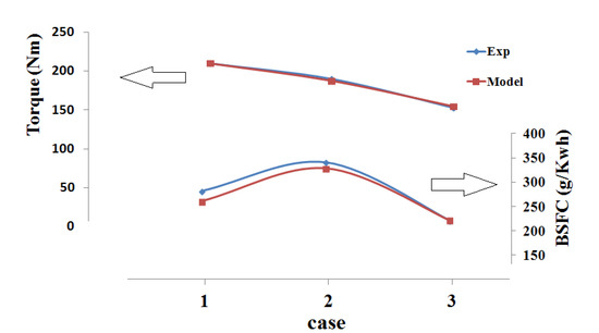
Figure 9.
Torque and brake specific fuel consumption (BSFC) validation of the base engine model.
4.1.2. Model of DSC-VCR
Based on the base engine model, we built the model of the DSC-VCR by only changing the piston movement and the CR while the keeping boundary conditions and other parameters not mentioned (such as the excess air ratio and boost pressure) unchanged. Two assumptions were made at first. (a): For the combustion model, the DSC-VCR keeps the same parameters as the base engine model. (b): The mechanical friction was calculated according to , where is the joint load, and is the friction coefficient validated by friction of the base engine that keeps constant in the same joint of the DSC-VCR.
The DSC-VCR model is established in three steps:
Step 1: The DSC-VCR has unconventional piston movement because of the eccentric sleeve. In AVL-BOOST, ‘User Defined Piston Motion’ is used to define the piston movement of the DSC-VCR. The CR of the DSC-VCR for each case should be increased until the calculated ON approaches 112. The variation of the ON and the CR in this step is shown below in Figure 10.
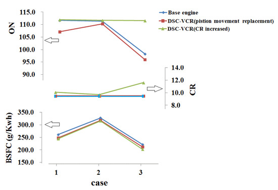
Figure 10.
Variation of the octane number (ON), the CR, and the BSFC for different engines in step 1.
Step 2: The rate of heat release for the DSC-VCR must be different due to the variation of residual gas fraction, the CR, and turbulence. Therefore, the ignition timing (IT) must be optimized. By monitoring the ON and not allowing it to exceed 112, we can avoid knock while adjusting the IT and the CR. The details of the optimization are shown in Figure 11. For cases 1 and 3, we chose the IT and the CR with the lowest BSFC. For case 2, with further consideration of nitrogen oxide (NOX) generation and exhaust temperature, the IT of −17 deg was chosen.
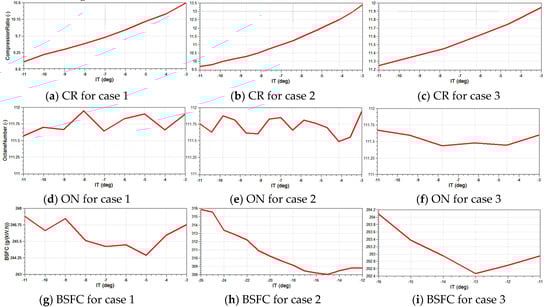
Figure 11.
The CR and ignition timing (IT) optimization in step 2.
Case 3 was one of the common working conditions of HEVs; therefore, we added another case (other design) with an eccentric size of 4 mm, which is the maximum size among all of the similar mechanisms we could find in reference [23]. To compare with the (DSC-VCR’s) similar mechanism, the advantage of the DSC-VCR could be presented more obviously.
During steps 1 and 2, the way to adjust the CR for the DSC-VCR is to change by rotating the eccentric sleeve. Meanwhile, the stroke length is different, which is shown in Figure 12 below. For the CR adjustment range from 10.1 to 17.9, needs to vary from −16° to 17°. In case 1, the engine was under the full load, and with the increased crank radius of 42.48 mm, the intake stroke of the DSC-VCR was the same as that of the base engine. For other cases, the engine load was lighter, so the intake stroke was shorter, which realized auto-downsizing.
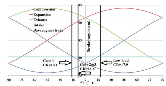
Figure 12.
Variation of stroke length with
Thus far, the piston movement for each case of the DSC-VCR was confirmed. They are shown in Figure 13 below.
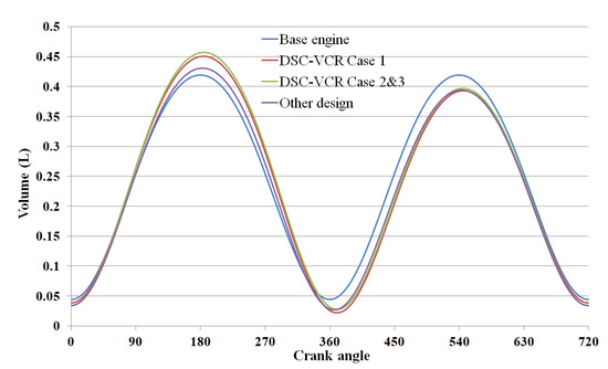
Figure 13.
Piston movement for the base engine, the DSC-VCR, and the other design [23].
Step 3: Another effect of overexpansion is the temperature decrease of the exhaust gas. Under high speed and high load conditions, to ensure the normal operation of turbines and catalysts, it is usually necessary to enrich the mixture to reduce the exhaust temperature. However, it is unnecessary for the DSC-VCR, as the overexpansion decreases the exhaust temperature. Therefore, the excess air ratio of the DSC-VCR could be increased from 0.831 to 0.850 in case 2. This helped to reduce the BSFC by about 2.21%.
4.2. Results and Discussions
4.2.1. Results
Figure 14 shows the results comparison of the torque and the BSFC between the base engine and the DSC-VCR for three cases. The DSC-VCR improved about 6.57%, 4.81%, and 6.19% of torque, and it saved about 6.19%, 8.07%, and 8.67% of the BSFC compared to the base engine for each case.
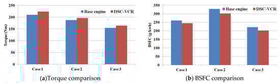
Figure 14.
Comparison of torque and the BSFC for the base engine and the DSC-VCR.
Figure 15 shows the comparison of the energy balance in case 3. The total energy for the DSC-VCR and the other design was less than that of the base engine, because the shorter intake stroke and higher average piston speed resulted in a decrease of the total mixture mass. However, about 3.51% and 2.61% improvements of the brake thermal efficiency of the DSC-VCR and the other design was realized because of larger the OER and the CR.
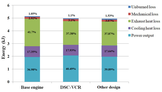
Figure 15.
Comparison of energy balance in case 3.
4.2.2. Improved Knock Resistance
In AVL-BOOST for gasoline engines, a knock model calculates the minimum octane number required for engine operation free of knock. The threshold for the onset of knock is exceeded if the integral is larger than one before the end of combustion is reached, in which is the ignition delay at the unburned zone’s condition. The ignition delay for the knock model depends on the octane number of the fuel and the gas condition, which can be calculated below:
In Equation (3), is the gas pressure, and is the temperature of unburned zone, which is the same as the mean temperature during the intake and compression stroke [28].
Therefore, ON can be calculated as below:
As shown in Figure 13, for the DSC-VCR, the volume at the exhaust TDC was smaller than that at the compression TDC, which means that the piston rose higher at the exhaust TDC to push residual gas out of the cylinder. In case 1, the percentage of residual gas of the base engine was 5.63%, but for the DSC-VCR without an increased CR (the red one in Figure 10), the residual gas percentage was 2.62%. Hence, the mean mixture temperature of the DSC-VCR was about 25 K lower than that of the base engine during the intake and compression stroke, as shown in Figure 16. Therefore, the calculated ON was lower than that of the base engine, and the CR could be increased through step 1.
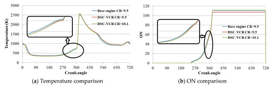
Figure 16.
Comparison of the in-cylinder temperature and ON for different engines in case 1.
4.2.3. Effect of Over Expansion
The overexpansion of the DSC-VCR can be regarded as another way to make use of the exhaust energy. Compared with turbocharging, which also recycles exhaust energy, the energy utilized by overexpansion is on a higher grade. Therefore, the entropy increase in the cycle is smaller, and the thermal efficiency is higher. Compared with the Miller cycle, of which expansion ratio also larger than the CR, overexpansion does not cause the problem of intake mass reduction. Furthermore, overexpansion can be combined with turbocharging and the Miller cycle to further improve engine efficiency. The pressure-volume (P–V) diagram in Figure 17 shows that, in case 3, the DSC-VCR gained more power output than the base engine with the same boost pressure. For the other design, the effect of overexpansion is less obvious. Another advantage of overexpansion is the temperature decrease of exhaust gas, which helps to avoid the enrichment of mixture, as presented in step 3 above.
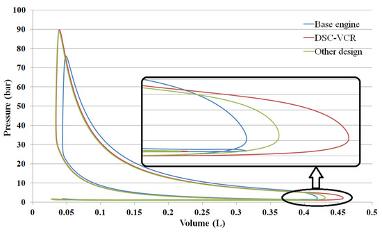
Figure 17.
Comparison of pressure-volume (P–V) diagram for different engines in case 3.
4.2.4. Mechanical Loss
For the DSC-VCR, the mechanical loss is focused on the friction of the bearings, and the friction between the piston and the liner. Figure 18 shows each component of friction power in case 3. The internal bearing of connecting rod big end was the main reason for the increase of mechanical loss for the DSC-VCR. Different from the base engine, the DSC-VCR had two half-speed big-end bearings. The outside bearing, between the eccentric sleeve and the big end, was 43.5% larger than that of the base engine. The load of the inner bearing (between the eccentric sleeve and the crank pin) was 85% higher than that of the base engine because of the increase of the inertia mass (two bearings, big end, and eccentric sleeve). The increase of bearing size and load led to the increase of friction loss. Furthermore, the friction of additional the needle bears for gear 2 and 3 could not be neglected under high-speed conditions. The reason for the friction increase of the DSC-VCR between the piston and the liner was the larger crank radius, which led to an average stroke length that was 5.65% larger than that of the base engine. We increased the length of the connecting rod to mitigate the influence; however, the friction loss was still increased by 3.85%.
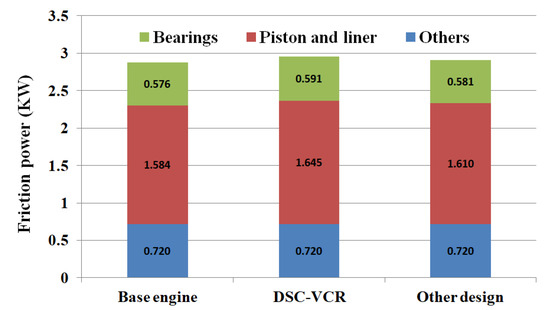
Figure 18.
Comparison of engine friction power in case 3.
Assumption (b) presented that the friction coefficient of the DSC-VCR is the same as that of the base engine in the same joint, which means that we only considered the influence of joint load on the friction. In fact, both joint load and speed have a great influence on . Sander D.E. showed an increase in the friction coefficient with a higher oil pressure or a higher speed [29]. Considering the increase of joint load and the decrease of speed for DSC-VCR bearings, the variation of friction coefficient is difficult to estimate without further studies. However, with the development of an engine lubrication system and bearings friction-reducing technology, the friction coefficient of the DSC-VCR is likely to be lower than that of the base engine.
4.2.5. Comparison of Simulation Results
As shown in Figure 8, the theoretical thermal efficiency of the DSC-VCR increased by 5.5% under the 75% load condition compared to the base engine. The theoretical efficiency calculation did not take into account the time loss of combustion, heat transfer loss, and mechanical friction loss. Therefore, the thermal efficiency increase was larger than our simulation results, which confirmed that our simulation did not overestimate the effect of the DSC-VCR.
According to the data given by Gomecsys, under the 75% and 100% load conditions, the fuel consumption of the Goengine can be reduced by 4.2% compared with the base engine, and the overexpansion effect (OER = 1.07 for CR = 8) accounts for about 3.5% [30]. In our simulation, DSC-VCR could reduce fuel consumption by 8.67% (case 3, 75% load) and 6.19% (case 1, full load). There are two main reasons for the difference. One is that Goengine pursues the power output. By increasing the boost ratio, the engine reaches the knock limit instead of pursuing higher thermal efficiency by increasing the CR like the DSC-VCR. As seen in the red one shown in Figure 10, the intermediate calculation cases of the DSC-VCR, which only replaced the piston motion rule and did not improve the CR, were similar to Goengine. The fuel consumption of the two intermediate cases could be reduced by 4.4% and 4.8%. The other reason is that for the DSC-VCR, the eccentric size (6.5 mm) was larger, and the OER was more than 1.15. The effect of the larger OER was verified according to the theoretical efficiency calculation.
For this section, a predictive model was used to show the main advantages of the DSC-VCR with a large eccentric size. It can reduce fuel consumption by 6%–8% at full load, and thermal efficiency can reach 40.49% at a 75% load. The final brake efficiency does not seem to be remarkable, because the research object was a port fuel injection (PFI)-turbocharged engine with the highest thermal efficiency of only 36.98%. In order to eliminate the interference of other unrelated factors, the simulation process adopted in this paper was carried out under the same conditions as the base engine as close as possible. That is to say, depending on the change of the DSC-VCR mechanism alone, the brake efficiency can be increased by 3.51%. Combined with other energy-saving technologies such as direct injection, high tumble flow, and stratified or homogeneous lean combustion, the brake efficiency of the DSC-VCR can be expected to achieve 45% or higher.
5. Conclusions
Compared with conventional VCR engines, the DSC-VCR shows a high efficiency potential under heavy load conditions because of overexpansion. We presented the design of the DSC-VCR, theoretical thermal efficiency calculation, and a predictive modeling study in this paper. The conclusions are shown below.
- With the improved position of gears, the DSC-VCR allows double, larger size gears to share the load, and the engine can operate with a larger eccentric size and a narrower adjustment range. This helps to reduce the difficulty of designing the chamber shape, avoids the collision between the valves and pistons, and, above all, makes the engine operate with a larger OER under all conditions. Based on the 1.5 T four-cylinder engine, the OER can be increased to over 1.16 with an eccentric size of 6.5 mm.
- According to the theoretical thermal efficiency calculation that considers turbocharging, the per millimeter increase of the eccentric size would improve the theoretical efficiency by 0.0025–0.006. To further improve engine efficiency, increasing the engine load and compression ratio by avoiding knock and using larger eccentric size to increase expansion ratio are the most effective measures.
- The predictive simulation presented the main characteristics of the DSC-VCR. Based on the 1.5 T four-cylinder engine, the reduction of residual gas helps to increase the CR from 9.5 to 10.1 under the full load condition. A larger OER and CR help to reduce the BSFC by 6%–8%. In case of a 75% load, an efficiency increase of about 3.51% was realized.
- The maximum brake efficiency of the DSC-VCR was 40.49% under the 75% load condition. The final efficiency did not seem to be remarkable, because the base engine was just a turbocharging PFI engine with an efficiency of 36.98%. However, the simulation result showed enormous potential for the efficiency improvement of the DSC-VCR under high load conditions. Furthermore, by combining it with other energy-saving technologies such as direct injection, high tumble flow, and stratified or homogeneous lean combustion, the brake efficiency of the DSC-VCR can be expected to achieve even 45% or higher.
Author Contributions
Writing—original draft preparation, S.Y.; others, J.L. All authors have read and agreed to the published version of the manuscript.
Funding
This research received no external funding.
Acknowledgments
The author would like to thank AVL/CN for assisting the piston movement definition of DSC-VCR model.
Conflicts of Interest
The authors declare no conflict of interest.
Acronyms
| VCR | variable compression ratio |
| DSC-VCR | double shaft controlled variable compression ratio |
| VC-T | variable compression turbocharging |
| OER | overexpansion ratio |
| CR | compression ratio |
| BSFC | brake specific fuel consumption |
| HCCI | homogeneous charge compression ignition |
| EGR | exhaust gas recirculation |
| HEV | hybrid electric vehicle |
| NEDC | new European driving cycle |
| WLTC | worldwide-harmonized light vehicles test cycle |
| RDE | real drive emission |
| TDC | top dead left |
| ER | expansion ratio |
| ON | octane number |
| IT | ignition timing |
| TKE | turbulent kinetic energy |
| PFI | Port fuel injection |
Symbols
| the gear load | |
| the summary force of the gas force and inertia force on the piston | |
| the angle between connecting rod and vertical direction | |
| eccentric size | |
| the angle between eccentric sleeve and horizontal direction at compression TDC | |
| . | transmission ratio |
| CR | |
| specific heat ratio | |
| pressure ratio | |
| OER | |
| the volume ratio of the turbine | |
| the compression ratio of the compressor | |
| ignition delay at the unburned zone’s condition | |
| the ratio of temperature decrease of intercooler | |
| the gas pressure | |
| he temperature of unburned zone | |
| Friction | |
| friction coefficient | |
| joint load |
References
- Kojima, S.; Kiga, S.; Moteki, K.; Takahashi, E.; Matsuoka, K. Development of a new 2L gasoline VC-Turbo engine with the world’s first variable compression ratio technology. SAE Tech. Pap. 2018, 1, 0371. [Google Scholar]
- Chiodi, M.; Kaechele, A.; Bargende, M.; Wichelhaus, D.; Poetsch, C. Development of an innovative combustion process: Spark- assisted compression ignition. SAE Int. J. Engines 2017, 10, 5. [Google Scholar] [CrossRef]
- Nakata, K.; Nogawa, S.; Takahashi, D.; Kumagai, A.; Suzuki, T. Engine technologies for achieving 45% thermal efficiency of S.I. engine. SAE Int. J. Engines 2016, 9, 1. [Google Scholar] [CrossRef]
- Ikeya, K.; Takazawa, M.; Yamada, T.; Park, S.; Tagishi, R. Thermal efficiency enhancement of a gasoline engine. SAE Int. J. Engines 2015, 8, 4. [Google Scholar] [CrossRef]
- Puhan, S.; Jegan, R.; Balasubbramanian, K.; Nagarajan, G. Effect of injection pressure on performance, emission and combustion characteristics of high linolenic linseed oil methyl ester in a DI diesel engine. Renew. Energy 2009, 34, 1227–1233. [Google Scholar] [CrossRef]
- Gumus, M. A comprehensive experimental investigation of combustion and heat release characteristics of a biodiesel (hazelnut kernel oil methyl ester) fueled direct injection compression ignition engine. FUEL 2010, 89, 2802–2814. [Google Scholar] [CrossRef]
- Debnath, B.K.; Saha, U.K.; Sahoo, N. Effect of compression ratio and injection timing on the performance characteristics of a diesel engine running on palm oil methyl ester. J. Power Energy 2013, 227, 368–382. [Google Scholar] [CrossRef]
- Costa, R.C.; Sodré, J.R. Compression ratio effects on an ethanol/gasoline fuelled engine performance. Appl. Therm. Eng. 2011, 31, 278–283. [Google Scholar] [CrossRef]
- Chan, C.C.; Bouscayrol, A.; Chen, K. Electric, hybrid, and fuel-cell vehicles: Architectures and modeling. IEEE Ind. Electron. 2010, 59, 589–598. [Google Scholar] [CrossRef]
- Overington, S.; Rajakaruna, S. High-efficiency control of internal combustion engines in blended charge depletion/charge sustenance strategies for plug-in hybrid electric vehicles. IEEE Ind. Electron. 2015, 64, 48–61. [Google Scholar] [CrossRef]
- Kawamoto, N.; Naiki, K.; Kawai, T.; Shikida, T.; Tomatsuri, M. Development of new 1.8-liter engine for hybrid vehicles. SAE Tech. Pap. 2009, 1, 1061. [Google Scholar]
- Kitayama, S.; Saikyo, M.; Nishio, Y.; Tsutsumi, K. Torque control strategy and optimization for fuel consumption and emission reduction in parallel hybrid electric vehicles. Struct. Multidisc. Optim. 2015, 52, 595. [Google Scholar] [CrossRef]
- Mendler, C.; Gravel, R. Variable Compression Ratio Engine. SAE Tech. Pap. 2002, 1, 1940. [Google Scholar]
- Kentfield, J.A.C. Extended, and Variable, Stroke Reciprocating Internal Combustion Engines. SAE Tech. Pap. 2002, 1, 1941. [Google Scholar]
- Dennis, N.; Assanis, W.C.; Choi, I.; Ickes, A.; Jung, D.; Martz, J.; Nelson, R.; Sanko, J.; Thompson, S.; Brevick, J.; et al. Pressure Reactive Piston Technology Investigation and Development forSpark Ignition Engines. SAE Tech. Pap. 2005, 1, 1648. [Google Scholar]
- Boretti, A.; Scalzo, J. Exploring the Advantages of Variable Compression Ratio in Internal Combustion Engines by Using Engine Performance Simulations. SAE Tech. Pap. 2011, 1, 364. [Google Scholar]
- Kadota, M.; Ishikawa, S.; Yamamoto, K.; Kato, M.; Kawajiri, S. Advanced control system of variable compression ratio (VCR) engine with dual piston mechanism. SAE Tech. Pap. 2009, 2, 1009–1018. [Google Scholar] [CrossRef]
- Will, F.S.; Mayson, D. Combustion Simulations for a Self Controlling Variable Compression Ratio Connecting Rod. SAE Tech. Pap. 2012, 1, 1154. [Google Scholar]
- Kleeberg, H.; Tomazic, D.; Dohmen, J.; Wittek, K.; Balazs, A. Increasing efficiency in gasoline powertrains with a two-stage variable compression ratio (VCR) system. SAE Tech. Pap. 2013, 1, 288. [Google Scholar]
- Duchemin, M.; Collee, V. Profile optimization of the teeth of the double rack-and-pinion gear mechanism in the MCE-5 VCRi engine. SAE Int. J. Engines 2016, 9, 1786–1794. [Google Scholar] [CrossRef][Green Version]
- Leithinger, S.F. Reciprocating Piston Type Internal Combustion Engine with Variable Compression Ratio. U.S. Patent 5,908,014, 1 June 1999. [Google Scholar]
- De Gooijer, B. VCR breakthrough. Engine Technol. Int. 2014, pp. 58–59. Available online: https://www.ukimediaevents.com/publication/e5b6bd2e/56 (accessed on 31 March 2020).
- De Gooijer, B. New GoEngine VCR development. Engine Technol. Int. 2010, 1, 42–44. [Google Scholar]
- Gomecsys Homepage. Available online: https://gomecsys.com/our-product/gomecsys-vcr-technology (accessed on 29 November 2019).
- Lin, J. Compression-ratio-adjustable engine capable of being suitable for any crankshaft overlapping degree without damaging crankshaft structure. Patent CN203879624U, 15 October 2014. [Google Scholar]
- Goto, T.; Isobe, R.; Yamakawa, M.; Nishida, M. The new Mazda gasoline engine skyactiv-G. Auto Technol. 2011, 11, 40–47. [Google Scholar]
- Yamada, T.; Adachi, S.; Nakata, K.; Kurauchi, T.; Takagi, I. Economy with superior thermal efficient combustion (ESTEC). SAE Tech. Pap. 2014, 1, 1192. [Google Scholar]
- AVL. BOOST Ver. 5.1 User Guide. Available online: 0H0H0Hhttp://www.avl.com (accessed on 31 March 2020).
- Sander, D.E.; Allmaier, H.; Priebsch, H.H.; Reich, F.M.; Witt, M.; Füllenbach, T.; Skiadas, A.; Schwarze, H. Impact of high pressure and shear thinning on journal bearing friction. Tribol. Int. 2015, 81, 29–37. [Google Scholar] [CrossRef]
- Gomecsys Homepage. Available online: http://www.gomecsys.com/#home/product (accessed on 30 June 2015).


© 2020 by the authors. Licensee MDPI, Basel, Switzerland. This article is an open access article distributed under the terms and conditions of the Creative Commons Attribution (CC BY) license (http://creativecommons.org/licenses/by/4.0/).