Fault Ride Through Capability Improvement of DFIG Based Wind Farm Using Nonlinear Controller Based Bridge-Type Flux Coupling Non-Superconducting Fault Current Limiter

 , , ,
, , ,
Abstract
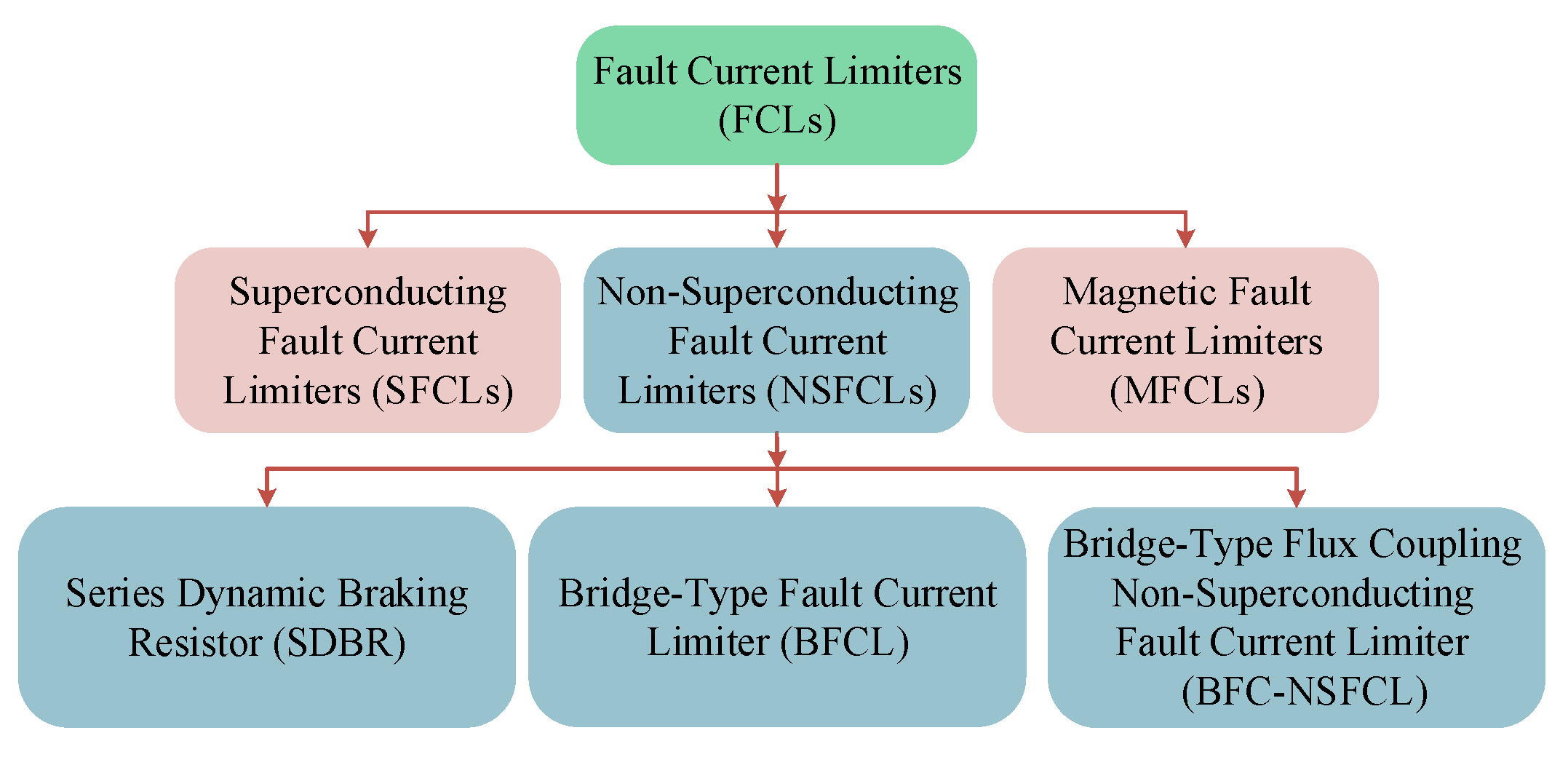
:1. Introduction
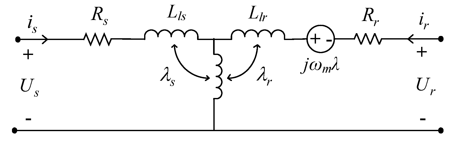
2. Modeling of DFIG
2.1. Wind Power Modeling
2.2. Modeling of DFIG Under Normal Condition
2.3. Modeling of DFIG Under Fault
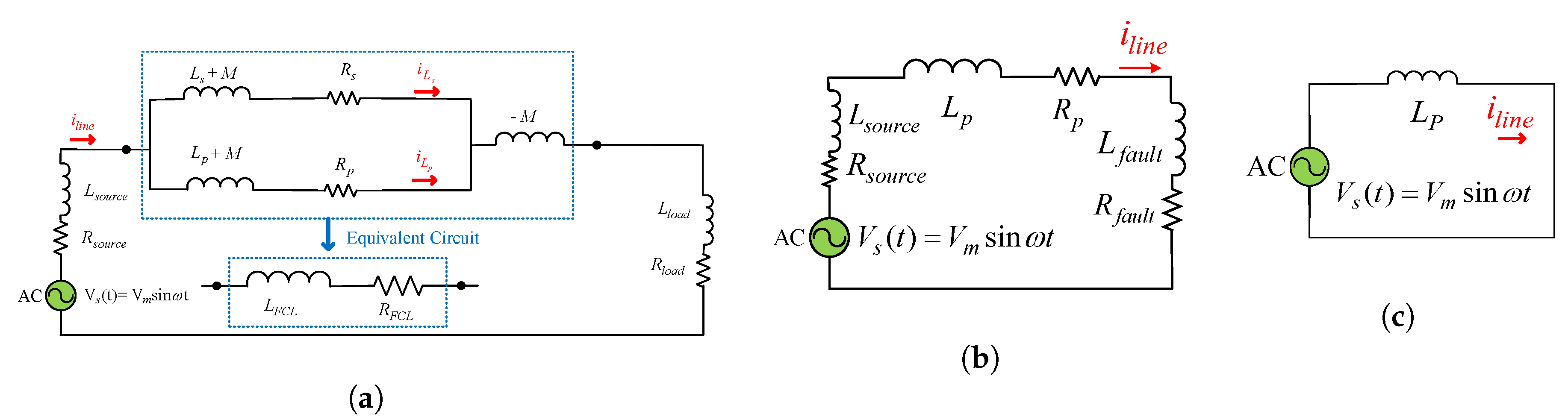
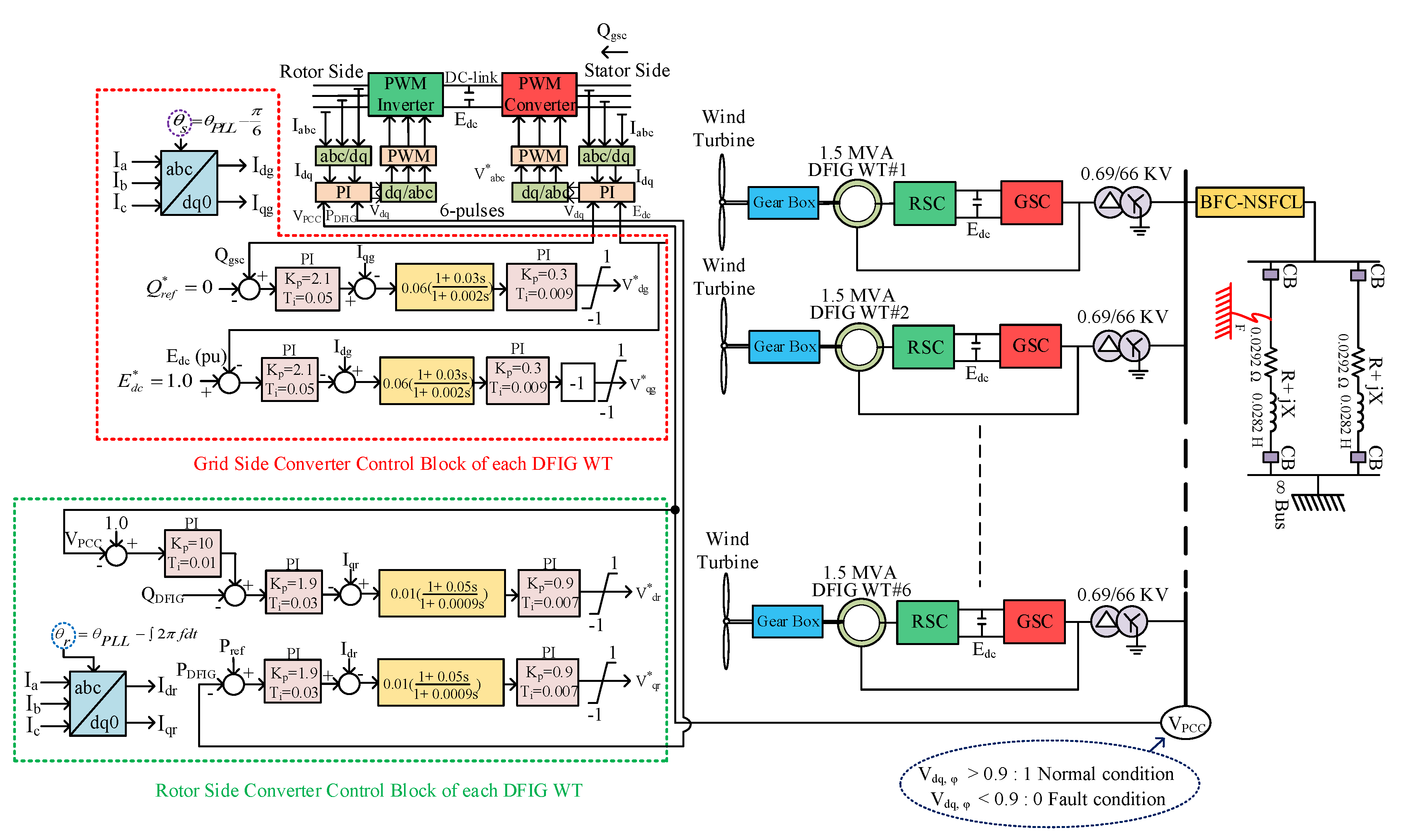
3. System Model
3.1. RSC Controller
3.2. GSC Controller
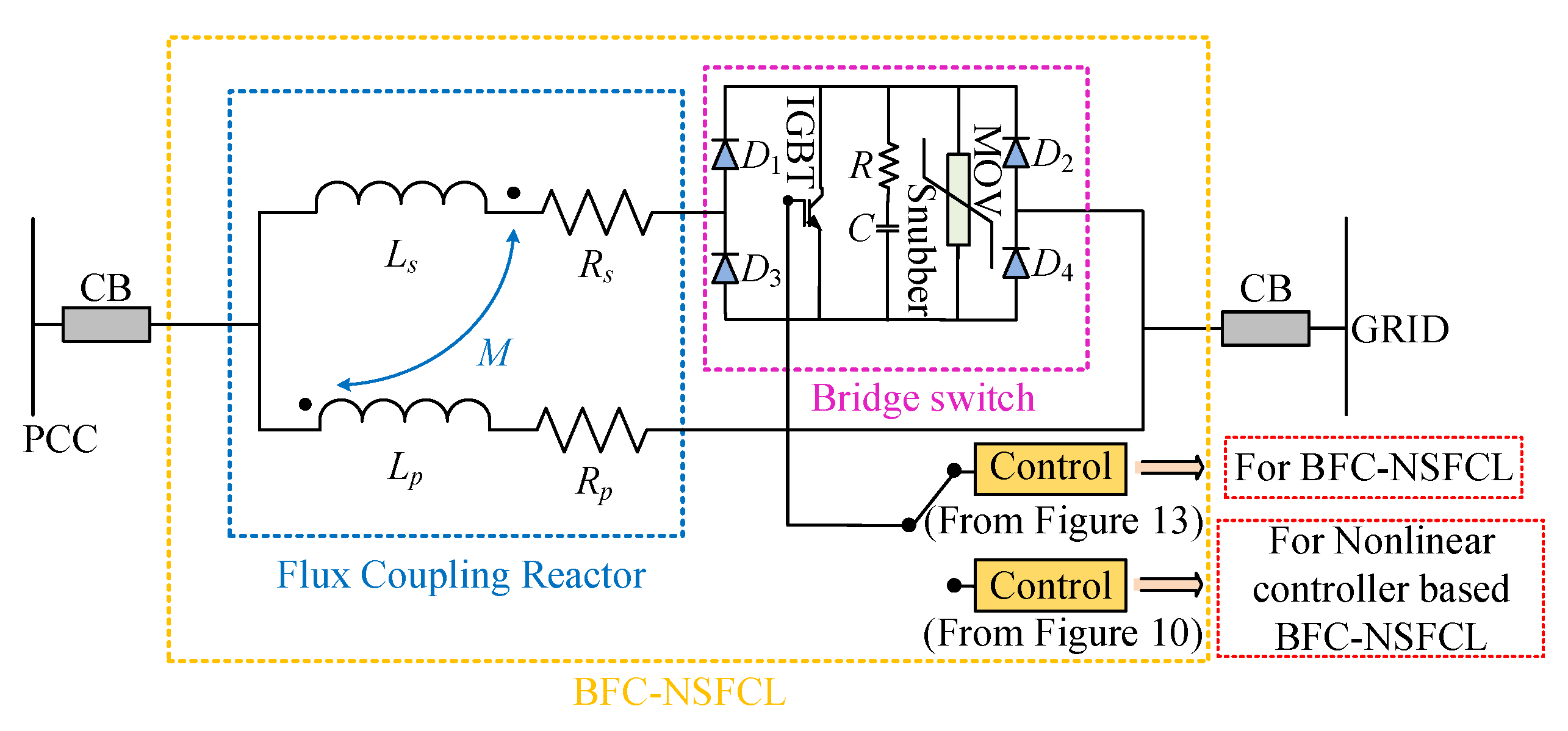
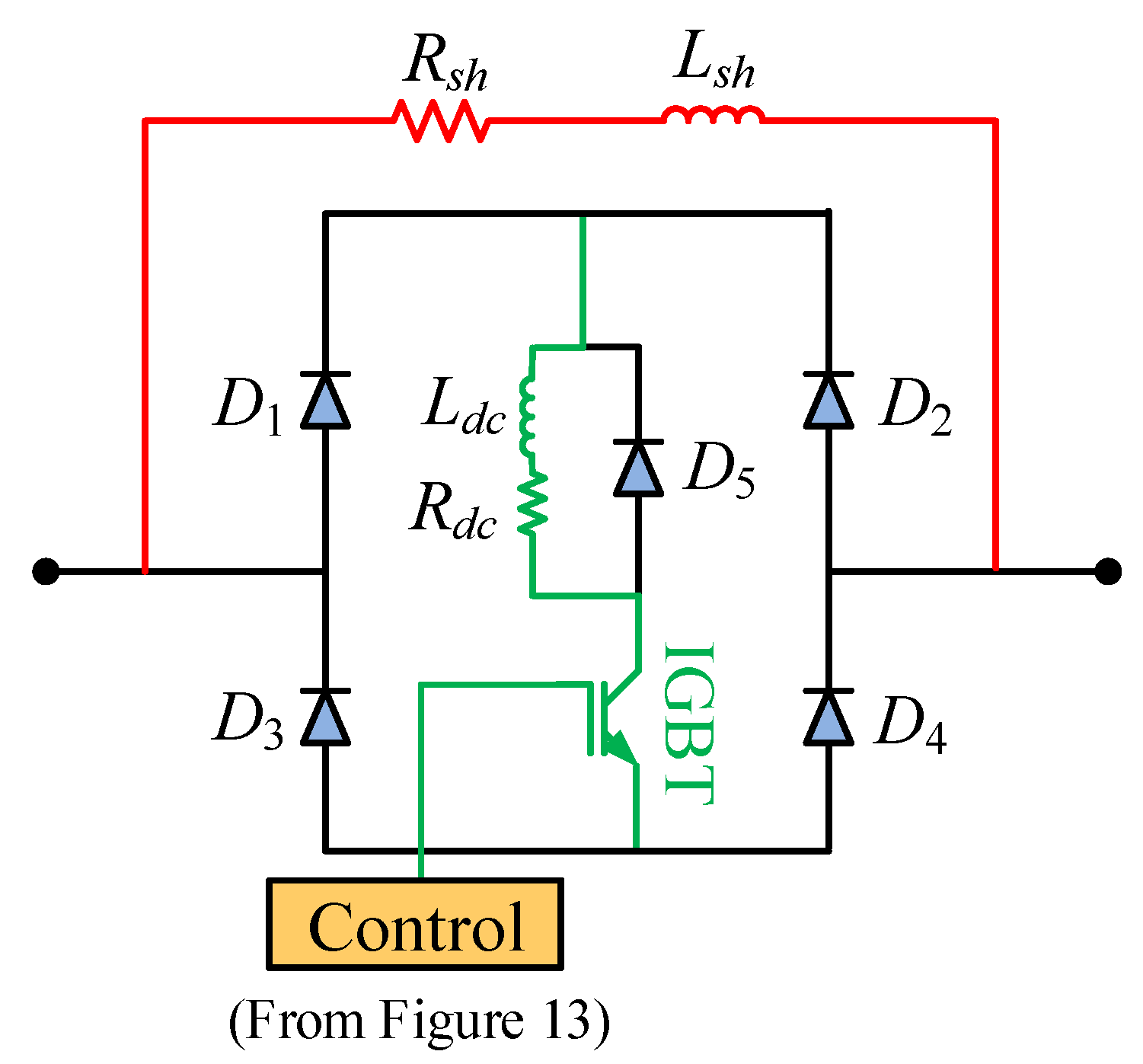
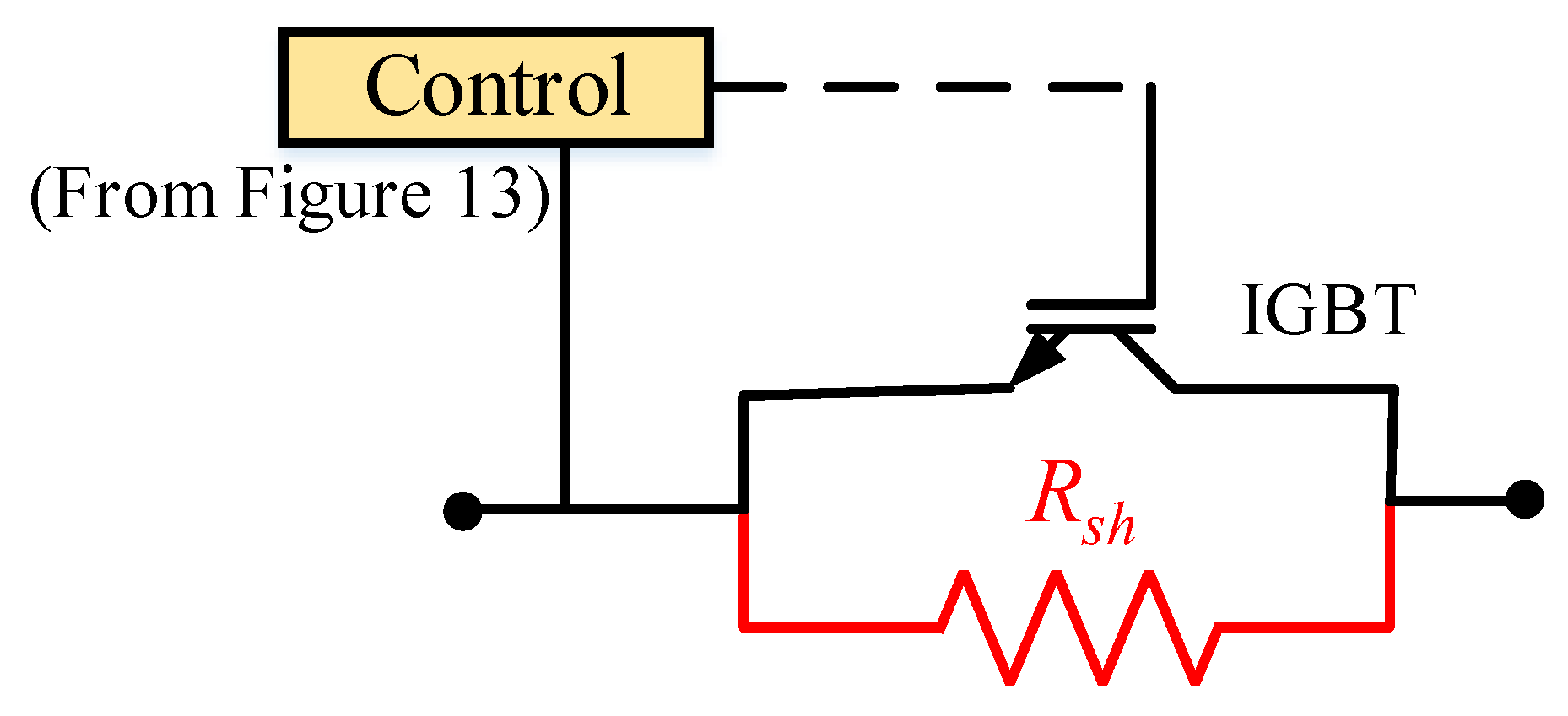
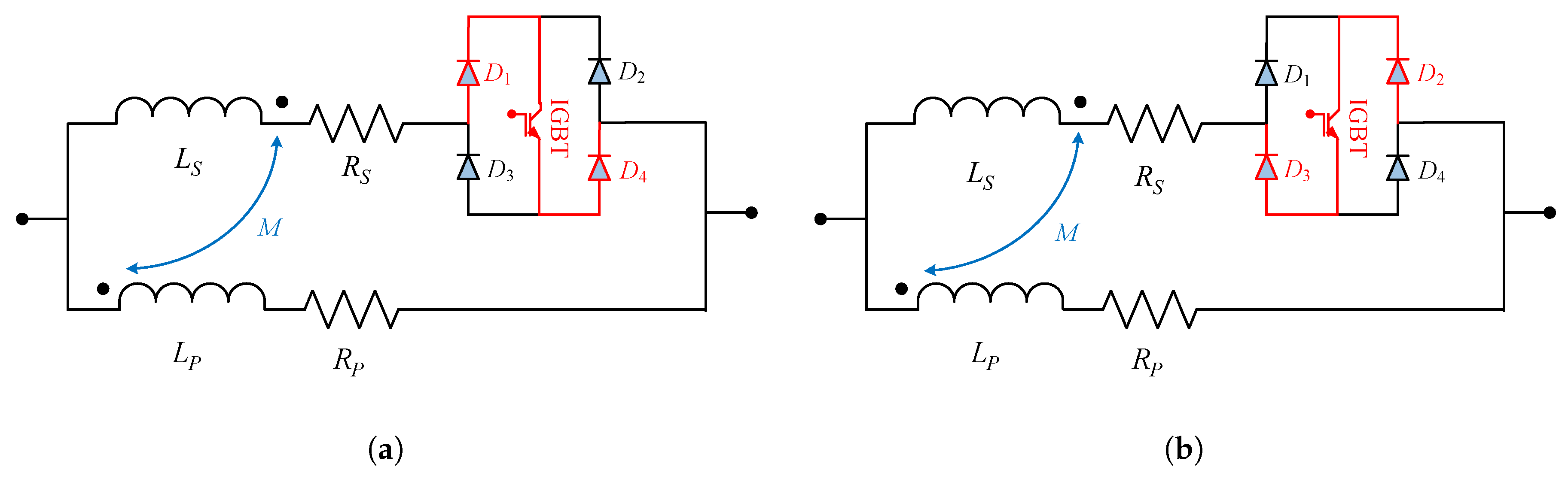
4. Bridge-Type Flux Coupling Non-Superconducting Fault Current Limiter (BFC-NSFCL)
4.1. Construction
4.2. Working Principle
4.2.1. Normal State
4.2.2. Fault State
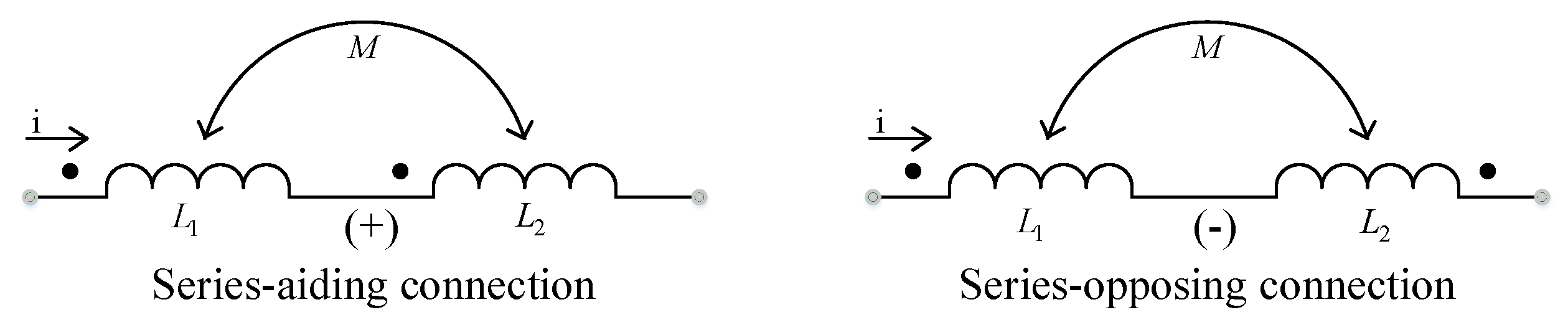
4.3. Theoretical Design Considerations
4.3.1. Normal State
4.3.2. Fault State
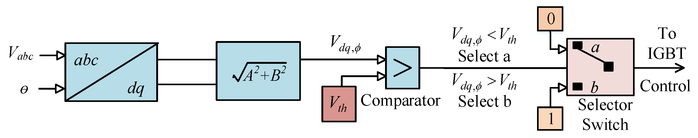
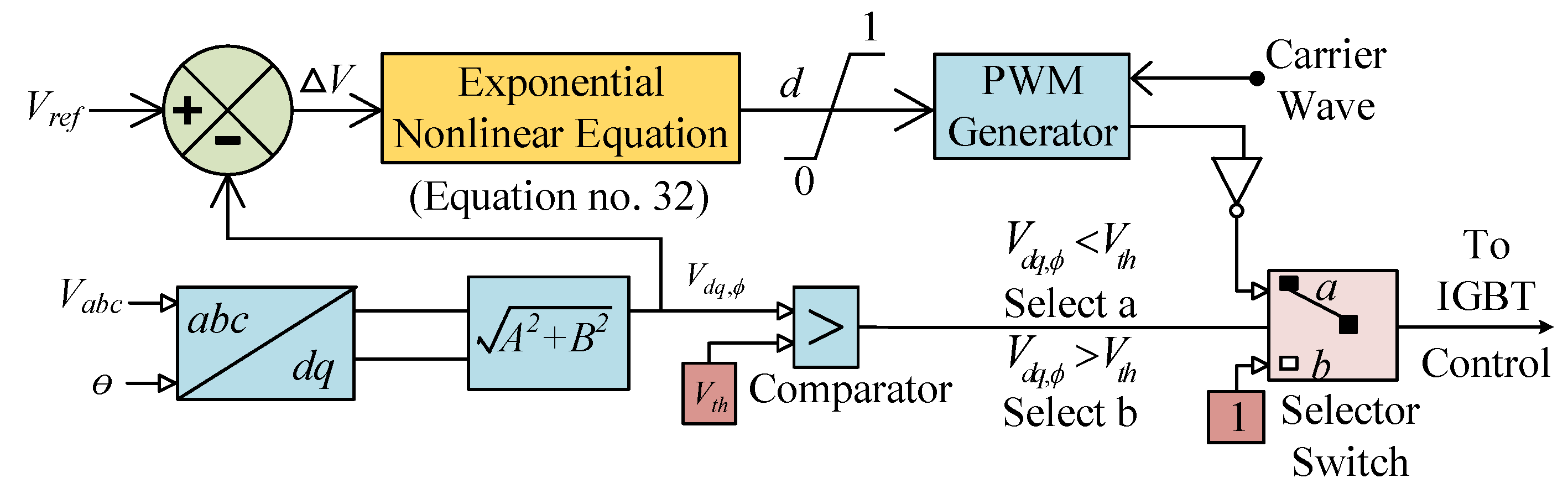
4.4. Proposed Nonlinear Controller for the BFC-NSFCL
5. Bridge-Type Fault Current Limiter (BFCL) and Series Dynamic Braking Resistor (SDBR)
5.1. Construction of the BFCL
5.1.1. Working Principle of the Bridge-Type Fault Current Limiter (BFCL)
5.1.2. Control Scheme for the BFCL
5.1.3. BFCL Design Consideration
5.2. SDBR Construction
Working Principle of the SDBR
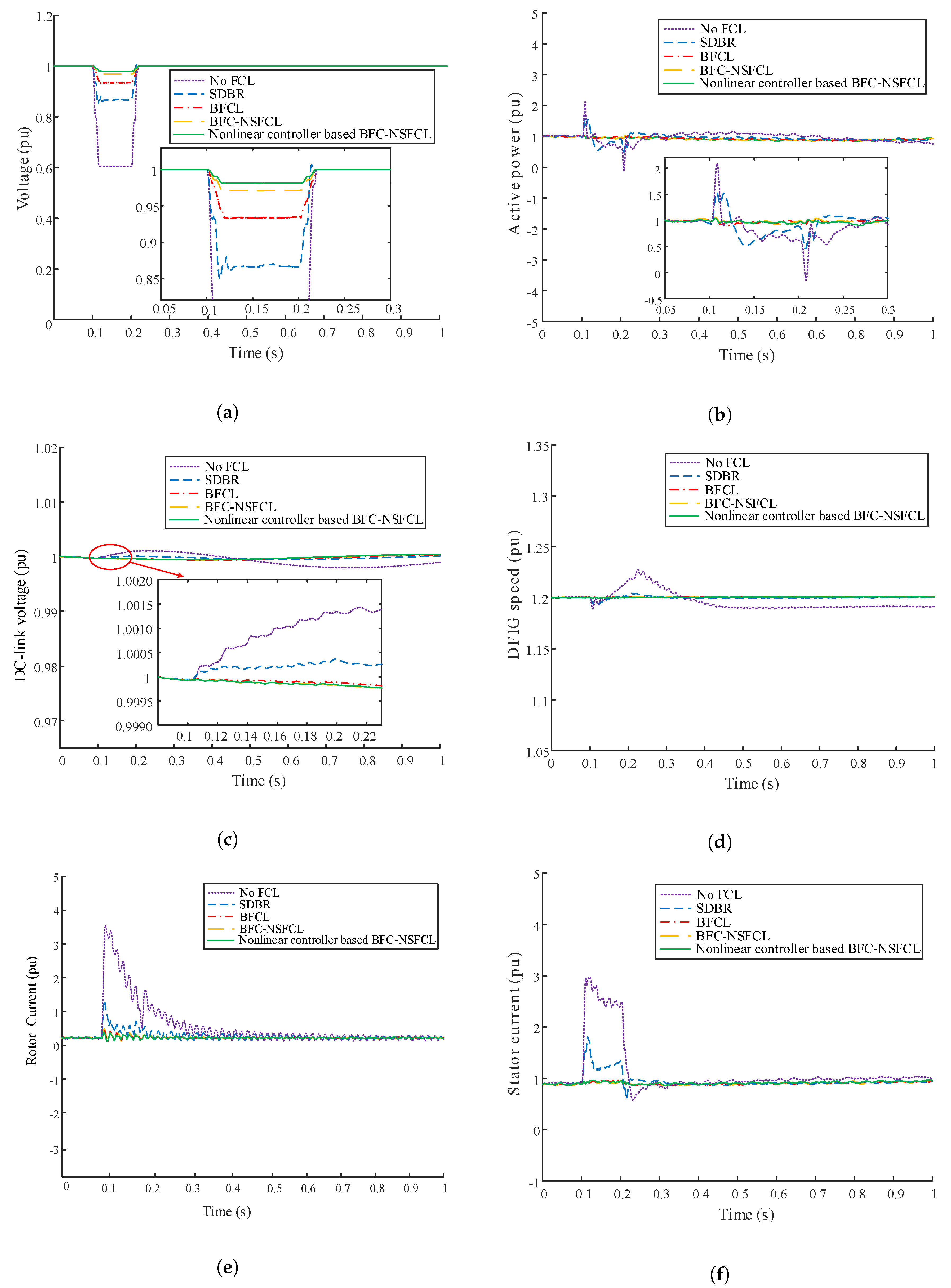
6. Simulation Results and Discussions
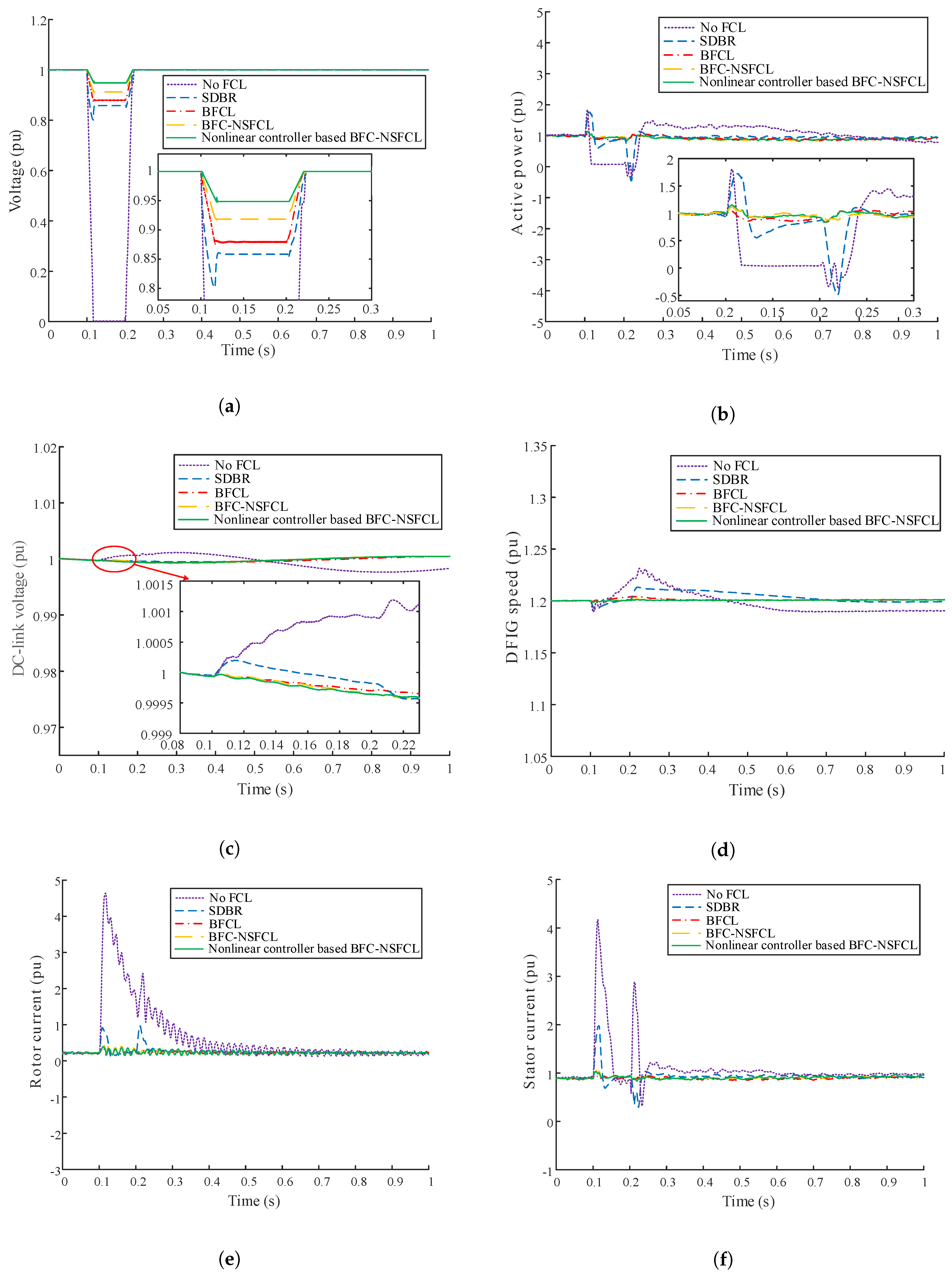
6.1. Temporary Fault Responses
6.1.1. Symmetrical Fault Responses
6.1.2. Unsymmetrical Fault Responses
6.1.3. Index-Based Analysis for Temporary Fault
6.1.4. Steady State Analysis of Temporary Faults
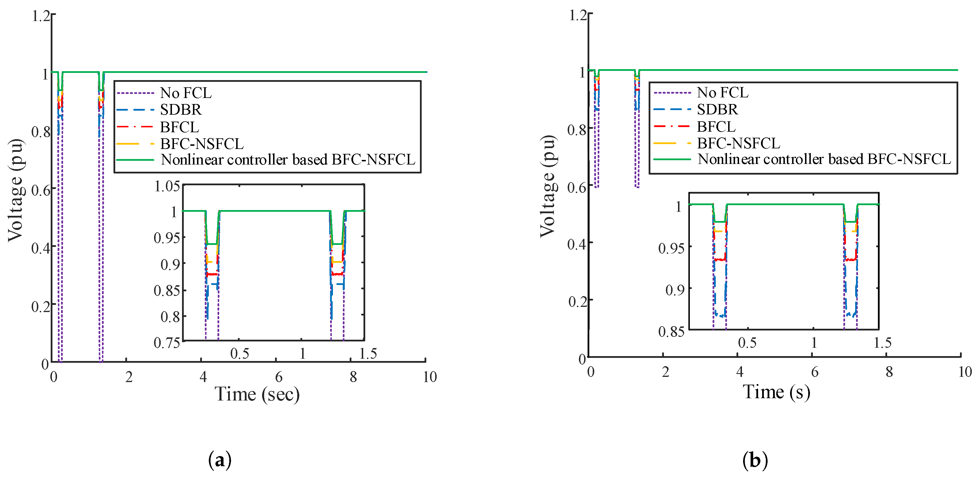
6.2. Permanent Fault Responses
6.2.1. Index Based Analysis for Permanent Fault
6.2.2. Steady State Analysis of Permanent Faults
7. Practical Feasibility and Cost Analysis
8. Conclusions
- Without any FCL, the system experiences substantial consequences during fault.
- The BFC-NSFCL performs superior to that of the BFCL and SDBR under different fault conditions such as subjecting the system to successful and unsuccessful reclosing of the CBs during symmetrical and unsymmetrical grid fault conditions.
- Finally, the nonlinear controller based BFC-NSFCL provides smoother and faster response compared to the BFC-NSFCL without any controller. It also provides swift convergence during steady situation as evident from the better overshoot and settling time parameters.
Author Contributions
Funding
Conflicts of Interest
Abbreviations
| BFC-NSFCL | Bridge-Type Flux Coupling Non-Superconducting Fault Current Limiter |
| BFCL | Bridge-Type Fault Current Limiter |
| FC-SFCL | Flux Coupling Superconducting Fault Current Limiter |
| FCR | Flux Coupling Reactor |
| FRT | Fault Ride Through |
| GSC | Grid Side Converter |
| IGBT | Insulated Gate Bipolar Transistor |
| MFCL | Magnetic Fault Current Limiter |
| MOV | Metal Oxide Varistor |
| NSFCL | Non-Superconducting Fault Current Limiter |
| PCC | Point of Common Coupling |
| RSC | Rotor Side Converter |
| SDBR | Series Dynamic Braking Resistor |
| SFCL | Superconducting Fault Current Limiter |
| SMES | Superconducting Magnetic Energy Storage |
Appendix A

| Parameter | Value |
|---|---|
| Rated power | 1.5 MVA |
| Rated voltage | 0.69 KV |
| DC-link nominal voltage | 1.2 KV |
| DC-link capacitance value | 12,000 F |
| Wind speed | 14 ms |
| Frequency | 50 Hz |
| Resistance of stator | 0.005 pu |
| Magnetizing inductance | 3.95279 pu |
| Leakage inductance of stator | 0.09321 pu |
| Inertia | 0.80 |
| Leakage inductance of wound rotor | 0.09955 pu |
| Wound rotor resistance | 0.0055 pu |
| Friction factor | 0.01 |
References
- Justo, J.J.; Mwasilu, F.; Jung, J.W. Doubly-fed induction generator based wind turbines: A comprehensive review of fault ride-through strategies. Renew. Sustain. Energy Rev. 2015, 45, 447–467. [Google Scholar] [CrossRef]
- Hu, J.; Wang, B.; Wang, W.; Tang, H.; Chi, Y.; Hu, Q. Small signal dynamics of DFIG-based wind turbines during riding through symmetrical faults in weak AC grid. IEEE Trans. Energy Convers. 2017, 32, 720–730. [Google Scholar] [CrossRef]
- Tohidi, S.; Behnam, M.I. A comprehensive review of low voltage ride through of doubly fed induction wind generators. Renew. Sustain. Energy Rev. 2016, 57, 412–419. [Google Scholar] [CrossRef]
- Gounder, Y.K.; Nanjundappan, D.; Boominathan, V. Enhancement of transient stability of distribution system with SCIG and DFIG based wind farms using STATCOM. IET Renew. Power Gener. 2016, 10, 1171–1180. [Google Scholar] [CrossRef]
- Wessels, C.; Gebhardt, F.; Fuchs, F.W. Fault ride-through of a DFIG wind turbine using a dynamic voltage restorer during symmetrical and asymmetrical grid faults. IEEE Trans. Power Electron. 2010, 26, 807–815. [Google Scholar] [CrossRef] [Green Version]
- Pannell, G.; Zahawi, B.; Atkinson, D.J.; Missailidis, P. Evaluation of the performance of a DC-link brake chopper as a DFIG low-voltage fault-ride-through device. IEEE Trans. Energy Convers. 2013, 28, 535–542. [Google Scholar] [CrossRef]
- Morren, J.; De Haan, S.W. Ridethrough of wind turbines with doubly-fed induction generator during a voltage dip. IEEE Trans. Energy Convers. 2005, 20, 435–441. [Google Scholar] [CrossRef] [Green Version]
- Okedu, K.; Muyeen, S.; Takahashi, R.; Tamura, J. Comparative study between two protection schemes for DFIG-based wind generator. In Proceedings of the 2010 International Conference on Electrical Machines and Systems, Incheon, Korea, 10–13 October 2010; pp. 62–67. [Google Scholar]
- Salles, M.; Cardoso, J.; Grilo, A.; Rahmann, C.; Hameyer, K. Control strategies of doubly fed induction generators to support grid voltage. In Proceedings of the 2009 IEEE International Electric Machines and Drives Conference, Miami, FL, USA, 3–6 May 2009; pp. 1551–1556. [Google Scholar]
- Yang, J.; Fletcher, J.E.; O’Reilly, J. A series-dynamic-resistor-based converter protection scheme for doubly-fed induction generator during various fault conditions. IEEE Trans. Energy Convers. 2010, 25, 422–432. [Google Scholar] [CrossRef] [Green Version]
- Qiao, W.; Venayagamoorthy, G.K.; Harley, R.G. Real-time implementation of a STATCOM on a wind farm equipped with doubly fed induction generators. IEEE Trans. Ind. Appl. 2009, 45, 98–107. [Google Scholar] [CrossRef] [Green Version]
- Rashid, G.; Ali, M.H. Fault ride through capability improvement of DFIG based wind farm by fuzzy logic controlled parallel resonance fault current limiter. Electr. Power Syst. Res. 2017, 146, 1–8. [Google Scholar] [CrossRef]
- Hossain, M.K.; Ali, M.H. Transient stability augmentation of PV/DFIG/SG-based hybrid power system by parallel-resonance bridge fault current limiter. Electr. Power Syst. Res. 2016, 130, 89–102. [Google Scholar] [CrossRef]
- Sadi, M.A.H.; Ali, M.H. A comprehensive analysis of transient stability enhancement methods of electric power system. In Proceedings of the 2015 North American Power Symposium (NAPS), Charlotte, NC, USA, 4–6 October 2015; pp. 1–6. [Google Scholar]
- Radmanesh, H.; Fathi, S.H.; Gharehpetian, G.; Heidary, A. Bridge-type solid-state fault current limiter based on AC/DC reactor. IEEE Trans. Power Deliv. 2015, 31, 200–209. [Google Scholar] [CrossRef]
- Shen, H.; Mei, F.; Zheng, J.; Sha, H.; She, C. Three-Phase Saturated-Core Fault Current Limiter. Energies 2018, 11, 3471. [Google Scholar] [CrossRef] [Green Version]
- Alam, M.; Abido, M.; El-Amin, I. Fault current limiters in power systems: A Comprehensive Review. Energies 2018, 11, 1025. [Google Scholar] [CrossRef] [Green Version]
- Yang, Q.; Le Blond, S.; Liang, F.; Yuan, W.; Zhang, M.; Li, J. Design and application of superconducting fault current limiter in a multiterminal HVDC system. IEEE Trans. Appl. Supercond. 2017, 27, 1–5. [Google Scholar] [CrossRef] [Green Version]
- Zou, Z.C.; Xiao, X.Y.; Liu, Y.F.; Zhang, Y.; Wang, Y.H. Integrated protection of DFIG-based wind turbine with a resistive-type SFCL under symmetrical and asymmetrical faults. IEEE Trans. Appl. Supercond. 2016, 26, 1–5. [Google Scholar] [CrossRef]
- Ngamroo, I.; Karaipoom, T. Improving low-voltage ride-through performance and alleviating power fluctuation of DFIG wind turbine in DC microgrid by optimal SMES with fault current limiting function. IEEE Trans. Appl. Supercond. 2014, 24, 1–5. [Google Scholar] [CrossRef]
- Lee, H.J.; Lim, S.H.; Kim, J.C. Application of a Superconducting Fault Current Limiter to Enhance the Low-Voltage Ride-Through Capability of Wind Turbine Generators. Energies 2019, 12, 1478. [Google Scholar] [CrossRef] [Green Version]
- Zou, Z.C.; Chen, X.Y.; Li, C.S.; Xiao, X.Y.; Zhang, Y. Conceptual design and evaluation of a resistive-type SFCL for efficient fault ride through in a DFIG. IEEE Trans. Appl. Supercond. 2015, 26, 1–9. [Google Scholar] [CrossRef]
- Rasolonjanahary, J.; Sturgess, J.; Chong, E.; Baker, A.; Sasse, C. Design and construction of a magnetic fault current limiter. In Proceedings of the 3rd IET International Conference on Power Electronics, Machines and Drives-PEMD, Dublin, Ireland, 4–6 April 2006; IET: London, UK, 2006; pp. 681–685. [Google Scholar]
- Qu, L.; Zeng, R.; Yu, Z.; Li, G. Design and test of a magnetic saturation-type fault current limiter. J. Eng. 2019, 2019, 2974–2979. [Google Scholar] [CrossRef]
- Yuan, J.; Zhong, Y.; Lei, Y.; Tian, C.; Guan, W.; Gao, Y.; Muramatsu, K.; Chen, B. A novel hybrid saturated core fault current limiter topology considering permanent magnet stability and performance. IEEE Trans. Magn. 2017, 53, 1–4. [Google Scholar] [CrossRef]
- Tseng, H.T.; Jiang, W.Z.; Lai, J.S. A Modified Bridge Switch-Type Flux-Coupling Nonsuperconducting Fault Current Limiter for Suppression of Fault Transients. IEEE Trans. Power Deliv. 2018, 33, 2624–2633. [Google Scholar] [CrossRef]
- Rashid, G.; Ali, M.H. Transient stability enhancement of doubly fed induction machine-based wind generator by bridge-type fault current limiter. IEEE Trans. Energy Convers. 2015, 30, 939–947. [Google Scholar] [CrossRef]
- Sadi, M.A.H.; Ali, M.H. A fuzzy logic controlled bridge type fault current limiter for transient stability augmentation of multi-machine power system. IEEE Trans. Power Syst. 2015, 31, 602–611. [Google Scholar] [CrossRef]
- Rashid, G.; Ali, M.H. Application of parallel resonance fault current limiter for fault ride through capability augmentation of DFIG based wind farm. In Proceedings of the IEEE/PES Transmission and Distribution Conference and Exposition (T&D), Dallas, TX, USA, 2–5 May 2016; pp. 1–5. [Google Scholar]
- Firouzi, M.; Gharehpetian, G.B. LVRT performance enhancement of DFIG-based wind farms by capacitive bridge-type fault current limiter. IEEE Trans. Sustain. Energy 2017, 9, 1118–1125. [Google Scholar] [CrossRef]
- Kartijkolaie, H.S.; Radmehr, M.; Firouzi, M. LVRT capability enhancement of DFIG-based wind farms by using capacitive DC reactor-type fault current limiter. Int. J. Electr. Power Energy Syst. 2018, 102, 287–295. [Google Scholar] [CrossRef]
- Naderi, S.; Davari, P.; Zhou, D.; Negnevitsky, M.; Blaabjerg, F. A Review on Fault Current Limiting Devices to Enhance the Fault Ride-Through Capability of the Doubly-Fed Induction Generator Based Wind Turbine. Appl. Sci. 2018, 8, 2059. [Google Scholar] [CrossRef] [Green Version]
- Rashid, G.; Ali, M.H. A modified bridge-type fault current limiter for fault ride-through capacity enhancement of fixed speed wind generator. IEEE Trans. Energy Convers. 2014, 29, 527–534. [Google Scholar]
- Causebrook, A.; Atkinson, D.J.; Jack, A.G. Fault ride-through of large wind farms using series dynamic braking resistors. IEEE Trans. Power Syst. 2007, 22, 966–975. [Google Scholar] [CrossRef]
- Soliman, M.A.; Hasanien, H.M.; Azazi, H.Z.; El-Kholy, E.E.; Mahmoud, S.A. Hybrid ANFIS-GA-based control scheme for performance enhancement of a grid-connected wind generator. IET Renew. Power Gener. 2018, 12, 832–843. [Google Scholar] [CrossRef]
- Rashid, G.; Ali, M.H. Nonlinear control-based modified BFCL for LVRT capacity enhancement of DFIG-based wind farm. IEEE Trans. Energy Convers. 2016, 32, 284–295. [Google Scholar] [CrossRef]
- Le, V.; Li, X.; Li, Y.; Dong, T.; Le, C. An innovative control strategy to improve the fault ride-through capability of DFIGs based on wind energy conversion systems. Energies 2016, 9, 69. [Google Scholar] [CrossRef]
- Okedu, K.E.; Muyeen, S.; Takahashi, R.; Tamura, J. Wind farms fault ride through using DFIG with new protection scheme. IEEE Trans. Sustain. Energy 2012, 3, 242–254. [Google Scholar] [CrossRef] [Green Version]
- Lopez, J.; Sanchis, P.; Roboam, X.; Marroyo, L. Dynamic behavior of the doubly fed induction generator during three-phase voltage dips. IEEE Trans. Energy Convers. 2007, 22, 709–717. [Google Scholar] [CrossRef]
- Sadi, M.A.H.; Ali, M.H. Lyapunov Function Controlled Parallel Resonance Fault Current Limiter for Transient Stability Enhancement of Power System. In Proceedings of the 2018 North American Power Symposium (NAPS), Fargo, ND, USA, 9–11 September 2018; pp. 1–6. [Google Scholar]
- Sadi, M.A.H.; Ali, M.H. Maintaining Distribution Protective Relay Coordination By Sliding Mode Control Based Bridge Type Fault Current Limiter. In Proceedings of the 2019 IEEE Power & Energy Society General Meeting (PESGM), Atlanta, GA, USA, 4–8 August 2019; pp. 1–5. [Google Scholar]
- Yan, S.; Ren, L.; Wang, Z.; Yang, Z.; Xu, Y.; Chen, L.; Yu, B.; Tang, Y.; Liang, S. Simulation analysis and experimental tests of a small-scale flux-coupling type superconducting fault current limiter. IEEE Trans. Appl. Supercond. 2016, 27, 1–5. [Google Scholar] [CrossRef]
- Pei, X.; Smith, A.C.; Barnes, M. Superconducting fault current limiters for HVDC systems. Energy Procedia 2015, 80, 47–55. [Google Scholar] [CrossRef]


| M | K | ||||
|---|---|---|---|---|---|
| 1.56 | 250 mH | 0.21 | 350 mH | 292.84 mH | 0.99 |
| 20 | 250 mH | 0.003 | 1 mH |
| Index Parameters (%) | Values of Indices | ||||
|---|---|---|---|---|---|
| No FCL | SDBR | BFCL | BFC-NSFCL | Nonlinear Controller Based BFC-NSFCL | |
| vlt(pu.s) | 10.145 | 1.614 | 1.241 | 0.993 | 0.681 |
| pow(pu.s) | 27.327 | 12.281 | 7.151 | 6.165 | 6.112 |
| dclink(pu.s) | 0.112 | 0.037 | 0.034 | 0.032 | 0.028 |
| spd(pu.s) | 0.869 | 0.442 | 0.101 | 0.073 | 0.050 |
| rtr(pu.s) | 46.838 | 4.739 | 2.135 | 2.092 | 2.065 |
| str(pu.s) | 21.706 | 18.148 | 2.655 | 2.604 | 2.386 |
| Index Parameters (%) | Values of Indices | ||||
|---|---|---|---|---|---|
| No FCL | SDBR | BFCL | BFC-NSFCL | Nonlinear Controller Based BFC-NSFCL | |
| vlt(pu.s) | 3.982 | 1.314 | 0.670 | 0.319 | 0.212 |
| pow(pu.s) | 11.808 | 8.483 | 3.057 | 2.566 | 2.106 |
| dclink(pu.s) | 0.101 | 0.036 | 0.031 | 0.028 | 0.027 |
| spd(pu.s) | 0.291 | 0.086 | 0.058 | 0.047 | 0.034 |
| rtr(pu.s) | 34.220 | 3.245 | 1.754 | 1.685 | 1.583 |
| str(pu.s) | 18.462 | 6.977 | 2.006 | 1.862 | 1.751 |
| Percentage Overshoot | Settling Time (s) | |||||||||
|---|---|---|---|---|---|---|---|---|---|---|
| FCLs | Active Power | DC-Link Voltage | DFIG Speed | Rotor Current | Stator Current | Active Power | DC-Link Voltage | DFIG Speed | Rotor Current | Stator Current |
| No FCL | 44.884 | 0.133 | 2.158 | 95.150 | 79.424 | 12.838 | ∞ | 16.915 | 4.754 | 1.744 |
| SDBR | 43.531 | 0.051 | 0.967 | 76.859 | 55.683 | 0.645 | 2.562 | 5.334 | 0.581 | 0.935 |
| BFCL | 8.263 | 0.048 | 0.210 | 36.387 | 6.798 | 0.178 | 1.079 | 0.134 | 0.572 | 0.585 |
| BFC-NSFCL | 6.063 | 0.043 | 0.065 | 27.279 | 2.411 | 0.111 | 0.613 | 0.051 | 0.531 | 0.542 |
| Nonlinear controller | ||||||||||
| based BFC-NSFCL | 5.483 | 0.040 | 0.010 | 25.619 | 1.961 | 0.105 | 0.534 | 0.046 | 0.339 | 0.253 |
| Percentage Overshoot | Settling Time (s) | |||||||||
|---|---|---|---|---|---|---|---|---|---|---|
| FCLs | Active Power | DC-Link Voltage | DFIG Speed | Rotor Current | Stator Current | Active Power | DC-Link Voltage | DFIG Speed | Rotor Current | Stator Current |
| No FCL | 53.405 | 0.132 | 2.049 | 93.685 | 71.016 | 11.252 | 12.984 | 15.192 | 2.975 | 0.974 |
| SDBR | 34.248 | 0.049 | 0.474 | 83.028 | 51.382 | 0.506 | 4.168 | 0.269 | 0.395 | 0.751 |
| BFCL | 10.029 | 0.048 | 0.032 | 49.288 | 9.374 | 0.456 | 0.934 | 0.066 | 0.273 | 0.418 |
| BFC-NSFCL | 9.492 | 0.045 | 0.030 | 45.237 | 8.818 | 0.073 | 0.554 | 0.045 | 0.210 | 0.386 |
| Nonlinear controller | ||||||||||
| based BFC-NSFCL | 5.443 | 0.044 | 0.029 | 36.504 | 8.462 | 0.051 | 0.498 | 0.033 | 0.183 | 0.242 |
| Index Parameters (%) | Values of Indices | ||||
|---|---|---|---|---|---|
| No FCL | SDBR | BFCL | BFC-NSFCL | Nonlinear Controller Based BFC-NSFCL | |
| vlt(pu.s) | 20.266 | 3.226 | 2.491 | 1.993 | 1.294 |
| pow(pu.s) | 65.942 | 32.846 | 22.871 | 19.397 | 16.745 |
| dclink(pu.s) | 0.882 | 0.175 | 0.146 | 0.111 | 0.099 |
| spd(pu.s) | 14.675 | 4.437 | 3.148 | 3.088 | 2.966 |
| rtr(pu.s) | 108.096 | 23.375 | 15.094 | 14.666 | 13.921 |
| str(pu.s) | 55.758 | 42.689 | 23.925 | 21.476 | 18.112 |
| Index Parameters (%) | Values of Indices | ||||
|---|---|---|---|---|---|
| No FCL | SDBR | BFCL | BFC-NSFCL | Nonlinear Controller Based BFC-NSFCL | |
| vlt(pu.s) | 7.955 | 2.534 | 1.296 | 0.633 | 0.459 |
| pow(pu.s) | 25.895 | 18.848 | 7.985 | 5.459 | 5.284 |
| dclink(pu.s) | 0.207 | 0.104 | 0.059 | 0.056 | 0.053 |
| spd(pu.s) | 10.848 | 3.489 | 1.486 | 1.349 | 1.255 |
| rtr(pu.s) | 75.949 | 15.895 | 7.386 | 6.386 | 5.898 |
| str(pu.s) | 38.848 | 20.846 | 8.488 | 7.885 | 7.579 |
| Overshoot | Settling Time | |||||||||||||||||||
|---|---|---|---|---|---|---|---|---|---|---|---|---|---|---|---|---|---|---|---|---|
| FCLs | Active Power | DC-Link Voltage | DFIG Speed | Rotor Current | Stator Current | Active Power | DC-Link Voltage | DFIG Speed | Rotor Current | Stator Current | ||||||||||
| 1st sag | 2nd sag | 1st sag | 2nd sag | 1st sag | 2nd sag | 1st sag | 2nd sag | 1st sag | 2nd sag | 1st sag | 2nd sag | 1st sag | 2nd sag | 1st sag | 2nd sag | 1st sag | 2nd sag | 1st sag | 2nd sag | |
| No FCL | 49.693 | 46.460 | 0.099 | 0.299 | 2.201 | 1.534 | 94.592 | 94.607 | 79.059 | 77.400 | N/A | 14.146 | N/A | ∞ | N/A | 21.264 | N/A | 4.980 | N/A | 1.989 |
| SDBR | 48.571 | 42.857 | 0.065 | 0.082 | 1.381 | 1.397 | 77.619 | 76.766 | 56.699 | 56.410 | 0.649 | 0.827 | N/A | 2.747 | N/A | 6.267 | 0.622 | 0.808 | N/A | 0.988 |
| BFCL | 17.279 | 17.883 | 0.041 | 0.038 | 1.194 | 1.291 | 33.030 | 36.012 | 9.285 | 13.354 | 0.205 | 0.319 | N/A | 1.098 | 1.057 | 0.238 | 0.597 | 0.741 | 0.718 | 0.774 |
| BFC-NSFCL | 16.123 | 16.589 | 0.027 | 0.030 | 0.908 | 1.153 | 31.544 | 31.917 | 6.491 | 10.901 | 0.158 | 0.163 | 0.636 | 0.737 | 0.102 | 0.111 | 0.564 | 0.660 | 0.603 | 0.619 |
| Nonlinear controller | ||||||||||||||||||||
| based BFC-NSFCL | 15.174 | 15.572 | 0.015 | 0.017 | 0.249 | 0.332 | 23.219 | 26.275 | 3.519 | 5.869 | 0.105 | 0.151 | 0.619 | 0.668 | 0.032 | 0.036 | 0.314 | 0.321 | 0.242 | 0.250 |
| Overshoot | Settling Time | |||||||||||||||||||
|---|---|---|---|---|---|---|---|---|---|---|---|---|---|---|---|---|---|---|---|---|
| FCLs | Active Power | DC-Link Voltage | DFIG Speed | Rotor Current | Stator Current | Active Power | DC-Link Voltage | DFIG Speed | Rotor Current | Stator Current | ||||||||||
| 1st sag | 2nd sag | 1st sag | 2nd sag | 1st sag | 2nd sag | 1st sag | 2nd sag | 1st sag | 2nd sag | 1st sag | 2nd sag | 1st sag | 2nd sag | 1st sag | 2nd sag | 1st sag | 2nd sag | 1st sag | 2nd sag | |
| No FCL | 56.710 | 52.731 | 0.100 | 0.299 | 1.961 | 3.459 | 92.954 | 92.928 | 70.175 | 69.986 | N/A | 11.998 | N/A | ∞ | N/A | 19.247 | N/A | 4.906 | N/A | 1.906 |
| SDBR | 36.215 | 28.571 | 0.070 | 0.090 | 1.631 | 1.647 | 66.216 | 66.799 | 42.098 | 37.362 | 0.513 | 0.687 | N/A | 2.747 | N/A | 5.677 | 0.583 | 0.717 | N/A | 1.291 |
| BFCL | 17.582 | 18.404 | 0.020 | 0.040 | 0.753 | 0.835 | 45.887 | 46.467 | 9.188 | 14.055 | 0.474 | 0.196 | N/A | 1.118 | 0.129 | 0.212 | 0.425 | 0.614 | 0.548 | 0.649 |
| BFC-NSFCL | 16.974 | 17.355 | 0.015 | 0.017 | 0.374 | 0.514 | 39.173 | 41.589 | 2.857 | 3.519 | 0.085 | 0.101 | 0.566 | 0.922 | 0.071 | 0.185 | 0.334 | 0.549 | 0.462 | 0.532 |
| Nonlinear controller | ||||||||||||||||||||
| based BFC-NSFCL | 16.512 | 16.821 | 0.010 | 0.010 | 0.125 | 0.200 | 38.575 | 40.191 | 1.392 | 2.746 | 0.054 | 0.058 | 0.518 | 0.884 | 0.065 | 0.114 | 0.297 | 0.509 | 0.339 | 0.421 |
© 2020 by the authors. Licensee MDPI, Basel, Switzerland. This article is an open access article distributed under the terms and conditions of the Creative Commons Attribution (CC BY) license (http://creativecommons.org/licenses/by/4.0/).
Share and Cite
Islam, M.R.; Huda, M.N.; Hasan, J.; Sadi, M.A.H.; AbuHussein, A.; Roy, T.K.; Mahmud, M.A. Fault Ride Through Capability Improvement of DFIG Based Wind Farm Using Nonlinear Controller Based Bridge-Type Flux Coupling Non-Superconducting Fault Current Limiter. Energies 2020, 13, 1696. https://doi.org/10.3390/en13071696
Islam MR, Huda MN, Hasan J, Sadi MAH, AbuHussein A, Roy TK, Mahmud MA. Fault Ride Through Capability Improvement of DFIG Based Wind Farm Using Nonlinear Controller Based Bridge-Type Flux Coupling Non-Superconducting Fault Current Limiter. Energies. 2020; 13(7):1696. https://doi.org/10.3390/en13071696
Chicago/Turabian StyleIslam, Md. Rashidul, Md. Najmul Huda, Jakir Hasan, Mohammad Ashraf Hossain Sadi, Ahmed AbuHussein, Tushar Kanti Roy, and Md. Apel Mahmud. 2020. "Fault Ride Through Capability Improvement of DFIG Based Wind Farm Using Nonlinear Controller Based Bridge-Type Flux Coupling Non-Superconducting Fault Current Limiter" Energies 13, no. 7: 1696. https://doi.org/10.3390/en13071696