Article

Simulation Test of a DC Fault Current Limiter for Fault Ride-Through Problem of Low-Voltage DC Distribution

School of Electrical and Electronics Engineering, State Key Laboratory of Alternate Electrical Power System with Renewable Energy Sources, North China Electric Power University, Baoding 071003, Hebei, China
*
Authors to whom correspondence should be addressed.
Energies 2020, 13(7), 1753; https://doi.org/10.3390/en13071753
Submission received: 15 February 2020 / Revised: 8 March 2020 / Accepted: 1 April 2020 / Published: 6 April 2020
(This article belongs to the Section F: Electrical Engineering)

Abstract

:
The low voltage direct current (LVDC) distribution networks are connected with too many kinds of loads and sources, which makes them prone to failure. Due to the small damping value in the DC lines, the fault signal propagates so fast that the impact current with the wave front of millisecond and the transient voltage pose great challenges for fault detection. Even worse, some faults with small currents are difficult to detect and the communication is out of sync, resulting in protection misoperation. These problems have severely affected the new energy utilization. In view of this, a DC fault current limiter (FCL) composed of inductance, resistance, and power electronic switch was designed in this paper. The rising speed of fault current can be decreased by the series inductance and the peak value of the fault current can be limited by series impedance, thus in this way the running time can be gained for fault detection and protection. For distributed energy access, by deducing the short circuit fault characteristic expression of LVDC distribution network, the feasibility of FCL was verified. Based on the structure of the bridge-type alternating current (AC) current limiter, the structure and parameters of the DC FCL were determined according to the fault ride-through target. Then, a low voltage ride-through strategy based on DC FCL was proposed for the bipolar short-circuit fault of LVDC distribution network. Finally, MATLAB/Simulink simulation was used to verify the rationality of the proposed FCL and its ride-through strategy.

1. Introduction

With the application of large quantities of direct current (DC) equipment and the increasing access and utilization of various distributed energy sources, DC distribution networks have a broad application prospect [1,2]. The DC distribution systems based on two-level voltage source converters (VSC) are suitable for access to distributed generation and DC load with fast and independent active or reactive power control, and they have abilities such as black start, multiterminal network structure expansion and rapid reduction of interference, making them widely applied in middle and low voltage industries [3]. However, the transient characteristics of VSC caused by the fault are accompanied by the rapidly increasing DC fault current, and the poor overload capacity of the power electronic converter affects its stability [4]. With the increase of the installed capacity, North American Electric Reliability Corporation and the workgroup member of Institute of Electrical and Electronic Engineers (IEEE) took full consideration of the high permeability of distributed power supply and required the fault ride-through ability for distributed power supply to support the stable operation of the power grid [5,6]. Therefore, it is necessary to enhance the fault ride-through capability of DC distribution network with distributed power supply.
Currently, there are few studies on the fault ride-through of distributed power supply in the field of LVDC distribution network [7,8,9]. In Emhemed et al. [7] the advanced local measurement and communication technology were adopted in a smart LVDC power grid, and some solid-state circuit breakers were controlled by some intelligent electronic device relays to realize fault limiting as well as fast and reliable recovery during the transient. In this paper, the suppression for the fault current of 2 kA within two milliseconds required a delay greater than one millisecond. In such condition, the reliability was difficult to be guaranteed. In addition, the influence of the disturbance on the detection and location was not considered, and it lacks indepth research for the ride-through scheme of blocking the large fault current and realizing controllable reclosing after failure through diodes in two-way control switches. In Chen et al. [8], a resistance-type superconductor current limiter was adopted to realize fault current-limiting and bus-bar voltage compensation in the DC system so as to lower the quick-acting requirements and design difficulty for DC fault protection scheme. This scheme is quite advanced; however, there is little study about fault ride-through based on current limiting function, and the maintenance cost for the resistance-type superconductor current limiter is high. In Li et al. [9] a solid-state circuit breaker with automatic and rapid fault current-limiting was developed to realize riding-through. However, there are few mature products of low-cost high-speed high capacity LVDC circuit breaker with the time scale of microsecond, and the device reliability is relatively low. In the AC power transmission and distribution systems [10,11,12] and high voltage direct current (HVDC) transmission field [13,14], the fault detection and protection devices are widely applied. Based on the characteristics of the transient current component such as current zero, DC voltage jump and change, the fault ride-through can be realized by network segmentation and reconstruction or adopting a high impedance transformer. However, the detection and protection devices for HVDC transmission system and AC system cannot satisfy the relay protection requirements of the LVDC power distribution system; furthermore, the equivalent system model of HVDC system is not completely suitable for LVDC distribution system for transient analysis. Therefore, it is urgent to study the transient process and the fault ride-through technologies for the distributed power supply based on VSC.
In order to solve the problem of quick fault suppression and detection in LVDC distribution systems and realize the protection and fault ride-through, the following work has been done in this paper: firstly, the fault characteristic expressions of DC distribution network connected by a variety of distributed power sources were derived to preliminarily explore the feasibility of the proposed fault ride-through measures. According to the requirements and characteristics, the structure of DC current limiter was designed and the data ranges of components were determined. Then a fault ride-through scheme based on DC fault current-limiting (FCL) was proposed. For the LVDC distribution network composed of photovoltaic, AC power supply and DC load, the rationality of the proposed FCL was verified by MATLAB/Simulink simulation.
This paper is arranged as follows: in Section 2, the LVDC distribution network structure was given and fault transient characteristics of expression was derived in detail. In accordance with the requirements of ride-through and protection, in Section 3 the FCL structure and its components were presented. In Section 4, the protection of FCL and the ride-through coordination strategy were illustrated in detail. In Section 5, the performance of FCL and coordination strategy was validated by simulation. In Section 6, some conclusions were drawn.

2. Fault of LVDC Distribution Network

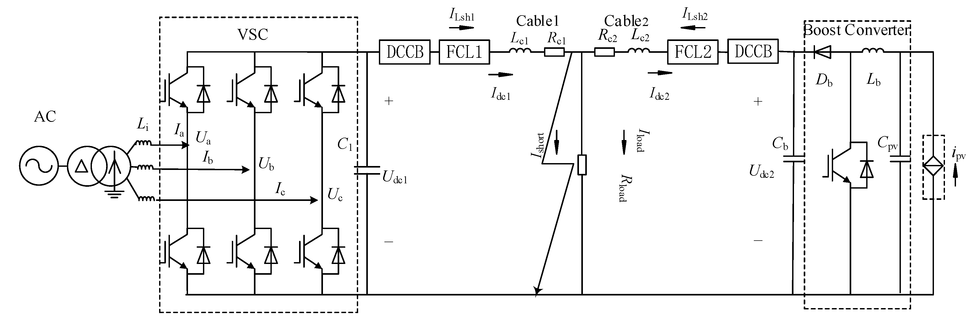
2.1. LVDC Distribution Network Structure and Fault Location

For different components such as bus bars, circuit breakers and lines, there are a variety of connecting modes for the typical structure for the access of distributed energy to LVDC distribution network. The star-connected and ring-connected structures are the basic topologies, which can derive many complex topologies, such as tree radiation and mesh network [15]. Figure 1 shows the structure of a star-connected LVDC distribution network. The system is connected to the AC power grid by a fully controlled power electronic interface (mainly composed of a VSC based on insulated gate bipolar transistors) and a transformer. VSCs can not only control DC voltage and bidirectional power, but they also deal with power grid disturbance. Photovoltaic cells are connected to the DC bus through DC/DC booster converter, and photovoltaic power systems can improve the generation efficiency through the maximum power point tracking control. The direct-drive permanent magnet synchronous generator is connected to the DC bus through sinusoidal pulse width modulation controlled VSC1 and the cable. The battery energy storage system is connected to the DC bus through a two-way chopper. On the load side, a DC/DC or DC/AC converter acts as the power module to provide the required voltage for different load applications.
According to the fault position with respect to the VSC converter [16], the faults of DC distribution systems can be roughly divided into the following types: 1) Faults on AC side: VSCs are widely used as AC-DC or DC-AC converters for power conversion. In fact, the AC side fault of grid-connected inverter has been taken into account when designing the protection scheme. 2) Internal failure: internal failure of VSC includes failure of power electronic devices, such as insulated gate bipolar transistor (IGBT), etc., which can protect the system by providing backup converters or redundant devices. 3) DC network fault: DC short circuit fault is the most serious fault of VSCs. In this case, IGBTs may be blocked from self-protection, and the large VSC filter capacitor and low impedance cable may cause overcurrent or undervoltage, so the fault protection and ride-through make use of the FCL installed in the DC network. According to the study in References [17,18,19,20], when there is a short circuit between the positive and negative electrodes of the DC line, a pole-pole fault occurs with low fault impedance. When the positive or negative terminal of a DC line is ground short-circuited, a pole-ground fault occurs, accompanied by a low impedance fault or a high impedance fault. The location of these faults is either in the DC bus or in one of the DC cables, as F1–F10 in Figure 1. F1–F4 and F5–F8 respectively represent the pole-pole faults and pole-ground faults of the DC cable, while F9–F10 represent the pole-pole faults and pole-ground faults of the DC bus, respectively. Compared with these two faults, although the pole-ground fault is more likely to occur, the current and voltage caused by the ground fault is far less serious than the DC bipolar short-circuit fault. Moreover, when the single-pole bus ground fault occurs, the DC switch can quickly disconnect the fault and restore the load power supply through the nonfault pole bus. Therefore, this paper takes the connection of photovoltaic power system to LVDC network as an example to deduce the analytical expression of the fault characteristic of bipolar short circuit in the system (limited by space, the derivation is described in detail by Shuai et al., Monjo et al., Emhemed et al., Yang et al. [17,18,19,20]; so as to provide a basis for the proposed FCL structure and parameter design.

2.2. Fault Characteristics of LVDC Distribution Network with Photovoltaic Power System

The equivalent circuit of a pole-pole short-circuit fault for DC distribution network with distributed power supply is shown in Figure 2, from which the short-circuit fault characteristics of the network can be deduced. The photovoltaic unit is connected to the DC bus by a booster converter, where Rc1, Lc1, Rc2 and Lc2 are the π-type equivalent resistance and inductance of the positive and negative cables. From the VSC and boost converter to the fault position, due to the larger DC bus capacitance C1, the grounding capacitance of the cable can be ignored. In fault analysis, considering the fault resistance is far less than the load resistance Rload, the load resistance Rload can be neglected as well.
The fault response process is divided into the following three stages:
1.
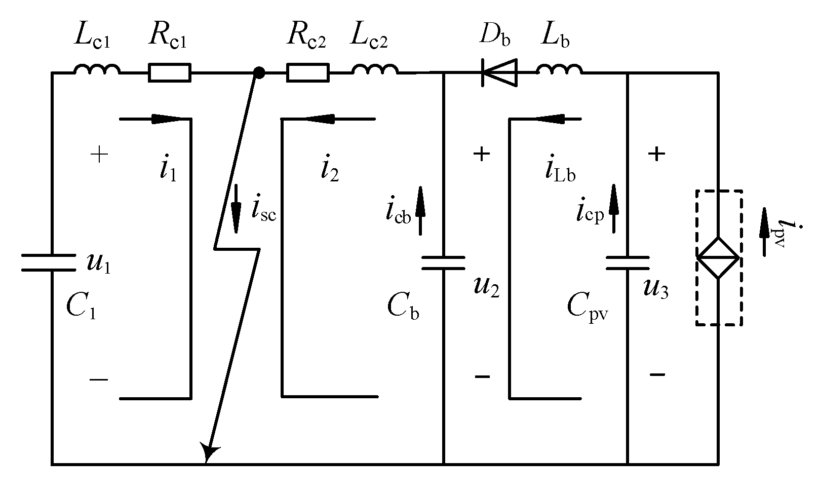
The equivalent circuit of DC capacitance discharging stage is shown in Figure 3.
The fault process is dominated by C1 on the VSC side and Cb of the booster converter. For a bigger C1 than Cb, the discharge time constant τ = RC; when they are approximately equal, the discharge time of C1 will be greater than that of Cb. Assume that failure occurs at the time t0, and the steady-state bus voltage and initial cable current of the two converters on DC side are
{ u 1 ( t 0 ) = u 2 ( t 0 ) = V dc i 1 ( t 0 ) = V dc R c 2 / ( R c 1 R c 2 + R c 2 R load + R c 1 R load ) i 2 ( t 0 ) = V dc R c 1 / ( R c 1 R c 2 + R c 2 R load + R c 1 R load )
Applying Kirchhoff Voltage laws (KVL) to the circuit consisted of Rc1, Lc1 and the DC bus capacitance C1 yields:
d 2 i 1 ( t ) d t 2 + R c 1 L c 1 d i 1 ( t ) d t + i 1 ( t ) L c 1 C 1 = 0
The corresponding solution of (2) is (3).
i 1 ( t ) = A 1 cos ( ω c 1 t ) e α c 1 t + A 2 sin ( ω c 1 t ) e α c 1 t
where,
  • ω c 1 = ( 1 / ( L c 1 C 1 ) ( R c 1 / 2 L c 1 ) 2 ) 1 / 2 ,
  • α c 1 = R c 1 / 2 L c 1 ,
  • A 2 = ω c 1 [ ( V dc R c 1 A 1 ) / L c 1 + α c 1 A 1 ] ,
  • A 1 = i 1 ( t 0 ) .
The moment i1 reaches maximum can be calculated by (4).
t i 1 ( max ) = 1 ω c 1 arctan ( A 2 ω c 1 A 1 α c 1 A 1 ω c 1 + A 2 α c 1 )
The moment that voltage of the capacitance C1 drops to zero is:
t 1 = t 0 + 1 ω c 1 [ π arctan ( V dc C 1 sin β V dc C 1 cos β L c 1 C 1 i 1 ( t 0 ) ) ]
where,
  • β = arctan ( 4 L c 1 / ( R c 1 2 C 1 ) 1 ) 1 / 2 .
Applying Kirchhoff Current laws (KCL) to the circuit consisted of Cpv, Lb and Db yields:
i 2 ( t ) = i cb ( t ) + i Lb ( t ) = i cb ( t ) + i cp ( t ) + i pv
At this moment, icb, icp and ipv are the discharge current of Cb and Cpv and the photovoltaic cell equivalent current, respectively.
Applying KCL to the circuit consisted of Cb, Rc2 and Lc2 yields:
d 2 i cb ( t ) d t 2 + R c 2 L c 2 d i cb ( t ) d t + i cb ( t ) L c 2 C b = 0
The differential equation can be solved as follows:
i cb ( t ) = B 1 cos ( ω cb t ) e α cb t + B 2 sin ( ω cb t ) e α cb t
where,
  • ω cb = ( 1 / ( L c 2 C b ) ( α cb ) 2 ) 1 / 2 , B 1 = i cb ( t 0 ) , B 2 = ω cb [ ( V dc R c 2 B 1 ) / L c 2 + α cb B 1 ] , α cb = R c 2 / 2 L c 2
Applying Kirchhoff Voltage laws (KVL) to the circuit consisted of Cpv, Lb, Rc2, Lc2 and ignoring the voltage drop on Lb produced by ipv yield:
d 2 i cp ( t ) d t 2 + R c 2 L 1 d i cp ( t ) d t + i cp ( t ) L 1 C pv = i cb ( t ) L 1 C b
The differential equation can be solved as follows:
i cp ( t ) = D 1 cos ( ω cp t ) e α cp t + D 2 sin ( ω cp t ) e α cp t + D 3 cos ( ω cb t ) e α cb t + D 4 sin ( ω cb t ) e α cb t
where,
  • L 1 = L c 2 + L b , ω cp = 1 / ( L 1 C pv ) ( α cp ) 2
  • D 1 = i c p ( t 0 ) , D 2 = ω cp [ ( V dc R c 2 D 1 ) / L 1 + α cp D 1 ]
  • α cp = R c 2 / 2 L 1 , D 3 = C pv R c 2 C b ( α cb 2 ω cb ) + C pv B 1 C b L 1 ( α cb 2 + ω cb 2 ) + R c 2 C b α cb
  • D 4 = C pv R c 2 C b ( ω cb 2 α cb ) + C pv B 2 C b L 1 ( α cb 2 + ω cb 2 ) + R c 2 C b ω cb
The diode Db of the booster converter will experience a large transient current at this stage which will quickly damage this diode.
2.
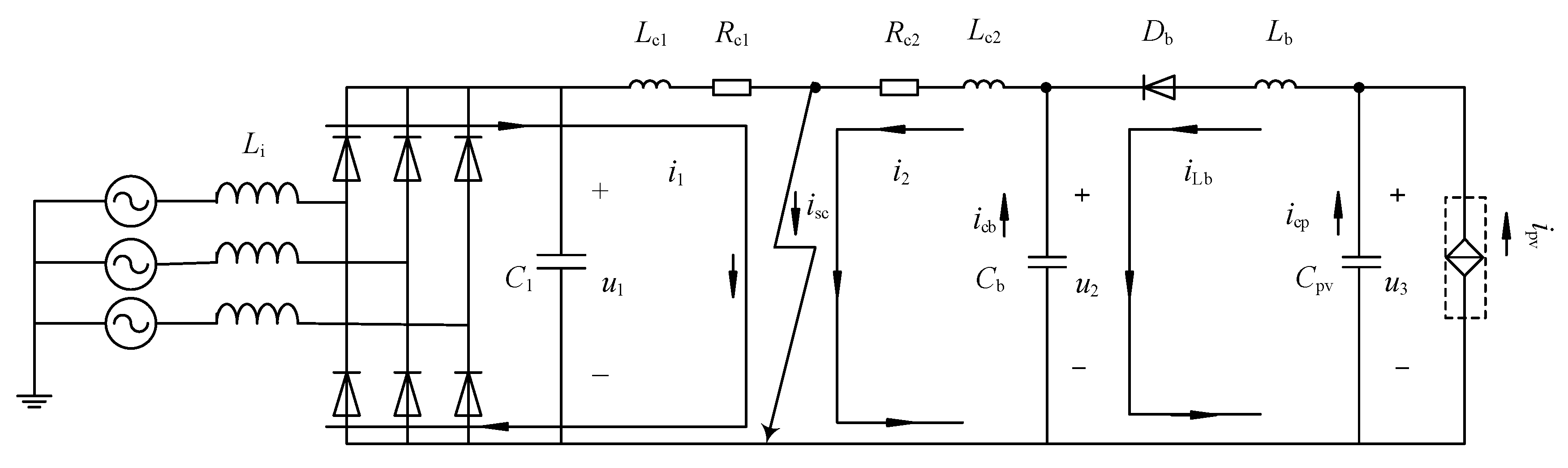
Free-conducting stage of diode: During the discharge process of C1, the electrical energy will change to electromagnetic energy and be stored in the DC side inductance. Its drive current of the reverse electromotive force flows through the VSC bridge commutating diodes of each phase. When the capacitor voltage C1 reaches zero, the equivalent circuit of the stage is demonstrated in Figure 4.
The current and the voltage of C1 are always zero. Under the action of the conduction diode, the cable current i1on the VSC side is one third that of the current flowing through the conduction diode of each phase bridge, i.e.,
{ i 1 = I 1 e ( R c 1 / L c 1 ) t i D 1 = i D 2 = i D 3 = i 1 ( t ) / 3
The initial value of i1 is shown in (3).
According to (6), in the photovoltaic power system, the transient short circuit current i 2 will flow through the fault point and continue to discharge in the form of oscillation. According to (11), it is an important phase for the free-conducting diode of the VSC, for its current i 1 will mutate largely, which can quickly damage it.
3.
Steady state: When the inductance discharge on the DC side ends, the current on the grid side will flow through the diode into the DC side. The equivalent circuit of this state is shown in Figure 5.
At this stage, the short-circuit fault current comes from the AC grid. A three-phase short-circuit current is obtained by the analysis. The phase currents, namely iga, igb and igc flow into the DC side through the corresponding bridge, while the currents on the AC side are under the rectified state without any control.
i VSC = i ga ( > 0 ) + i gb ( > 0 ) + i gc ( > 0 )
According to (6), in the photovoltaic power system, the transient short circuit current i2 is damped oscillation. The three-phase AC power supply and the photovoltaic power unit provide the fault current through the uncontrolled rectifier circuit and the booster circuit respectively. In addition, the amplitude of the fault current in this stage is significantly smaller than that in the previous two stages.

2.3. Fault Analysis of LVDC Distribution Network with Photovoltaic Power System

Based on the fault characteristics of the LVDC distribution network connected to the photovoltaic power system, the following information can be obtained.
1.
Peak current and its arrival time
According to [17,18,19,20], when a small-resistance short-circuit fault happens, the voltage across the capacitance of the photovoltaic booster converter drops to zero within 0.627 ms, while the time for the voltage of C1 droping to zero is about 3.1 ms. Since the voltage across the capacitance is close to the rated bus voltage, the fault current isc will approach the value larger than i1 and the time for the fault current i2 to reach the peak is far less than that of i1. In addition, i2 has a higher peak than i1. In the first stage, the peak value of fault current is the highest and the time is the shortest.
According to (3), the initial amplitude of the fault current is composed of A1, A2 and e−αc1t. Among them, A1 is the rated current at the steady state before the fault occurs, and it is not a big number. Because the time interval of the moment of failure is very small, the term e−αc1t approaches 1 where αc1=Rc1/2Lc1, a numerically large value due to the small value of Lc1, and the value of Lc1C1 is small, resulting in a big value of ωc1, a big αc1 and ωc1 make a numerically large A2, so the amplitude of the fault current is mainly determined by the second coefficient in (3).
According to (4), ti1(max) is in proportion to 1/ωc1 and y = arctan(x) is a numerical value in the interval of (−π/2, π/2). This is because the big value of ωc1, ti1(max) is rather small, which means the time for the fault current to reach the peak is quite short.
2.
Continuity condition for three fault response
According to the fault response analysis in the three stages, the converter is locked after the fault, and the power supply on the AC side and the photovoltaic side is disconnected. In the first stage, the capacitance releases energy storage into the inductance. When the voltage of the capacitance is zero, it stops releasing energy. In the second stage, the current flowing through the inductance follows the VSC side reverse diode. Since there is always the magnetic field energy released by the inductance consumed by the impedance in the discharge circuit, when the energy storage in the inductance is small, the power grid will discharge through the diode until the inductance discharge process on the DC side ends. Thus, the rapid release of capacitor-stored energy is the first condition for the continuity of the three stages.
In the pole-pole short circuit fault, the fault resistance Rfault is generally small, thus C(Rc + Rfault)2/4Lc < 1. According to this, the fault response is an underdamped oscillation process. Moreover, the first-stage transient process of the three stages is the most severe (the fault current may reach thousands of amperes in 2 ms). Therefore, it is in the other continuous conditions that the fault resistance meets the condition of underdamped oscillation.
From the perspective of fault protection and fault ride-through, some measures should be taken in the first stage of fault response. On the one hand, the release rate (rise rate of the current and its amplitude) of capacitance-stored energy needs to be reduced; on the other hand, the condition that C(Rc + Rfault)2/4Lc > 1 should be satisfied to ensure the fault current response in the state of overdamping attenuation and protect the sensitive device of the fault branch. At this point, the voltage of the DC bus parallel capacitance will not drop to zero quickly, and the transient fluctuation is within the acceptable range. The latter two stages will also be avoided.
3.
Countermeasures
To realize the fault ride-through, two measures should be taken in the first stage of the short-circuit fault to reduce the damage and break the continuity condition of the fault response. The first is to extend the time when the fault current reaches the peak (delay its rising speed) so as to facilitate the fault detection and protection operation; the second is to limit the amplitude of the fault current (protect the sensitive devices) so as to provide the guarantee for the recovery operation after the fault disappears. Theoretically, it is possible to achieve by increasing the capacitance discharge time constant and the fault circuit resistance.
According to (3), the current of capacitance energy release observes the law of e−t/τ, where τ = L/R. Therefore, the capacitance discharge time constant can be increased by increasing the inductance of the discharge circuit. According to (5), the increase of the inductance of the discharge circuit may also increase the value of 1/ωc1, resulting in an increment in the time of the C1 voltage dropping to zero. Due to the design, the FCL is connected in series in the circuit, thus it is unfavorable to add a series of resistance which will increase loss. Besides, it works at the DC steady state, and the appropriate increase of inductance will not affect the stable operation but reduce the coefficient of the second term A2. So, with the application of a series of inductance, the capacitance discharge time can be prolonged and the discharge speed can be reduced. In such way, the requirement of delaying the rise speed of the impact current can be met.
According to (3), the decrease of e−αc1t can reduce the amplitude of the fault current rapidly. That is to increase the value that αc1 = Rc1/2Lc1, which can be realized by adding a large resistance in series into the circuit to limit the amplitude of the fault current.
When the DC system runs under steady condition, the application of series inductance for current limiting can effectively prolong the rise time of fault current and reduce its rise rate. After that, at the moment the appropriate current is found, the large resistance circuit is connected to limit the amplitude of the fault current. When the fault disappears, the current-limiting circuit is reconnected and the system resumes normal operation. All these functions can be realized by appropriate design of DC FCL.

3. Design of FCL

3.1. Structure of FCL

The FCLs can be divided into superconducting current limiter, solid-state FCL (solid-state current limiter) and electromagnetic FCL [21,22,23]. During normal operation, it works in a negligible impedance state; while in the failure mode, the high impedance is connected to inhibit the fault current. These two modes can be switched quickly.
The application object is the LVDC power distribution network with complex structure and various control strategy whose lines are short and damping is small. It is prone to failure and the failure propagation speed is rather fast. In the event of fault, the fault current will rise to a dozen times or even one hundred times that of the rated current within two milliseconds, which seriously threatens the safety operation of sensitive devices and their protection performance. In addition to general current limiting function, four other functions are required. First, the current limiting works at the same time as the fault occurs, and there is no need for detection. If the detection, operation and high-speed DC circuit breaker are added, the reliability of protection and quick action are difficult to meet. Secondly, the current limiting function should be first operated to protect the sensitive devices by suppressing the impact currents caused by rapid disturbances on the one hand, while on the other hand it can provide sufficient time for detection and execution devices (such as fault detection, signal acquisition, signal transmission, information processing, switch and converter control, and DC protection devices) or the others. Thirdly, during the process, the energy storage in the inductance needs to be released to restore the capacity. Fourthly, for the current fluctuation caused by impact load or motor start, FCL is not needed.
Therefore, the configuration principle of FCLs in this paper is as follows: First, in order to avoid current limiting caused by startup, the power electronic switch (antiparallel IGBT, etc.) is closed on startup to short-circuit the FCL and then disconnected after it operates normally. Secondly, at steady state, the FCL is connected to the DC distribution network in series. Since the fault location is uncertain, the position should be located at the connection joint between the parallel capacitance and the line cable on the DC side of the distributed power supply or the connection joint between the DC bus and the line cable, so as to suppress the impact current caused by rapid disturbance and protect the sensitive devices. Thirdly, during the operation of current limiting, when the fault current exceeds two times the rated one, the circuit is switched to the large-resistance-limiting circuit. Fourthly, the energy dissipation circuit should be deployed for the current-limiting inductance to recover its current limiting capability before another failure.
The proposed structure of direct current fault current limiter (DC FCL) is shown in Figure 6.
In Figure 6, Lsh is the current-limiting inductance, Rsh is the internal resistance of Lsh, Rrse is the leak resistance, D is the energy release circuit diode, and Lsh is the limiting resistor. Table 1 shows the switch logic functions of DC FCL.
Function of switch state logic: K1, K2, K3 and K4 are the four switches for the four-state realization of fault ride-through. Before the distribution system starting, K1 is closed to make the FCL short-circuit to avoid the protection and switch action caused by the large current fluctuation at the start of the impact load. K1 is switched off and K2 is closed after the system operates normally. The current-limiting circuit is connected in series to the lines to prevent the overshoot of the impact current in real time. When the fault current reaches 2IN, the K2 is disconnected and K3 is closed, and the amplitude of fault current is limited in the range of 50% IN-IN. During failure, K4 is closed while K2 is disconnected. In the amplitude-limiting process, the current-limiting inductance discharges through the loop of Lsh-rsh-Rrse-D and thus its current-limiting capacity is recovered.

3.2. Parameter Design of FCL

The FCL designed in this paper is used to realize the fault ride-through when the bipolar short circuit occurs in the LVDC distribution lines, while the faults inside the converter and on the AC side are not involved, and normal operation should be restored immediately after the failure. Thus, the parameter design should consider these two operation modes. In the failure mode, the safe operation of the sensitive devices should be ensured and designed according to the analysis above; in the normal operation mode, we should refer to the standards. Due to the fact that it is installed at the outlet of parallel capacitor or the bus, every power outlet should have its own inductance and resistance.
1.
Design of Lsh
The design principle is to suppress the instantaneous overshoot of the fault at the initial stage. Due to the short interval between the early failure and failure, the designed current limiting and amplitude limiting interval should be short too, because the current-limiting inductance Lsh cannot be too large (when the volume is too large, too much energy storage causes overvoltage, and the current reducing the system response speed is too slow, etc.). Therefore, the effect of current-limiting inductance is to delay the rising speed of impact current and prolong the time when the impact current reaches the peak but not to change the peak value of impact current. Among them, the maximum value of Lsh,max should satisfy the overdamped oscillation condition during normal operation, that is, L < (R2C/4); the minimum value of Lsh,min should be larger than the value that can withhold the fault current calculated by (3) and (6). It should be pointed out that the current should not break down the capacitance at the output terminal on the DC side. The most serious failure situation should be checked: a bipolar metallic short circuit occurred between the FCL connected in series at the parallel capacitor end and the connection point of the cable line, that is, Rfault = 0.
2.
Design of Rrse
The simplest design principle is to quickly release the energy stored by the current-limiting inductance and restore its current limiting capability through a diode and a small resistor.
The resistance for energy release is related to the recovery time of current-limiting inductance, and the allowed maximum time interval should refer to the time from the access of the amplitude-limiting Rsh to the disconnection. In practice, the time should be designed according to the most serious fault and the shortest time interval between two faults.

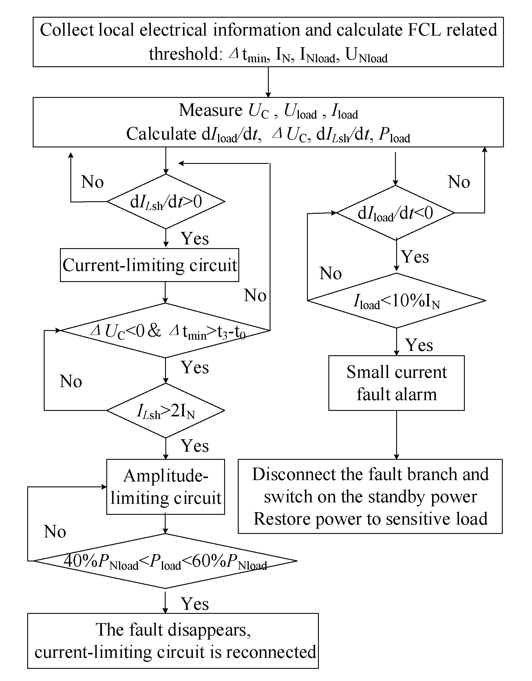
4. Fault Protection and Ride-Through Strategy Based on FCL

Based on the proposed DC FCL, the fault protection and ride-through of LVDC system can be realized, and the flowchart is depicted in Figure 7. In case of permanent failure, the differential protection is used as the FCL backup protection and the DC circuit breaker is disconnected at both ends of the line. In Figure 7, Δtmin > t3 − t0, which means a longer duration of the voltage drop of the parallel capacitor than that of the fault when a short circuit occurs at the connection between the line terminal and the FCL. It shows 40% PNload < Pload < 60% PNload, which means that the measured power on the load is within ±10% of half of the rated load power.

5. Simulation

5.1. Simulation Model

In order to verify the feasibility of the proposed fault ride-through strategy, the DC FCL was connected to the LVDC distribution network containing photovoltaic power generation system, as shown in Figure 8. The corresponding simulation model was built in MATLAB/Simulink, and the simulation was conducted before and after the occurrence of bipolar short-circuits in the middle of the 1km distribution line. The detailed parameters of the simulation model are listed in Table 2.
In the figure, ILsh1and ILsh2 are the currents in the current-limiting inductances; Idc1and Idc2 are the DC line currents on the VSC side and boost converter side, respectively; Iload and Ishort are the currents in the load resistance and short-circuit resistance; Udc1 and Udc2 are the bus voltage on the C1 side and Cb side, respectively.
In the simulation, the bipolar short circuit fault is divided into two categories: the type of large current (Idc ≥ 2IN) and the type of small current (Idc < 2IN), as shown in Figure 9 and Figure 10 and Figure 11 and Figure 12. The whole simulation process lasted for four seconds, in which 0 s–1 s was the starting process of the distribution network, and after that, the system went into normal operation. During the interval of 1 s to 2 s, the system operated normally. At 2 s, the bipolar short circuit occurred. During 2 s–4 s, the fault proceeded. After 4 s, the limiter circuit was switched back to the current-limiting circuit and stable operation was resumed if the fault disappeared; otherwise, for permanent fault, the DC circuit breaker of the fault branch should be disconnected for fault alarm.

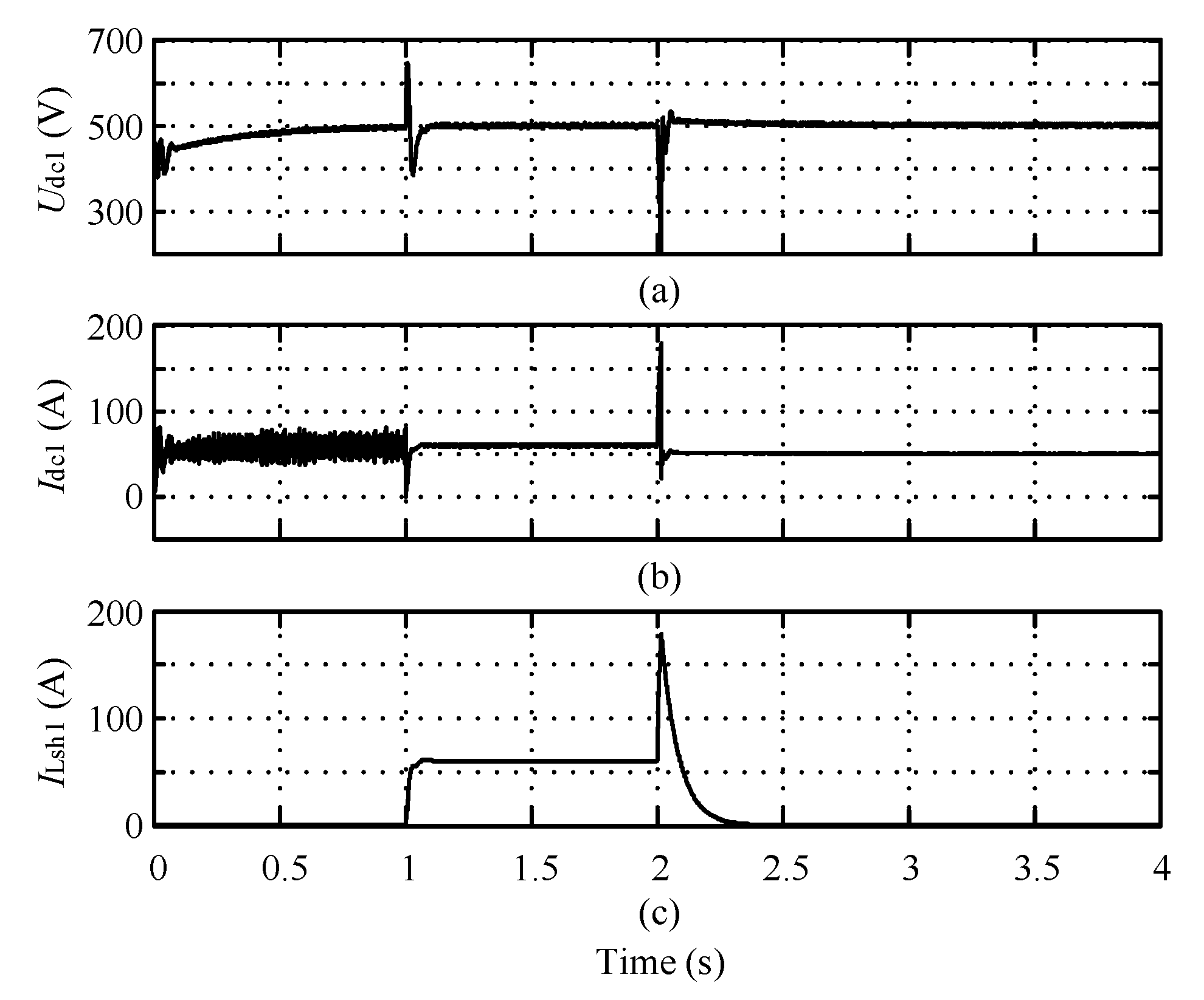
5.2. Bipolar Short Circuit Fault of Large Current Type

In the simulation of large-current fault, the bipolar fault resistance is 0.01 Ω, smaller than the load resistance (8.3 Ω). Because of the similarity between the VSC DC side wave and the boost converter DC side wave, the simulation of bipolar short-circuit simulation of large current is given in this paper with the time interval of 0 s–4 s, as shown in Figure 9. In Figure 9a, the voltage Udc1 across the capacitance C1 is drawn; in Figure 9b, the circuit current Idc1 on the VSC side is given. In Figure 9c, the waveform of the current ILsh1 on the current-limiting inductance in the FCL1 is given. Figure 10 is the VSC side simulation curve before and after the failure.
As shown in Figure 9, the system started at the interval of 0–1 s. In Figure 9a, the voltage Udc1 across the capacitance CC1 gradually rose to the rated voltage of 500 V; in Figure 9b, the current waveform of Idc1 demonstrated a fluctuation on the VSC side during the start-up process. In Figure 9c, because K1 in the FCL1 was switched off and the current-limiter was short-circuited, ILsh1 was zero.
At 1s, K1 was disconnected while K2 was closed, and the current-limiter began to work. During 1 s to 2 s, the system operated normally. Due to the current-limiting inductance, the DC bus voltage and DC line current entered steady state after a short fluctuation. Udc1 in Figure 9a reached 500 V while Idc1 in Figure 9b reached 60 A; ILsh1 in Figure 9c gradually increased from 0 to the rated current of 60 A. A short circuit fault occurred in the distribution line at 2 s. The fault process of 2 s–2.05 s is shown in Figure 10. As analyzed in Section 3.2, the current-limiting inductance extends the discharge time of the capacitor and the rise speed of the impact current. In Figure 10a, Udc1 of the capacitor C1 did not decrease to 0 V rapidly. At 2.017 s, the line current Idc1 rose to about 170 A and reached the threshold of amplitude-limiting, that is, Idc ≥ 2IN. At this moment, K2 was disconnected and K3 was closed. The amplitude-limiting circuit was connected to prevent the capacitance from discharging rapidly. In this case, Udc1 in Figure 10a only decreased to 200 V and restored to normal operation at 500 V in 5ms. The DC side line current Idc1 in Figure 10b restored to normal operation at 50 A in 4 ms. The K4 was closed while K3 was closed, and the energy leakage circuit was connected, which caused the current flowing through the current-limiting inductance ILsh1 to decrease from 170 A to 0 A in 0.34 s in Figure 10c and thus the current-limiting capacity was restored.

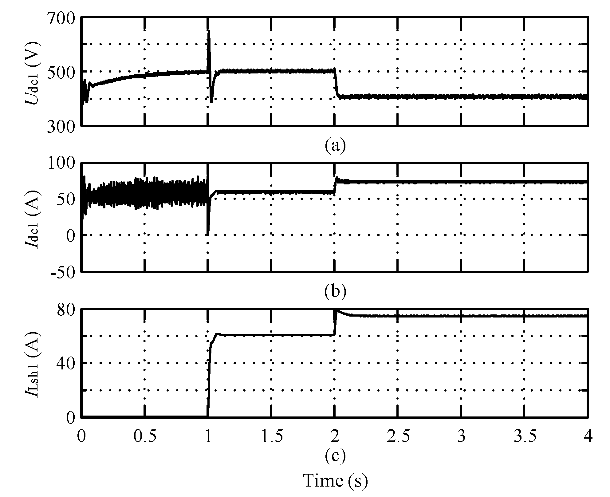
5.3. Bipolar Short Circuit Fault of Small Current Type

In the small current fault simulation, the resistance for a bipolar short circuit fault is 16 Ω, 2 times larger than the load resistance (8.3 Ω). The DC simulation curves on the VSC side and boost converter side are demonstrated in Figure 11 and Figure 12, respectively.
1.
Simulation curve on VSC side
As shown in Figure 11, the system started at 0s–1s and operated normally during 1 s–2 s. At this time, K1, K3 and K4 were disconnected while K2 was closed, and the current-limiting circuit of FCL1 was connected. At 2 s, a small current short circuit fault occurred in the distribution line. Due to the variation range of the line current which did not meet the large current condition, K2 was still closed and the FCL1 worked in the current-limiting state. In Figure 8, the capacitance C1 discharged through the short-circuit resistance, resulting in a decrease of Udc1to 400V in Figure 11a. The short-circuit resistance caused the load equivalent resistance to decrease, resulting in an increase of DC side line current Idc1 to 73 A in Figure 11b; moreover, the close of K2 made the line current the same as the one in the current-limiting inductance in FCL1, so the current ILsh1in Figure 11c which flowed through the current-limiting inductance was 73 A, too. At this point, for the circuit breaker trip, conditions were not reached and the fault current remained stable.
2.
Simulation Curve on Boost Converter Side
As shown in Figure 12, the system started at 0s–1s and operated normally during 1 s–2 s. At this time, K1, K3 and K4 were disconnected while K2 was closed, and the current-limiting circuit of FCL2 was connected. At 2 s, a small current short circuit fault occurred in the distribution line. Due to the variation range of the line current which did not meet the large current condition, K2 was still closed and the FCL2 worked in the current-limiting state. In Figure 8, the capacitance Cb discharged through the short-circuit resistance, resulting in a decrease of Udc2 in Figure 12a to 400 V. The short-circuit resistance shunt caused a decrease of booster converter side line current Idc2 from −60 A to −50A in Figure 12b (follow the specified direction in Figure 9).
In Figure 12c, the load current dropped from the rated value of 60 A to 48 A. Moreover, the close of K2 made the line current the same as the one in the current-limiting inductance in FCL2, so the current ILsh2 in Figure 12d which flowed through the current-limiting inductance became 50 A. At this point, because the circuit breaker trip conditions were not reached, the fault current remained stable, which conformed to the condition that Iload < 10%IN.
To sum up, the FCL and fault ride-through strategy proposed in this paper can realize both the fault ride-through of large currents and fault ride-through of small currents.

6. Conclusions

To deal with the fault ride-through problem of LVDC distribution network, based on the collected electrical quantities and control methods, we designed an FCL which is connected in series at the ends of the distribution lines. The conclusions are drawn as follows:
1.
The feasibility of the FCL connecting to the network was discussed in detail and the structure of the d FCL was given in detail; the principle of parameter design was discussed and presented.
2.
To verify our proposed FCL, under the most serious conditions, a model was built and simulated. From the simulated results, we can see that FCL can reduce the fault current impact and limit fault current amplitude, which earns some time for fault detection, control, protection and ride-through action. After fault disappears, it will switch back to the current-limiting state and restore the normal operation. If the fault still exists, through cooperation with DCCB, the differential protection should be used as the backup protection of FCL. The identification of short-circuit fault of small current can be realized by monitoring the DC power at the load end.
In the future, we will focus on the design of the DC FCL of multiterminal LVDC system connected by distributed power supply and on developing an intelligent FCL with multiple functions such as detection, operation and protection for practical application.

Author Contributions

Conceptualization, B.H. and Y.L.; methodology, B.H.; software, B.H.; validation, B.H. and Y.L.; formal analysis, B.H.; investigation, B.H.; resources, B.H.; data curation, B.H.; writing—original draft preparation, B.H.; writing—review and editing, B.H.; visualization, B.H.; supervision, Y.L.; project administration, Y.L.; funding acquisition, Y.L. All authors have read and agreed to the published version of the manuscript.

Funding

This research received no external funding.

Conflicts of Interest

The authors declare no conflict of interest.

References

  1. Dragičević, T.; Lu, X.; Vasquez, J.C.; Guerrero, J.M. DC Microgrids—Part II: A Review of Power Architectures, Applications, and Standardization Issues. IEEE Trans. Power Electron. 2016, 31, 3528–3549. [Google Scholar]
  2. Justo, J.J.; Mwasilu, F.; Lee, J.; Jung, J.W. AC-microgrids versus DC microgrids with distributed energy resources: A review. Renew. Sustain. Energy Rev. 2013, 24, 387–405. [Google Scholar] [CrossRef]
  3. Chakraborty, C.; Iu, H.H.; Dah-Chuan Lu, D. Power converters, control, and energy management for distributed generation. IEEE Trans. Ind. Electron. 2015, 62, 4466–4470. [Google Scholar] [CrossRef]
  4. Dragičević, T.; Lu, X.; Vasquez, J.C.; Guerrero, J.M. DC Microgrids—Part I: A Review of Control Strategies and Stabilization Techniques. IEEE Trans. Power Electron. 2016, 31, 4876–4891. [Google Scholar]
  5. IEEE. IEEE Draft Standard for Interconnection and Interoperability of Distributed Energy Resources with Associated Electric Power Systems Interfaces; IEEE P1547/D7.3, December 2017; IEEE: Piscataway, NJ, USA, 2017; pp. 1–148. [Google Scholar]
  6. IEEE. IEEE Standard for Interconnection and Interoperability of Distributed Energy Resources with Associated Electric Power Systems Interfaces; IEEE Std 1547-2018.; IEEE: Piscataway, NJ, USA, 2018; pp. 1–138. [Google Scholar]
  7. Emhemed, A.A.S.; Burt, G.M. An Advanced Protection Scheme for Enabling an LVDC Last Mile Distribution Network. IEEE Trans. Smart Grid. 2014, 5, 2602–2609. [Google Scholar] [CrossRef] [Green Version]
  8. Chen, L.; Zhang, X.; Qin, Y.; Chen, H.; Shen, Q.; Xu, Y.; Ren, L.; Tang, Y. Application and Design of a Resistive-Type Superconducting Fault Current Limiter for Efficient Protection of a DC Microgrid. IEEE Trans. Appl. Superconduct. 2019, 29, 1–7. [Google Scholar] [CrossRef]
  9. Li, B.; He, J.; Li, Y.; Li, R. A Novel Solid-State Circuit Breaker with Self-Adapt Fault Current Limiting Capability for LVDC Distribution Network. IEEE Trans. Power Electron. 2019, 34, 3516–3529. [Google Scholar] [CrossRef]
  10. Rashid, G.; Ali, M.H. A Modified Bridge-Type Fault Current Limiter for Fault Ride-Through Capacity Enhancement of Fixed Speed Wind Generator. IEEE Trans. Energy Convers. 2014, 29, 527–534. [Google Scholar]
  11. Mahamedi, B.; Eskandari, M.; Fletcher, J.E.; Zhu, J. Sequence-Based Control Strategy with Current Limiting for the Fault Ride-Through of Inverter-Interfaced Distributed Generators. IEEE Trans. Sustain. Energy 2020, 11, 165–174. [Google Scholar] [CrossRef]
  12. Shabestary, M.M.; Mohamed, Y.A.I. Autonomous Coordinated Control Scheme for Cooperative Asymmetric Low-Voltage Ride-Through and Grid Support in Active Distribution Networks with Multiple DG Units. IEEE Trans. Smart Grid 2019. [Google Scholar] [CrossRef]
  13. Lin, L.; He, Z.; Hu, J.; He, Z.; Xu, K. Pole-to-ground fault ride through strategy for half-/full-bridge hybrid MMC-based radial multi-terminal HVDC systems with low-impedance grounded. IET Gener. Transm. Distrib. 2018, 12, 1038–1044. [Google Scholar] [CrossRef]
  14. Attya, A.B.; Comech, M.P.; Omar, I. Comprehensive study on fault-ride through and voltage support by wind power generation in AC and DC transmission systems. J. Eng. 2019, 2019, 5152–5157. [Google Scholar] [CrossRef]
  15. Vu, T.; Paran, S.; Diaz-Franco, F.; El-Mezyani, T.; Edrington, C.S. An Alternative Distributed Control Architecture for Improvement in the Transient Response of DC Microgrids. IEEE Trans. Ind. Electron. 2016, 64, 574–584. [Google Scholar] [CrossRef] [Green Version]
  16. Emhemed, A.; Fong, K.; Fletcher, S.; Burt, G.M. Validation of fast and selective protection scheme for an LVDC distribution network. IEEE Trans. Power Deliv. 2017, 32, 1432–1440. [Google Scholar] [CrossRef] [Green Version]
  17. Shuai, Z.; He, N.; Xiong, Z.; Lei, Z.; Shen, Z.J. Comparative Study of Short-Circuit Fault Characteristics for VSC-Based DC Distribution Networks with Different Distributed Generators. IEEE J. Emerg. Sel. Top. Power Electron. 2018, 7, 528–540. [Google Scholar] [CrossRef]
  18. Monjo, L.; Mesas, J.J.; Sainz, L.; Pedra, J.; Monjo, L. Study of cable short circuit in VSC DC systems. In Proceedings of the 2015 International Symposium on Smart Electric Distribution Systems and Technologies (EDST), Vienna, Austria, 8–11 September 2015; Volume 33, pp. 230–234. [Google Scholar]
  19. Emhemed, A.; Burt, G.M. The effectiveness of using IEC61660 for characterising short-circuit currents of future low voltage DC distribution networks. In Proceedings of the 22nd International Conference and Exhibition on Electricity Distribution (CIRED 2013), Stockholm, Sweden, 10–13 June 2013; Volume 11, pp. 1–4. [Google Scholar]
  20. Yang, J.; Fletcher, J.E.; O’Reilly, J. Short-Circuit and Ground Fault Analyses and Location in VSC-Based DC Network Cables. IEEE Trans. Ind. Electron. 2011, 59, 3827–3837. [Google Scholar] [CrossRef] [Green Version]
  21. Nourmohamadi, H.; Nazari-Heris, M.; Sabahi, M.; Abapour, M. A Novel Structure for Bridge-Type Fault Current Limiter: Capacitor-Based Nonsuperconducting FCL. IEEE Trans. Power Electron. 2017, 33, 3044–3051. [Google Scholar] [CrossRef]
  22. Radmanesh, H.; Fathi, S.; Gharehpetian, G.B.; Heidary, A. Bridge-Type Solid-State Fault Current Limiter Based on AC/DC Reactor. IEEE Trans. Power Deliv. 2016, 31, 200–209. [Google Scholar] [CrossRef]
  23. Chen, S.; Li, P.; Ball, R.; De Palma, J.-F.; Lehman, B. Analysis of a Switched Impedance Transformer-Type Nonsuperconducting Fault Current Limiter. IEEE Trans. Power Electron. 2014, 30, 1925–1936. [Google Scholar] [CrossRef]
Figure 1. Structure of a LVDC distribution network.
Energies 13 01753 g001
Figure 2. Structure of a LVDC distribution network.
Energies 13 01753 g002
Figure 3. Equivalent circuits for the short-circuit fault at capacitor discharge stage.
Energies 13 01753 g003
Figure 4. Equivalent circuits for the short-circuit fault at diode freewheel stage.
Energies 13 01753 g004
Figure 5. Equivalent circuits for the short-circuit fault at steady-state stage.
Energies 13 01753 g005
Figure 6. Structure of DC FCL.
Energies 13 01753 g006
Figure 7. Fault ride-through strategy based on DC FCL.
Energies 13 01753 g007
Figure 8. Equivalent circuit of LVDC distribution network connected by DC FCL.
Energies 13 01753 g008
Figure 9. Simulation curve of voltage source converter (VSC) side of large current bipolar short circuit. (a) Capacitor C1 voltage Udc1. (b) VSC-side cable current Idc1. (c) Current over current-limiting inductor in FCL1 ILsh1.
Energies 13 01753 g009
Figure 10. Simulation curve of VSC side of large current bipolar short circuit (local enlargement). (a) Capacitor C1voltageUdc1. (b) VSC-side cable currentIdc1. (c) current over current limiting inductor in FCL1ILsh1.
Energies 13 01753 g010
Figure 11. Simulation curve of VSC side of small current bipolar short circuit. (a) Capacitor C1 voltage Udc1. (b) VSC-side cable current Idc1. (c) current over current-limiting inductor in FCL1 ILsh1.
Energies 13 01753 g011
Figure 12. Simulation curve of boost converter side of small current bipolar short circuit. (a) Capacitor Cb voltage Udc2. (b) VSC-side cable current Idc2. (c) Load resistance current Iload. (d) Current over current-limiting inductor in FCL2 ILsh2.
Energies 13 01753 g012
Table 1. Logic function of DC FCL.
FunctionK1K2K3K4
Start1000
Normal0100
Fault momentary0100
Initial failure0100
Failure period0011
Fault disappear0100
In the table, “1” represents close while “0” represents disconnect.
Table 2. Simulation parameters.
ParameterValue
Rated DC voltage (V)500
Rated DC current (A)60
DC side busbar capacitance (F)0.002
Load resistance (Ω)8.3
DC line resistor (Ω⁄km)1
DC line inductor (H⁄km)0.01
Large current fault resistance (Ω)0.01
Small current fault resistance (Ω)83

